Vehicle Battery Cooling Device And Battery Module
NODA; Yoshitoshi
U.S. patent application number 16/717684 was filed with the patent office on 2020-04-23 for vehicle battery cooling device and battery module. This patent application is currently assigned to PANASONIC INTELLECTUAL PROPERTY MANAGEMENT CO., LTD.. The applicant listed for this patent is PANASONIC INTELLECTUAL PROPERTY MANAGEMENT CO., LTD.. Invention is credited to Yoshitoshi NODA.
| Application Number | 20200127346 16/717684 |
| Document ID | / |
| Family ID | 64737018 |
| Filed Date | 2020-04-23 |


| United States Patent Application | 20200127346 |
| Kind Code | A1 |
| NODA; Yoshitoshi | April 23, 2020 |
VEHICLE BATTERY COOLING DEVICE AND BATTERY MODULE
Abstract
A vehicle battery cooling device adapted to cool a battery pack including a plurality of unit batteries includes: a case that contains a cooling fluid for cooling the battery pack; a pipe which runs inside the case and in which a cooling medium for cooling the cooling fluid is caused to flow; and a control valve that is provided in the pipe and discharges the cooling medium in the case in accordance with a temperature of the battery pack.
| Inventors: | NODA; Yoshitoshi; (Kanagawa, JP) | ||||||||||
| Applicant: |
|
||||||||||
|---|---|---|---|---|---|---|---|---|---|---|---|
| Assignee: | PANASONIC INTELLECTUAL PROPERTY
MANAGEMENT CO., LTD. Osaka JP |
||||||||||
| Family ID: | 64737018 | ||||||||||
| Appl. No.: | 16/717684 | ||||||||||
| Filed: | December 17, 2019 |
Related U.S. Patent Documents
| Application Number | Filing Date | Patent Number | ||
|---|---|---|---|---|
| PCT/JP2018/023068 | Jun 18, 2018 | |||
| 16717684 | ||||
| Current U.S. Class: | 1/1 |
| Current CPC Class: | H01M 2/1077 20130101; H01M 10/486 20130101; H01M 10/6552 20150401; H01M 10/6556 20150401; H01M 10/625 20150401; H01M 10/63 20150401; H01M 2220/20 20130101; H01M 10/613 20150401; B60K 11/04 20130101; H01M 10/656 20150401; H01M 10/6568 20150401; B60K 1/04 20130101; B60L 50/64 20190201; B60L 58/26 20190201; H01M 2/1083 20130101 |
| International Class: | H01M 10/625 20060101 H01M010/625; H01M 10/656 20060101 H01M010/656; H01M 2/10 20060101 H01M002/10 |
Foreign Application Data
| Date | Code | Application Number |
|---|---|---|
| Jun 20, 2017 | JP | 2017-120589 |
Claims
1. A vehicle battery cooling device adapted to cool a battery pack including a plurality of unit batteries, comprising: a case that contains a cooling fluid for cooling the battery pack; a pipe which runs inside the case and in which a cooling medium for cooling the cooling fluid is caused to flow; and a control valve that is provided in the pipe and discharges the cooling medium in the case in accordance with a temperature of the battery pack.
2. The vehicle battery cooling device according to claim 1, further comprising: a stirrer that stirs the cooling fluid.
3. The vehicle battery cooling device according to claim 1, further comprising: a cooling control unit that controls the control valve, wherein the cooling control unit opens the control valve when the battery pack, which is deactivated upon detection of an abnormality of the unit battery, reaches a predetermined temperature.
4. The vehicle battery cooling device according to claim 2, further comprising: a cooling control unit that controls the control valve, wherein the cooling control unit opens the control valve when the battery pack, which is deactivated upon detection of an abnormality of the unit battery, reaches a predetermined temperature.
5. A battery module comprising: the vehicle battery cooling device according to claim 1; and a battery pack mounted in the vehicle battery cooling device and including a plurality of unit batteries.
6. A battery module comprising: the vehicle battery cooling device according to claim 2; and a battery pack mounted in the vehicle battery cooling device and including a plurality of unit batteries.
7. A battery module comprising: the vehicle battery cooling device according to claim 3; and a battery pack mounted in the vehicle battery cooling device and including a plurality of unit batteries.
8. A battery module comprising: the vehicle battery cooling device according to claim 4; and a battery pack mounted in the vehicle battery cooling device and including a plurality of unit batteries.
Description
BACKGROUND
1. Field
[0001] The present disclosure relates to vehicle battery cooling devices and battery modules.
2. Description of the Related Art
[0002] A battery module for supplying power to a motor as a driving source is mounted on a hybrid vehicle or an electric vehicle. The battery module includes a battery pack comprised of a plurality of unit batteries. Thermal runaway (abnormal temperature increase) may occur in the unit battery provided in the battery pack due, for example, to a short circuit.
[0003] A battery device (battery module) designed to inject an incombustible cooling medium from a predetermined valve to a location exposed to the combustion gas generated from the unit battery accommodated in the case is known as a technology to cool the unit battery in which thermal runaway occurs (see, for example, patent literature 1). [0004] [Patent literature 1] JP2009-238654
[0005] In the battery device according to patent literature 1, the device may not be sufficiently cooled even when the cooling medium is injected into the interior of the case, if the unit battery in which thermal runaway occurs is remote from the valve that injects the cooling medium. It is conceivable to detect the position of the unit battery in which thermal runaway occurs and change the position or direction in which the cooling medium is injected. In this case, however, the setup may become complicated.
SUMMARY
[0006] The disclosure addresses the above-described issue, and a general purpose thereof is to provide a vehicle battery cooling device capable of cooling the entirety of the battery pack uniformly by means of a simple setup, when thermal runaway occurs in the unit battery in the battery pack.
[0007] An embodiment of the present disclosure relates to a vehicle battery cooling device adapted to cool a battery pack including a plurality of unit batteries. The vehicle battery cooling device includes: a case that contains a cooling fluid for cooling the battery pack; a pipe which runs inside the case and in which a cooling medium for cooling the cooling fluid is caused to flow; and a control valve that is provided in the pipe and discharges the cooling medium in the case in accordance with a temperature of the battery pack.
BRIEF DESCRIPTION OF THE DRAWINGS
[0008] Embodiments will now be described by way of examples only, with reference to the accompanying drawings which are meant to be exemplary, not limiting and wherein like elements are numbered alike in several Figures in which:
[0009] FIG. 1 shows a battery module according to the embodiment;
[0010] FIG. 2 is a perspective view of the cooling device according to the embodiment;
[0011] FIG. 3 is an exploded view of the cooling device according to the embodiment;
[0012] FIG. 4 is a perspective view showing a route of the pipe according to the embodiment;
[0013] FIG. 5 is a block diagram showing a configuration of the battery module according to the embodiment; and
[0014] FIG. 6 is a flowchart of a cooling process performed by the battery module according to the embodiment.
DETAILED DESCRIPTION
[0015] The invention will now be described by reference to the preferred embodiments. This does not intend to limit the scope of the present invention, but to exemplify the invention.
[0016] In the embodiment described in the following, the same constituting elements shall be denoted by the same reference numerals, and duplicative explanations will be omitted. For convenience of the description, some of the constituting elements are omitted as needed in the drawings.
[0017] A summary will be given before describing the embodiment of the present disclosure in specific details. The embodiment relates to a vehicle battery cooling device for cooling a battery pack mounted on a vehicle. The vehicle battery cooling device includes a case in which the battery pack is mounted and a pipe that runs inside the case. A cooling fluid for cooling the battery pack is contained in the case. A cooling medium for cooling the cooling fluid is caused to flow in the pipe. A control valve is provided in the pipe in the case. In the case thermal runaway occurs in any of a plurality of unit batteries forming the battery pack, the control valve is opened to discharge the cooling medium in the case (in the cooling fluid). The cooling medium will be at an extremely low temperature (-20.degree. or below) when relieved from a low-pressure condition and discharged to the atmosphere. As the cooling medium spreads in the cooling fluid, the temperature of the entirety of the case is lowered. This makes it possible to cool the entirety of the battery pack uniformly. The unit battery in which thermal runaway occurs can be cooled regardless of its position. The embodiment will now be given in specific details.
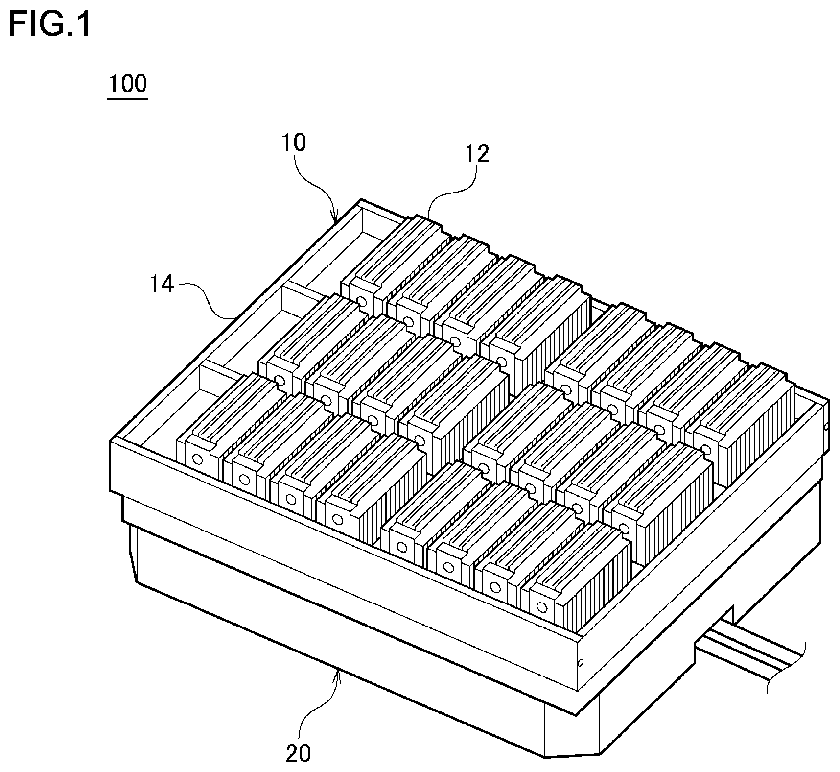
[0018] FIG. 1 is a perspective view of a battery module 100 according to the embodiment of the present disclosure. The battery module 100 includes a battery pack 10 and a vehicle battery cooling device 20. Hereinafter, the vehicle battery cooling device 20 will simply be referred to as the cooling device 20. The battery pack 10 includes a plurality of unit batteries 12 connected to each other and supplies power to a driving motor of a vehicle (not shown). The unit battery 12 is a lithium ion secondary battery and is housed in a housing 14 made of an aluminum alloy. The battery pack 10 is mounted on the top surface of the cooling device 20, and each unit battery 12 is cooled from the bottom side.
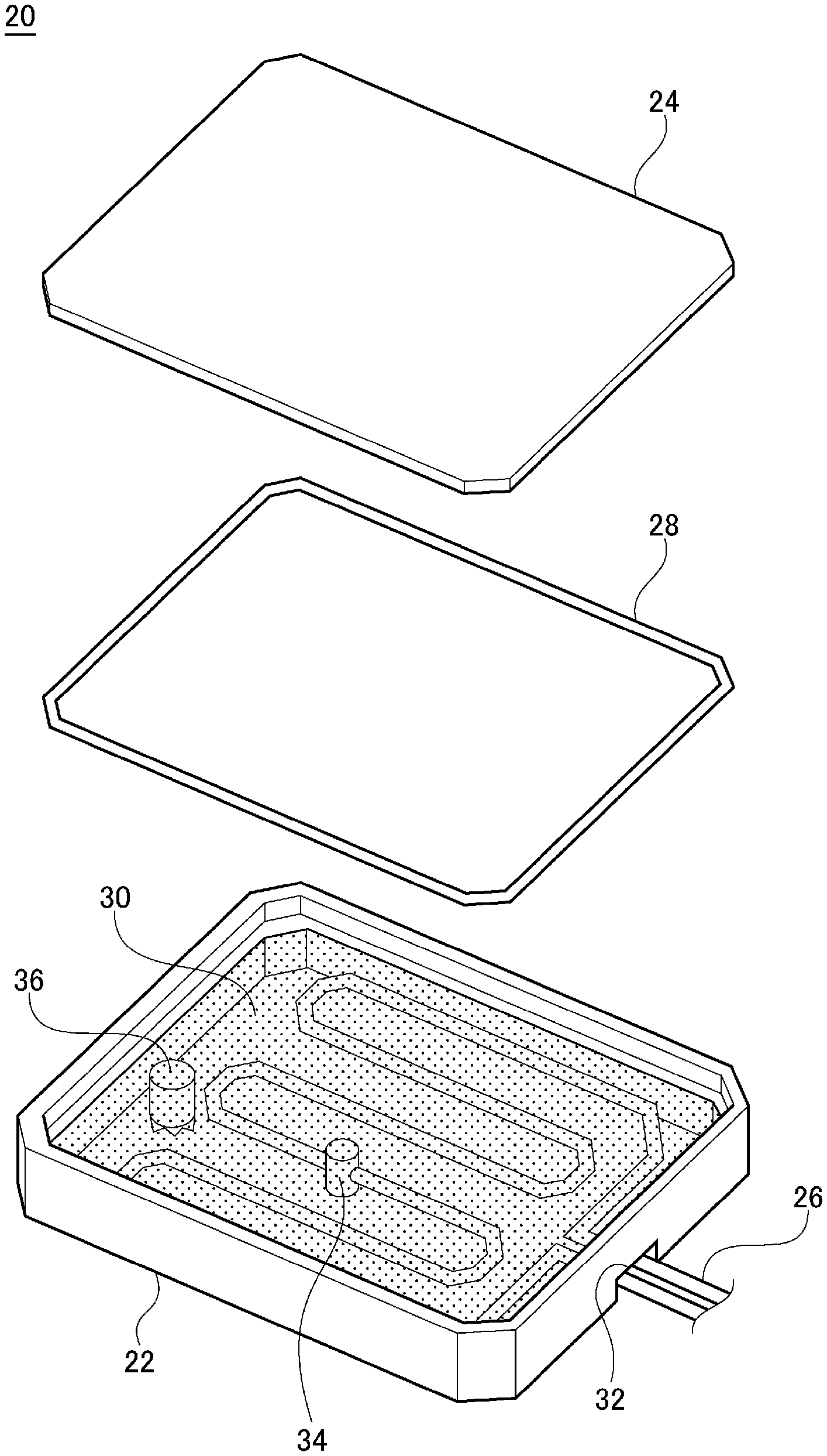
[0019] FIG. 2 is a perspective view of the cooling device 20 according to the embodiment of the present disclosure, and FIG. 3 is an exploded view thereof. The cooling device 20 includes a case 22, a cover 24, a pipe 26, an O-ring 28, a control valve 34, and a stirrer 36. The case 22 is made of a resin material to have a shape of box with an open top. A cooling fluid 30 is contained in the case 22. The cooling fluid 30 is an antifreezing fluid that contains ethylene glycol. The cover 24 is made of a resin material to have the same shape as the opening of the case 22. The cover 24 covers the opening of the case 22 and is fixed accordingly. The O-ring 28 is sandwiched between the case 22 and the cover 24 and seals a space that contains the cooling fluid 30.
[0020] The pipe 26 runs inside the case 22. The cooling medium for cooling the cooling fluid 30 is caused to flow in the pipe 26. One example of the cooling medium is hydro fluoro carbon (HFC). The pipe 26 is guided into the interior of the case 22 through a pipe port 32 in the lateral surface. The pipe 26 runs back and forth inside the case 22 and is guided outside through the pipe port 32. The pipe port 32 is sealed by a sealing member (not shown). The control valve 34 is provided in the pipe 26 that runs inside the case 22.
[0021] The control valve 34 is a motor-operated two-way valve configured such that the valve is opened and closed by moving a plunger by means of a solenoid. The control valve 34 opens in accordance with the temperature of the battery pack 10 to discharge the cooling medium into the case 22. The cooling medium will be at an extremely low temperature (-20.degree. or below) by being relieved from a low-pressure condition in the pipe 26 and discharged to the atmosphere. As the discharged cooling medium spreads in the cooling fluid 30, the temperature of the entirety of the case 22 is lowered so that the battery pack 10 is cooled uniformly. The embodiment is non-limiting as to the position of the control valve 34 so long as the control valve 34 is located inside the case 22. The case 22 is also provided with a pressure control valve (not shown). The pressure control valve is opened when the control valve 34 discharges the cooling medium to maintain the pressure inside constant by discharging the gas within the case outside.
[0022] The stirrer 36 is a stirring fan provided with a rotary impeller. The stirrer 36 is provided inside the case 22 to stir the cooling fluid 30. The stirring by the stirrer 36 reduces the temperature difference in the cooling fluid 30 inside the case 22. The stirring also accelerates the spread of the cooling medium in the case 22 as the cooling medium is discharged from the control valve 34. This lowers the temperature of the entirety of the case 22 in a short period of time. An electric water pump may be used as the stirrer 36. In this case, the same advantage is provided. The operation of the control valve 34 and the stirrer 36 is controlled by a cooling control unit described later connected via a wiring that runs through the pipe port 32.
[0023] FIG. 4 is a perspective view showing a route of the pipe 26 according to the embodiment of the disclosure. A compressor 38, a condenser 40, and an expansion valve 42 are provided in the route of the pipe 26. The compressor 38 compresses the cooling medium (gas cooling medium) that has passed through the cooling device 20 and absorbed the heat of the battery pack 10. The cooling medium compressed and turned into a high-pressure gas is cooled in the condenser 40 by an air blower (not shown) and is liquified accordingly. The liquified cooling medium is injected into the pipe 26 inside the cooling device 20 from a minute hole of the expansion valve 42. The cooling medium is placed in a gas-liquid mixture state at a low temperature and a low pressure. The cooling medium absorbs the heat around, including the heat of the battery pack 10, via the cooling fluid 30 as it passes through the interior of the cooling device 20. The cooling medium that has cooled the battery pack 10 via the cooling fluid flows from the cooling device 20 to return to the compressor 38.
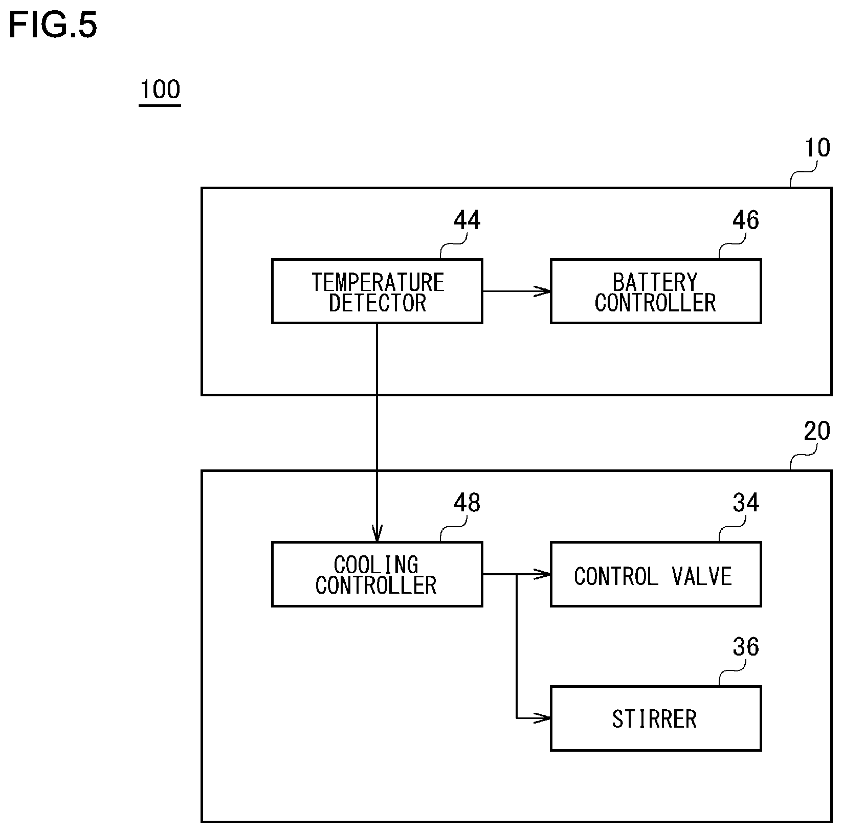
[0024] FIG. 5 is a block diagram showing a configuration of the battery module 100 according to the embodiment of the present disclosure. The blocks depicted in the block diagram of this specification are implemented in hardware such as devices like a CPU of a computer or mechanical components, and in software such as a computer program etc. FIG. 5 depicts functional blocks implemented by the cooperation of these elements. Therefore, it will be understood by those skilled in the art that the functional blocks may be implemented in a variety of manners by a combination of hardware and software.
[0025] The battery pack 10 includes a temperature detection unit 44 and a battery control unit 46. The temperature detection unit 44 detects the temperature of the battery pack 10 according to a publicly-known related-art technology. The battery control unit 46 controls the supply of power from the battery pack 10 to the respective parts including the driving motor. When the temperature of the battery pack 10 exceeds a first temperature, the battery control unit 46 cuts off the supply of power to the respective parts and deactivates the battery pack 10. The first temperature is a threshold value at which it is determined that an abnormality occurs in the unit battery 12 inside the battery pack 10 and is predefined.
[0026] The cooling device 20 includes a cooling control unit 48 for controlling the control valve 34 and the stirrer 36. When the temperature of the battery pack 10 after an elapse of a predetermined period of time since the deactivation by the battery control unit 46 exceeds a second temperature, the cooling control unit 48 opens the control valve 34 and drives the stirrer 36. The second temperature is a temperature at which it is determined that thermal runaway occurs in one or more unit batteries 12 in the battery pack 10. The second temperature is predefined to be equal to or higher than the first temperature.
[0027] FIG. 6 is a flowchart of a cooling process performed by the battery module 100 according to the embodiment of the present disclosure. The battery module 100 performs the cooling process shown in FIG. 6 repeatedly at a predetermined period.
[0028] First, the temperature detection unit 44 detects the temperature of the battery pack 10 (S11). The battery control unit 46 then compares the temperature of the battery pack 10 with the aforementioned first temperature (S12). When the temperature of the battery pack 10 is equal or higher than the first temperature (Y in S12), there is a possibility that an abnormality occurs in the unit battery 12 inside the battery pack 10. Therefore, the battery control unit 46 cuts off the supply of power to the respective parts and deactivates the battery pack 10 (S13). When the temperature of the battery pack 10 is below the first temperature (N in S12), it is determined that the unit batteries 12 inside the battery pack 10 are operating normally, and the process is terminated.
[0029] In the case the battery pack 10 is deactivated, the temperature detection unit 44 detects the temperature of the battery pack 10 again upon an elapse of a predetermined period of time since the deactivation (S14). The cooling control unit 48 compares the temperature of the battery pack 10 with the aforementioned second temperature (S15). When the temperature of the battery pack 10 is not lowered and is increased to the second temperature or higher despite an elapse of a predetermined period of time since the deactivation (Y in S15), there is a possibility that thermal runaway due to, for example, a short circuit occurs in one or more unit batteries 12 so that the cooling control unit 48 opens the control valve 34 (S16). The cooling control unit 48 also drives the stirrer 36 (S17). When the control valve 34 is opened, the cooling medium is injected into the interior of the case 22, which is placed at a lower pressure than the interior of the pipe 26, spreading the cooling medium inside the case 22. Further, the stirrer 36 is driven so that the cooling medium spreads in the entirety of the case 22 in one sitting. This lowers the temperature of the entirety of the case 22 and cools the battery pack 10 uniformly.
[0030] When the temperature becomes lower than the second temperature after an elapse of a predetermined period of time since the deactivation of the battery pack 10 (N in S15), it is determined that thermal runaway of the unit battery 12 is not occurring. Accordingly, the cooling medium is not discharged, and the process is terminated. The cooling device 20 in which the cooling medium is discharged once cannot continue to be used and so need be replaced. Unnecessary replacement of the cooling device 20 is avoided by performing a process whereby the cooling medium is not discharged when the temperature is lowered after the battery pack 10 is deactivated. When the temperature of the battery pack 10 becomes the first temperature or higher, the operator may be alerted of an abnormality of the battery via a display or a speaker provided in the vehicle interior. This can prompt the operator to react to the situation promptly.
[0031] According to the embodiment of the present disclosure, the battery pack 10 is cooled uniformly with a simple setup when thermal runaway occurs in the unit battery in the battery pack 10. The entirety of the battery pack 10 is cooled so that the unit battery 12 in which thermal runaway occurs is cooled properly regardless of its position.
[0032] Described above is an explanation based on an exemplary embodiment. The embodiment is intended to be illustrative only and it will be understood by those skilled in the art that various modifications to constituting elements and processes could be developed and that such modifications are also within the scope of the present disclosure.
[0033] For example, a plurality of control valves 34, a plurality of stirrers 36, or a plurality of control valves 34 and stirrers 36 may be provided in the cooling device 20. In this case, the temperature of the entirety of the case 22 is lowered in a short period of time when the control valve 34 is opened. The temperature detection unit 44 may detect the temperature of the plurality of unit batteries 12 individually. In this case, an abnormality of the unit battery 12 is detected more precisely. In the embodiment, the stirrer 36 is driven when the control valve 34 is opened, but stirrer 36 may be driven at all times. In this case, the entirety of the case 22 is maintained at a uniform temperature so that the cooling performance of the battery pack 10 is improved.
[0034] One embodiment of the present disclosure is summarized below. An embodiment of the present disclosure relates to a vehicle battery cooling device 20 adapted to cool a battery pack 10 including a plurality of unit batteries 12. The vehicle battery cooling device 20 includes: a case 22 that contains a cooling fluid 30 for cooling the battery pack 10; a pipe 26 which runs inside the case 22 and in which a cooling medium for cooling the cooling fluid 30 is caused to flow; and a control valve 34 that is provided in the pipe 26 and discharges the cooling medium in the case 22 in accordance with a temperature of the battery pack 10.
[0035] According to this embodiment, the cooling medium having a lower temperature than the cooling fluid 30 spreads when the control valve 34 is opened in accordance with the temperature of the battery pack 10, lowering the temperature of the entirety of the case 22. This uniformly cools the entirety of the battery pack 10 in which an abnormality such as thermal runaway of the unit battery 12 occurs.
[0036] The device may include a stirrer 36 that stirs the cooling fluid 30. In this case, the cooling medium discharged from the control valve 34 spreads in the cooling fluid 30 in a short period of time so that the battery pack 10 is cooled in a shorter period of time.
[0037] The device may include a cooling control unit 48 that controls the control valve 34. The cooling control unit 48 may open the control valve 34 when the battery pack 10, which is deactivated upon detection of an abnormality of the unit battery, reaches a predetermined temperature. In this case, the control valve 34 is inhibited from being opened undesirably to discharge the cooling medium.
[0038] Another embodiment of the present disclosure relates to a battery module 100 including: the vehicle battery cooling device 20; and a battery pack 10 mounted in the vehicle battery cooling device 20 and including a plurality of unit batteries 12. According to this embodiment, the entirety of the battery pack 10 is cooled uniformly when an abnormality such as thermal runaway of the unit battery 12 occurs so that troubles such as injection of the combustion gas or fire from the unit battery 12 are inhibited.
[0039] While various embodiments have been described herein above, it is to be appreciated that various changes in form and detail may be made without departing from the spirit and scope of the invention(s) presently or hereafter claimed.
CROSS-REFERENCE TO RELATED APPLICATION
[0040] This application is based upon and claims the benefit of priority from the prior Japanese Patent Application No. 2017-120589, filed on Jun. 20, 2017, the entire contents of which are incorporated herein by reference.
* * * * *
D00000
D00001
D00002
D00003
D00004
D00005
D00006
XML
uspto.report is an independent third-party trademark research tool that is not affiliated, endorsed, or sponsored by the United States Patent and Trademark Office (USPTO) or any other governmental organization. The information provided by uspto.report is based on publicly available data at the time of writing and is intended for informational purposes only.
While we strive to provide accurate and up-to-date information, we do not guarantee the accuracy, completeness, reliability, or suitability of the information displayed on this site. The use of this site is at your own risk. Any reliance you place on such information is therefore strictly at your own risk.
All official trademark data, including owner information, should be verified by visiting the official USPTO website at www.uspto.gov. This site is not intended to replace professional legal advice and should not be used as a substitute for consulting with a legal professional who is knowledgeable about trademark law.