Blind Spot Alert
Raichelgauz; lgal ; et al.
U.S. patent application number 16/706751 was filed with the patent office on 2020-04-23 for blind spot alert. This patent application is currently assigned to CARTICA AI LTD. The applicant listed for this patent is CARTICA AI LTD. Invention is credited to Karina Odinaev, lgal Raichelgauz.
| Application Number | 20200126424 16/706751 |
| Document ID | / |
| Family ID | 70279205 |
| Filed Date | 2020-04-23 |

| United States Patent Application | 20200126424 |
| Kind Code | A1 |
| Raichelgauz; lgal ; et al. | April 23, 2020 |
Blind Spot Alert
Abstract
A method for estimating a potential blind spot event related to a potential blind spot of a first vehicle, the method may include detecting, using at least one sensor of a second vehicle, the first vehicle and a spatial relationship between the first vehicle and the second vehicle; estimating, based on at least one blind spot parameter of the first vehicle, an occurrence of the potential blind spot event; wherein the potential blind spot event occurs when the second vehicle is within a potential blind spot of the first vehicle or is about to enter the potential blind spot of the first vehicle; and responding to the estimated occurrence of the potential blind spot event.
| Inventors: | Raichelgauz; lgal; (Tel Aviv, IL) ; Odinaev; Karina; (Tel Aviv, IL) | ||||||||||
| Applicant: |
|
||||||||||
|---|---|---|---|---|---|---|---|---|---|---|---|
| Assignee: | CARTICA AI LTD Tel Aviv IL |
||||||||||
| Family ID: | 70279205 | ||||||||||
| Appl. No.: | 16/706751 | ||||||||||
| Filed: | December 8, 2019 |
Related U.S. Patent Documents
| Application Number | Filing Date | Patent Number | ||
|---|---|---|---|---|
| PCT/IB2019/058208 | Sep 27, 2019 | |||
| 16706751 | ||||
| 62747147 | Oct 18, 2018 | |||
| 62827112 | Mar 31, 2019 | |||
| Current U.S. Class: | 1/1 |
| Current CPC Class: | G08G 1/04 20130101; G08G 1/167 20130101 |
| International Class: | G08G 1/16 20060101 G08G001/16; G08G 1/04 20060101 G08G001/04 |
Claims
1. A method for estimating a potential blind spot event related to a potential blind spot of a first vehicle, the method comprises: detecting, using at least one sensor of a second vehicle, the first vehicle and a spatial relationship between the first vehicle and the second vehicle; estimating, based on at least one blind spot parameter of the first vehicle, an occurrence of the potential blind spot event; wherein the potential blind spot event occurs when the second vehicle is within a potential blind spot of the first vehicle or is about to enter the potential blind spot of the first vehicle; and responding to the estimated occurrence of the potential blind spot event.
2. The method according to claim 1 wherein the estimating comprising generating a coarse estimate of the potential blind spot of the first vehicle.
3. The method according to claim 3 wherein the generating of the coarse estimate is based on an assumption of an existence of a worst case potential blind spot scenario.
4. The method according to claim 3 detecting at least one additional potential blind spot parameter and fine tuning the coarse estimate to provide a finer estimate of the potential blind spot of the first vehicle.
5. The method according to claim 4 wherein the at least one additional potential blind spot parameter is selected out of an orientation of at least one mirror of the first vehicle and a spatial relationship between a driver of the first vehicle and the at least one mirror of the first vehicle.
6. The method according to claim 1 wherein the at least one potential blind spot parameter of the first vehicle is a class of the vehicle and wherein the estimating is responsive to the class of the vehicle, wherein the class of the vehicle is selected out of a four wheel vehicle and a two wheel vehicle.
7. The method according to claim 1 wherein the at least one potential blind spot parameter of the first vehicle is a subclass of the vehicle and wherein the estimating is responsive to the subclass of the vehicle, wherein the subclass of the vehicle is selected out of a private car, a bus, a truck, a bicycle and a motorcycle.
8. The method according to claim 1 wherein the detecting of the first vehicle is executed by a first sensor of the second vehicle and the detecting of the spatial relationship between the first vehicle and the second vehicle is executed by a second sensor of the second vehicle.
9. The method according to claim 8 wherein the first sensor and the second sensor differ from each other.
10. The method according to claim 8 wherein the first sensor is a camera and the second sensor is a radar.
11. The method according to claim 1 wherein the at least one sensor is a camera, and wherein the detecting the spatial relationship between the first vehicle and the second vehicle comprises detecting an object of a known size, within an image of a scene captured by the camera, comparing the known size to a size of the object within the image.
12. The method according to claim 11 wherein the object is the first vehicle.
13. The method according to claim 11 wherein the object differs from the first vehicle.
14. The method according to claim 1 wherein the at least one sensor is a camera, and wherein the detecting the spatial relationship between the first vehicle and the second vehicle comprises detecting an optical phenomenon that occurs at a known distance from the camera.
15. The method according to claim 14 wherein the optical phenomenon is a blending of a bottom of a vehicle and a road.
16. The method according to claim 1 wherein the estimating of whether the second vehicle is about to enter the potential blind spot of the first vehicle comprises estimating future spatial relationships between the first vehicle and the second vehicle.
17. The method according to claim 1 wherein the estimating is also responsive to at least one environmental parameter related to an environment of the first vehicle.
18. The method according to claim 17 wherein the at least one environmental parameter is related to at least one out of an orientation of a path segment between the first and second vehicles, a curvature of the path segment, one or more obstacles positioned between the first and second vehicles and visibility conditions.
19. The method according to claim 1 wherein the responding comprises sending a potential blind spot event alert to at least one of the driver of the first vehicle and the first vehicle.
20. The method according to claim 19 comprising receiving feedback from at least one of the driver of the first vehicle and the first vehicle about an accuracy of the estimating of the occurrence of the potential blind spot event and responding to the feedback.
21. The method according to claim 20 wherein the responding comprises requesting from at least one of the first vehicle and the driver of the first vehicle to alter at least one of a position and an orientation of at least one mirror of the first vehicle.
22. The method according to claim 1 wherein the responding comprises altering an autonomous driving pattern of the second vehicle.
23. The method according to claim 1 wherein the responding comprises generating by the second vehicle, a human perceivable potential blind spot event alert.
24. The method according to claim 1 wherein the responding comprises suggesting, by an advance driver assistance system, a suggested driving path based on the estimated occurrence of the potential blind spot event alert.
25. The method according to claim 1 wherein the responding comprises initiating a negotiation, between autonomous driving systems of the first and second vehicle, regarding an introduction of at least one change in an autonomous driving pattern of at least one vehicle of the first and second vehicles.
26. The method according to claim 1 comprising informing other computerized devices that share a road with the second vehicle about the estimated occurrence of the potential blind spot event.
27. The method according to claim 1 comprising informing other computerized devices that are within a proximity of the second vehicle about the estimated occurrence of the potential blind spot event.
28. A method for estimating a potential blind spot event related to a potential blind spot of a first vehicle, the method comprises: detecting, using at least one sensor of a second vehicle, an existence of a road user, the first vehicle and a spatial relationship between the first vehicle and the road user; estimating, based on at least one blind spot parameter of the first vehicle, an occurrence of the potential blind spot event; wherein the potential blind spot event occurs when the road user is within a potential blind spot of the first vehicle or is about to enter the potential blind spot of the first vehicle; and alerting at least one of the road user and the first vehicle about the estimated occurrence of the potential blind spot event.
29. A non-transitory computer that stores instructions for estimating a potential blind spot event related to a potential blind spot of a first vehicle, by: detecting, using at least one sensor of a second vehicle, the first vehicle and a spatial relationship between the first vehicle and the second vehicle; estimating, based on at least one blind spot parameter of the first vehicle, an occurrence of the potential blind spot event; wherein the potential blind spot event occurs when the second vehicle is within a potential blind spot of the first vehicle or is about to enter the potential blind spot of the first vehicle; and responding to the estimated occurrence of the potential blind spot event
30. A non-transitory computer that stores instructions for estimating a potential blind spot event related to a potential blind spot of a first vehicle, by: detecting, using at least one sensor of a second vehicle, an existence of a road user, the first vehicle and a spatial relationship between the first vehicle and the road user; estimating, based on at least one blind spot parameter of the first vehicle, an occurrence of the potential blind spot event; wherein the potential blind spot event occurs when the road user is within a potential blind spot of the first vehicle or is about to enter the potential blind spot of the first vehicle; and alerting at least one of the road user and the first vehicle about the estimated occurrence of the potential blind spot event.
Description
CROSS REFERENCE
[0001] This application claims priority from U.S. provisional patent 62/836,680 filing date Apr. 21, 2019.
BACKGROUND
[0002] A blind spot is an area that cannot be seen directly by a driver.
[0003] Many accidents involve vehicles and/or road users that were positioned within a blind spot of another vehicle.
[0004] There is a growing to detect blind spots.
SUMMARY
[0005] There may be provided a method, system and computer readable medium for dealing with blind spots.
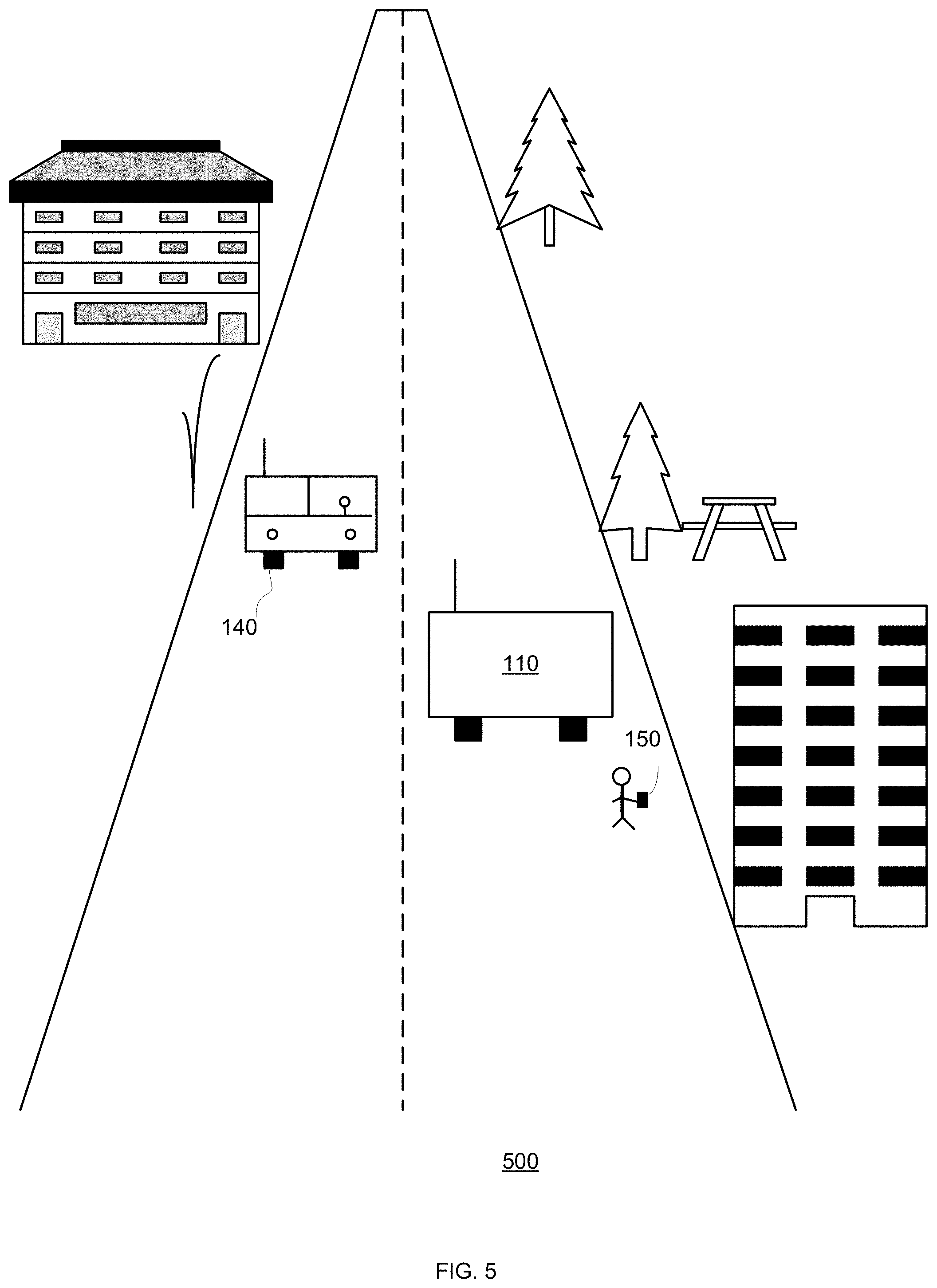
BRIEF DESCRIPTION OF THE DRAWINGS
[0006] The embodiments of the disclosure will be understood and appreciated more fully from the following detailed description, taken in conjunction with the drawings in which:
[0007] FIG. 1 illustrates an example of blind spots;
[0008] FIG. 2 illustrates an example of blind spots;
[0009] FIG. 3 illustrates an example of a method;
[0010] FIG. 4 illustrates an example of a method; and
[0011] FIG. 5 illustrates an example of an image.
DESCRIPTION OF EXAMPLE EMBODIMENTS
[0012] In the following detailed description, numerous specific details are set forth in order to provide a thorough understanding of the invention. However, it will be understood by those skilled in the art that the present invention may be practiced without these specific details. In other instances, well-known methods, procedures, and components have not been described in detail so as not to obscure the present invention.
[0013] The subject matter regarded as the invention is particularly pointed out and distinctly claimed in the concluding portion of the specification. The invention, however, both as to organization and method of operation, together with objects, features, and advantages thereof, may best be understood by reference to the following detailed description when read with the accompanying drawings.
[0014] It will be appreciated that for simplicity and clarity of illustration, elements shown in the figures have not necessarily been drawn to scale. For example, the dimensions of some of the elements may be exaggerated relative to other elements for clarity. Further, where considered appropriate, reference numerals may be repeated among the figures to indicate corresponding or analogous elements.
[0015] Because the illustrated embodiments of the present invention may for the most part, be implemented using electronic components and circuits known to those skilled in the art, details will not be explained in any greater extent than that considered necessary as illustrated above, for the understanding and appreciation of the underlying concepts of the present invention and in order not to obfuscate or distract from the teachings of the present invention.
[0016] Any reference in the specification to a method should be applied mutatis mutandis to a device or system capable of executing the method and/or to a non-transitory computer readable medium that stores instructions for executing the method.
[0017] Any reference in the specification to a system or device should be applied mutatis mutandis to a method that may be executed by the system, and/or may be applied mutatis mutandis to non-transitory computer readable medium that stores instructions executable by the system.
[0018] Any reference in the specification to a non-transitory computer readable medium should be applied mutatis mutandis to a device or system capable of executing instructions stored in the non-transitory computer readable medium and/or may be applied mutatis mutandis to a method for executing the instructions.
[0019] Any combination of any module or unit listed in any of the figures, any part of the specification and/or any claims may be provided.
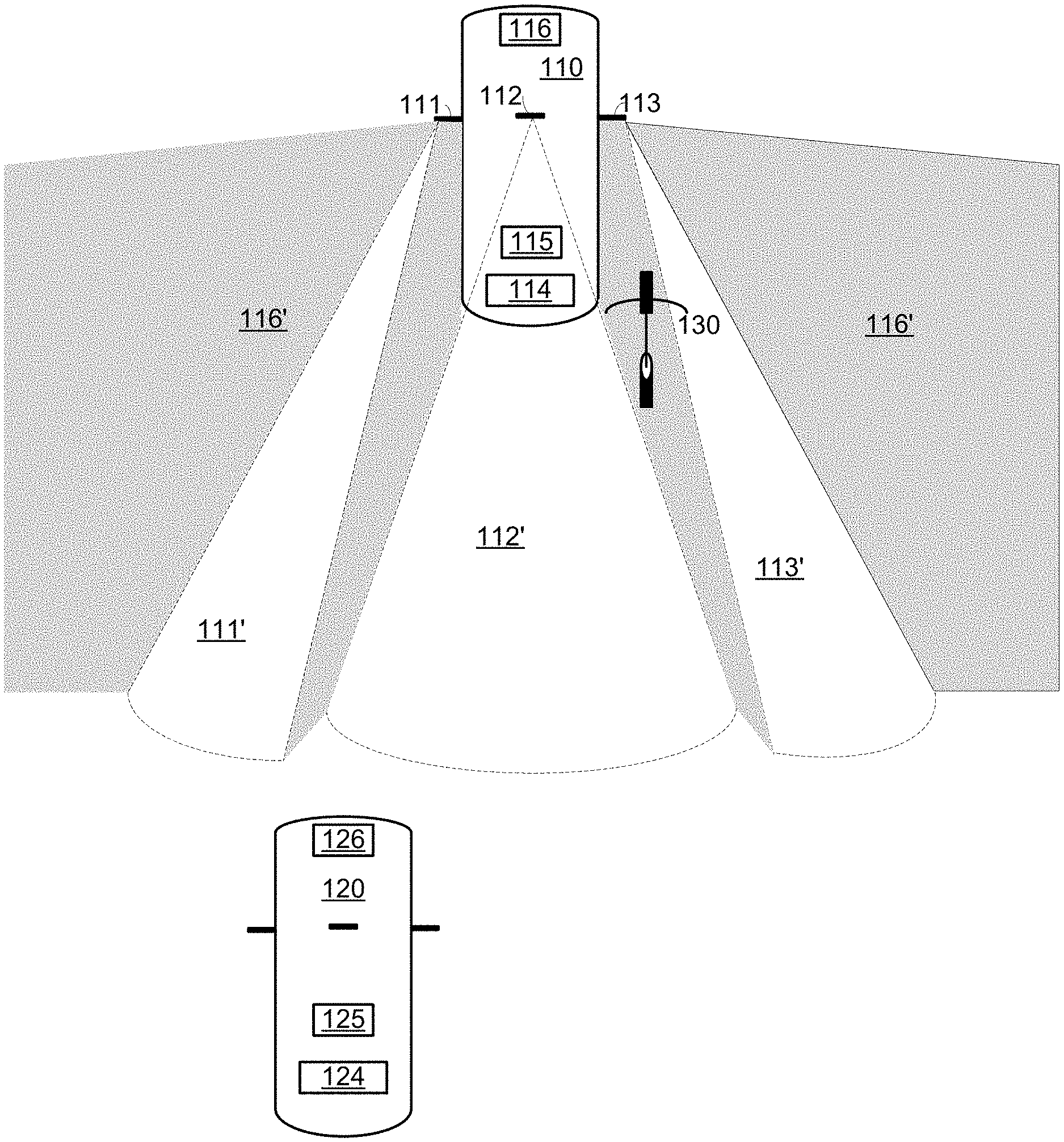
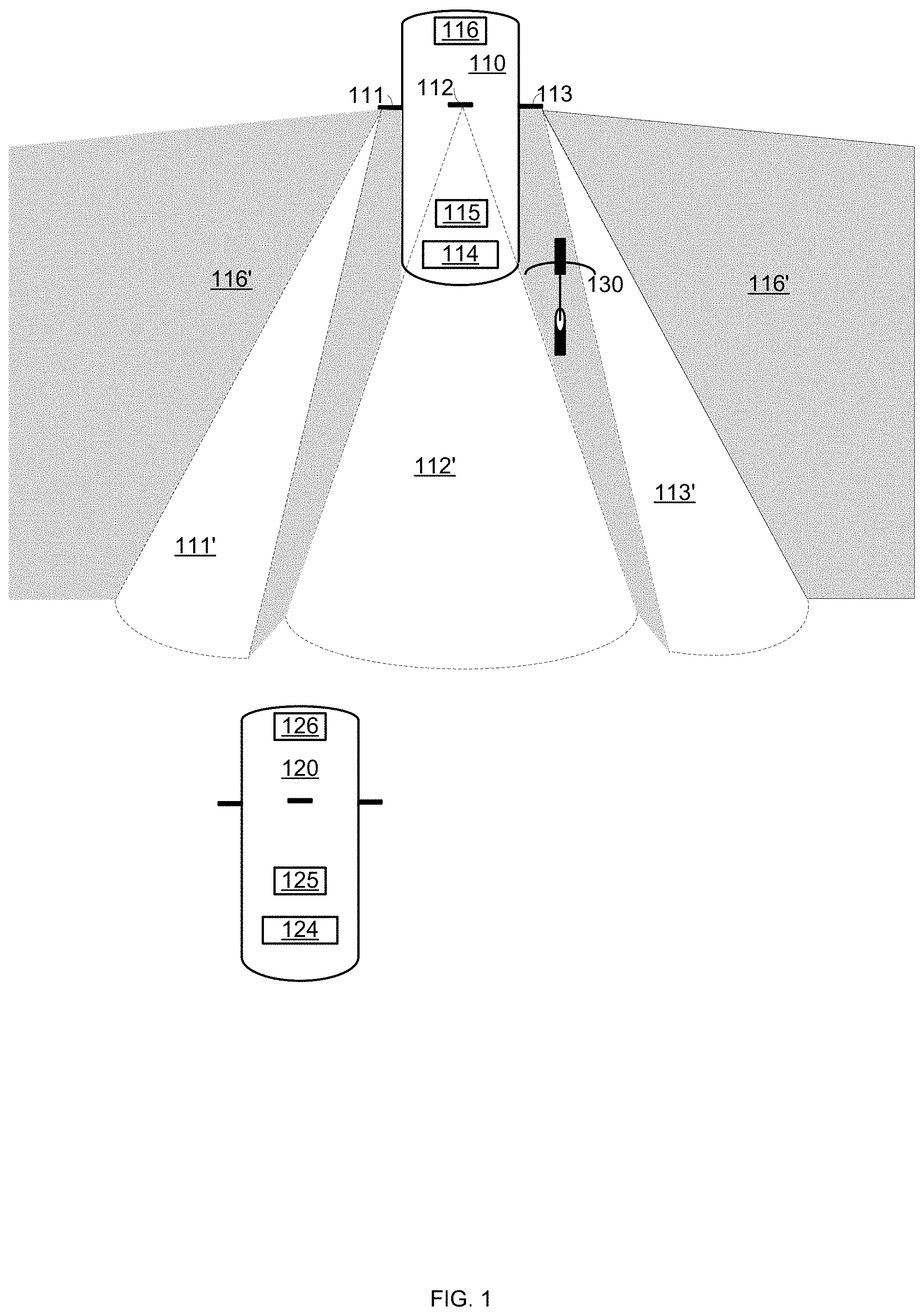
[0020] FIGS. 1 and 2 illustrate a first vehicle 110 that includes a left mirror 111, a front mirror 112, and a right mirror 113 that have coverage areas 111', 112' and 113' respectively. One or more areas outside these coverage areas may be regarded as a blind spot 116' of first vehicle.
[0021] In FIGS. 1 and 2, the second vehicle 120 is either located inside a blind spot or is about to enter the blind spot.
[0022] In FIG. 1, a bicycle 130 is also located within the blind spot of the first vehicle.
[0023] First vehicle 110 includes, in addition to mirrors 111, 112 and 113, one or more sensors 116, computerized system 115 and communication unit 114.
[0024] Second vehicle 120 includes, in addition to various mirrors, one or more sensors 126, computerized system 125 and communication unit 124.
[0025] The one or more sensors (116 and/or 126) may be one or more active sensors (that transmit radiation) and/or one or more passive sensors (that sense radiation without transmitting radiation). The one or more sensors may include, for example, radars, sonars, LIRARs, cameras, distanced sensors, inclination sensors, accelerometers, and the like. The radiation sensed by the one or more sensors may be of any frequency and/or bandwidth.
[0026] Communication unit (114 and/or 124) may be configured to communicate with other computerized systems and/or other communication units and/or may be configured to communicate with the driver, a road user and the like.
[0027] The communication unit may include a man machine interface, may include one or more loudspeaker, may include a vehicle multimedia unit may interface with a vehicle multimedia unit, may include an input/output unit such as a network interface card, universal serial bus (USB) port, disk reader, modem or transceiver that may be operative to use protocols such as are known in the art to communicate either directly, or indirectly, with other elements.
[0028] The computerized system (115 and/or 125) may include one or more processing circuitry. Each processing circuitry may be implemented as a central processing unit (CPU), and/or one or more other integrated circuits such as application-specific integrated circuits (ASICs), field programmable gate arrays (FPGAs), full-custom integrated circuits, etc., or a combination of such integrated circuits. The computerized system be configured to host or otherwise execute an autonomous driving module and/or an advanced driver assistance module. Each computerized system is configured to execute (in full or in part) any of the mentioned below methods.
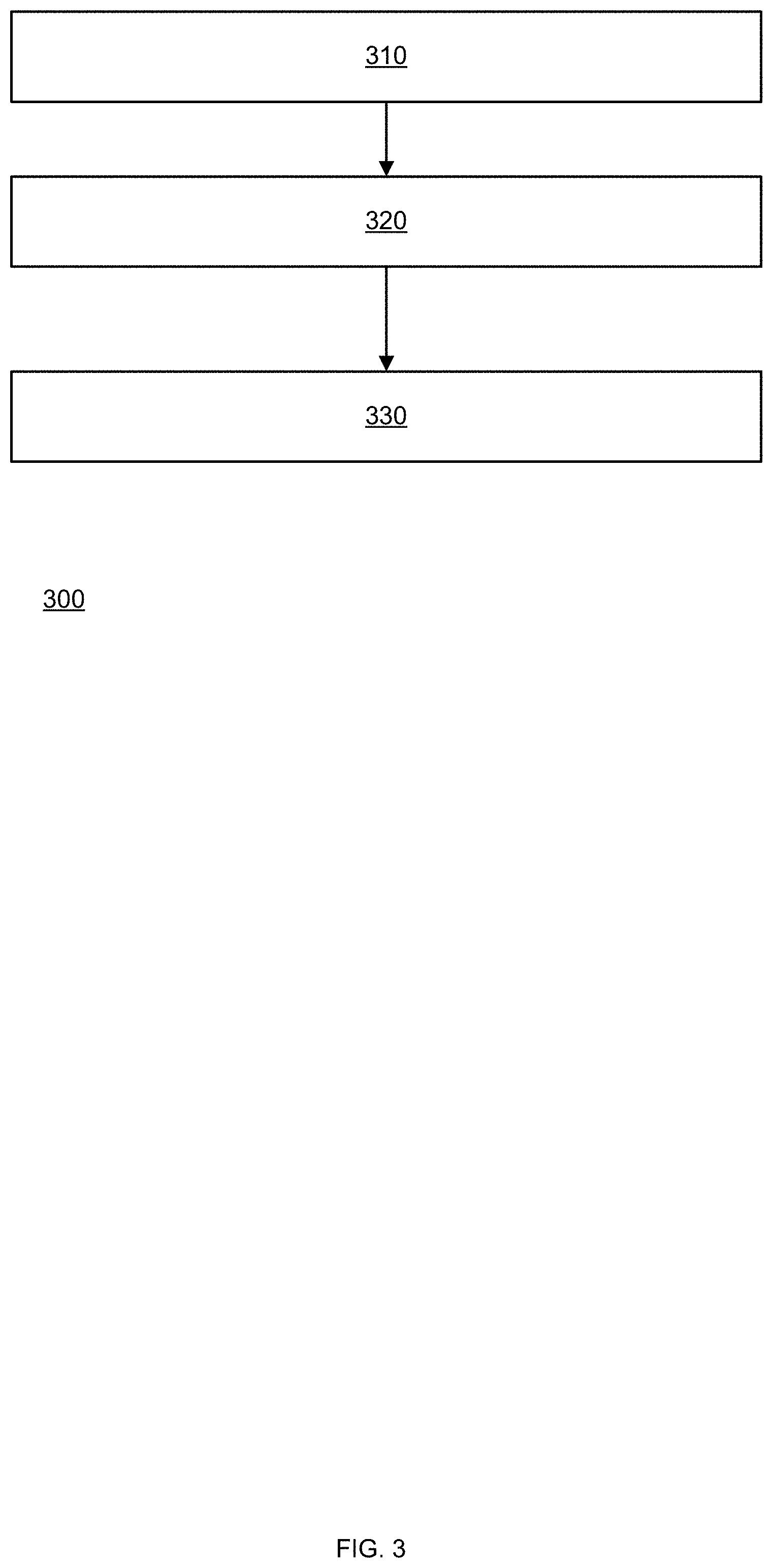
[0029] FIG. 3 illustrates an example of method 300.
[0030] Method 300 may be for estimating a potential blind spot event related to a potential blind spot of a first vehicle.
[0031] Method 300 may start by step 310 of detecting, using at least one sensor of a second vehicle, the first vehicle and a spatial relationship between the first vehicle and the second vehicle.
[0032] The detecting of the first vehicle may be executed by a first sensor of the second vehicle and the detecting of the spatial relationship between the first vehicle and the second vehicle may be executed by a second sensor of the second vehicle.
[0033] The first sensor and the second sensor may be the same sensor or may differ from each other.
[0034] The first sensor may be a camera and the second sensor may be a radar.
[0035] The least one sensor may be a camera. Step 310 may include detecting the spatial relationship between the first vehicle and the second vehicle by detecting an object of a known size, within an image of a scene captured by the camera, comparing the known size to a size of the object within the image. The object may be the first vehicle or may differ from the first vehicle.
[0036] The at least one sensor may be a camera, and the detecting the spatial relationship between the first vehicle and the second vehicle comprises detecting an optical phenomenon that occurs at a known distance from the camera. The optical phenomenon may be a blending of a bottom of a vehicle and a road.
[0037] The detection of the first vehicle may involve generating a signature of one or more images acquired by a sensor of the second vehicle, comparing the signature to clusters of signatures that are associated with different objects, finding one or more matching clusters (having one or more signatures that match the signature of the image) and when a matching signature is associated with a class, sub-class and the like determine the class or subclass of the first vehicle.
[0038] Step 310 may be followed by step 320 of estimating, based on at least one blind spot parameter of the first vehicle, an occurrence of the potential blind spot event.
[0039] The potential blind spot event may occur when (i) the second vehicle may be within a potential blind spot of the first vehicle (FIG. 1), or (ii) when the second vehicle may be about to enter the potential blind spot of the first vehicle (FIG. 2).
[0040] The at least one potential blind spot parameter of the first vehicle may include a class or subclass of vehicles that includes the first vehicle. The class may be selected out of a four-wheel vehicle and a two-wheel vehicle. The subclass may be selected out of a private car, a bus, a truck, a bicycle, a motorcycle. The subclass may also be selected out of the manufacturer of the vehicle, the model of the vehicle, a year of the vehicle, and the like.
[0041] The exact span of the blind spot may be dependent on various parameters some of which (referred to as additional potential blind spot parameters) may not be known to the second vehicle--for example--the actual orientation of at least one mirror of the first vehicle and a spatial relationship between a driver of the first vehicle and the at least one mirror of the first vehicle. The spatial relationship related to the driver may depend on the height of the driver, the location (for example--distances from the wheel) of the driver's seat, inclination of the driver seat, and the like.
[0042] Accordingly--step 320 may include generating a coarse estimate of the potential blind spot of the first vehicle.
[0043] The coarse estimate may ignore parameters not known yet to the second vehicle and/or may include assuming an existence of a worst case (or any other sub-optimal) potential blind spot scenario. This assumption may be based on the maximal size of the blind spot, or a coverage that does not include the second vehicle.
[0044] Step 320 may also include detecting at least one additional potential blind spot parameter and fine tuning the coarse estimate to provide a finer estimate of the potential blind spot of the first vehicle. The at least one additional potential blind spot parameter (for example orientation of the mirror may be detected using image processing or any other means. Additionally or alternatively, the at least one additional potential blind spot parameter may be provided by the first vehicle or even another system external to both vehicles.
[0045] Step 320 may include estimating of whether the second vehicle is about to enter the potential blind spot of the first vehicle by estimating future spatial relationships between the first vehicle and the second vehicle. This estimate of the future spatial relationship may include estimating the future trajectory of the first and second vehicles.
[0046] Step 320 may be also responsive to at least one environmental parameter related to an environment of the first vehicle.
[0047] The environmental parameter may be related to at least one out of an orientation of a path segment between the first and second vehicles, a curvature of the path segment, one or more obstacles positioned between the first and second vehicles and visibility conditions, and the like.
[0048] The at least one environmental parameter may be sensed by the second vehicle and/or may be provided to the second vehicle. For example, the orientation may be sensed by an orientation sensor, may be determined based on analysis of an image acquired by a camera of the second vehicle, and the like. The location of the second vehicle may be used to retrieve the environmental parameter from a database that maps various environmental parameters to locations. The database may be stored at the second vehicle or elsewhere.
[0049] Step 320 may be followed by step 330 of responding to the estimated occurrence of the potential blind spot event.
[0050] The responding may include at least one of the following: [0051] Sending a potential blind spot event alert to at least one of the driver of the first vehicle and the first vehicle. [0052] Receiving feedback from at least one of the driver of the first vehicle and the first vehicle about an accuracy of the estimating of the occurrence of the potential blind spot event. The feedback may be--the second vehicle is within a blind spot of the first vehicle, the second vehicle is outside the blind spot of the first vehicle, the second vehicle can be barely seen, and the like. The feedback may provide one or more additional potential blind spot parameters. [0053] Responding to the feedback. [0054] Responding to the feedback by requesting from at least one of the first vehicle and the driver of the first vehicle to alter at least one of a position and an orientation of at least one mirror of the first vehicle. The altering may be requested such as to reduce the risk related to the blind spot--for example changing speed and/or direction to increase the distance between the vehicles, allowing the second vehicle to exit a blind spot, slowing down the first vehicle until the second vehicle is far enough and/or outside the blind spot, and the like. [0055] Altering an autonomous driving pattern of the second vehicle. [0056] Generating by the second vehicle, a human perceivable potential blind spot event alert. [0057] Suggesting, by an advance driver assistance system, a suggested driving path based on the estimated occurrence of the potential blind spot event alert. The suggested path may be designed to reduce the risk related to the blind spot--for example changing speed and/or direction to increase the distance between the vehicles, allowing the second vehicle to exit a blind spot, slowing down the second vehicle until the second vehicle is far enough and/or outside the blind spot, and the like. [0058] Initiating a negotiation, between autonomous driving systems of the first and second vehicle, regarding an introduction of at least one change in an autonomous driving pattern of at least one vehicle of the first and second vehicles. The change may be determine using a by arbitration and/or distributed decision process. [0059] Participating in the negotiation. [0060] Introducing a negotiated change in an autonomous driving pattern of at least one vehicle of the first and second vehicles. [0061] Informing other computerized devices that share a road with the second vehicle about the estimated occurrence of the potential blind spot event. [0062] Informing other computerized devices that are within a proximity of the second vehicle about the estimated occurrence of the potential blind spot event. [0063] Alerting a road user about the blind spot.
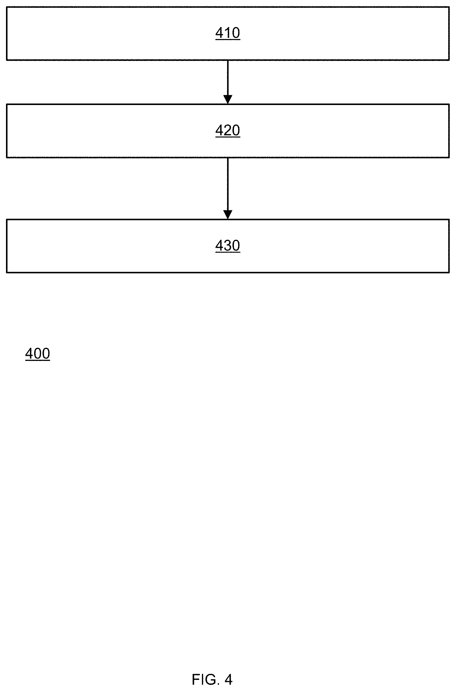
[0064] FIG. 4 illustrates an example of method 400.
[0065] Method 400 may be for estimating a potential blind spot event related to a potential blind spot of a first vehicle.
[0066] Method 400 may start by step 410 of detecting, using at least one sensor of a second vehicle, an existence of a road user, the first vehicle and a spatial relationship between the first vehicle and the road user.
[0067] Step 410 may use any of the sensors and/or operations applied during step 310.
[0068] Step 410 may be followed by step 420 of estimating, based on at least one blind spot parameter of the first vehicle, an occurrence of the potential blind spot event; wherein the potential blind spot event occurs when the road user is within a potential blind spot of the first vehicle or is about to enter the potential blind spot of the first vehicle.
[0069] Step 420 may apply any of the operations used in step 320.
[0070] Step 420 may be followed by step 430 of alerting at least one of the road user and the first vehicle about the estimated occurrence of the potential blind spot event.
[0071] The road user may be a pedestrian that walks, stands, drives a two wheel of single wheel vehicle, and the like.
[0072] The alert may be aimed, for example, to a rider of bicycle 130 of FIG. 1.
[0073] FIG. 5 illustrates an image 500 acquired by a sensor of the second vehicle 120.
[0074] The image illustrates various building, trees that surround a bi-directional road.
[0075] The image 500 also illustrates first vehicle 110, third vehicle 140, a pedestrian that has a mobile device 150.
[0076] The vehicles (first vehicle 110, second vehicle, third vehicle 140) and computerized devices such the mobile phone 150 may receive and/or transmit information related to the blind spot of any vehicle, road users and/or vehicle located within a blind spot and the like.
[0077] While the foregoing written description of the invention enables one of ordinary skill to make and use what is considered presently to be the best mode thereof, those of ordinary skill will understand and appreciate the existence of variations, combinations, and equivalents of the specific embodiment, method, and examples herein. The invention should therefore not be limited by the above described embodiment, method, and examples, but by all embodiments and methods within the scope and spirit of the invention as claimed.
[0078] In the foregoing specification, the invention has been described with reference to specific examples of embodiments of the invention. It will, however, be evident that various modifications and changes may be made therein without departing from the broader spirit and scope of the invention as set forth in the appended claims.
[0079] Moreover, the terms "front," "back," "top," "bottom," "over," "under" and the like in the description and in the claims, if any, are used for descriptive purposes and not necessarily for describing permanent relative positions. It is understood that the terms so used are interchangeable under appropriate circumstances such that the embodiments of the invention described herein are, for example, capable of operation in other orientations than those illustrated or otherwise described herein.
[0080] Furthermore, the terms "assert" or "set" and "negate" (or "deassert" or "clear") are used herein when referring to the rendering of a signal, status bit, or similar apparatus into its logically true or logically false state, respectively. If the logically true state is a logic level one, the logically false state is a logic level zero. And if the logically true state is a logic level zero, the logically false state is a logic level one.
[0081] Those skilled in the art will recognize that the boundaries between logic blocks are merely illustrative and that alternative embodiments may merge logic blocks or circuit elements or impose an alternate decomposition of functionality upon various logic blocks or circuit elements. Thus, it is to be understood that the architectures depicted herein are merely exemplary, and that in fact many other architectures may be implemented which achieve the same functionality.
[0082] Any arrangement of components to achieve the same functionality is effectively "associated" such that the desired functionality is achieved. Hence, any two components herein combined to achieve a particular functionality may be seen as "associated with" each other such that the desired functionality is achieved, irrespective of architectures or intermedial components. Likewise, any two components so associated can also be viewed as being "operably connected," or "operably coupled," to each other to achieve the desired functionality.
[0083] Furthermore, those skilled in the art will recognize that boundaries between the above described operations merely illustrative. The multiple operations may be combined into a single operation, a single operation may be distributed in additional operations and operations may be executed at least partially overlapping in time. Moreover, alternative embodiments may include multiple instances of a particular operation, and the order of operations may be altered in various other embodiments.
[0084] Also for example, in one embodiment, the illustrated examples may be implemented as circuitry located on a single integrated circuit or within a same device. Alternatively, the examples may be implemented as any number of separate integrated circuits or separate devices interconnected with each other in a suitable manner.
[0085] However, other modifications, variations and alternatives are also possible. The specifications and drawings are, accordingly, to be regarded in an illustrative rather than in a restrictive sense.
[0086] In the claims, any reference signs placed between parentheses shall not be construed as limiting the claim. The word `comprising` does not exclude the presence of other elements or steps then those listed in a claim. Furthermore, the terms "a" or "an," as used herein, are defined as one or more than one. Also, the use of introductory phrases such as "at least one" and "one or more" in the claims should not be construed to imply that the introduction of another claim element by the indefinite articles "a" or "an" limits any particular claim containing such introduced claim element to inventions containing only one such element, even when the same claim includes the introductory phrases "one or more" or "at least one" and indefinite articles such as "a" or "an." The same holds true for the use of definite articles. Unless stated otherwise, terms such as "first" and "second" are used to arbitrarily distinguish between the elements such terms describe. Thus, these terms are not necessarily intended to indicate temporal or other prioritization of such elements. The mere fact that certain measures are recited in mutually different claims does not indicate that a combination of these measures cannot be used to advantage.
[0087] While certain features of the invention have been illustrated and described herein, many modifications, substitutions, changes, and equivalents will now occur to those of ordinary skill in the art. It is, therefore, to be understood that the appended claims are intended to cover all such modifications and changes as fall within the true spirit of the invention.
[0088] It is appreciated that various features of the embodiments of the disclosure which are, for clarity, described in the contexts of separate embodiments may also be provided in combination in a single embodiment. Conversely, various features of the embodiments of the disclosure which are, for brevity, described in the context of a single embodiment may also be provided separately or in any suitable sub-combination.
[0089] It will be appreciated by persons skilled in the art that the embodiments of the disclosure are not limited by what has been particularly shown and described hereinabove. Rather the scope of the embodiments of the disclosure is defined by the appended claims and equivalents thereof.
* * * * *
D00000
D00001
D00002
D00003
D00004
D00005
XML
uspto.report is an independent third-party trademark research tool that is not affiliated, endorsed, or sponsored by the United States Patent and Trademark Office (USPTO) or any other governmental organization. The information provided by uspto.report is based on publicly available data at the time of writing and is intended for informational purposes only.
While we strive to provide accurate and up-to-date information, we do not guarantee the accuracy, completeness, reliability, or suitability of the information displayed on this site. The use of this site is at your own risk. Any reliance you place on such information is therefore strictly at your own risk.
All official trademark data, including owner information, should be verified by visiting the official USPTO website at www.uspto.gov. This site is not intended to replace professional legal advice and should not be used as a substitute for consulting with a legal professional who is knowledgeable about trademark law.