Unified Building Management System With Mechanical Room Controls
Harder; Patrick E. ; et al.
U.S. patent application number 16/655739 was filed with the patent office on 2020-04-23 for unified building management system with mechanical room controls. This patent application is currently assigned to Johnson Controls Technology Company. The applicant listed for this patent is Johnson Controls Technology Company. Invention is credited to Patrick E. Harder, Nicole Ann Madison, Michael J. Zummo.
| Application Number | 20200125084 16/655739 |
| Document ID | / |
| Family ID | 70280573 |
| Filed Date | 2020-04-23 |


View All Diagrams
| United States Patent Application | 20200125084 |
| Kind Code | A1 |
| Harder; Patrick E. ; et al. | April 23, 2020 |
UNIFIED BUILDING MANAGEMENT SYSTEM WITH MECHANICAL ROOM CONTROLS
Abstract
A building management system including building equipment operable to affect a variable state or condition of a building and a control system including a processing circuit. The processing circuit is configured to receive asset data relating to operation of the building equipment. The processing circuit is configured to identify a building device of the building equipment in a fault state based on the asset data. The processing circuit is configured to generate a work order in response to identifying the building device in the fault state. The work order indicates a required maintenance action and a maintenance time window. The processing circuit is configured to automatically populate fields of the work order based on the fault state. The processing circuit is configured to provide the work order to a user device.
| Inventors: | Harder; Patrick E.; (Hartland, WI) ; Madison; Nicole Ann; (Milwaukee, WI) ; Zummo; Michael J.; (Milwaukee, WI) | ||||||||||
| Applicant: |
|
||||||||||
|---|---|---|---|---|---|---|---|---|---|---|---|
| Assignee: | Johnson Controls Technology
Company Auburn Hills MI |
||||||||||
| Family ID: | 70280573 | ||||||||||
| Appl. No.: | 16/655739 | ||||||||||
| Filed: | October 17, 2019 |
Related U.S. Patent Documents
| Application Number | Filing Date | Patent Number | ||
|---|---|---|---|---|
| 62746939 | Oct 17, 2018 | |||
| Current U.S. Class: | 1/1 |
| Current CPC Class: | G05B 23/0283 20130101; G05B 2219/2642 20130101; G06Q 10/06316 20130101; G05B 15/02 20130101; A47C 9/10 20130101; A47C 4/04 20130101 |
| International Class: | G05B 23/02 20060101 G05B023/02; G05B 15/02 20060101 G05B015/02; G06Q 10/06 20060101 G06Q010/06 |
Claims
1. A building management system comprising: building equipment operable to affect a variable state or condition of a building; a control system comprising a processing circuit configured to: receive asset data relating to operation of the building equipment; identify a building device of the building equipment in a fault state based on the asset data; generate a work order in response to identifying the building device in the fault state, the work order indicating a required maintenance action and a maintenance time window; automatically populate a plurality of fields of the work order based on the fault state; and provide the work order to a user device.
2. The building management system of claim 1, the processing circuit further configured to schedule access permissions for a technician based on the work order.
3. The building management system of claim 1, the processing circuit further configured to: retrieve troubleshooting instructions related to the building device; and provide the troubleshooting instructions to the user device; wherein the work order is generated responsive to an indication that a user is unable to fix the fault state based on the troubleshooting instructions.
4. The building management system of claim 1, wherein the fault state is identified based on a determination that the building is not achieving a mode, the mode corresponding to at least one of: an operational mission for the building; a job-to-be-done in the building; or an event occurring in the building.
5. The building management system of claim 1, the processing circuit further configured to: generate a maintenance alert indicating the fault state; and provide the maintenance alert to the user device.
6. The building management system of claim 1, wherein at least a portion of the work order is automatically populated based on the asset data.
7. The building management system of claim 1, the processing circuit further configured to: log maintenance information provided by a technician, the maintenance information describing an operating state of the building device; and predict a change in a mode of the building based on the maintenance information.
8. A method for maintaining building equipment, the method comprising: receiving asset data relating to operation of the building equipment, the building equipment operable to affect a variable state or condition of a building; identifying a building device of the building equipment in a fault state based on the asset data; generating a work order in response to identifying the building device in the fault state, the work order indicating a required maintenance action and a maintenance time window; automatically populating a plurality of fields of the work order based on the fault state and providing the work order to a user device.
9. The method of claim 8, further comprising scheduling access permissions for a technician based on the work order.
10. The method of claim 8, further comprising: retrieving troubleshooting instructions related to the building device; and providing the troubleshooting instructions to the user device; wherein the work order is generated responsive to an indication that a user is unable to fix the fault state based on the troubleshooting instructions.
11. The method of claim 8, wherein the fault state is identified based on a determination that the building is not achieving a mode, the mode corresponding to at least one of: an operational mission for the building; a job-to-be-done in the building; or an event occurring in the building.
12. The method of claim 8, further comprising: generating a maintenance alert indicating the fault state; and providing the maintenance alert to the user device.
13. The method of claim 8, wherein at least a portion of the work order is automatically populated based on the asset data.
14. The method of claim 8, further comprising: logging maintenance information provided by a technician, the maintenance information describing an operating state of the building device; and predicting a change in a mode of the building based on the maintenance information.
15. A building management system comprising: building equipment operable to affect a variable state or condition of a building; a control system comprising a processing circuit configured to: obtain a work order for the building equipment, the work order identifying a location of the building equipment and a time at which maintenance is to be performed on the building equipment; schedule access permissions for a service technician based on the work order, the access permissions authorizing the service technician to access the location of the building equipment at the time at which the maintenance is to be performed.
16. The building management system of claim 15, the processing circuit further configured to generate the work order in response identifying the building equipment is in a fault state.
17. The building management system of claim 15, the processing circuit further configured to: obtain information related to the building equipment from a knowledge base; identify the service technician at the location during the time at which the maintenance is to be performed; and provide the information related to the building equipment to the service technician in response to identifying the service technician.
18. The building management system of claim 15, the processing circuit further configured to: generate wayfinding information to facilitate guidance of the service technician to the building equipment; and provide the wayfinding information to a second user device of the service technician.
19. The building management system of claim 15, the processing circuit further configured to perform a pre-maintenance action based on the work order, the pre-maintenance action comprising at least one of: scheduling lighting equipment to be operated during the time at which the maintenance is to be performed; or scheduling heating, ventilation, or air conditioning (HVAC) equipment to operate during the time at which the maintenance is to be performed.
20. The building management system of claim 15, the processing circuit further configured to predict how the maintenance will affect a mode of the building, the mode corresponding to at least one of: an operational mission for the building; a job-to-be-done in the building; or an event occurring in the building.
Description
CROSS-REFERENCE TO RELATED PATENT APPLICATION
[0001] This application claims the benefit of and priority to U.S. Provisional Patent Application No. 62/746,939 filed Oct. 17, 2018, incorporated herein by reference in its entirety.
BACKGROUND
[0002] The present disclosure relates generally to building domain systems (BDSs), and in particular building domain systems that may be present in a mechanical room of a building. A BDS is, in general, a system configured to control, monitor, and manage devices in or around a building or building area. As used herein, "devices" includes any building equipment, devices, apparatuses, sensors, etc. that provide measurements or data relating to a space or that can be controlled to change the condition of a space (e.g., light level, locked/unlocked, temperature, humidity). Accordingly, as used herein "devices" includes HVAC equipment (e.g., air handling units, chillers), thermostats, light fixtures, locks, sensors (detectors for smoke, heat, gas, flames, carbon monoxide, glass breaks, motion, and light; sensor that measure temperature, humidity, carbon dioxide, ambient light, and occupancy; presence/identity sensors (e.g., card readers, RFID receivers); cameras (e.g., video capture, image capture) and microphones), and other apparatuses (e.g., sound systems, blinds, appliances, garage doors, beds, televisions). Devices may also be referred to herein as environmental control assets.
[0003] Conventionally, a BDS is a domain-specific system that manages equipment of a particular building domain, for example a HVAC system, a security system, a lighting system, or a fire alerting system. Although in some cases multiple domain-specific systems have been placed in communication with one another as discussed below, such integrated systems do not capture the full potential of interoperability, functionality, and interdependence between building devices.
[0004] Furthermore, conventional BDS are focused on particular domains and types of devices, rather than the missions and functions of a place (e.g., a building, a campus) or a space (e.g., a floor, room, hallway, etc. included in a place) or the events occurring at such spaces and places. A disconnect therefore exists in conventional systems between the way occupants think about and utilize spaces and places and the way BDS are operated and controlled. Additionally, the collection of data from sensors and other data sources in conventional BDS places substantial limits and restrictions on the usefulness of that data, which may prevent users from acquiring the information needed for successful energy management, maintenance, or other building management and planning decision-making.
SUMMARY
[0005] One implementation of the present disclosure is a building management system, according to some embodiments. The building management system includes building equipment operable to affect a variable state or condition of a building, according to some embodiments. The building management system includes a control system including a processing circuit, according to some embodiments. The processing circuit is configured to receive asset data relating to operation of the building equipment, according to some embodiments. The processing circuit is configured to identify a building device of the building equipment in a fault state based on the asset data, according to some embodiments. The processing circuit is configured to generate a work order in response to identifying the building device in the fault state, according to some embodiments. The work order indicates a required maintenance action and a maintenance time window, according to some embodiments. The processing circuit is configured to automatically populate fields of the work order based on the fault state, according to some embodiments. The processing circuit is configured to provide the work order to a user device, according to some embodiments.
[0006] In some embodiments, the processing circuit is further configured to schedule access permissions for a technician based on the work order.
[0007] In some embodiments, the processing circuit is further configured to retrieve troubleshooting instructions related to the building device. The processing circuit further configured to provide the troubleshooting instructions to the user device, according to some embodiments. The work order is generated responsive to an indication that a user is unable to fix the fault state based on the troubleshooting instructions, according to some embodiments.
[0008] In some embodiments, the fault state is identified based on a determination that the building is not achieving a mode. The mode corresponds to at least one of an operational mission for the building, a job-to-be-done in the building, or an event occurring in the building, according to some embodiments.
[0009] In some embodiments, the processing circuit is further configured to generate a maintenance alert indicating the fault state. The processing circuit is further configured to provide the maintenance alert to the user device, according to some embodiments.
[0010] In some embodiments, at least a portion of the work order is automatically populated based on the asset data.
[0011] In some embodiments, the processing circuit is further configured to log maintenance information provided by a technician. The maintenance information describes an operating state of the building device, according to some embodiments. The processing circuit is further configured to predict a change in a mode of the building based on the maintenance information, according to some embodiments.
[0012] Another implementation of the present disclosure is a method for maintaining building equipment, according to some embodiments. The method includes receiving asset data relating to operation of the building equipment, according to some embodiments. The building equipment is operable to affect a variable state or condition of a building, according to some embodiments. The method includes identifying a building device of the building equipment in a fault state based on the asset data, according to some embodiments. The method includes generating a work order in response to identifying the building device in the fault state, according to some embodiments. The work order indicates a required maintenance action and a maintenance time window, according to some embodiments. The method includes automatically populating fields of the work order based on the fault state, according to some embodiments. The method includes providing the work order to a user device, according to some embodiments.
[0013] In some embodiments, the method includes scheduling access permissions for a technician based on the work order.
[0014] In some embodiments, the method includes retrieving troubleshooting instructions related to the building device. The method includes providing the troubleshooting instructions to the user device, according to some embodiments. The work order is generated responsive to an indication that a user is unable to fix the fault state based on the troubleshooting instructions, according to some embodiments.
[0015] In some embodiments, the fault state is identified based on a determination that the building is not achieving a mode. The mode corresponds to at least one of an operational mission for the building, a job-to-be-done in the building, or an event occurring in the building, according to some embodiments.
[0016] In some embodiments, the method includes generating a maintenance alert indicating the fault state. The method includes providing the maintenance alert to the user device, according to some embodiments.
[0017] In some embodiments, at least a portion of the work order is automatically populated based on the asset data.
[0018] In some embodiments, the method includes logging maintenance information provided by a technician. The maintenance information describes an operating state of the building device, according to some embodiments. The method includes predicting a change in a mode of the building based on the maintenance information, according to some embodiments.
[0019] Another implementation of the present disclosure is a building management system, according to some embodiments. The building management system includes building equipment operable to affect a variable state or condition of a building, according to some embodiments. The building management system includes a control system including a processing circuit, according to some embodiments. The processing circuit is configured to obtain a work order for the building equipment, according to some embodiments. The work order identifies a location of the building equipment and a time at which maintenance is to be performed on the building equipment, according to some embodiments. The processing circuit is configured to schedule access permissions for a service technician based on the work order, according to some embodiments. The access permissions authorize the service technician to access the location of the building equipment at the time at which the maintenance is to be performed, according to some embodiments.
[0020] In some embodiments, the processing circuit is further configured to generate the work order in response identifying the building equipment is in a fault state.
[0021] In some embodiments, the processing circuit is further configured to obtain information related to the building equipment from a knowledge base. The processing circuit is further configured to identify the service technician at the location during the time at which the maintenance is to be performed, according to some embodiments. The processing circuit is further configured to provide the information related to the building equipment to the service technician in response to identifying the service technician, according to some embodiments.
[0022] In some embodiments, the processing circuit is further configured to generate wayfinding information to facilitate guidance of the service technician to the building equipment. The processing circuit is further configured to provide the wayfinding information to a second user device of the service technician, according to some embodiments.
[0023] In some embodiments, the processing circuit is further configured to perform a pre-maintenance action based on the work order. The pre-maintenance action includes at least one of scheduling lighting equipment to be operated during the time at which the maintenance is to be performed or scheduling heating, ventilation, or air conditioning (HVAC) equipment to operate during the time at which the maintenance is to be performed, according to some embodiments.
[0024] In some embodiments, the processing circuit is further configured to predict how the maintenance will affect a mode of the building. The mode corresponds to at least one of an operational mission for the building, a job-to-be-done in the building, or an event occurring in the building, according to some embodiments.
[0025] This summary is illustrative only and is not intended to be in any way limiting. Other aspects, inventive features, and advantages of the devices or processes described herein will become apparent in the detailed description set forth herein, taken in conjunction with the accompanying figures, wherein like reference numerals refer to like elements.
BRIEF DESCRIPTION OF THE DRAWINGS
[0026] Various objects, aspects, features, and advantages of the disclosure will become more apparent and better understood by referring to the detailed description taken in conjunction with the accompanying drawings, in which like reference characters identify corresponding elements throughout. In the drawings, like reference numbers generally indicate identical, functionally similar, and/or structurally similar elements.
[0027] FIG. 1 is a drawing of a building equipped with a HVAC system, according to some embodiments.
[0028] FIG. 2 is a block diagram of a waterside system which can be used to serve the heating or cooling loads of the building of FIG. 1, according to some embodiments.
[0029] FIG. 3 is a block diagram of an airside system which can be used to serve the heating or cooling loads of the building of FIG. 1, according to some embodiments.
[0030] FIG. 4A is a diagram illustrating the concepts of occupants, spaces, places, and devices, according to some embodiments.
[0031] FIG. 4B is a visualization of spaces and places, according to some embodiments.
[0032] FIG. 4C is an example of a conventional collection of building domain systems for a building, according to some embodiments.
[0033] FIG. 5A is a block diagram of a conventional set of building domain systems.
[0034] FIG. 5B is a block diagram of a conventional integration system for use with the building domain systems of FIG. 5A.
[0035] FIG. 6 is a diagram of a unified building management system with space control, according to some embodiments.
[0036] FIG. 7A is a block diagram of a unified control architecture for building equipment including a unified control engine, according to some embodiments.
[0037] FIG. 7B is a block diagram of the unified control engine of FIG. 7A in greater detail and including a maintenance module, according to some embodiments.
[0038] FIG. 7C is a block diagram of the maintenance module of FIG. 7B in greater detail, according to some embodiments.
[0039] FIG. 8A is an illustration of an overview view in a mobile application for use with the UBMS of FIGS. 6-7C, according to some embodiments.
[0040] FIG. 8B is an illustration detailing the illustration of FIG. 8A in further detail, according to some embodiments.
[0041] FIG. 9 is an illustration of a technician access view in a mobile application for use with the UBMS of FIGS. 6-7C, according to some embodiments.
[0042] FIG. 10 is an illustration of an edit contact view in a mobile application for use with the UBMS of FIGS. 6-7C, according to some embodiments.
[0043] FIG. 11 is an illustration of a permissions menus screen in a mobile application for use with the UBMS of FIGS. 6-7C, according to some embodiments.
[0044] FIG. 12 is an illustration of a mobile application features screen in a mobile application for use with the UBMS of FIGS. 6-7C, according to some embodiments.
[0045] FIG. 13 is an illustration of a locations permissions screen in a mobile application for use with the UBMS of FIGS. 6-7C, according to some embodiments.
[0046] FIG. 14 is an illustration of an access type screen in a mobile application for use with the UBMS of FIGS. 6-7C, according to some embodiments.
[0047] FIG. 15 is an illustration of a history view in a mobile application for use with the UBMS of FIGS. 6-7C, according to some embodiments.
[0048] FIG. 16 is an illustration of a schedule view in a mobile application for use with the UBMS of FIGS. 6-7C, according to some embodiments.
[0049] FIG. 17 is an illustration of an equipment view in a mobile application for use with the UBMS of FIGS. 6-7C, according to some embodiments.
[0050] FIG. 18A is an illustration of an expanded equipment card in a mobile application for use with the UBMS of FIGS. 6-7C, according to some embodiments.
[0051] FIG. 18B is an illustration of the expanded equipment card of FIG. 18A in greater detail, according to some embodiments.
[0052] FIG. 19 is an illustration of a knowledge base view in a mobile application for use with the UBMS of FIGS. 6-7C, according to some embodiments.
[0053] FIG. 20 is an illustration of a live knowledge base view in a mobile application for use with the UBMS of FIGS. 6-7C, according to some embodiments.
[0054] FIG. 21 is an illustration of a video stream view in a mobile application for use with the UBMS of FIGS. 6-7C, according to some embodiments.
[0055] FIG. 22 is an illustration of an alert view in a mobile application for use with the UBMS of FIGS. 6-7C, according to some embodiments.
[0056] FIG. 23 is an illustration of a troubleshooting view in a mobile application for use with the UBMS of FIGS. 6-7C, according to some embodiments.
[0057] FIG. 24 is an illustration of a work order request view in a mobile application for use with the UBMS of FIGS. 6-7C, according to some embodiments.
[0058] FIG. 25 is an illustration of a work order view in a mobile application for use with the UBMS of FIGS. 6-7C, according to some embodiments.
[0059] FIG. 26 is an illustration of a notes view in a mobile application for use with the UBMS of FIGS. 6-7C, according to some embodiments.
[0060] FIG. 27 is a flowchart of an example process of servicing devices of building equipment using the mobile application of FIGS. 8-26, according to some embodiments.
DETAILED DESCRIPTION
Introduction
[0061] People experience the spaces and places with which they engage in many ways: they work in spaces and places, reside in spaces and places, entertain themselves in spaces and places, shop in spaces and places, heal in spaces and places, dine in spaces and places, etc., experiencing all aspects of life in spaces and places. People think about spaces and places from the perspective of these experiences: a space or a place is somewhere an event occurs, a job must be done, a mission is supported, or some other experience plays out. In the ideal scenario, spaces, places, and the devices that serve the spaces and places would seamlessly and intuitively support the goals, missions, needs, desires, and perspectives of the people experiencing those spaces and places.
[0062] However, a disconnect exists between conventional building domain systems and the way people see spaces and places. Conventional devices, and systems of conventional devices, are often designed, chosen, and operated to focus primarily on the needs of the devices or systems themselves. A space or place is typically served by many devices across many domains, for example HVAC, fire, access, security, lighting, etc. The devices of the various domains are typically independent of one another, with devices and systems for each domain designed, chosen, and installed with the focus on the particular domain. Each of the various building domain systems may be operated independently, achieving a limited impact on the way a person experiences a space or place. Interactions with each domain are often limited to terms familiar to that domain (e.g., HVAC systems are set to temperature setpoints, lighting systems turn on and off lights, access systems lock and unlock doors), rather than in terms of what missions, goals, tasks, or events that an occupant desires a space or place to support. This results in disjointed, time-consuming, and unfulfilling experiences for people attempting to use a space or place.
[0063] The systems and methods described herein provide an innovative space- and place-centric approach that seamlessly aligns the way that people think about and experience spaces and places with the way that devices are controlled to support those experiences. The space- and place-centric approach may eliminate the barriers between the way people conceive of the missions of spaces and places, the jobs people need to complete in spaces and places, events that occur in spaces and places, etc. and the way that the devices that support those missions, jobs, events, etc. are chosen, designed, and controlled. The way that data is collected and processed relating to spaces and places, for example utilization metrics about spaces and places, may be similarly aligned with the missions and purposes of the spaces and places.
[0064] These advantages may be supported across any of the extensive variety of types of spaces and places with which people engage, tuned precisely to the missions and purposes of each particular space or place. For example, offices, office buildings, retail stores, warehouses, hospitals, patient rooms, operating rooms, waiting rooms, movie theaters, stadiums, arenas, malls, restaurants, hotels, apartments, factories, gymnasiums, classrooms, libraries, and/or any other type of space or place experienced by people may have its own purposes, missions, and jobs and events to support. The systems and methods described herein may contemplate all such spaces and places and may allow for efficient installation, updates, data collection and controls of devices well-suited for all such spaces and places and any combination of spaces and places.
[0065] Several features, summarized here and described in detail below with reference to the FIGURES, facilitate this space- and place-centric approach. To start, the sensors, networks, controllers, and other systems in the space- and place-centric approach may be domain-agnostic. That is, the systems and methods disclosed herein may eliminate the barriers between domain-specific systems, unifying all domains into a unified control system. Although the space- and place-centric approach may be implemented by integrating or otherwise facilitating communication between building domain systems, in some embodiments the approach is implemented using a unified building management system (UBMS). A UBMS may place all devices, sensors, etc. in a single system, eliminating barriers between domains and facilitating the exchange of data, controls, resources, etc. across all components of the UBMS. All sensors and devices that can be used to influence the way a person experiences a space or place may be unified in the UBMS. Thus, the UBMS may allow all devices serving a space or place to be controlled as a unified group that supports a mission, purpose, job, or event for the space or place.
[0066] Next, space profiles for the spaces and place profiles for the places can be used to facilitate the space- and place-centric approach. Each space or place profile may define many aspects of how the space or place is designed, controlled, perceived, and used, and may include all or substantially all of the information needed to control the space or place across domains and to collect and analyze data relating to the space or place. Space and place profiles can be designed and created based on how people experience each space and place, including the jobs people need to accomplish in a space or place, the missions the space or place supports, the purpose of a space or place, and/or events that may occur in the space or place. Different types of spaces and places may have different space or place profiles specific to that type of space or place, such that each space or place profile reflects the needs of that particular space or place.
[0067] Space and place profiles can be easily loaded onto control systems for spaces and places (e.g., onto a DBMS) to easily and efficiently align systems and devices with the purposes, missions, goals, etc. of the spaces and places represented by the profiles. Further, space and place profiles can be easily updated or switched to respond to changes to the space or place. For example, when a place is remodeled or reimagined such that a space that was formerly used as one type of space (e.g., an office) is reimagined as another type of space (e.g., a conference room), the space profile for that space can be easily switched from an "office" space profile to a "conference room" space profile. Space-centric control can thus be immediately aligned with the new purposes, missions, functions, and goals of the space. Space and place profiles thereby provide efficient and adaptable support for the space- and place-centric control approach described herein.
[0068] Each of the space profiles that can be assigned to a given space may be associated with a particular type of space or use of the space (e.g., office, conference room, cafeteria, etc.) and may include settings that facilitate a function or purpose of that type of space or use of the space. The settings provided by a given space profile may include settings for various types of equipment that serve the space across multiple equipment domains (e.g., settings for HVAC equipment, settings for lighting equipment, settings for A/V equipment, etc.). For example, the "office" space profile may include a first set of settings for HVAC equipment, lighting equipment, A/V equipment, and/or other types of equipment that serve the space that cause the equipment to be controlled in a manner that facilitates usage of the space as an office. Conversely, the "conference room" space profile may include a second set of settings for the HVAC equipment, lighting equipment, A/V equipment, and/or other types of equipment that serve the space that cause the equipment to be controlled in a manner that facilitates usage of the space as a conference room.
[0069] Each space profile for a given space may include a different set of settings for some or all of the equipment that serve that space. For example, the HVAC settings defined by an "office" space profile may cause HVAC equipment that serve the space provide sufficient airflow and/or heating or cooling for a relatively small number of people occupying the space (e.g., one person or a small group of people), whereas the HVAC settings defined by a "conference room" space profile may cause the same HVAC equipment to provide a relatively greater amount of airflow or heating or cooling for a greater number of people occupying the space (e.g., 2-10 people or a larger group of people). Similarly, the lighting settings defined by the "office" space profile may cause lighting equipment that light the space to provide constant lighting for the space, whereas the lighting settings defined by the "conference room" space profile may cause the lighting equipment to light the space only when the space is occupied. As another example, the occupancy settings defined by the "office" space profile may provide a first occupancy threshold for evaluating whether the space is fully occupied (e.g., one person may fully occupy an office), whereas the occupancy settings defined by the "conference room" space profile may provide a second occupancy threshold for evaluating whether the space is fully occupied (e.g., 10 people may fully occupy a conference room).
[0070] In response to switching from the "office" space profile to the "conference room" space profile, the settings provided by the "office" space profile may be replaced with the settings provided by the "conference room" space profile. For example, a space controller may distribute the settings associated with the "conference room" space profile to some or all of the equipment that serve the space, causing the equipment to operate in accordance with the settings defined by the "conference room" space profile. The settings can be distributed to any type of equipment that serve the space, even if the equipment operate across multiple different equipment domains (e.g., HVAC, lighting, A/V, security, IT, etc.).
[0071] Next, the space- and place-centric approach allows for control of devices based on modes for the spaces and places. In some embodiments, each mode corresponds to an operational mission for the space or place, a job-to-be-done in the space or place, or an event occurring in the space or place. Each mode may correspond to settings or other commands for the devices in a space or place that control those devices to support the operational mission, the job to be done, or the event. The modes for a space or place may be predefined (e.g., by a user, automatically by a system, etc.) and stored in the space or place profile for the space or place profile, and, like the space or place profile, can be updated, supplemented, altered, or otherwise easily changed as needed to adapt to new uses of a space or place. Mode changes may be triggered based on input from various sensors, specialty systems, user inputs, detected events, etc. to allow for efficient transition between modes precisely as needed by occupants of a space or place. Accordingly, spaces and places, and all devices across all domains, can be controlled to enable people to use the spaces and places in many different ways.
[0072] Furthermore, spaces and places may be composable (i.e., a place may be made up of spaces, a space may include spaces, and a place may include places), and the profiles and the modes for the spaces and places can be tuned to take these interrelationships into account. For example, as described in detail herein, a change in mode in one space may be communicated to related spaces and places to allow those spaces and places to adjust as needed to the change. Spaces, places, sensors, devices, and other systems contemplated herein may be coordinated in an amorphous web such that everything works seamlessly together to support people's use of all spaces and places.
[0073] Another feature of the space- and place-centric approach described herein is the unification of sensors that serve spaces and places. In traditional systems, each building domain system includes domain-specific sensors that provide data that can only be used by devices of the corresponding domain. To achieve functionality in a second domain that could benefit from the same information captured by that data, additional sensors specific to the second domain traditionally must be installed to serve the second domain. Further, in traditional systems, data from the domains is siloed and cannot be easily combined to verify measurements, generate cross-domain metrics, and provide controls that allow a person to view the space in terms of the purposes or missions of the space.
[0074] In the space- and place-centric approach described herein, sensors may be domain-agnostic and may provide data as needed by the space or place regardless of the domain traditionally associated with any sensor or any type of data provided by that sensor. All sensors can be combined in a unified sensor network that provides the data needed by any device, and all devices can use data from any sensor. The devices can be controlled using aggregated data in a way that is agnostic of the source of the data. The sensors best suited for any given space may be used in that space, and different types of sensors can be used within a space or across multiple spaces and places to provide similar data attributes that are used by the devices. Data provided across spaces, including data from a variety of types of sensors, can also be used to enable place-level features like wayfinding or asset tracking. Sensor data from sensor traditionally associated with different domains can be unified into single data points or data series, for example by using one sensor to verify the accuracy of a measurement from another sensor. New sensors can be installed in a plug-and-play manner that allows them to automatically be included in any data calculations, control logic, or application that would benefit from the data from the new sensors. The unification of domain-agnostic sensors described herein thereby greatly enhances and supports the space- and place-centric approach.
[0075] In addition to the sources of data being tuned to the needs of each space, the metrics generated for each space may also be chosen to best capture the way people think about particular spaces and places. For example, the space- and place-based approach may facilitate the generation of actual-usage-based space utilization metrics. Different types of spaces can be utilized in different ways, such that the utilization of each space can be quantified in a way that aligns with the way people think about usage of that space. For example, usage of a warehouse may be conceptualized by users based on the volume of the space taken up by stored goods, usage of a restroom may be conceptualized based on the resources (e.g., water, soap, paper towels, toilet paper) consumed by people in the space, and usage of a conference room may be conceptualized based on how many people are in the space, among other possibilities. By aggregating data from across any sensors or other data sources for a space or place and applying that data as suitable for calculating a utilization metric that aligns with how people conceptualize usage of a space, the space- and place-centric approach facilitates the calculation of actual-usage-based utilization metrics. These actual-usage-based utilization metrics can then support improved resource management, energy management, maintenance/restocking/etc. planning, or developing other building management strategies.
[0076] Furthermore, as described in detail below, the systems and methods described herein may provide a graphical user interface on a user device (e.g., smartphone, tablet) that allows a user to view and leverage data in the UBMS across various devices. As described in detail below, one embodiment of such a graphical user interface is a mobile application for use by maintenance technicians tasked with monitoring and servicing mechanical rooms in buildings. The combination of the UBMS, a space-centric approach, and the mobile application features described in detail here provide a uniquely-powerful tool for use in monitoring and servicing building equipment in mechanical rooms.
[0077] Together, these and other features may seamlessly align the way people think about and experience spaces and places with the way that devices are controlled to support those experiences and the way data is collected relating to those thoughts and experiences. Space- and place-centric control of spaces and places may eliminate translation barriers between the way people conceive of the missions of spaces and places, the jobs people need to complete in spaces and places, events that occur in spaces and places, etc. and the way that devices that support those missions, jobs, events, etc. are chosen, designed, and controlled. The systems and methods described herein can thereby enable intuitive, efficient, and fulfilling interactions between people and spaces and places. Many such features are described in detail in U.S. patent application Ser. No. 15/952,173, filed Apr. 12, 2018, incorporated by reference herein in its entirety, and U.S. patent application Ser. No. 16/132,045, filed Sep. 14, 2018, incorporated by reference herein in its entirety.
Building and HVAC System
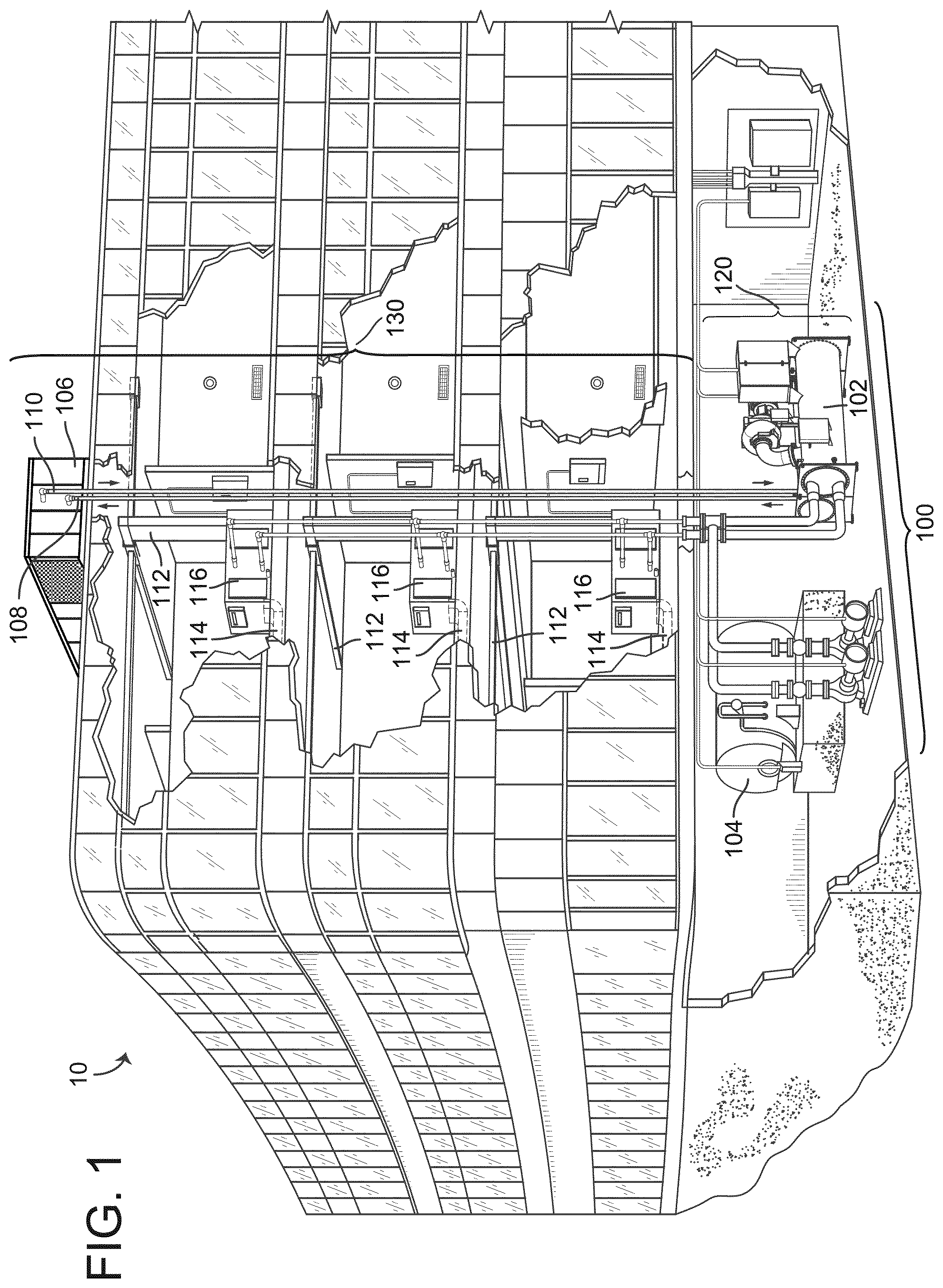
[0078] Referring now to FIG. 1, a perspective view of a building 10 is shown. Building 10 is served by a BMS. A BMS is, in general, a system of devices configured to control, monitor, and manage equipment in or around a building or building area. A BMS can include, for example, a HVAC system, a security system, a lighting system, a fire alerting system, and/or any other system that is capable of managing building functions or devices, or any combination thereof.
[0079] The BMS that serves building 10 includes a HVAC system 100. HVAC system 100 can include a plurality of HVAC devices (e.g., heaters, chillers, air handling units, pumps, fans, thermal energy storage, etc.) configured to provide heating, cooling, ventilation, or other services for building 10. For example, HVAC system 100 is shown to include a waterside system 120 and an airside system 130. Waterside system 120 may provide a heated or chilled fluid to an air handling unit of airside system 130. Airside system 130 may use the heated or chilled fluid to heat or cool an airflow provided to building 10. An exemplary waterside system and airside system which can be used in HVAC system 100 are described in greater detail with reference to FIGS. 2-3.
[0080] HVAC system 100 is shown to include a chiller 102, a boiler 104, and a rooftop air handling unit (AHU) 106. Waterside system 120 may use boiler 104 and chiller 102 to heat or cool a working fluid (e.g., water, glycol, etc.) and may circulate the working fluid to AHU 106. In various embodiments, the HVAC devices of waterside system 120 can be located in or around building 10 (as shown in FIG. 1) or at an offsite location such as a central plant (e.g., a chiller plant, a steam plant, a heat plant, etc.). The working fluid can be heated in boiler 104 or cooled in chiller 102, depending on whether heating or cooling is required in building 10. Boiler 104 may add heat to the circulated fluid, for example, by burning a combustible material (e.g., natural gas) or using an electric heating element. Chiller 102 may place the circulated fluid in a heat exchange relationship with another fluid (e.g., a refrigerant) in a heat exchanger (e.g., an evaporator) to absorb heat from the circulated fluid. The working fluid from chiller 102 and/or boiler 104 can be transported to AHU 106 via piping 108.
[0081] AHU 106 may place the working fluid in a heat exchange relationship with an airflow passing through AHU 106 (e.g., via one or more stages of cooling coils and/or heating coils). The airflow can be, for example, outside air, return air from within building 10, or a combination of both. AHU 106 may transfer heat between the airflow and the working fluid to provide heating or cooling for the airflow. For example, AHU 106 can include one or more fans or blowers configured to pass the airflow over or through a heat exchanger containing the working fluid. The working fluid may then return to chiller 102 or boiler 104 via piping 110.
[0082] Airside system 130 may deliver the airflow supplied by AHU 106 (i.e., the supply airflow) to building 10 via air supply ducts 112 and may provide return air from building 10 to AHU 106 via air return ducts 114. In some embodiments, airside system 130 includes multiple variable air volume (VAV) units 116. For example, airside system 130 is shown to include a separate VAV unit 116 on each floor or zone of building 10. VAV units 116 can include dampers or other flow control elements that can be operated to control an amount of the supply airflow provided to individual zones of building 10. In other embodiments, airside system 130 delivers the supply airflow into one or more zones of building 10 (e.g., via supply ducts 112) without using intermediate VAV units 116 or other flow control elements. AHU 106 can include various sensors (e.g., temperature sensors, pressure sensors, etc.) configured to measure attributes of the supply airflow. AHU 106 may receive input from sensors located within AHU 106 and/or within the building zone and may adjust the flow rate, temperature, or other attributes of the supply airflow through AHU 106 to achieve setpoint conditions for the building zone.
Waterside System
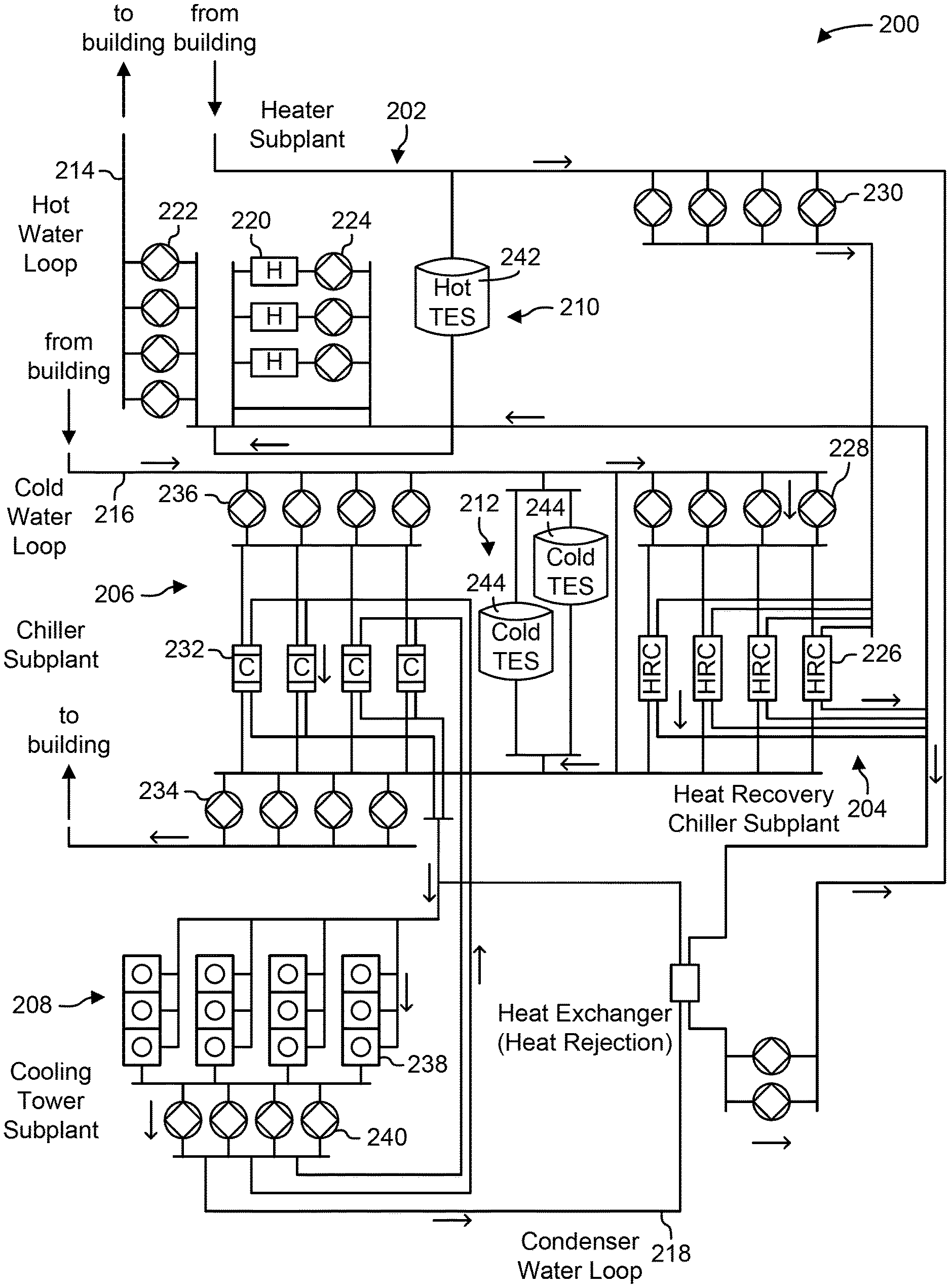
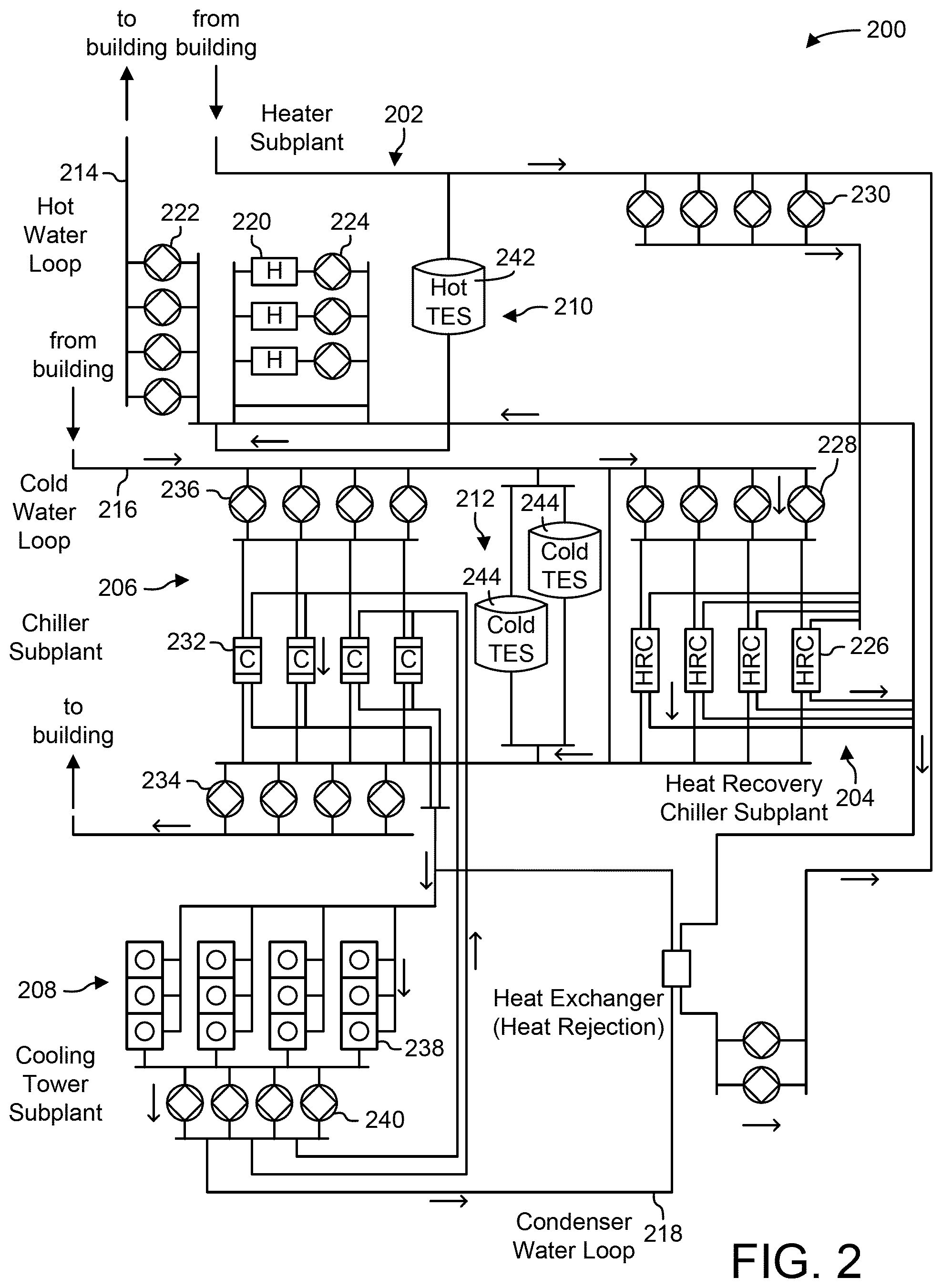
[0083] Referring now to FIG. 2, a block diagram of a waterside system 200 is shown, according to some embodiments. In various embodiments, waterside system 200 may supplement or replace waterside system 120 in HVAC system 100 or can be implemented separate from HVAC system 100. When implemented in HVAC system 100, waterside system 200 can include a subset of the HVAC devices in HVAC system 100 (e.g., boiler 104, chiller 102, pumps, valves, etc.) and may operate to supply a heated or chilled fluid to AHU 106. The HVAC devices of waterside system 200 can be located within building 10 (e.g., as components of waterside system 120) or at an offsite location such as a central plant.
[0084] In FIG. 2, waterside system 200 is shown as a central plant having a plurality of subplants 202-212. Subplants 202-212 are shown to include a heater subplant 202, a heat recovery chiller subplant 204, a chiller subplant 206, a cooling tower subplant 208, a hot thermal energy storage (TES) subplant 210, and a cold thermal energy storage (TES) subplant 212. Subplants 202-212 consume resources (e.g., water, natural gas, electricity, etc.) from utilities to serve thermal energy loads (e.g., hot water, cold water, heating, cooling, etc.) of a building or campus. For example, heater subplant 202 can be configured to heat water in a hot water loop 214 that circulates the hot water between heater subplant 202 and building 10. Chiller subplant 206 can be configured to chill water in a cold water loop 216 that circulates the cold water between chiller subplant 206 building 10. Heat recovery chiller subplant 204 can be configured to transfer heat from cold water loop 216 to hot water loop 214 to provide additional heating for the hot water and additional cooling for the cold water. Condenser water loop 218 may absorb heat from the cold water in chiller subplant 206 and reject the absorbed heat in cooling tower subplant 208 or transfer the absorbed heat to hot water loop 214. Hot TES subplant 210 and cold TES subplant 212 may store hot and cold thermal energy, respectively, for subsequent use.
[0085] Hot water loop 214 and cold water loop 216 may deliver the heated and/or chilled water to air handlers located on the rooftop of building 10 (e.g., AHU 106) or to individual floors or zones of building 10 (e.g., VAV units 116). The air handlers push air past heat exchangers (e.g., heating coils or cooling coils) through which the water flows to provide heating or cooling for the air. The heated or cooled air can be delivered to individual zones of building 10 to serve thermal energy loads of building 10. The water then returns to subplants 202-212 to receive further heating or cooling.
[0086] Although subplants 202-212 are shown and described as heating and cooling water for circulation to a building, it is understood that any other type of working fluid (e.g., glycol, CO2, etc.) can be used in place of or in addition to water to serve thermal energy loads. In other embodiments, subplants 202-212 may provide heating and/or cooling directly to the building or campus without requiring an intermediate heat transfer fluid. These and other variations to waterside system 200 are within the teachings of the present disclosure.
[0087] Each of subplants 202-212 can include a variety of equipment configured to facilitate the functions of the subplant. For example, heater subplant 202 is shown to include a plurality of heating elements 220 (e.g., boilers, electric heaters, etc.) configured to add heat to the hot water in hot water loop 214. Heater subplant 202 is also shown to include several pumps 222 and 224 configured to circulate the hot water in hot water loop 214 and to control the flow rate of the hot water through individual heating elements 220. Chiller subplant 206 is shown to include a plurality of chillers 232 configured to remove heat from the cold water in cold water loop 216. Chiller subplant 206 is also shown to include several pumps 234 and 236 configured to circulate the cold water in cold water loop 216 and to control the flow rate of the cold water through individual chillers 232.
[0088] Heat recovery chiller subplant 204 is shown to include a plurality of heat recovery heat exchangers 226 (e.g., refrigeration circuits) configured to transfer heat from cold water loop 216 to hot water loop 214. Heat recovery chiller subplant 204 is also shown to include several pumps 228 and 230 configured to circulate the hot water and/or cold water through heat recovery heat exchangers 226 and to control the flow rate of the water through individual heat recovery heat exchangers 226. Cooling tower subplant 208 is shown to include a plurality of cooling towers 238 configured to remove heat from the condenser water in condenser water loop 218. Cooling tower subplant 208 is also shown to include several pumps 240 configured to circulate the condenser water in condenser water loop 218 and to control the flow rate of the condenser water through individual cooling towers 238.
[0089] Hot TES subplant 210 is shown to include a hot TES tank 242 configured to store the hot water for later use. Hot TES subplant 210 may also include one or more pumps or valves configured to control the flow rate of the hot water into or out of hot TES tank 242. Cold TES subplant 212 is shown to include cold TES tanks 244 configured to store the cold water for later use. Cold TES subplant 212 may also include one or more pumps or valves configured to control the flow rate of the cold water into or out of cold TES tanks 244.
[0090] In some embodiments, one or more of the pumps in waterside system 200 (e.g., pumps 222, 224, 228, 230, 234, 236, and/or 240) or pipelines in waterside system 200 include an isolation valve associated therewith. Isolation valves can be integrated with the pumps or positioned upstream or downstream of the pumps to control the fluid flows in waterside system 200. In various embodiments, waterside system 200 can include more, fewer, or different types of devices and/or subplants based on the particular configuration of waterside system 200 and the types of loads served by waterside system 200.
Airside System
[0091] Referring now to FIG. 3, a block diagram of an airside system 300 is shown, according to some embodiments. In various embodiments, airside system 300 may supplement or replace airside system 130 in HVAC system 100 or can be implemented separate from HVAC system 100. When implemented in HVAC system 100, airside system 300 can include a subset of the HVAC devices in HVAC system 100 (e.g., AHU 106, VAV units 116, ducts 112-114, fans, dampers, etc.) and can be located in or around building 10. Airside system 300 may operate to heat or cool an airflow provided to building 10 using a heated or chilled fluid provided by waterside system 200.
[0092] In FIG. 3, airside system 300 is shown to include an economizer-type air handling unit (AHU) 302. Economizer-type AHUs vary the amount of outside air and return air used by the air handling unit for heating or cooling. For example, AHU 302 may receive return air 304 from building zone 306 via return air duct 308 and may deliver supply air 310 to building zone 306 via supply air duct 312. In some embodiments, AHU 302 is a rooftop unit located on the roof of building 10 (e.g., AHU 106 as shown in FIG. 1) or otherwise positioned to receive both return air 304 and outside air 314. AHU 302 can be configured to operate exhaust air damper 316, mixing damper 318, and outside air damper 320 to control an amount of outside air 314 and return air 304 that combine to form supply air 310. Any return air 304 that does not pass through mixing damper 318 can be exhausted from AHU 302 through exhaust damper 316 as exhaust air 322.
[0093] Each of dampers 316-320 can be operated by an actuator. For example, exhaust air damper 316 can be operated by actuator 324, mixing damper 318 can be operated by actuator 326, and outside air damper 320 can be operated by actuator 328. Actuators 324-328 may communicate with an AHU controller 330 via a communications link 332. Actuators 324-328 may receive control signals from AHU controller 330 and may provide feedback signals to AHU controller 330. Feedback signals can include, for example, an indication of a current actuator or damper position, an amount of torque or force exerted by the actuator, diagnostic information (e.g., results of diagnostic tests performed by actuators 324-328), status information, commissioning information, configuration settings, calibration data, and/or other types of information or data that can be collected, stored, or used by actuators 324-328. AHU controller 330 can be an economizer controller configured to use one or more control algorithms (e.g., state-based algorithms, extremum seeking control (ESC) algorithms, proportional-integral (PI) control algorithms, proportional-integral-derivative (PID) control algorithms, model predictive control (MPC) algorithms, feedback control algorithms, etc.) to control actuators 324-328.
[0094] Still referring to FIG. 3, AHU 302 is shown to include a cooling coil 334, a heating coil 336, and a fan 338 positioned within supply air duct 312. Fan 338 can be configured to force supply air 310 through cooling coil 334 and/or heating coil 336 and provide supply air 310 to building zone 306. AHU controller 330 may communicate with fan 338 via communications link 340 to control a flow rate of supply air 310. In some embodiments, AHU controller 330 controls an amount of heating or cooling applied to supply air 310 by modulating a speed of fan 338.
[0095] Cooling coil 334 may receive a chilled fluid from waterside system 200 (e.g., from cold water loop 216) via piping 342 and may return the chilled fluid to waterside system 200 via piping 344. Valve 346 can be positioned along piping 342 or piping 344 to control a flow rate of the chilled fluid through cooling coil 334. In some embodiments, cooling coil 334 includes multiple stages of cooling coils that can be independently activated and deactivated (e.g., by AHU controller 330, by BMS controller 366, etc.) to modulate an amount of cooling applied to supply air 310.
[0096] Heating coil 336 may receive a heated fluid from waterside system 200 (e.g., from hot water loop 214) via piping 348 and may return the heated fluid to waterside system 200 via piping 350. Valve 352 can be positioned along piping 348 or piping 350 to control a flow rate of the heated fluid through heating coil 336. In some embodiments, heating coil 336 includes multiple stages of heating coils that can be independently activated and deactivated (e.g., by AHU controller 330, by BMS controller 366, etc.) to modulate an amount of heating applied to supply air 310.
[0097] Each of valves 346 and 352 can be controlled by an actuator. For example, valve 346 can be controlled by actuator 354 and valve 352 can be controlled by actuator 356. Actuators 354-356 may communicate with AHU controller 330 via communications links 358-360. Actuators 354-356 may receive control signals from AHU controller 330 and may provide feedback signals to controller 330. In some embodiments, AHU controller 330 receives a measurement of the supply air temperature from a temperature sensor 362 positioned in supply air duct 312 (e.g., downstream of cooling coil 334 and/or heating coil 336). AHU controller 330 may also receive a measurement of the temperature of building zone 306 from a temperature sensor 364 located in building zone 306.
[0098] In some embodiments, AHU controller 330 operates valves 346 and 352 via actuators 354-356 to modulate an amount of heating or cooling provided to supply air 310 (e.g., to achieve a setpoint temperature for supply air 310 or to maintain the temperature of supply air 310 within a setpoint temperature range). The positions of valves 346 and 352 affect the amount of heating or cooling provided to supply air 310 by cooling coil 334 or heating coil 336 and may correlate with the amount of energy consumed to achieve a desired supply air temperature. AHU 330 may control the temperature of supply air 310 and/or building zone 306 by activating or deactivating coils 334-336, adjusting a speed of fan 338, or a combination of both.
[0099] Still referring to FIG. 3, airside system 300 is shown to include a building management system (BMS) controller 366 and a client device 368. BMS controller 366 can include one or more computer systems (e.g., servers, supervisory controllers, subsystem controllers, etc.) that serve as system level controllers, application or data servers, head nodes, or master controllers for airside system 300, waterside system 200, HVAC system 100, and/or other controllable systems that serve building 10. BMS controller 366 may communicate with multiple downstream building systems or subsystems (e.g., HVAC system 100, a security system, a lighting system, waterside system 200, etc.) via a communications link 370 according to like or disparate protocols (e.g., LON, BACnet, etc.). In various embodiments, AHU controller 330 and BMS controller 366 can be separate (as shown in FIG. 3) or integrated. In an integrated implementation, AHU controller 330 can be a software module configured for execution by a processor of BMS controller 366.
[0100] In some embodiments, AHU controller 330 receives information from BMS controller 366 (e.g., commands, setpoints, operating boundaries, etc.) and provides information to BMS controller 366 (e.g., temperature measurements, valve or actuator positions, operating statuses, diagnostics, etc.). For example, AHU controller 330 may provide BMS controller 366 with temperature measurements from temperature sensors 362-364, equipment on/off states, equipment operating capacities, and/or any other information that can be used by BMS controller 366 to monitor or control a variable state or condition within building zone 306.
[0101] Client device 368 can include one or more human-machine interfaces or client interfaces (e.g., graphical user interfaces, reporting interfaces, text-based computer interfaces, client-facing web services, web servers that provide pages to web clients, etc.) for controlling, viewing, or otherwise interacting with HVAC system 100, its subsystems, and/or devices. Client device 368 can be a computer workstation, a client terminal, a remote or local interface, or any other type of user interface device. Client device 368 can be a stationary terminal or a mobile device. For example, client device 368 can be a desktop computer, a computer server with a user interface, a laptop computer, a tablet, a smartphone, a PDA, or any other type of mobile or non-mobile device. Client device 368 may communicate with BMS controller 366 and/or AHU controller 330 via communications link 372.
Spaces & Places
[0102] Referring now to FIG. 4A, a conceptual diagram 400 of some core elements of the space- and place-centric systems and methods described herein is shown, according to some embodiments. In FIG. 4A, occupants 402 are shown to occupy place 408. Occupants 402 may be any person who is in the place 408 and is not limited to individuals who operate the place 408, maintain the place 408, live in the place 408, work in the place 408, etc. Occupants 402 may occupy various spaces 404 within a place. The various spaces 404 of the building may be spaces such as an office space, a gym space, a cafe space, a lab space, patient rooms, nurses stations, waiting rooms, a classroom space, parking garage, and any other kinds of spaces that may be present in or around a place. The occupants 402 use the various spaces 404 in the place 408 for various uses, purposes, missions, tasks, jobs, situations, etc. The space- and place-centric systems and methods of the present disclosure align control of spaces and places with occupant's purposes and missions in utilizing the spaces and places.
[0103] Each physical space may have its own devices 406 and/or may share devices 406 with other spaces in the place 408. Devices 406 include devices across various domains, such as HVAC devices, security devices, lighting devices, access devices, fire devices, etc. The devices 406 may work together to achieve various outcomes in a place, as described in detail below. In general, devices 406 are controlled based on space profiles and place profiles. The place profiles may be a particular data structure that includes properties such as spaces profile for spaces 404 in the place 408, modes and mode logic for controlling devices 406 in the place, and other applications that enable uses for the place. Space profiles include indication of the type of space, modes for that type of space, and attributes of the space, among other features as described in detail below. As described in detail herein, place- and space-profiles can facilitate place- and space-based aggregation of sensor data and control of devices 406.
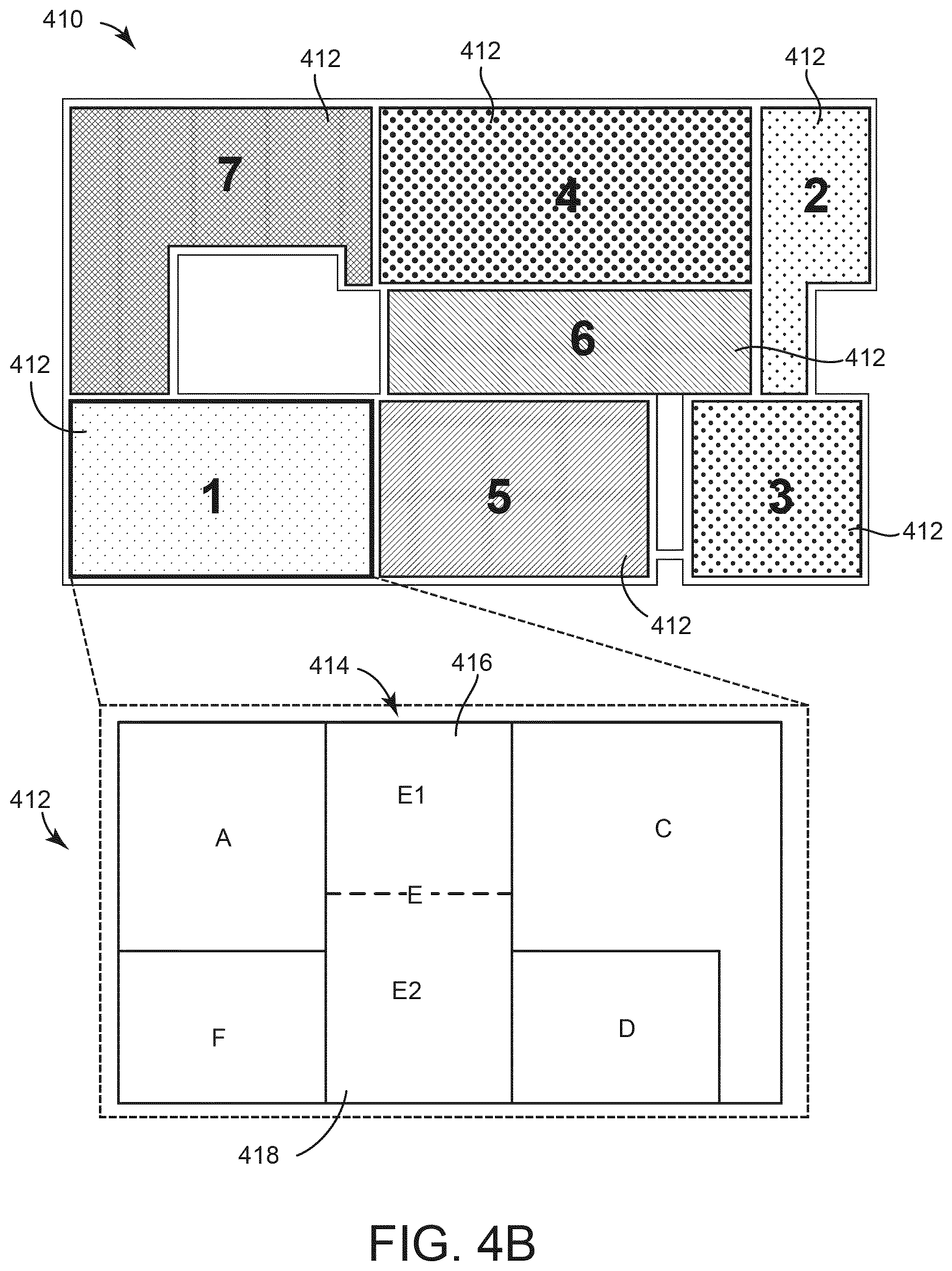
[0104] Referring now to FIG. 4B, a visualization of the concept of spaces and places is shown, according to some embodiments. A campus 410 is shown with seven buildings 412. In the nomenclature used herein, each building 412 can be considered a "place." The campus 410, made up of multiple places, may also be referred to as a "place". Each of the seven buildings 412 ("Building 1", "Building 2", etc.) include a variety of rooms, floors, or other divisions. As one example, FIG. 4B includes an expanded view 1604 of "Building 1" 412. The expanded view 1604 shows a variety of "spaces" (i.e., floors, areas, rooms, etc.) of "Building 1" 412. As illustrated by space E 414, spaces may be broken up into subspaces (in this example, subspace E1 416 and subspace E2 418 make up space E 414). These subspaces may be referred to as "spaces" herein.
[0105] A place is generally made up of spaces. The place may be referred to as a "parent" of a space if the space is in that place. That space is then a "child" of that place. For example space E 414 is a child of place "Building 1" 412, and "Building 1" 412 is the parent of space E 414. Because a space (e.g., space E) may be made up of spaces (e.g., spaces E1 416 and E2 418) and a place (e.g., campus 410) may be made up of places, a space may have a child and/or parent space and a place may have a child and/or parent place.
[0106] As used herein, the term "space or place" refers to any space or place where a system, component, method, etc. applies to either spaces or places. Spaces or places are typically fixed locations/areas (e.g., with an address, GPS coordinate, etc.) but may also include mobile spaces or places (e.g., a ship and rooms aboard the ship). Furthermore, while "space" or "place" may be used in describing the embodiments described herein, it should be understood that in many concepts described herein with reference to a space may also be applicable to a place.
Conventional Building Domain Systems and Control Architectures
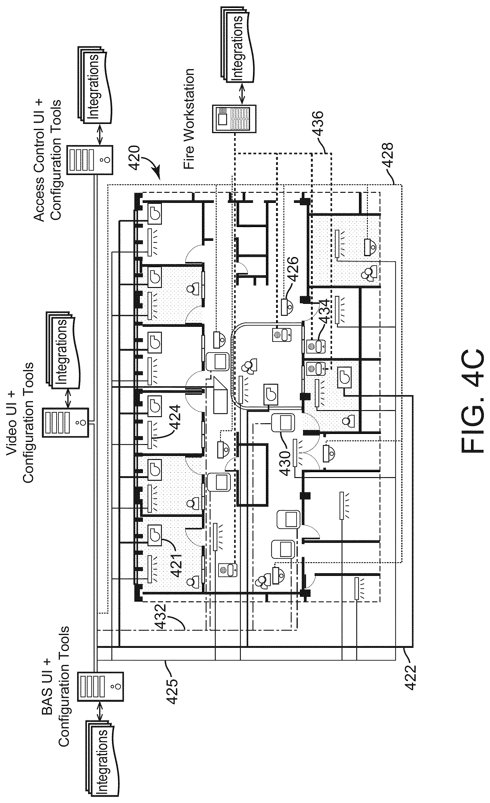
[0107] Referring now to FIG. 4C a diagram of five independently-operating conventional BDSs for a place 420 (e.g., a building and surrounding outdoor areas) is shown for the sake of background. More particularly, place 420 may include an HVAC system, a lighting system, an access system, a video system, and a fire system. In conventional BDSs, the systems mentioned above operate independently, resulting in widespread complexity. Each of the HVAC system, the lighting system, the access system, the video system, and the fire system have separate networks and cabling, controllers and servers, and user interfaces. For example, in the HVAC system, HVAC devices 421 are connected by HVAC cabling 422, while lighting devices 424 are connected by lighting cabling 425, video devices 426 are connected by video cabling 428, access devices 430 are connected by access cabling 432, and fire devices 434 are connected by fire cabling 436 in the respective systems. Even if wireless networks are used instead of physical cabling, the wireless networks supporting each building system are generally separate. Furthermore, different network protocols may be used by the various systems, for example LonWorks, MSTP, BACnet, ONVIF, etc., inhibiting interconnectivity. In sum, the systems of place 420 are implemented and installed as physically and electronically isolated systems in FIG. 4C. Limitations of such siloed systems are described with references to the following two figures.
[0108] Referring now to FIGS. 5A and 5B, existing control architectures are shown for the sake of comparison to the systems and methods described herein. FIG. 5A shows isolated ("siloed") control and equipment for each of three building domains in an isolated architecture 500. In a lighting system 514, lighting equipment 504 is controlled by lighting controller 502. In the HVAC system 516, HVAC equipment 508 is controlled by the HVAC controller 506. In the access system 518, access equipment 512 is controlled by an access controller 510. The lighting system 514, the HVAC system 516, and the access system 518 are entirely independent of one another. Thus, in the isolated architecture 500 of FIG. 5A, each building domain (i.e., each type of functionality provided to the building), is siloed and operates independently. Creating a desired condition in a space or place using the isolated architecture 500 requires separate interactions with each domain (i.e., lighting, HVAC, access).
[0109] FIG. 5B shows an integration architecture 550 that attempts to integrate the separate systems 514-518. An integration system 552 includes and integrated controller 554, a lighting integrator 556, an HVAC integrator 558, and an access integrator 560. The lighting integrator 556 translates data, control signals, etc. between a data model used by the integrated controller 554 and a lighting data model used by the lighting system 514. The HVAC integrator 558 translates data, control signals, etc. between a data model used by the integrated controller 554 and an HVAC data model used by the HVAC system 516. The access integrator 560 translates data, control signals, etc. between a data model used by the integrated controller 554 and an access data model used by the access system 518. The integration system 552 thereby relies on fragile translations, interfaces, integrations, etc. to provide some amount of interaction across building domains. However, the integration system 552 is prone to errors and breakdowns, for example caused by software updates in one system 514-518. Further, integration adds complexity, computation expenses, etc. to the operation of a building management system. The integration architecture 550 may therefore by unsatisfactory for users.
Unified Building Management System
[0110] Referring now to FIG. 6, a unified building management system (UBMS) 600 is shown for a place. The UBMS 600 includes HVAC devices 602, lighting devices 604, access devices 606, video devices 608, and fire devices 610 that serve multiple spaces in place 420. The HVAC devices 602, lighting devices 604, access devices 606, and video devices 608 are connected via a common network (e.g., common cabling, shared wireless network). Fire devices 610 may also be connected to the common network and/or may have a separate network 614 as shown to provide extra reliability or redundancy for safety-critical functions and/or to comply with regulatory requirements. The devices 602-610 are communicable using a common protocol (e.g., BACnet, MSTP, LonWorks, TCP/IP) and are connected to a common server 601. The common network 612 saves costs, materials, time etc. in installation, operation, and maintenance as compared to the multitude of networks used for the combination of BDSs shown in FIG. 4C. The common network 612 and the common protocol also facilitate other beneficial interconnectivity, interdependence, redundancy, etc. for the UBMS 600, as described in detail below.
[0111] In the UBMS 600, devices 602-610 are primarily associated with spaces in place 420 that the devices serve. Place 420 in the example of FIG. 6 is a medical facility that includes the following spaces: patient rooms 613, data center room 615, nurses' station 616, waiting room 617, outdoor area 618, and doctor's office 619. As opposed to dealing with what domain a device belongs to, the UBMS 600 focuses on spaces, the mission of a space, and the people that use those spaces. For example, patient rooms 613 are shown with missions "heal, treat, care," as well as with an HVAC device 602 and lighting device 604 for each, while the outdoor area 618 has the mission "park" and is served by a video device 608. The UBMS 600 manages and controls the devices that serve each space (e.g., each patient room 213) in order to fulfill the mission of the space. Facilitated by the removal of complexities and barriers found in simultaneous use of multiple BDSs, the UBMS 600 coordinates devices independent of domain to align devices, people, spaces, places, and missions. Further details and advantages of this approach are discussed in U.S. Provisional Patent Application No. 62/485,282 filed Apr. 13, 2017, and U.S. Provisional Patent Application No. 62/560,567 filed Sep. 19, 2017. The entire disclosures of both these patent applications are incorporated by reference herein.
[0112] Each of the physical spaces of place 420 is shown to include its own group of devices. Each group of devices may communicate via their own network. In this regard, each group of devices may independently service the particular space that they are in. Each group of devices may communicate via the common network. However, if one of the groups loses connection with the common network and/or common server 601 goes offline, that group of devices may be self-sufficient and may operate without connection to the server 601 and the rest of UBMS 600.
[0113] Server 601 may be any computing system, server, controller, laptop computer, desktop computer, and/or other computing device or system that communicates with the device groups of the physical spaces (e.g., patient rooms 613) of place 420. Since each device group includes access systems, security systems, and HVAC systems, server 601 may communicate with and/or control each of the systems with no integration between various controllers and/or discrete systems. Further, there may be a single operating interface 652 that can run on a user device, server 601, and/or communicate with server 601. Similarly, there may also be a single configuration interface 650 that may run on a user device, server 601, and/or communicate with server 601. Operating interface 652 may be the same as configuration interface 650. Since the device groups of place 420 include a plurality of systems, operating interface 652 and/or configuration interface 650 may be a unification of devices across domains and allow a user to operate and/or configure the plurality of devices (e.g., devices for HVAC, security, access, video, lighting, fire etc.).
[0114] The devices (e.g., HVAC, fire, security, lighting, access, fire etc.) of UBMS 600 may be part of a single unified product offering. Further, the system may be module and the installation of UBMS 600 may be a single module installation. UBMS 600 may be integrated with partner systems and may include "deep" integrations between the systems of place 420 and partner systems. Further, the UBMS 600 may include standard open protocols and APIs that allow for third party systems to be integrated with UBMS 600.
Unified Control Architecture with Spaces and Places
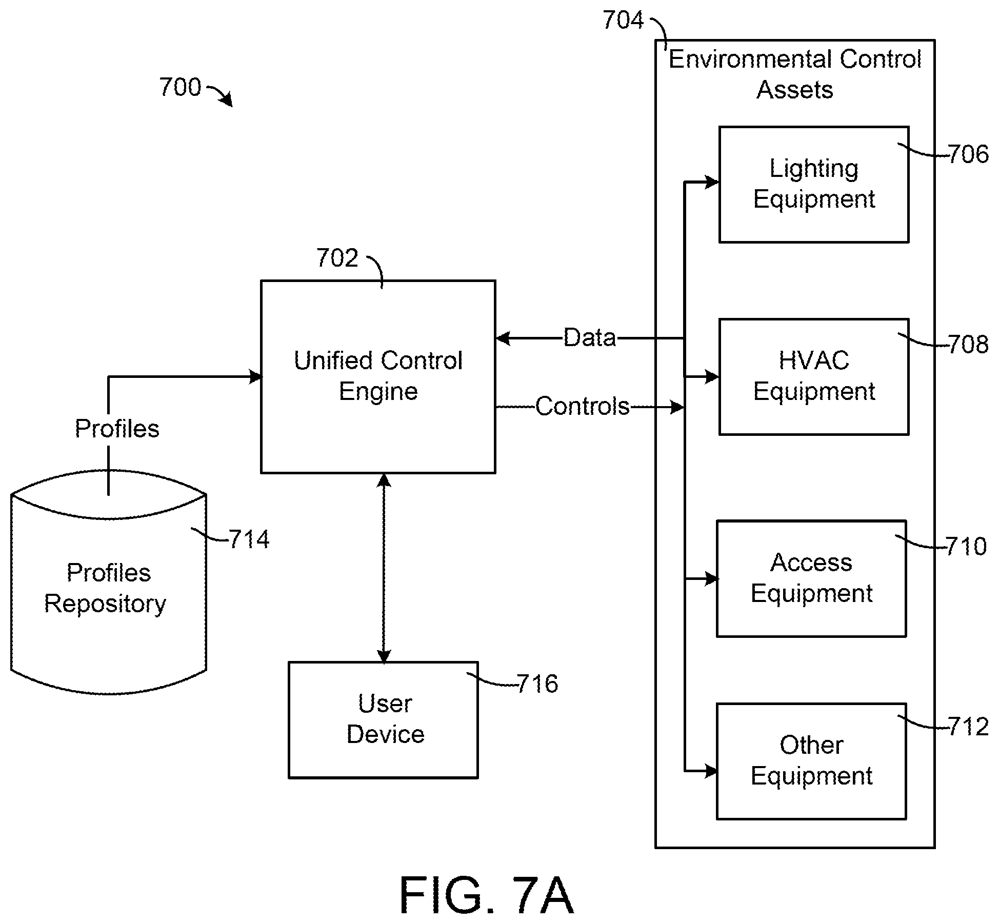
[0115] Referring now to FIG. 7A, a block diagram of a unified control architecture 700 is shown, according to some embodiments. The unified control architecture 700 includes a unified control engine 702 that controls environmental control assets 704. The unified control engine 702 may be implemented on server 601 of FIG. 6, may be implemented a space- or place-controller, may be implemented in the cloud, may be distributed among multiple computing resources (e.g., including a user device 716), or may be implemented in some other way. The unified control architecture 700 overcomes the shortcomings of the isolated architecture 500 and the integration architecture 550.
[0116] The unified control architecture 700 is also shown to include a user device 716. The user device 716 may be one or more personal computing devices associated with a user or occupant of a space or place, for example a maintenance technician tasked to monitor and service one or more environmental control assets 704 in a space. User device 716 may include any wearable or non-wearable device. Wearable devices can refer to any type of device that an individual wears including, but not limited to, a watch (e.g., a smart watch), glasses (e.g., smart glasses), bracelet (e.g., a smart bracelet), etc. User device 716 may also include any type of mobile device including, but not limited to, a phone (e.g., smart phone), a tablet, a personal digital assistant, etc. In some embodiments, user device 716 includes other computing devices such as a desktop computer, a laptop computer, etc. The user device 716 is configured to display a graphical user interface to a user and receive user input to the graphical user interface. In preferred embodiments, the user device 716 includes a touchscreen. The user device 716 is communicable with the unified control engine 702 (e.g., with the server 601) via a network, for example a WiFi network, a Bluetooth network, a cellular network, etc.
[0117] The environmental control assets 704 can include various equipment, devices, sensors, actuator, etc. across multiple building domains that are operable to modify environmental conditions at a space or place or to collect data about the environmental conditions at the space or place. Environmental conditions include, but are not limited to, lighting levels, temperature, humidity, noise, locked/unlocked doors, blinds open/closed, windows open/closed, air pressure, and building alarms. Accordingly, FIG. 7A shows that the environmental control assets 704 include lighting equipment 706, HVAC equipment 708, access equipment 710, and other equipment 712 (e.g., security equipment, fire detection and alarm devices, power systems, blinds).
[0118] To facilitate unified control in the unified control engine 702, the environmental control assets 704 are controlled using a common data model. The common data model ensures that controls and data can be communicated amongst the environmental control assets 704 and between the environmental control assets 704 and the unified control engine 702 without the need for integrators/integration as in FIG. 5B.
[0119] The unified control engine 702 is structured to control the environmental control assets 704 using a space- and place-based approach. That is, the unified control engine 702 follows a control approach, described in detail below, using "modes" for the spaces or places. As used below, a mode is a state of a space or place (i.e., a state of the environmental control assets 704 associated with that space or place) that corresponds to a purpose, mission, or function of the space or place as viewed by users. In general, modes may be associated with an operational mission of the space or place, a job to be done by a user in the space or place, or a situation triggered by an event. Modes are defined in profiles for the spaces or places (i.e., space profiles and place profiles), which are designed based on the purposes and missions that occupants have for the spaces or places. The spaces or places are thereby used as the unifying concept for control. The unified control engine 702 is described in further detail in U.S. patent application Ser. No. 15/952,173, filed Apr. 12, 2018, incorporated by reference herein in its entirety.
[0120] To facilitate this space- and place-centric control, the unified control engine 702 is shown in unified control architecture 700 as communicably coupled to a profiles repository 714. In some embodiments, profiles repository 714 is a component of unified control engine 702. The profiles repository 714 stores space or place profiles that include the data, applications, modes, logic, etc. used by the unified control engine 702 in providing unified control. More particularly, space and place profiles are provided for each of a variety of spaces and places. In setting up the unified control engine 702, space or place profiles are loaded onto the unified control engine from the profiles repository 714 and customized to meet the needs of particular spaces or places. The unified control engine 702 can thereby be quickly and easily configured to provide unified control features. Profiles repository 714 is described in further detail in U.S. patent application Ser. No. 15/952,173, filed Apr. 12, 2018, incorporated by reference herein in its entirety.
[0121] Referring now to FIG. 7B, a block diagram of unified control engine 702 in greater detail is shown, according to some embodiments. Unified control engine 702 can operate various building equipment and/or other assets based on a unified control scheme. In particular, unified control engine 702 can utilize data received from environmental control assets 704 to generate control signals, graphical user interfaces, etc. based on the data. Advantageously, information related to assets outputted and received by unified control engine 702 can adhere to the common data model, as described above with reference to FIG. 7A, to ensure integrators are not needed to communicate with specific assets (building devices) of environmental control assets 704. It should be noted that the terms "assets" and "building devices" may be used interchangeably herein.
[0122] Unified control engine 702 is shown to include a communications interface 758 and a processing circuit 752. Communications interface 758 may include wired or wireless interfaces (e.g., jacks, antennas, transmitters, receivers, transceivers, wire terminals, etc.) for conducting data communications with various systems, devices, or networks. For example, communications interface 758 may include an Ethernet card and port for sending and receiving data via an Ethernet-based communications network and/or a Wi-Fi transceiver for communicating via a wireless communications network. Communications interface 758 may be configured to communicate via local area networks or wide area networks (e.g., the Internet, a building WAN, etc.) and may use a variety of communications protocols (e.g., BACnet, IP, LON, etc.).
[0123] Communications interface 758 may be a network interface configured to facilitate electronic data communications between unified control engine 702 and various external systems or devices (e.g., user device 716). For example, unified control engine 702 may provide graphical user interfaces to user device 716 via communications interface 758.
[0124] Processing circuit 752 is shown to include a processor 754 and memory 756. Processor 754 may be a general purpose or specific purpose processor, an application specific integrated circuit (ASIC), one or more field programmable gate arrays (FPGAs), a group of processing components, or other suitable processing components. Processor 754 may be configured to execute computer code or instructions stored in memory 756 or received from other computer readable media (e.g., CDROM, network storage, a remote server, etc.).
[0125] Memory 756 may include one or more devices (e.g., memory units, memory devices, storage devices, etc.) for storing data and/or computer code for completing and/or facilitating the various processes described in the present disclosure. Memory 756 may include random access memory (RAM), read-only memory (ROM), hard drive storage, temporary storage, non-volatile memory, flash memory, optical memory, or any other suitable memory for storing software objects and/or computer instructions. Memory 756 may include database components, object code components, script components, or any other type of information structure for supporting the various activities and information structures described in the present disclosure. Memory 756 may be communicably connected to processor 754 via processing circuit 752 and may include computer code for executing (e.g., by processor 754) one or more processes described herein. In some embodiments, one or more components of memory 756 are part of a singular component. However, each component of memory 756 is shown independently for ease of explanation.
[0126] Memory 756 is shown to include a data collector 760. Data collector 760 can receive/obtain data from a variety of sources. For example, data collector 760 may receive user inputs from user device 716, profiles from profiles repository 714, and/or asset data from environmental control assets 704. User inputs received from user device 716 may include instructions, selections, etc. inputted by a user to user device 716. In some embodiments, the user utilizes a mobile application to interact with unified control engine 702. The mobile application, as described in greater detail below with reference to FIGS. 8-26, can facilitate monitoring and maintenance of building equipment and devices (e.g., environmental control assets 704) in an equipment room (mechanical room) of a building for the user. Via the mobile application, the user may be able to instruct unified control engine 702 to perform various tasks. For example, the user may instruct unified control engine 702 to schedule maintenance to be performed on a building device of environmental control assets 704. As another example, user device 716 may provide a user input indicating a request for consolidated information regarding one or more building devices of environmental control assets 704. As should be appreciated, user inputs provided by user device 716 can include any various instruction inputted by a user via user device 716. Further, it should be appreciated that the mobile application is provided for sake of example. User device 716 may display graphical user interfaces (GUIs) to the user through various formats. For example, user device 716 may allow the user to interact with unified control engine 702 via a website, a desktop application, a wearable device-based application, etc.
[0127] Data collector 760 can also receive profiles from profiles repository 714. As described above with reference to FIG. 7A, profiles repository 714 can provide space and place profiles that include the data, applications, modes, logic, etc. that can be used by the unified control engine 702 in providing unified control. More particularly, space and place profiles are provided for each of a variety of spaces and places that may be managed by unified control engine 702.
[0128] Data collector 760 can also receive asset data from environmental control assets 704. The asset data can include various information describing operation of assets of environmental control assets 704. The data received from environmental control assets 704 can adhere to the common data model to ensure uniformity across assets. The asset data may include information such as, for example, equipment statuses, operating setpoints, scheduled operations to be performed, device/model numbers, locations of assets in a building, resource consumption rates, time-series data, etc.
[0129] Based on information received, data collector 760 can provide the collected data to an asset information database 768. Asset information database 768 can store any and/or all information associated with assets. This may include instructions regarding assets received from a user (e.g., as indicated by user inputs received from user device 716), asset statuses, maintenance logs, a historical record of maintenance, access permissions, work orders, knowledge base information, video and/or audio recordings, space and place profile information, etc. In some embodiments, profiles repository 714 is a component of asset information database 768. In some embodiments, asset information database 768 is hosted externally from unified control engine 702. For example, asset information database 768 may be hosted by a cloud service provider. In this case, unified control engine 702 may be configured to communicate with the cloud service provider to store and retrieve data stored in asset information database 768. However, asset information database 768 is shown as a component of unified control engine 702 for ease of explanation.
[0130] In some embodiments, data collector 760 provides some and/or all collected data directly to some and/or all of memory components 762-766. In this case, data collector 760 may provide collected data to different components of memory separately and/or in addition to providing collected data to asset information database 768. For example, data collector 760 may provide profiles received from profiles repository 714 directly to a control signal generator 762 for operating environmental control assets 704 and may or may not store the profiles in asset information database 768.
[0131] Still referring to FIG. 7B, memory 756 is shown to include control signal generator 762. Control signal generator 762 can generate control signals for operating assets of environmental control assets 704. Based on received space and/or place profiles, control signal generator 762 can determine various control actions that operate various assets of environmental control assets 704 to fulfill a mode for a particular space or place. Specifically, control signal generator 762 can generate control signals to fulfill an operational mission, a job to be done, or an event for a particular space or place. Advantageously, the control signals generated by control signal generator 762 can adhere to the common data model such that the control signals reflect operation of environmental control assets 704 collectively rather than individually based on equipment type.
[0132] The control signals generated by control signal generator 762 may include setpoints for assets to operate based on, operational schedules (e.g., when to operate, how to operate, etc.), or any other appropriate controls for assets. In some embodiments, control signal generator 762 includes functionality to verify identities of individuals. For example, if a technician is scheduled to perform maintenance on building equipment, control signal generator 762 may verify the technician's identity and can generate control signals to provide the technician access (e.g., via access equipment 710) to an appropriate space/place.
[0133] Memory 756 is also shown to include a graphical user interface (GUI) generator 764. GUI generator 764 can generate GUIs to provide to user device 716 such that the GUIs can be displayed to a user. The GUIs generated by GUI generator 764 can provide users with a holistic view of information applicable to a space or place. For example, GUI generator 764 may generate GUIs for users that displays information regarding knowledge of certain building devices, video streams of ERs, consolidated information views describing some and/or all assets in an ER, work order generation views, etc.
[0134] GUI generator 764 can utilize information stored in asset information database 768 for obtaining information related to environmental control assets 704. For example, if a user indicates they want information regarding a specific building device, GUI generator 764 can obtain information regarding the building device from asset information database 768. As another example, GUI generator 764 may obtain profiles from asset information database 768 along with asset data to display comprehensive GUIs that inform a user regarding how environmental control assets 704 are operating to achieve a particular mode of a space or place.
[0135] Memory 756 is also shown to include a maintenance module 766. Maintenance module 766 can manage maintenance needs across spaces and places along as well as environmental control assets 704. Specifically, maintenance module 766 can monitor, schedule, and/or otherwise manage maintenance of environmental control assets 704. Maintenance of assets, as described herein, may include various operations that can be performed on assets such as updating assets, replacing components of assets, replacing entire assets, repairing assets, and/or any other action that can be performed to improve an operating state of assets. Maintenance module 766 is described in greater detail below with reference to FIG. 7C.
[0136] In some embodiments, maintenance module 766 provides information to GUI generator 764 such that GUI generator 764 can generate maintenance-based GUIs to provide to user device 716. For example, maintenance module 766 may automatically generate a work order as a result of detecting a fault status of a device of environmental control assets 704. Based on the work order, GUI generator 764 can generate a GUI including information of the work order to provide to user device 716 for approval to distribute the work order (e.g., to a technician/contractor). As another example, maintenance module 766 may generate and provide a maintenance alert to GUI generator 764 such that GUI generator 764 can generate a GUI indicating a problem to user device 716. In this case, a user (e.g., a building manager) can be automatically notified of the problem and can get immediate feedback on what the problem is, where the problem is, how the problem is affecting a mode of an associated space or place, etc. As yet another example, maintenance module 766 may provide location information (e.g., a map of a space or place) indicating where a technician should go to perform maintenance on a particular device. In this case, GUI generator 764 can generate a GUI indicating the location information and provide the GUI to a user device 716 associated with the technician.
[0137] Additional features and components that may be incorporated in unified control engine 702 are described in further detail in U.S. patent application Ser. No. 15/952,173, filed Apr. 12, 2018, incorporated by reference herein in its entirety.
[0138] Referring now to FIG. 7C, a block diagram of maintenance module 766 in greater detail is shown, according to some embodiments. Maintenance module 766 is shown to include a required maintenance identifier 770. Required maintenance identifier 770 can identify what (if any) assets of environmental control assets 704 require maintenance to be performed. Based on received asset data, required maintenance identifier 770 can monitor statuses of assets to determine if any assets are operating in a fault state, have an efficiency rating lower than a minimum threshold efficiency, are consuming more resources (e.g., electricity, water, gas, etc.) than an acceptable amount, etc. In effect, required maintenance identifier 770 can utilize asset data to identify assets that may require maintenance. In some embodiments, required maintenance identifier 770 further determines a recommended maintenance activity to be performed on assets identified as requiring maintenance. For example, if required maintenance identifier 770 identifies a light of lighting equipment 706 is in a fault state, required maintenance identifier 770 may determine that the light should be replaced with a new light to resolve the fault state.
[0139] In some embodiments, required maintenance identifier 770 utilizes space or place profiles to identify assets requiring maintenance. In this case, required maintenance identifier 770 may determine if a mode for a particular space or place is being achieved. If the mode is being achieved, required maintenance identifier 770 may determine that no assets require maintenance. However, if the mode is not being achieved, required maintenance identifier 770 may determine that some asset requires maintenance, that some assets should be added and/or removed from the space or place, etc. In this way, required maintenance identifier 770 can view a system (e.g., a space or place) holistically.
[0140] If required maintenance identifier 770 identifies a particular building device requires maintenance, required maintenance identifier 770 can perform various actions. For example, required maintenance identifier 770 may provide a notification to maintenance alert generator 772 to generate and provide an alert indicating the required maintenance to a user. As another example, required maintenance identifier 770 may notify work order generator 774 that a work order should be generated. In this example, required maintenance identifier 770 may provide information regarding a fault state of the building device requiring maintenance to work order generator 774. In this way, work order generator 774, as described in detail below, can dynamically update and/or automatically populate a work order based on the fault state.
[0141] Maintenance module 766 is shown to include a maintenance alert generator 772. Based on a maintenance need identified by required maintenance identifier 770, maintenance alert generator 772 can generate a maintenance alert that can be provided to users. The maintenance alert may include information related to the required maintenance such as, for example, what maintenance is required, why the maintenance is required (e.g., a mode not being achieved), and/or other information that may be useful to a user to discern information related to the required maintenance. In some embodiments, maintenance alert generator 772 estimates a level of urgency of the required maintenance. The level of urgency can be included in the maintenance alert to provide valuable insight regarding how urgent the required maintenance is to resolve. In some embodiments, maintenance alert generator 772 retrieves troubleshooting instructions (e.g., from asset information database 768) and includes the troubleshooting instructions in the alert. In this way, the user can be provided with troubleshooting instructions before a work order is generated (e.g., by work order generator 774) and may be able to fix a problem themselves without needing to hire a technician (thereby saving money for the user). However, if the user indicates they cannot fix the problem based on the troubleshooting instructions (e.g., as indicated by a selection on a GUI provided to user device 716), the work order can be generated responsive to the indication.
[0142] In some embodiments, maintenance alerts generated by maintenance alert generator 772 are provided to GUI generator 764 as described with reference to FIG. 7B. In this way, GUI generator 764 can generate and provide a GUI associated with the maintenance alert to provide to a user. In this way, the user can be automatically notified of the required maintenance and can take appropriate action based on a severity of the required maintenance.
[0143] Still referring to FIG. 7B, maintenance module 766 is shown to include a work order generator 774. Work order generator 774 can automatically generate work orders based on required maintenance activities identified by required maintenance identifier 770. Advantageously, work order generator 774 can automatically populate work orders based on asset data, information stored in asset information database 768, fault states indicated by required maintenance identifier 770, and/or various other information sources that can provide device information. For example, work order generator 774 may retrieve information such as a list of certified technicians for addressing the required maintenance, knowledge base information describing knowledge related to an asset requiring maintenance, a model/serial number of the asset requiring maintenance, information related to previous maintenance activities performed on the asset, video/audio recordings of the asset, a physical location of the asset in a space or place, a priority of the required maintenance, etc. from asset information database 768, asset data provided by environmental control assets 704, and/or from some other source. In this way, based on identification of a required maintenance, a work order can automatically be generated.
[0144] As a more specific example, required maintenance identifier 770 may monitor asset data of a chiller and determine the chiller is in a fault state. Based on the determination that the chiller is in the fault state, required maintenance identifier 770 can notify work order generator 774 that a work order should be generated and can indicate the fault state the chiller is in. Based on the notification, work order generator 774 can generate and automatically populate one or more fields of a work order for the chiller. In some embodiments, work order generator 774 populates fields based on the asset data provided by the chiller (e.g., a device/model number of the chiller, a location of the chiller, etc.). In some embodiments, work order generator 774 populates fields based on a fault state indicated by required maintenance identifier 770. In this case, the fault state may indicate a type of fault occurring and other information associated with the fault. In some embodiments, work order generator 774 retrieves information describing the chiller from asset information database 768 for field population. In some embodiments, work order generator 774 retrieves information from other sources such as from cloud databases, directly from users, other systems/databases, etc. for field population. For example, work order generator 774 may obtain warranty information for the chiller from a computing system of a warranty provider. Based on the warranty information, work order generator 774 can populate one or more fields of the work order indicating whether a warranty for the chiller is active, what date the warranty expires, etc.
[0145] As should be appreciated, work order generator 774 can gather information applicable to work orders from multiple systems, devices, databases, etc. As data applicable to work orders may be stored in different locations (e.g., different systems/databases), work order generator 774 can communicate with each location to obtain information to automatically populate fields of the work order. For example, a make and model of a building device may be stored in a first location, warranty information for the building device may be stored in a second location, indications of specific problems with the building device may be stored in a third location, etc. Even though the data for the work order is stored in multiple locations (e.g., multiple databases), work order generator 774 can automatically retrieve all relevant information for the work order from each location and can automatically populate the work order such that a person viewing the work order has as much relevant information available as possible. Automatic information retrieval and population of work orders can performed by work order generator 774 can significantly reduce and/or eliminate manual effort required by users in generating work orders for building devices.
[0146] In some embodiments, work order generator 774 dynamically generates and automatically populates work orders based on fault states of building equipment identified by required maintenance identifier 770. Dynamic generation of a work order can refer to including specific fields in a given work order based on a fault state. For example, a fault state identified by required maintenance identifier 770 may indicate that a building device is leaking water. Based on the indication that the building device is leaking water, work order generator 774 may dynamically generate a work order that includes fields specifically associated with the building device and/or the water leakage. In this way, work order generator 774 can generate different types of work orders that encompass specific types of building devices, building faults, etc. This can be helpful in ensuring that work orders include the most relevant information fields and exclude fields that may not be applicable to a certain fault. For example, work order generator 774 may generate a work order with different fields for a chiller in a fault state as opposed to a work order for a boiler in a fault state. In this way, each work order generated by work order generator 774 may be dynamically generated based on a fault state of a particular building device.
[0147] Once a work order is dynamically (or otherwise) generated, work order generator 774 can automatically populate fields of the work order based on the fault status. For example, in the water leakage example above, work order generator 774 may automatically populate fields of the work order indicating an incident type is water damage, a priority level of the work order is high due to possible water damage, a location of the building device, etc. Advantageously, work order generator 774 may be able to gather information required to populate fields of the work order from a variety of different locations (e.g., different databases) and can consolidate all the information into a single work order. Further, work order generator 774 may be able to extrapolate/predict information based on fault states and can populate fields based on the extrapolations/predictions. In the above example, the field of the work order indicating a high priority level may be determined by work order generator 774 based on the fact that a water leakage is occurring. In other words, work order generator 774 may determine performing maintenance on the building device is of high priority to prevent water damage. As should be appreciated, work order generator 774 can retrieve information from various locations to automatically populate fields and may be able to determine additional information based on fault states of building devices.
[0148] In some embodiments, work orders automatically generated by work order generator 774 are automatically approved and provided to a technician. In this way, the required maintenance can be addressed sooner. In this case, the work order may nonetheless be provided to the user via a GUI generated by GUI generator 764 such that the user can be made aware of the work order. In some embodiments, however, unified control engine 702 requires that work orders are approved by users. In this case, work order generator 774 can provide the work order to GUI generator 764 such that GUI generator 764 can generate a GUI with the work order to provide to user device 716. After being provided to user device 716, a user can approve or deny the work order. If the user approves the work order, the work order can be transmitted to a technician and the service can be scheduled. If the user denies the work order, other corrective actions (e.g., generation of a modified work order, disabling of the asset at fault, continuing standard operation, etc.) can be performed.
[0149] In some embodiments, work orders are automatically approved or are sent to users for approval based on various conditions. For example, if an estimated cost of a work order is higher than a predetermined threshold, the work order may be provided to a user for approval. However, if the estimated cost is below the predetermined threshold, the work order may be automatically approved and distributed to a technician. As another example, if an estimated severity of the required maintenance is high, the work order may be automatically approved to reduce an amount of time assets in fault states. However, if the estimated severity is low, the work order may be provided to the user for approval.
[0150] Maintenance module 766 is also shown to include an asset scheduler 776. Based on an identified maintenance need, asset scheduler 776 can generate an operational schedule for one or more assets of environmental control assets 704. As such, asset scheduler 776 (and thereby maintenance module 766) may include some and/or all of the functionality of control signal generator 762.
[0151] An operational schedule for an asset can include various actions for the asset to take at various times. In some embodiments, operational schedules are generated with respect to work orders generated by work order generator 774. For example, if a work order for an HVAC device in an equipment room is generated and provided to a technician, asset scheduler 776 may generate an operational schedule for various assets associated with the ER to streamline the maintenance. In this case, asset scheduler 776 may schedule access equipment 710 for the ER to be unlocked or otherwise accessible by the technician during a maintenance time window indicated by the work order. As such, the ER can be accessible to the technician during the maintenance time window. However, outside of the maintenance time window, the ER may be inaccessible to the technician to maintain security of the ER. In this example, asset scheduler 776 may also schedule lighting equipment 706 in the ER to be operated during the maintenance time window such that the technician can navigate the ER more easily.
[0152] Automatically scheduling access permissions based on work orders can significantly reduce an amount of time required to successfully complete the work orders. Based on the work order, asset scheduler 776 can determine information such as what technician is servicing a building device, when the technician is scheduled to service the building device (e.g., based on a maintenance time window), where the technician requires access (e.g., based on a location of the building device), etc. In this way, asset scheduler 776 can schedule permissions for the technician such that the technician can be automatically provided access to perform any required maintenance. Further, asset scheduler 776 can ensure the technician only has access to locations that the technician should have access to in order to perform the maintenance. In particular, the technician may only be provided access to a location of the building device requiring maintenance and no other locations. By automatically scheduling access permissions, asset scheduler 776 can improve security for a building. For example, automatic scheduling of access permissions can reduce a risk that a technician convinces security personnel to provide the technician access to restricted areas. In this example, access permissions of the technician are automatically set based on a work order such that it is clear to the security personnel where the technician needs access. Further, automatically scheduling access permissions based on work orders can reduce an amount of time required by humans to manually schedule access permissions.
[0153] Operational schedules generated by asset scheduler 776 can adhere to the common data model described above. In this way, asset scheduler 776 can generate similar operational schedules for various assets of environmental control assets 704 without having to account for separate data models utilized by various equipment. Utilizing the common data model can increase processing efficiency of unified control engine 702 by eliminating integrators and/or integrator functionality from being required to control environmental control assets 704.
[0154] Maintenance module 766 is also shown to include a maintenance report logger 778. Maintenance report logger 778 can receive report logs such as journals, notes, records, etc. provided by a technician regarding a maintenance. In other words, maintenance report logger 778 may receive maintenance information (i.e., report logs) from the technician describing an operating state of an ER. The maintenance information can include various information such as, for example, building devices that require further attention, times when maintenance is performed, parts repaired/replaced on building devices, what technician performed maintenance, contact information of the technician, steps taken in performing maintenance, etc. In some embodiments, the maintenance information (maintenance data) is received directly from assets of environmental control assets 704. In this case, building devices may be configured to provide data related to maintenance such as, for example, detections old components being replaced by new components, changes in operating states (e.g., changes in resource consumption) before and after maintenance, what changes were detected during maintenance, etc. If combined with maintenance data provided by technicians, comparisons can be performed by maintenance report logger 778 and/or by a user to ensure maintenance logs provided by technicians accurately reflect what was detected by building devices undergoing maintenance.
[0155] In some embodiments, maintenance report logger 778 can parse through the report logs extract additional information regarding environmental control assets 704 and/or associated spaces or places. For example, a technician may provide a log indicating that maintenance was successfully performed on one asset, but another asset may require maintenance in the near future. In this case, maintenance report logger 778 can save the log in asset information database 768 and can extrapolate information based on the log. For example, maintenance report logger 778 may project/predict how a mode of a space or place may be affected if the asset noted by the technician as possibly requiring maintenance in the near future were to fail. As another example, maintenance report logger 778 may project/predict how maintenance performed by the technician may change operation of building equipment over time. Improved operations may include reduced resource consumption, a higher reliability state, improved safety ratings, etc. Maintenance report logger 778 can further log projections and may notify a user (e.g., via a GUI) about the projections.
[0156] As should be appreciated, maintenance report logger 778 may include various models for language processing, generating predictions, etc. In some embodiments, maintenance report logger 778 includes artificial intelligence models that incorporate deep learning and neural network principles to parse through logs provided by technicians and generate predictions based on said logs.
[0157] In some embodiments, maintenance module 766 includes fewer, different, and/or additional components than as shown in FIG. 7C. In other words, the components of maintenance module 766 as shown in FIG. 7C are provided purely for sake of example. Maintenance module 766 can include any appropriate component for managing maintenance of environmental control assets 704 and for ensuring modes of spaces or places are achieved.
Equipment Room UBMS Application Graphical User Interfaces
[0158] Referring generally to FIGS. 8-26, various views in a graphical user interface generated by the unified control engine 702 and displayed on the user device 716 are shown, according to some embodiments. More particularly, various views in a mobile application configured to facilitate monitoring and maintenance of building equipment and devices (e.g., environmental control assets 704) in an equipment room (mechanical room) of a building are shown. Buildings typically include one or more equipment rooms that house the main equipment required to run a facility, for example air handling units, chillers, pumps, boilers, and/or various additional electrical and mechanical subsystems and devices across various building domains. For example, an office building may include one equipment room per floor, in addition to a larger equipment space in a basement or lower level that houses larger equipment such as chillers and boilers.
[0159] A space may be designated as an equipment room to characterize its important role in a building, for example by associating an equipment room space profile with the equipment room space. An equipment room may be a particularly important space from a building systems perspective, as the equipment operated therein may impact conditions in many other spaces. A unified mobile application as shown in FIGS. 8-26 may be provided to facilitate monitoring, maintenance, scheduling, data tracking, history viewing, user management, etc. relating to an equipment room across all domains and specialty systems associated with a building, as described in detail below. The user device 716 and the unified control engine 702 may include various circuits configured to execute the processes described herein and provide the graphical user interface views shown in the FIGS. 8-26 as described in detail above with reference to FIGS. 7B and 7C.
[0160] An equipment room may be visited frequently by various people. In existing systems, communication challenges between people, spaces, and equipment may create loss of information or lack of knowledge for people engaging with a space. Accordingly, a need exists for systems and methods that provide information relating to who has visited a space, what people have done in a space, who is scheduled to be in a space, who has access to a space, what equipment is in the space, where is the equipment in the space, what equipment requires maintenance/service/repair, where is up-to-date information and documentation for the equipment in the space, etc. FIGS. 8-26 illustrate various views in a graphical user interface that provides a full-immersion experience software application where a smart space proxies as a digital assistant to help the occupant complete a task and finish a job in the most efficient manner, while collecting and presenting all relevant information in a user-friendly manner.
[0161] In some embodiments, some and/or all of the GUIs described below in FIGS. 8-26 can be automatically populated with information identified by unified control engine 702. For example, if unified control engine 702 identifies a certain building device has being in a fault status, unified control engine 702 may automatically generate a work order and display the work order to the user via GUI. Based on the work order, unified control engine 702 may set other settings (e.g., access permissions) that can be reflected to users via GUIs displayed on user device 716. This automatic data transferring and population can significantly reduce manual effort required by users in performing various actions such as settings access permissions (e.g., for technicians), generating work orders, etc.
[0162] User inputs to GUIs displayed by user device 716 can be provided back to unified control engine 702 for processing. Based on user inputs, unified control engine 702 can operate components therein to respond accordingly to the user input. For example, if a user presses a button to approve a work order automatically generated by unified control engine 702, unified control engine 702 can notify a user device of a technician regarding the work order. As another example, if a user inputs a request for troubleshooting information for a building device, unified control engine 702 can retrieve troubleshooting information stored by asset information database 768, generate a GUI including the troubleshooting information, and provide the GUI to user device 716 to fulfill the request. In effect, unified control engine 702 can ensure interactions between the user and GUIs displayed by user device 716 are handled appropriately.
[0163] Referring now to FIGS. 8A and 8B, an overview view 800 and an overview view 850 in an equipment room graphical user interface is shown, according to some embodiments. In this case, overview view 850 of FIG. 8B is a continuation of overview view 800 of FIG. 8A. As such, overview views 800 and 850 may be displayed in a single overview view on user device 716. The overview views 800 and 850 may be displayed on the user device 716. The overview views 800 and 850 includes an electrical usage widget 802, a schedule widget 804, a suggested maintenance widget 806, and a historical activity widget 808.
[0164] The overview views 800 and 850 provide a daily overview of what is happening in a particular equipment room. The electrical usage widget 802 shows a snapshot of energy usage, for example by showing a comparison of today's electrical usage and yesterday's electrical usage (e.g., compared to an average energy usage). The schedule widget 804 shows a list of activities scheduled to occur in the equipment room in a day, including a time, a name of the activity, and a person associated with the activity (e.g., a person responsible for executing a job). The scheduling information may be pulled from a calendaring system included with or communicable with the DBMS. The historical activity widget 808 shows a list of events that occurred at the equipment room in the past 24 hours. Various other time spans may be used in various embodiments. The historical activity widget 808 may identify a person associated with each event, a name of the event, and a time of the event. The historical activity widget 808 may also display an ongoing activity when an activity is ongoing. The electrical usage widget 802, the schedule widget 804, the suggested maintenance widget 806, and the historical activity widget 808 may be simultaneously visible on the user device 716 or may be viewed in series by scrolling or swiping through the overview views 800 and 850.
[0165] FIGS. 9-16 show various views available to a facilities manager that allow management of technicians tasked with servicing equipment at a facility. In many cases, a space profile for the equipment room may identify that the equipment room serves multiple types of people, including service technicians, facility managers, and building operators, in addition to occupants of the building. Equipment rooms may be visited frequently by these various people, each of whom has various jobs to accomplish at/with the space. FIG. 9 shows a user access view 900, according to some embodiments. The user access view 900 is configured to allow a facility manager to manage who has access to an equipment room, systems therein, and various data or mobile application features relating to the equipment room.
[0166] As shown in FIG. 9, the user access view 900 allows a user to view and search a list of a list of user profiles. Each profile may identify a technician by name, company, specialty, etc. Each profile may also identify the last time the technician worked at a particular building or equipment room. Each profile may also provide contact information for the identified technician. The user access view 900 includes a search feature configured to allow a user to search for a technician.
[0167] Each profile includes an edit icon. The edit icon is selectable by a user to launch an edit contact view 1000 shown in FIG. 10. As illustrated in FIG. 10, the edit contact view 1000 is configured to allow a user to edit various information about a technician, for example the technician's name, company, position, phone number, or email address. A save button is included in the edit contact view 1000 and is selectable to save any changes to the information shown in the edit contact view 1000.
[0168] As shown in FIG. 10, various tabs are included in the graphical user interface, including a permissions tab, a history tab, and a schedule tab for a particular technician. A user may select the permissions tab to navigate to the permissions view 1100 shown in FIGS. 11-14, the history tab to navigate to the history view 1500 of FIG. 15, and the schedule tab to navigate to the schedule view 1600 shown in FIG. 16.
[0169] FIGS. 11-14 show various screens in a permissions view 1100 for display on the user device 716, according to some embodiments. FIG. 11 shows a permissions menu screen 1102 showing a menu of selectable options that may be selected to view other screens in the permissions view 1100.
[0170] For example, a mobile application features entry on the menu of selectable options is selectable to navigate to a mobile application features screen 1200 as shown in FIG. 12. The mobile application features screen 1200 allows a user (e.g., a facility manager) to alter what features of a mobile application that the technician has access to (i.e., is able to use). The mobile application features screen 1200 includes a list of mobile app features, with each entry on the list accompanied by an on/off toggle selectable by a user to turn a technician's access to a corresponding feature on or off. The features available to each technician is thereby highly customizable by a facility manager.
[0171] As another example, a locations entry on the menu of selectable options on the permissions menu screen 1102 of FIG. 11 is selectable to navigate to a locations permissions screen 1300 as shown in FIG. 13 according to some embodiments. The locations permissions screen 1300 of FIG. 13 is configured to allow a facility manager to select which spaces in a place a technician has physical access to (e.g., which equipment rooms in a building a technician has access to). As shown in FIG. 13, the locations permissions screen 1300 includes a list of spaces (e.g., a list of equipment rooms). Each entry on the list of spaces is accompanied by a corresponding on/off toggle selectable by a user to toggle between giving a technician permission to access the corresponding space and denying the technician permission to access the corresponding space. Changes to technician access on the locations permissions screen 1300 may be communicated to an access control circuit in the UBMS configured to control locks and other access control devices in a place. Door locks and other access control devices may thereby be controlled via the locations permissions screen 1300 on the user device 716. In some embodiments, initial permissions are generated by unified control engine 702 such that the on/off toggles are initially set. For example, if a work order is generated such that a technician requires access to a specific equipment room, locations permissions screen 1300 may reflect said access. Of course, a user can adjust any pre-generated permission settings manually by toggling the on/off toggles displayed in locations permissions screen 1300.
[0172] As another example, an access type entry on the menu of selectable options on the permissions menu screen 1102 of FIG. 11 is selectable to navigate to an access type screen 1400 as shown in FIG. 14, according to some embodiments. The access type screen 1400 allows a facility manager to customize various aspects of a technician's access to a space or to various features of a mobile application. For example, as shown in FIG. 14, the access type screen 1400 includes a start date field, a start time field, an end date field, and an end time field that allow a user to define a time period during which a technician has access (e.g., access as designated via the locations permissions screen 1300 and the mobile application features screen 1200). A scrollable date picker may be included to facilitate selection of dates and/or times for entry in the start date field, start time field, end date field, and/or end time field.
[0173] The history tab of FIG. 10 is selectable to navigate to a history view 1500 as shown in FIG. 15, according to some embodiments. The history view 1500 includes a timeline of a technician's activities at a place. Activities shown on the timeline may include check-ins to a space (i.e., an indication of when a technician entered a space), check-outs from a space (i.e., an indication of when a technician left a space), maintenance activities carried out on various equipment, etc. The timeline may include a location, activity type, and time for each activity shown on the timeline. The timeline may be color-coded and/or include other graphical indicators that provide an at-a-glance overview of a technician's historical activities at a place.
[0174] The schedule tab of FIG. 10 is selectable to navigate to a schedule view 1600 as shown in FIG. 16, according to some embodiments. The schedule view 1600 includes daily schedules of jobs to be accomplished by a technician. The schedule view 1600 may include an indication of the type of job, the location of the job, the equipment relating to the job (e.g., the equipment to be serviced), and a time and date of the job. The schedule view 1600 may be alterable by a facilities manager to organize and deploy technicians as needed. The user interface views of FIG. 9-16 thereby facilitate a facilities manager in managing technicians across various types of information, various jobs, and various building domains.
[0175] Referring now to FIG. 17, an equipment view 1700 configured for display on the user device 716 is shown, according to some embodiments. The equipment view 1700 provides information relating to all of the equipment contained in a particular equipment room. As shown in FIG. 17, the equipment view 1700 includes multiple equipment cards. Each equipment card corresponds to a particular unit of equipment, for example a chiller. Each equipment card identifies a name, model, serial number, location (i.e., an area of the equipment room such as Southwest Corner, Norwest Corner, etc.), and last service date and technician for the corresponding equipment. Other information may be included in various embodiments. An add button is included in the equipment view 1700 and selectable by a user to add more equipment to the equipment room.
[0176] Each equipment card may include an expansion button selectable to cause the equipment card to expand to show more information about the corresponding equipment, for example as shown in FIGS. 18A and 18B. FIG. 18A shows an expanded equipment card 1800, according to some embodiments. FIG. 18B shows an expanded equipment card 1850 continuing based on expanded equipment card 1800 of FIG. 18A, according to some embodiments. The expanded equipment cards 1800 and 1850 are shown to include an alarms widget, a potential problems widget, a scheduled maintenance widget, a service contract widget, a service history widget, a warranty widget, and a related equipment widget. The alarms widget is configured to track and display alarms (e.g., faults) for the corresponding equipment for a time period (e.g., one month). The alarm widget may display a time, date, and description of an alarm and an indication of who acknowledged the alarm. The potential problems widget may identify predicted issues, available software or firmware updates, recalls, etc. relating to the equipment. The scheduled maintenance widget may identify a time and date of upcoming scheduled maintenance of the equipment and the name of the technician assigned to perform the maintenance. The service contract widget may provide information relating to a current service contract for the equipment. The service history widget may provide a history of service/maintenance/repairs/etc. completed for the equipment, include a note describing the service, a date and time of the service, and the name of a technician who completed the service. The warranty widget may provide up-to-date warranty information for the equipment, for example identifying an amount of time before expiration of a warranty. The related equipment widget may identify related equipment, for example equipment that receive resources from or provide resources to the equipment associated with the expanded equipment cards 1800 and 1850.
[0177] As should be appreciated, equipment view 1700 and expanded equipment cards 1800 and 1850 as shown in FIGS. 17, 18A, and 18B can provide valuable information to a user. Specifically, equipment view 1700 and expanded equipment cards 1800 and 1850 can consolidate data regarding equipment, required maintenance, warranties, service histories, etc. into comprehensive GUIs. Equipment view 1700 and expanded equipment cards 1800 and 1850 can further ensure accountability for various interactions with building equipment is clear. For example, if a technician recently performed maintenance on a building device and the building device is experiencing additional faults, the technician accountable for the maintenance can be made clear to a user. Equipment view 1700 and expanded equipment cards 1800 and 1850 also provide insights regarding equipment within a single system. Rather than having to search through multiple application, data sources, physical files, etc. as in current systems, equipment view 1700 and expanded equipment cards 1800 and 1850 can present any applicable information to building equipment in easy to navigate views for a user. For example, if the user desires to learn more about a specific device, information from a knowledge base can be accessed from equipment view 1700 and/or expanded equipment cards 1800 and 1850 such that the user does not need to access another source (e.g., the Internet, physical files detailing the equipment, etc.) to retrieve the information.
[0178] Referring now to FIG. 19, a knowledge base view 1900 of a graphical user interface on the user device 716 is shown, according to some embodiments. The knowledge base view 1900 is configured to allow a user to search for information relating to equipment, for example relating to a troubleshooting or maintenance question. The knowledge base view 1900 may be configured to allow a user to type a question or search query into a search field. In some embodiments, the user device 716 includes a microphone and voice recognition capabilities such that a user may speak a question or search query to cause the question or search query to be transcribed into the search field. The knowledge base view 1900 then presents search results relating to the question or search query. A knowledge base may be maintained at a server, cloud-service, on a user device 716, on the Internet, etc. and accessible by the user device 716 in response to a prompt to conduct a search for knowledge. A user may thereby be provided with a user-friendly way to acquire knowledge relating to a maintenance task assigned to the user.
[0179] Referring now to FIG. 20, a live knowledge base view 2000 is shown, according to some embodiments. Various imagery, illustrations, video, information, augmented reality, etc. may be shown in the live knowledge base view 2000 in various cases to present a live feed of knowledge to a user to assist a user in completing a job in a space. The knowledge presented on the live knowledge base view 200 may include equipment literature, service part information (e.g., belt sizes, air filter IDs), electrical diagrams, access to programmable controls with application notes, contact information for parts suppliers or experts, QR codes or other links to ordering information for parts, and/or various other useful information.
[0180] Referring now to FIG. 21, a video stream view 2100 is shown, according to some embodiments. The video stream view 2100 may allow a user to view a live video feed showing a real-time, current view of various areas of an equipment room, and/or may allow a user to view recorded video of an equipment room at a previous time. The video stream view 2100 may assist a user in conducting remote troubleshooting and/or reviewing past events in a space. The video feed in video stream view 2100 can be captured by cameras in an ER. In some embodiments, each camera is aimed at a different area of the equipment room such that different visual information about the ER may be captured. For example, each camera may be directed to a particular building device to capture a view of the building device. In this way, visual information can be provided by video stream view 2100 for analysis by a user.
[0181] Referring now to FIG. 22, an alert view 2200 is shown, according to some embodiments. The alert view 2200 is configured to notify a user of an alert (e.g., fault, error, etc.) relating to building equipment and/or relating to an equipment room. As shown in FIG. 22, the alert view 2200 includes a video feed of an equipment room (e.g., showing a view of an incident in the equipment room) and information relating to the fault/incident (e.g., location, time, type, last service, etc.). The alert view 2200 may be pushed to a user device 716, for example in a text message or push notification. In some embodiments, the alert view 2200 is automatically brought to the "front" of a screen on the user device 716, e.g., to hide any other applications or views to ensure that a user sees the alert view 2200.
[0182] The alert view 2200 may include a troubleshooting icon selectable to navigate to a troubleshooting view 2300 as shown in FIG. 23 according to some embodiments. The troubleshooting view 2300 includes an augmented video feed showing the affected equipment augmented with one or more indicators highlighting problematic areas for a user to focus on and/or indicating the location of controls or other inputs manipulable by a user to react to the fault/incident. The troubleshooting view 2300 may also provide a series of steps that a user may follow to troubleshoot and/or fix the problem that triggered the alert. Advantageously, troubleshooting view 2300 can provide troubleshooting steps before requiring a work order. In this way, a user (e.g., a building operator) may be able to attempt to fix equipment faults prior to requiring a technician to come and inspect/repair the equipment which may be expensive for the user.
[0183] The alert view 2200 and the troubleshooting view 2300 are each shown to include an add work order request button and a dismiss button. The dismiss button is selectable to close the alert view 2200 or the troubleshooting view 2300 and return to a previous view in a graphical user interface on the user device 716. The add work order request button is selectable to navigate to a work order request view 2400 as shown in FIG. 24. In some embodiments, by pressing the add work order request button in alert view 2200 and/or troubleshooting view 2300, information related to the affected equipment can be automatically populated in the work order. In particular, information such as the location, time reported, incident type, location last serviced, etc. as displayed in alert view 2200 can be automatically populated in the work order. In this way, the user does not need to manually fill out all the information related to the affected equipment to generate the work order.
[0184] Referring now to FIG. 24, a work order request view 2400 is shown, according to some embodiments. The work order request view 2400 is configured to allow a user to create a work order, i.e., create instructions to perform maintenance/repairs/etc. The work order request view 2400 may include various fields, drop-down menus, etc. that allow a user to input information relating to the work order, including a location, an incident type, a priority, a description, etc. The work order request view 2400 may allow a user to attach one or more photos, videos, or audio recordings to a work order request and/or voice-transcribe a description for inclusion with the work order request. Further, work order request view 2400 can allow users to easily switch between dictation and text entry in describing information applicable to the work order.
[0185] As described above, work order request view 2400 can be automatically populated based on information regarding a required maintenance/repair/etc. Information regarding a required maintenance (e.g., as stored in asset information database 768) can be populated in work order request view 2400 to reduce manual entry requirements from the user. In particular, responsive to a user selection of the add work order request button of alert view 2200 and/or troubleshooting view 2300, information related to the specific equipment fault can be automatically populated in work order request view 2400. It should be appreciated that automatic population of fields can reduce an amount of time spent by users to enter information related to a work order.
[0186] In some embodiments, work order request view 2400 is dynamically generated based on fault states indicated in alert view 2200 and/or troubleshooting view 2300. In this case, fields included in work order request view 2400 may change depending on a type of fault indicated. For example, work order request view 2400 may only including a create description section requiring some recordation of the fault state (e.g., video recordings, pictures, manual dictation, etc.) due to a fact that the work order of work order request view 2400 is related to water damage (i.e., a high priority fault). If the fault is less critical (e.g., a building device is consuming 10% more electricity than in standard operating conditions), work order request view 2400 may not require recordation of the fault state. Further, fields of work order request view 2400 can be automatically populated based on the fault states indicated in alert view 2200 and/or troubleshooting view 2300. For example, the location and incident type fields of work order request view 2400 may be generated based on the fault states. Further, the priority field may be automatically determined based on the fault state. In this case, work order request view 2400 may determine the priority level to be "water detected" (i.e., high priority) based on the fault state.
[0187] Referring now to FIG. 25, a work order view 2500 is shown, according to some embodiments. The work order view 2500 includes an indication of the number of in progress, unresolved, and recently completed work orders. The work order view 2500 may also include a list of work orders and search feature configured to allow a user to search for work orders (e.g., to identify work orders relating to a particular type of equipment or equipment room). The work order view 2500 also includes a work order request button selectable to navigate to the work order request view 2400 as shown in FIG. 24.
[0188] Referring now to FIG. 26, a notes view 2600 is shown, according to some embodiments. The notes view 2600 shows various notes relating to maintenance of a building, building equipment, equipment room, etc. and allows a user to edit existing notes, delete existing notes, and/or add new notes. Multiple users may have access to shared notes to allow users to share notes and communications via the notes view 2600. Various users may have various permissions to edit, add, or delete various notes (e.g., a manager may be allowed to post new notes while others may only be allowed to comment on existing notes). The notes view 2600 thereby allows users to input, save, and share personal knowledge relating to service tasks.
[0189] The graphical user interface shown in FIGS. 8-26 thereby provides and comprehensive and unified application that allows users to manage and interact with various technicians, maintenance tasks, work orders, histories, alerts, and knowledge to facilitate service and maintenance of equipment in a UBMS in a seamless, intuitive, and user-friendly way. Various other features may be provided in various embodiments, including high-precision wayfinding within an equipment room to direct a user precisely to a device, a component of a unit of building equipment, a control panel, etc. and/or the ability to push troubleshooting commands to equipment from the user device 716.
Workflow Using Equipment Room UBMS Application
[0190] Referring now to FIG. 27, a flowchart of an example workflow process 2700 for service of building equipment facilitated by the equipment room UBMS application of FIGS. 8-26 is shown, according to some embodiments. Process 2700 can illustrate how the user device 716 may be used in a UBMS to facilitate service of building equipment facilitated by the views of FIGS. 8-26. Further, process 2700 can illustrate how unified control engine 702 can operate to automatically perform various operations to streamline efficiency of servicing of building equipment. It should be noted that interactions between the technician and systems may be facilitated by GUIs provided to user device 716. In this way, a technician can receive encompassing information indicating relevant information about the building equipment to be serviced. It should be understood that process 2700 is included as an illustrative example and that many workflows using the mobile application (or other type of application) described herein are contemplated by the present disclosure. In some embodiments, some and/or all steps of process 2700 are performed by unified control engine 702 and/or components therein as described with reference to FIGS. 7A-7C.
[0191] Process 2700 is shown to include generating a work order for an equipment room (ER) of a place responsive to a detection of a building equipment fault (step 2702). In the example of process 2700, the place may refer to a building. Detection of the building equipment fault can be based on various measurements that can be taken with regards to the ER. For example, the building equipment fault may be based on a detection that a building device is consuming an amount of resources (e.g., electricity, water, gas, etc.) exceeding a threshold amount, the building device is not responding to control signals and/or is not providing asset data describing operation of the building device, the building device was marked by a previous technician or other user as requiring maintenance, etc. In some embodiments, the detection is made based on a determination that a space of the place (or the place itself) is not achieving a mode for the space or place. In this case, the ER may require building equipment to have maintenance (e.g., repairs, replacement, new building equipment added to the ER, etc.) performed to shift the conditions in the space or place to achieve the mode. The work order can indicate information regarding what maintenance is required. For example, the work order may include information regarding what technician is to perform the maintenance, what building device(s) requires maintenance, when the maintenance is to be performed, a location of the building device(s) of interest, knowledge base information regarding the building device(s), etc. In some embodiments, step 2702 can be performed by required maintenance identifier 770 and/or work order generator 774.
[0192] Process 2700 is shown to include providing the work order to a technician (step 2704). In some embodiments, step 2704 includes generating a GUI to provide to a user device of the technician. The GUI can be constructed as to include information relevant to the technician regarding the work order. In some embodiments, the GUI provides a way for the technician to approve or deny the work order (e.g., via "approve work order" and "deny work order" buttons). It should be noted that if the technician denies the work order, process 2700 may include regenerating the work order and providing the new work order to a separate contractor, regenerating the work order to include a different service time, or any other appropriate action that can ensure the building equipment fault is addressed. In some embodiments, step 2704 is performed by GUI generator 764.
[0193] Process 2700 is shown to include initiating a pre-maintenance process to prepare for maintenance of the building equipment (step 2706). The pre-maintenance process can include a variety of pre-maintenance actions that can be performed to ensure the building, the ER, and/or other relevant spaces or places are prepared for arrival of the technician such that the maintenance can be efficiently performed. In some embodiments, the pre-maintenance process includes performing asset scheduling. In step 2706, asset scheduling may include, for example, setting access permissions for the technician at maintenance times and for spaces/places designated by the work order, scheduling lighting equipment to be activated in the ER during the maintenance times, scheduling HVAC equipment to be operated during the maintenance times to ensure the ER is comfortable for the technician, etc. Step 2706 may also include alerting security, building managers, and/or other personnel of the building/ER regarding the work order to be completed. In this way, building personnel can have knowledge regarding who to expect to perform the maintenance, when the maintenance will be performed, access permissions of the technicians (e.g., so they are not allowed into spaces/places they should not be allowed into), etc. In this case, building personnel may receive GUIs to user devices used by the building personnel indicating the information regarding the work order. In some embodiments, step 2706 is performed by maintenance module 766 and/or GUI generator 764.
[0194] Process 2700 is shown to include verifying access of the technician at arrival to the place (step 2708). As mentioned above, the place may, in this example, be a building to which the technician is scheduled to perform maintenance within. After receiving the work order in step 2704, the technician may review the work order and information related to a maintenance schedule to be performed. When the technician arrives at the building/place, the technician may sign-in or otherwise gain access to the building (e.g., via a RFID badge, via mobile application, using a key, via facial recognition, etc.) and then proceed to the correct equipment room. As should be appreciated, the ability for the user to automatically sign in may be a result of the pre-maintenance process performed in step 2706. In this way, the technician can have the ability to access the building immediately upon arrival. In some embodiments, the mobile application (or other application) may provide wayfinding features to facilitate guidance of the technician to the equipment room. Said wayfinding functionality can be provided via GUI on a user device of the technician. In some embodiments, step 2708 is performed by control signal generator 762 and/or another component of unified control engine 702.
[0195] Process 2700 is shown to include identifying the technician at arrival to the ER (step 2710). As an example, a wall-mounted stationary tablet positioned outside of the equipment room door can determine the identity of the technician (e.g., using service schedule information, using facial recognition, etc.). In this case, the identity of the technician effectively indicates their access permissions as set in step 2706 (and vice versa). It should be noted that in process 2700, access permissions of the technician are effectively confirmed twice (i.e., to the building and to the ER). A number of times the identity of the user is verified can be configurable and customizable dependent on a desired level of security. Confirming access permissions of the technician (or other users) multiple times can provide additional security to the building such that the technician cannot access spaces/places they normally do not have access to. In some embodiments, however, the identity of the technician may be verified only once (e.g., at arrival to the building). In some embodiments, step 2710 is performed by control signal generator 762 and/or another component of unified control engine 702.
[0196] Process 2700 is shown to include providing the technician with access to the ER and with information related to the ER responsive to identifying an identity of the technician (step 2712). If the technician has permission to access the equipment room (e.g., as entered by a facility manager in the locations permissions screen 1300 of FIG. 13 or as automatically provisioned after generation of a work order) as determined in step 2710, a door (or other barrier) to the equipment room may be automatically unlocked to allow the technician to enter the equipment room. In this way, the technician can be provided with automatic access to the equipment room with little effort for the technician. If the technician does not have permission to access the ER, the door (or other barrier) may stay locked. In some embodiments, if the technician is attempting to access the ER without appropriate permissions, security of the building may be alerted as to a possible hostile takeover of the ER.
[0197] If the identity of the technician is verified, the technician can be provided with information related to the ER. Said information may include, for example, a current operating status of the ER, what building devices are associated with fault statuses, how long the technician has access to the ER to perform maintenance, who the technician can contact in case of an emergency (e.g., a building supervisor), technical specifications regarding building equipment in the ER, etc. Other information provided to the technician may include, for example, space information relevant to the technician (e.g., work order history, critical alarms, space layout, relevant equipment locations, etc.). In some embodiments, the technician is provided wayfinding information generated in step 2712 such that the technician can be guided to the equipment that requires service from the technician. Any and/or all information provided to the technician in step 2712 can be provided via GUIs transmitted to the user device of the technician to be displayed (e.g., via the mobile application) on the user device. In this way, the technician can be provided with relevant and critical information regarding the building equipment and ER overall. In some embodiments, step 2712 is performed by maintenance module 766 and/or GUI generator 764.
[0198] Process 2700 is shown to include receiving an indication from the technician regarding a status of the ER (step 2714). In step 2714, the user may (e.g., via the user device of the technician) provide feedback regarding an analysis of the ER. The analysis may include information regarding, for example, if the required maintenance can be completed in the maintenance time window, if any additional unscheduled maintenance is required, etc. In particular, if the technician encounters unscheduled problems in the equipment room that require immediate repairs, the technician may enter such information into the user device of the technician. In effect, step 2714 can include information regarding a state of the ER based on analysis of the technician. In some embodiments, step 2714 includes logging the information provided by the technician in a database. In some embodiments, step 2714 is performed by data collector 760 and/or asset information database 768.
[0199] Process 2700 is shown to include determining if any unscheduled maintenance is required (step 2716). Based on the indication describing the status of the ER received in step 2714, a determination can be made regarding whether any unscheduled maintenance is required. If the technician indicates unscheduled maintenance is required (step 2716, "YES"), process 2700 may proceed to step 2718. If no unscheduled maintenance is required (step 2716, "NO"), process 2700 may proceed to step 2720. In some embodiments, if unscheduled maintenance is required but cannot be completed by the technician during a current visit, a new iteration of process 2700 may be performed with regards to the unscheduled maintenance. In some embodiments, step 2716 is performed by unified control engine 702.
[0200] Process 2700 is shown to include recording the unscheduled maintenance and providing the technician
D00000
D00001
D00002
D00003
D00004
D00005
D00006
D00007
D00008
D00009
D00010
D00011
D00012
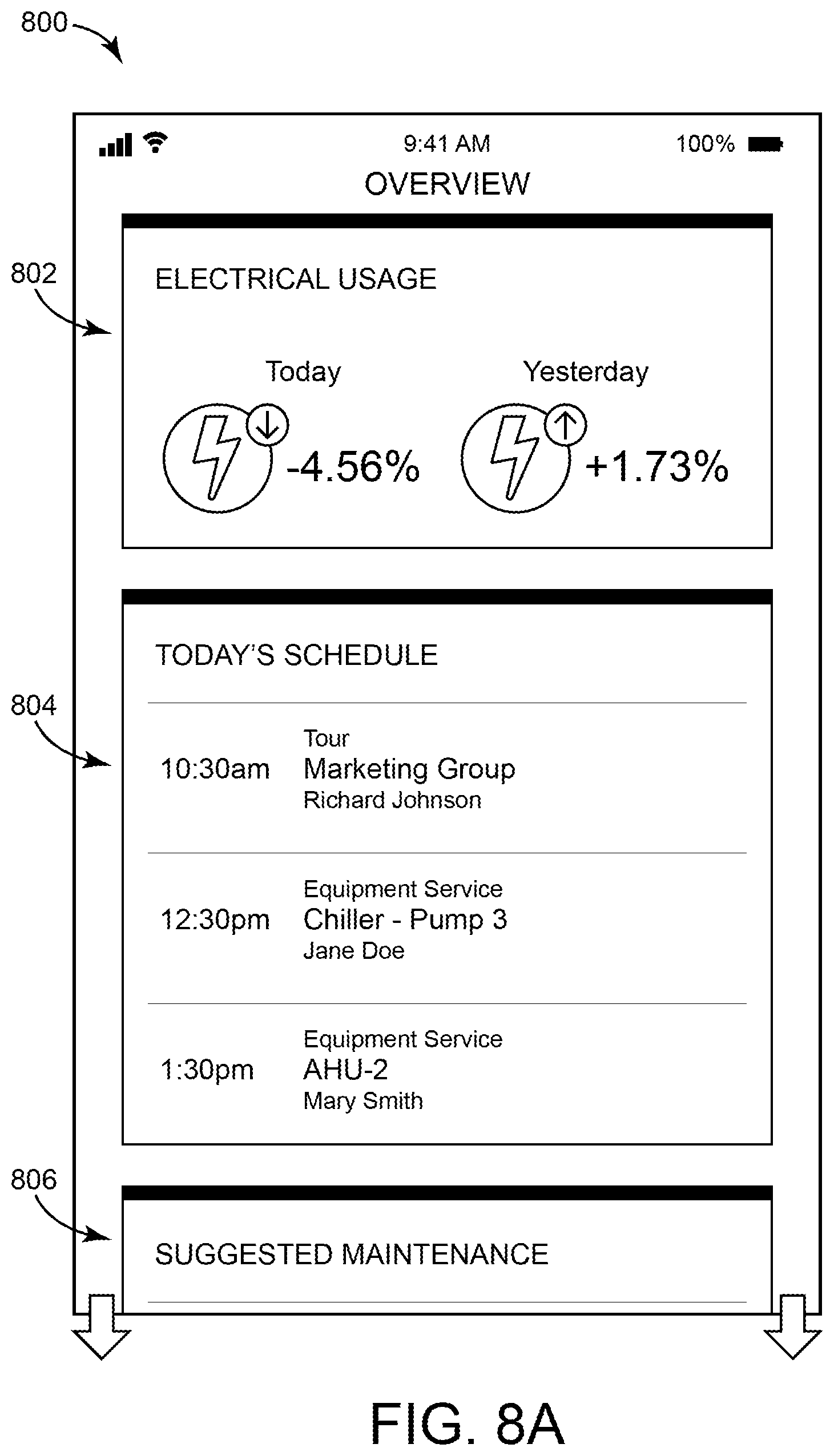
D00013
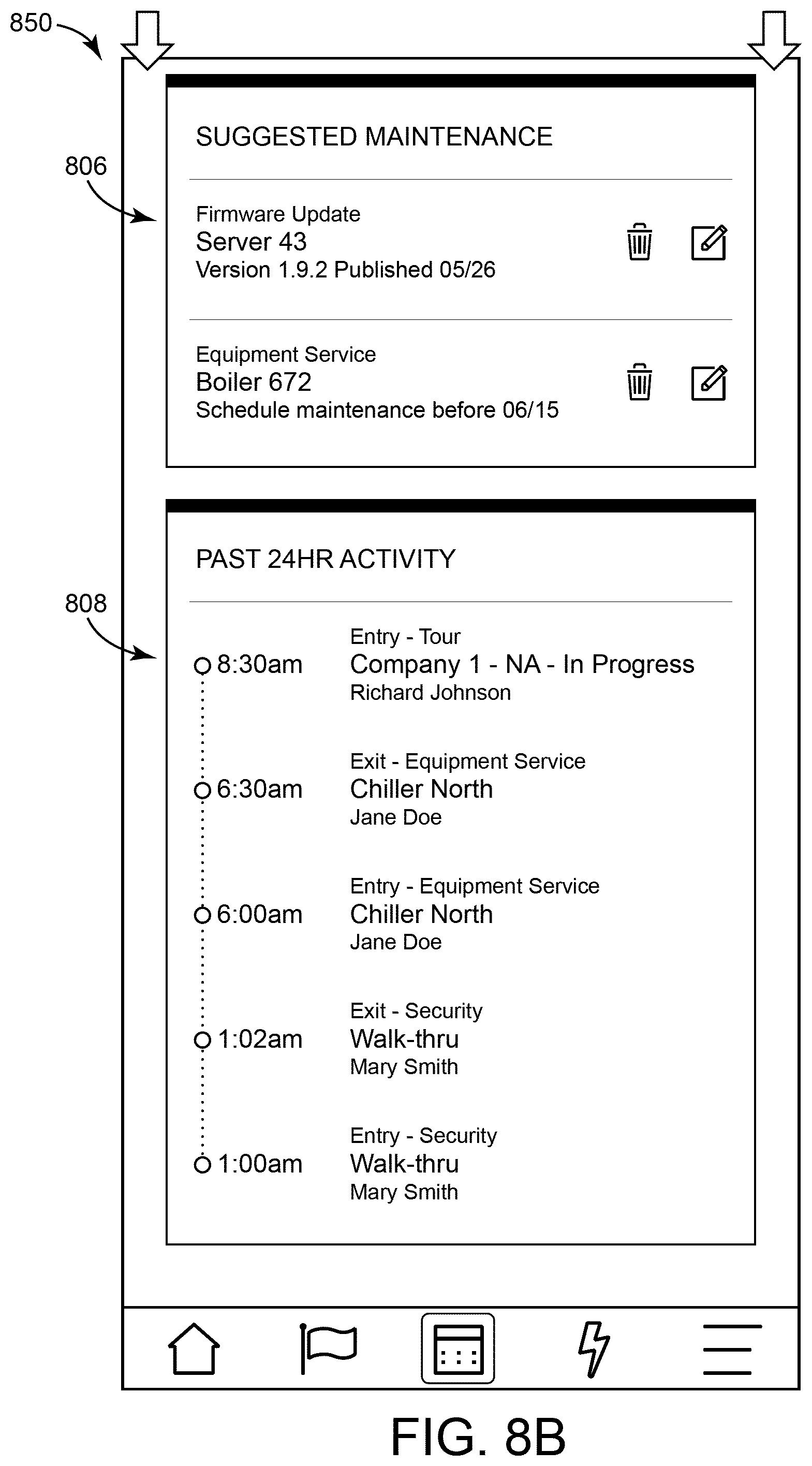
D00014

D00015
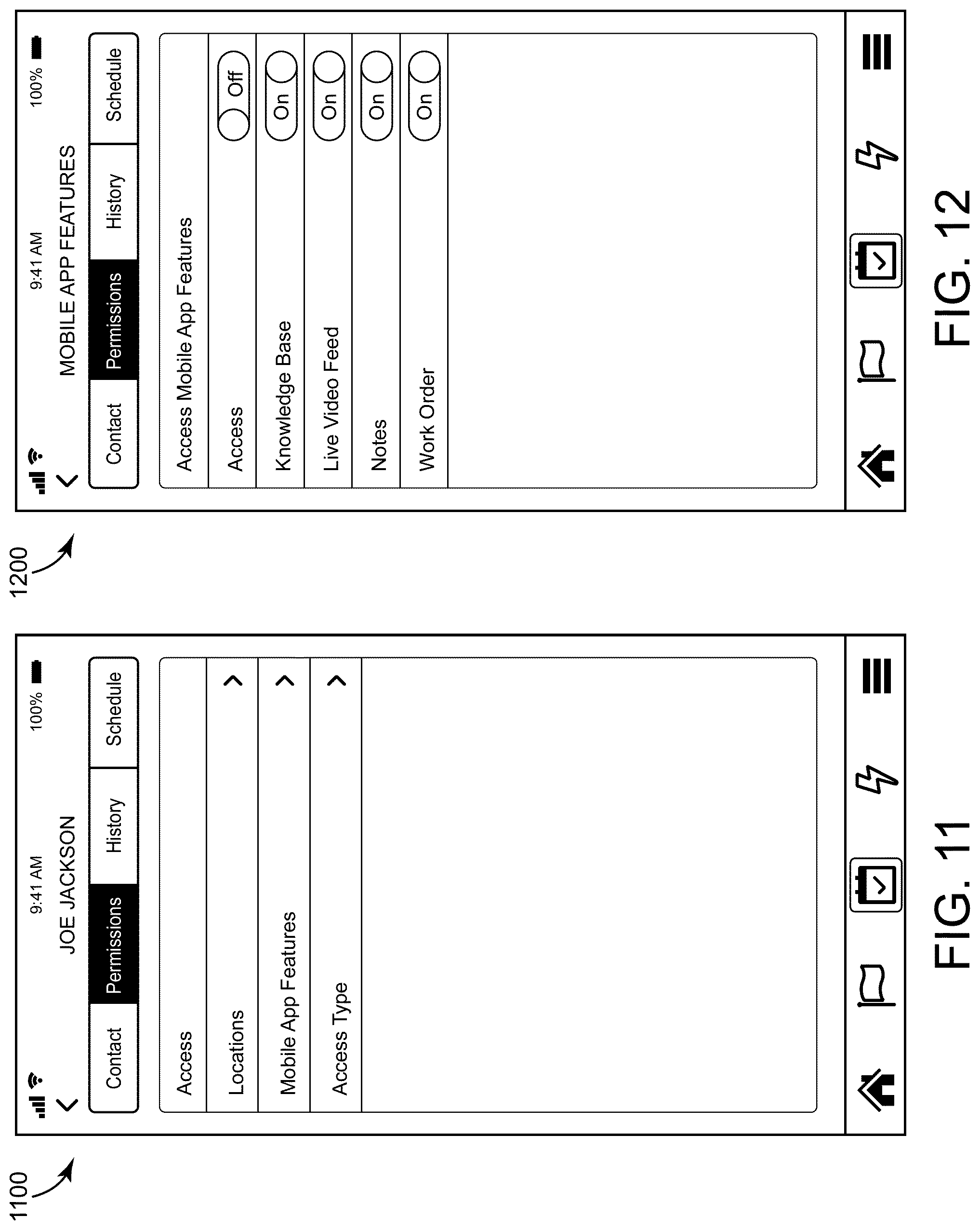
D00016
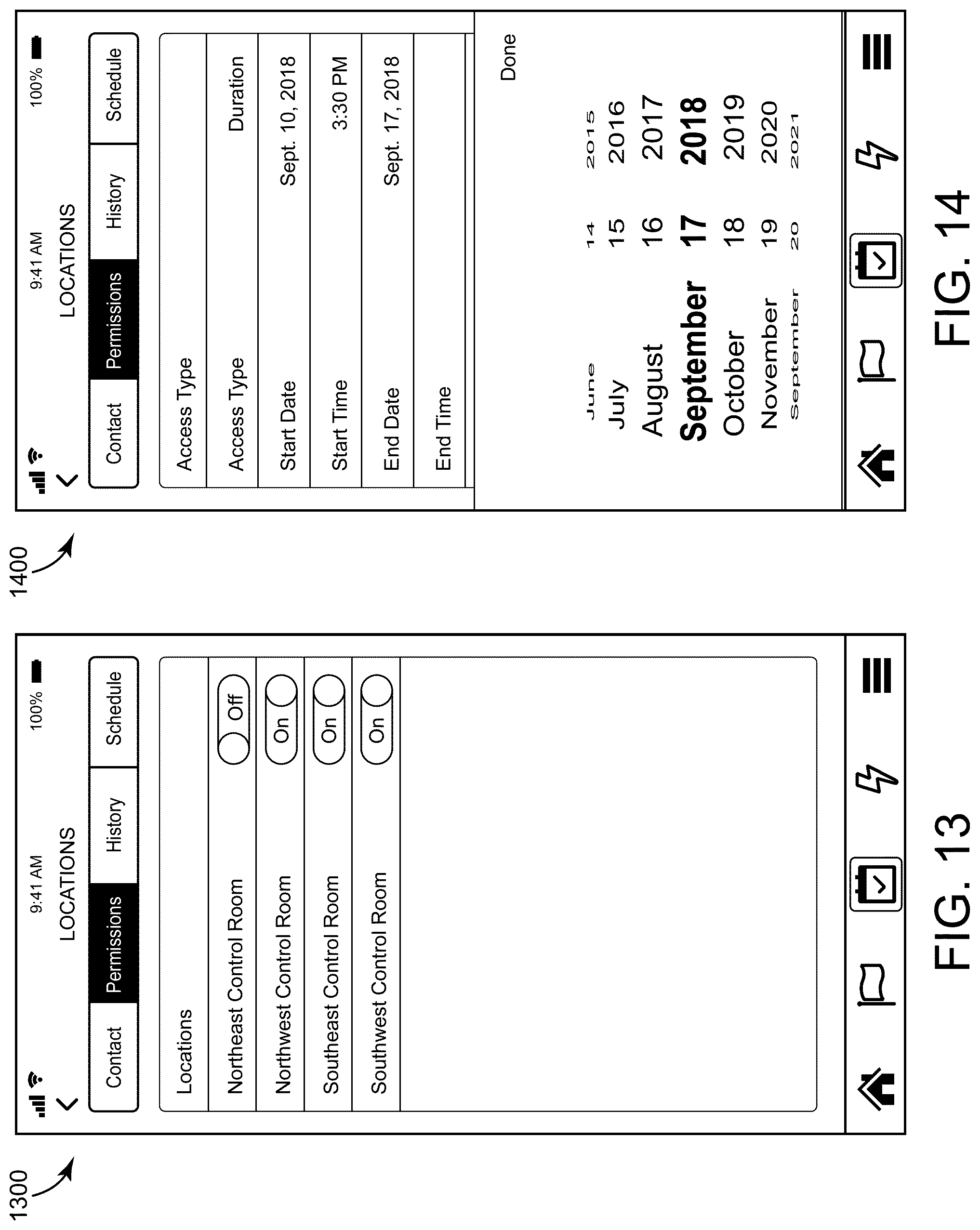
D00017
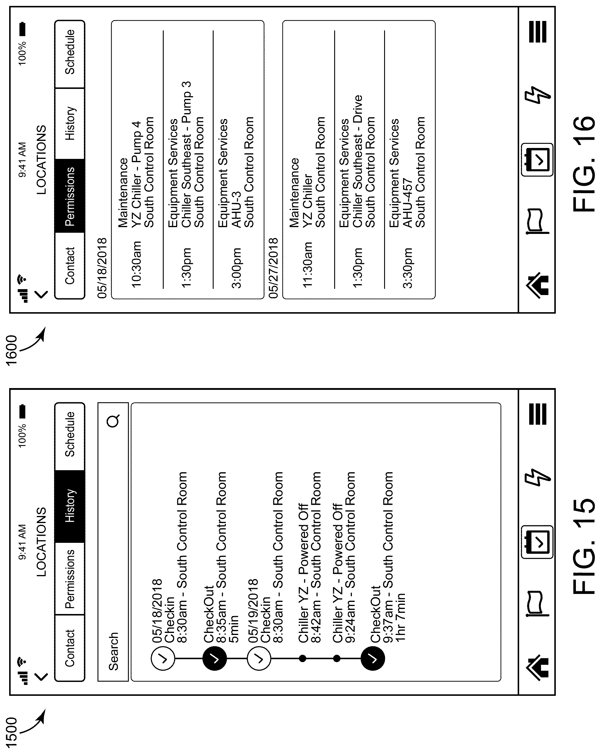
D00018

D00019

D00020
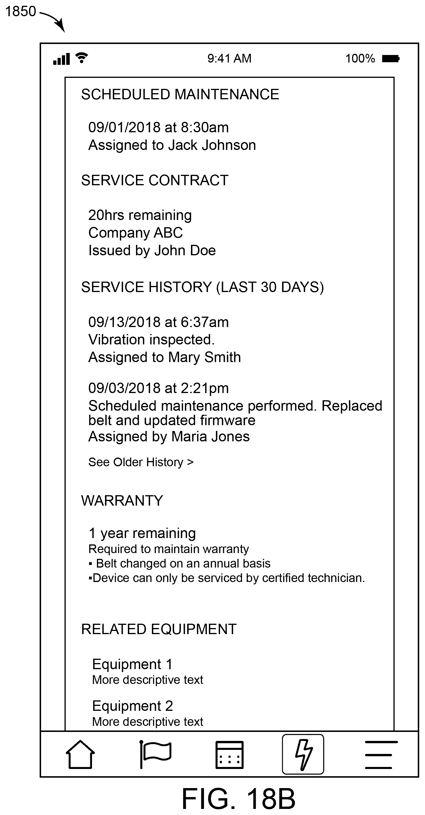
D00021
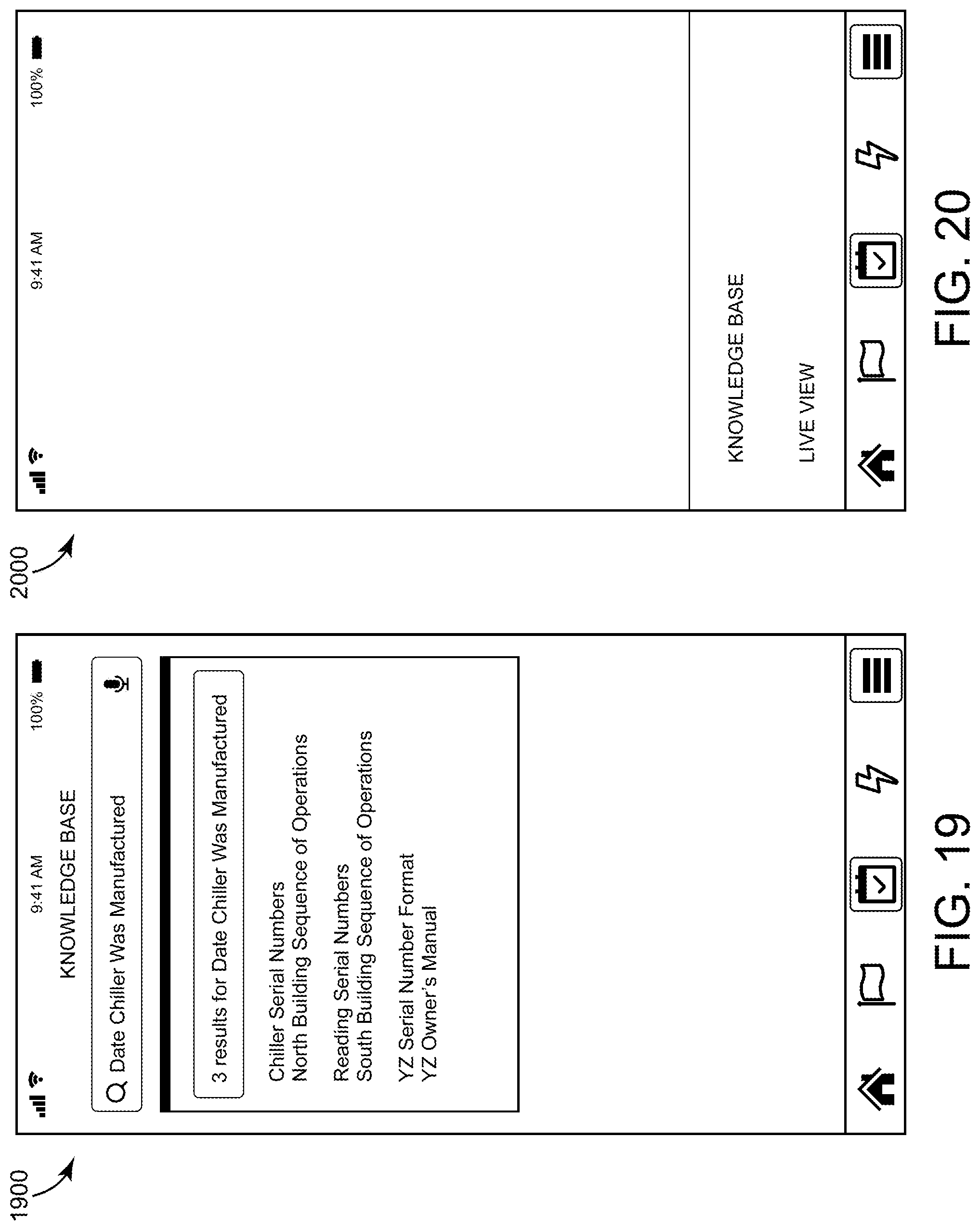
D00022

D00023

D00024
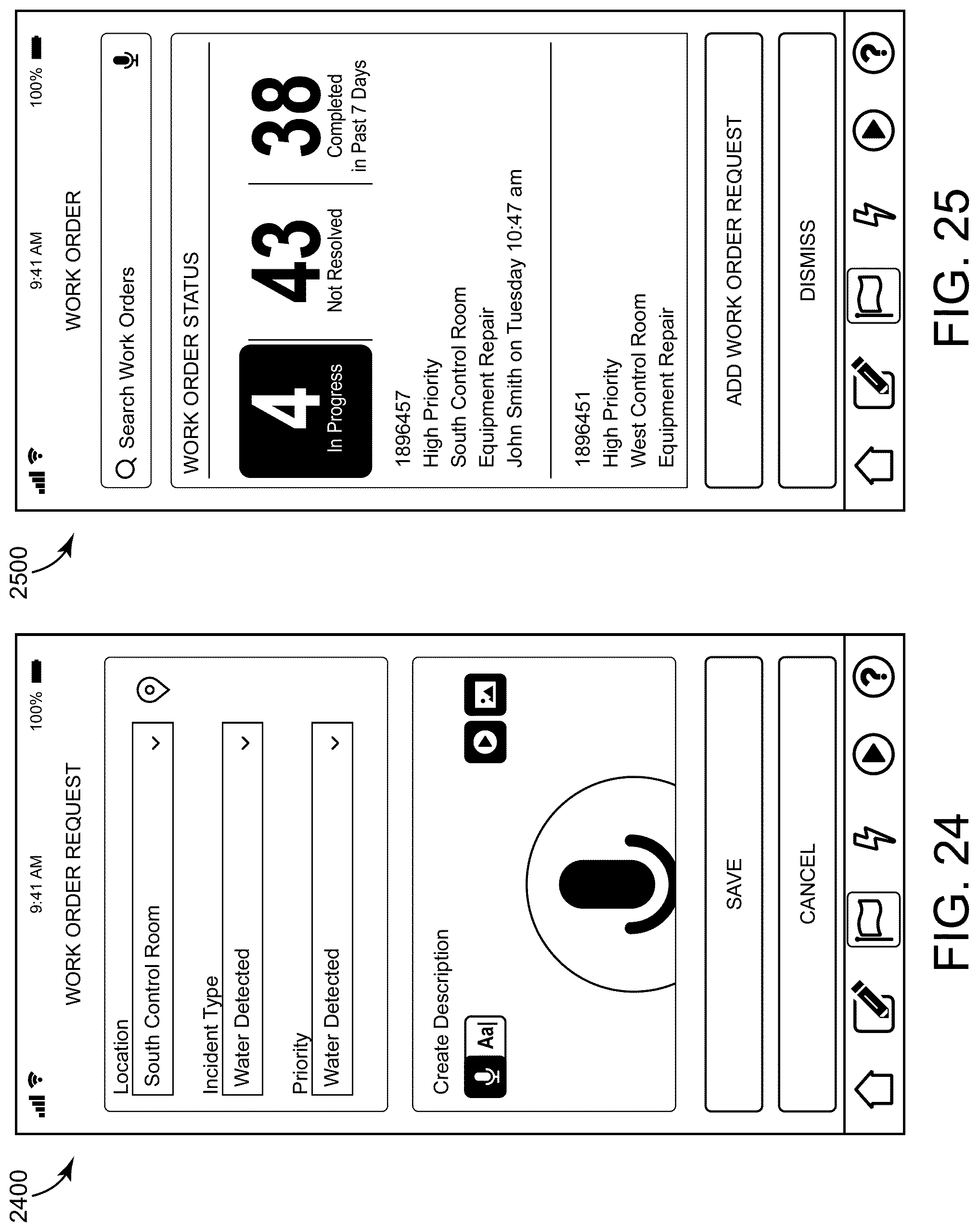
D00025

D00026
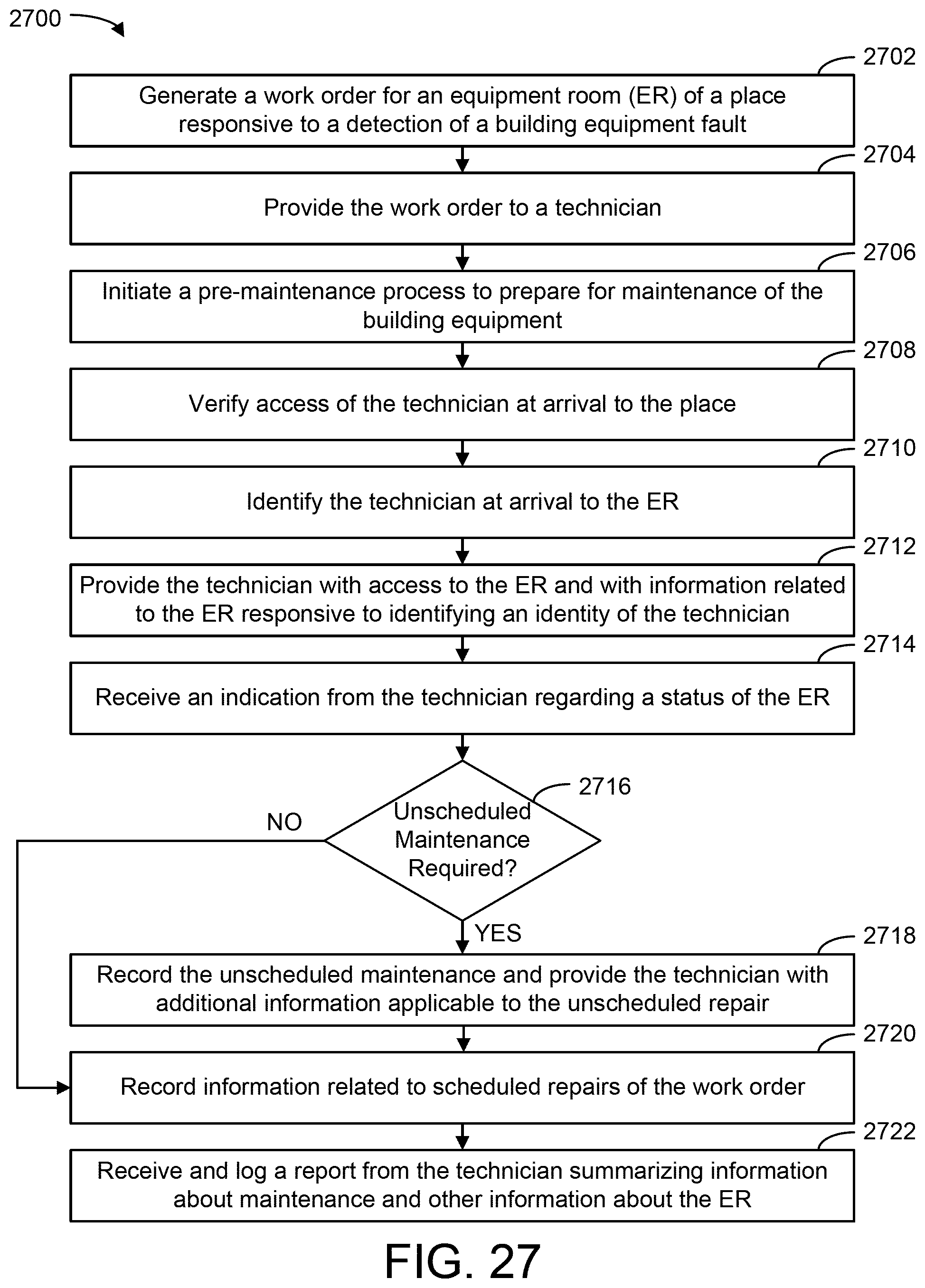
XML
uspto.report is an independent third-party trademark research tool that is not affiliated, endorsed, or sponsored by the United States Patent and Trademark Office (USPTO) or any other governmental organization. The information provided by uspto.report is based on publicly available data at the time of writing and is intended for informational purposes only.
While we strive to provide accurate and up-to-date information, we do not guarantee the accuracy, completeness, reliability, or suitability of the information displayed on this site. The use of this site is at your own risk. Any reliance you place on such information is therefore strictly at your own risk.
All official trademark data, including owner information, should be verified by visiting the official USPTO website at www.uspto.gov. This site is not intended to replace professional legal advice and should not be used as a substitute for consulting with a legal professional who is knowledgeable about trademark law.