Method For Thermally Insulating An Evacuable Container
GEISLER; Matthias ; et al.
U.S. patent application number 16/620481 was filed with the patent office on 2020-04-23 for method for thermally insulating an evacuable container. This patent application is currently assigned to EVONIK OPERATIONS GmbH. The applicant listed for this patent is EVONIK OPERATIONS GmbH STIEBEL ELTRON GmbH & Co. KG. Invention is credited to Hark-Oluf ASBAHR, Matthias GEISLER, Ann-Kathrin HERR, Dominik MEIER, Andreas MENG, Frank MENZEL, Dirk SCHAFFNER, Thorsten SCHULTZ.
| Application Number | 20200124231 16/620481 |
| Document ID | / |
| Family ID | 62492638 |
| Filed Date | 2020-04-23 |

| United States Patent Application | 20200124231 |
| Kind Code | A1 |
| GEISLER; Matthias ; et al. | April 23, 2020 |
METHOD FOR THERMALLY INSULATING AN EVACUABLE CONTAINER
Abstract
Method for thermal insulation of an evacuable container comprising an inner container, an outer container and a cavity disposed between the inner container and the outer container, wherein said method comprises a) using a vacuum pump to reduce a pressure in the cavity and after achieving a first value of the pressure interrupting the connection to the vacuum pump, b) subsequently making a connection from a reservoir container of the thermally insulating particulate material to a filling opening provided in the region of the cavity, c) setting the evacuable container into motion, wherein the thermally insulating particulate material flows into the cavity according to a) and the pressure in the cavity increases due to the air introduced with the thermally insulating particulate material, d) terminating the filling at a second value of the pressure by interrupting the connection from the cavity to the reservoir container, e) repeating step a), wherein the output of the vacuum pump with which the cavity is deaerated is controlled such that the profile over time of the mass flow exiting from the cavity of air introduced with the thermally insulating particulate material is at a maximum, f) subsequently repeating steps b)-e) up to the desired degree of filling and g) as the final step sealing the evacuated cavity.
| Inventors: | GEISLER; Matthias; (Norten-Hardenberg, DE) ; HERR; Ann-Kathrin; (Hanau, DE) ; ASBAHR; Hark-Oluf; (Gonnheim, DE) ; SCHULTZ; Thorsten; (Hassenroth, DE) ; SCHAFFNER; Dirk; (Hainburg, DE) ; MENZEL; Frank; (Hanau, DE) ; MENG; Andreas; (Hann. Munden, DE) ; MEIER; Dominik; (Holzminden, DE) | ||||||||||
| Applicant: |
|
||||||||||
|---|---|---|---|---|---|---|---|---|---|---|---|
| Assignee: | EVONIK OPERATIONS GmbH Essen DE STIEBEL ELTRON GmbH & Co. KG Holzminden DE |
||||||||||
| Family ID: | 62492638 | ||||||||||
| Appl. No.: | 16/620481 | ||||||||||
| Filed: | May 30, 2018 | ||||||||||
| PCT Filed: | May 30, 2018 | ||||||||||
| PCT NO: | PCT/EP2018/064248 | ||||||||||
| 371 Date: | December 6, 2019 |
| Current U.S. Class: | 1/1 |
| Current CPC Class: | F17C 2203/0337 20130101; F24D 2220/08 20130101; F17C 13/001 20130101; F17C 2203/0629 20130101; F17C 2203/0391 20130101; F28D 20/0034 20130101; F28F 2270/00 20130101; F17C 3/08 20130101; F17C 2203/0395 20130101 |
| International Class: | F17C 3/08 20060101 F17C003/08; F17C 13/00 20060101 F17C013/00 |
Foreign Application Data
| Date | Code | Application Number |
|---|---|---|
| Jun 9, 2017 | DE | 10 2017 209 782.5 |
Claims
1-9. (canceled)
10. A method for thermally insulating an evacuable container comprising an inner container, an outer container and a cavity disposed between the inner container and the outer container, wherein the cavity is provided to receive a thermally insulating particulate material; and wherein the method for providing the cavity with the thermally insulating particulate material comprises the steps of: evacuating the cavity; filling the cavity with the thermally insulating particulate material; compressing the thermally insulating particulate material in the cavity; evacuating the cavity; and sealing the cavity; wherein: a) a vacuum pump is used to reduce pressure in the cavity and after achieving a first value of the pressure, connection between the cavity and the vacuum pump is interrupted; b) subsequently making a connection from a reservoir container of the thermally insulating particulate material to a filling opening provided in the region of the cavity; c) setting the evacuable container into motion, wherein the thermally insulating particulate material flows into the cavity according to a) and the pressure in the cavity increases due to air introduced with the thermally insulating particulate material; d) terminating the filling at a second value of the pressure by interrupting the connection from the cavity to the reservoir container; e) repeating step a), wherein the output of the vacuum pump with which the cavity is deaerated is controlled such that the profile over time of the mass flow exiting from the cavity of air introduced with the thermally insulating particulate material is at a maximum; f) subsequently repeating steps b)-e) until desired degree of filling is reached; and g) as the final step sealing the evacuated cavity.
11. The method of claim 10 wherein the reservoir container is set into motion.
12. The method of claim 10, wherein the motion is a vibration or rotation.
13. The method of claim 10, wherein the thermally insulating particulate material is a compressed silica-comprising powder having a tamped density of 50-150 g/l.
14. The method of claim 13, wherein the silica is a hydrophobized silica.
15. The method of claim 13, wherein the silica is a hydrophilic silica.
16. The method of claim 13, wherein the silica comprises at least one hydrophilic and at least one hydrophobic silica.
17. The method of claim 13, wherein the compressed powder is a mixture of a silica and an IR opacifier.
18. The method of claim 17, wherein the proportion of the silica is 60-90% by weight and the proportion of the IR opacifier is 10-40% by weight.
19. The method of claim 12, wherein the thermally insulating particulate material is a compressed silica-comprising powder having a tamped density of 50-150 g/l.
20. The method of claim 19, wherein the silica is a hydrophobized silica.
21. The method of claim 19, wherein the silica is a hydrophilic silica.
22. The method of claim 19, wherein the silica comprises at least one hydrophilic and at least one hydrophobic silica.
23. The method of claim 19, wherein the compressed powder is a mixture of a silica and an IR opacifier.
24. The method of claim 23, wherein the proportion of the silica is 60-90% by weight and the proportion of the IR opacifier is 10-40% by weight.
25. The method of claim 23, wherein the silica is a hydrophobized silica.
26. The method of claim 23, wherein the silica is a hydrophilic silica.
27. The method of claim 26, wherein the silica comprises at least one hydrophilic and at least one hydrophobic silica.
28. The method of claim 27, wherein the proportion of the silica is 60-90% by weight and the proportion of the IR opacifier is 10-40% by weight.
Description
[0001] The invention relates to a method for thermal insulation of an evacuable container.
[0002] EP-A-645576 discloses a method for filling and compressing insulating powder into hollow walls of a boxlike body with subsequent evacuation of the gaseous medium so that the powder forms a vacuum insulation in the walls. The powder is pumped in at a first pressure and compressed at a second pressure.
[0003] DE-A-102010040346 discloses a method for manufacturing a thermally insulating shaped body which comprises the method steps of providing a mold, filling a pourable porous material, for example a granulate of an open-pored rigid plastics foam, an aerogel, a zeolite or a silica, into the mold, consolidating the pourable porous material in the mold and evacuating and sealing the mold.
[0004] DE-A-102013016705 discloses a method for insulating a hot water storage means. The hot water storage means comprises an inner container and an outer container, wherein between the inner container and the outer container a cavity for receiving an insulating layer made of an otherwise unspecified pourable fine-grained granulate is provided. The method contains the method steps: Filling the granulate into the cavity, compressing the granulate in the cavity, evacuating and sealing the cavity. The method may be implemented such that initially the granulate is filled into the cavity and compressed and subsequently the cavity is evacuated and sealed or initially the cavity is evacuated, subsequently the granulate is filled and compressed and finally the cavity is sealed.
[0005] The prior art also recites methods wherein a thermally insulating material is introduced into a cavity. The material may initially be introduced into the cavity with subsequent evacuation or else the cavity is initially evacuated and the thermally insulating material is introduced into the evacuated cavity. Both methods show disadvantages in execution. Disadvantages are for example in terms of filling duration, settling behaviour or discharging of previously introduced thermally insulating material.
[0006] It is accordingly an object of the present invention to provide a method having a short filling duration wherein discharging of thermally insulating material is minimized.
[0007] The invention provides a method for thermal insulation of an evacuable container, preferably a hot water container, comprising an inner container, an outer container and a cavity disposed between the inner container and the outer container, wherein the cavity is provided to receive a thermally insulating particulate material and for receiving the thermally insulating particulate material the steps of evacuating the cavity, filling the thermally insulating particulate material into the cavity, compressing the thermally insulating particulate material in the cavity, evacuating the cavity and sealing the cavity are performed,
[0008] wherein said method comprises [0009] a) using a vacuum pump to reduce a pressure in the cavity and after achieving a first value of the pressure interrupting the connection to the vacuum pump, [0010] b) subsequently making a connection from a reservoir container of the thermally insulating particulate material to a filling opening provided in the region of the cavity, [0011] c) setting the evacuable container into motion, wherein the thermally insulating particulate material flows into the cavity according to a) and the pressure in the cavity increases due to the air introduced with the thermally insulating particulate material, [0012] d) terminating the filling at a second value of the pressure by interrupting the connection from the cavity to the reservoir container, [0013] e) repeating step a), wherein the output of the vacuum pump with which the cavity is deaerated is controlled such that the profile over time of the mass flow exiting from the cavity of air introduced with the thermally insulating particulate material is at a maximum, [0014] f) subsequently repeating steps b)-e) up to the desired degree of filling and [0015] g) as the final step sealing the evacuated cavity.
[0016] It may be advantageous to likewise set the reservoir container into motion. This motion may be a vibration or rotation both for the evacuable container and for the reservoir container. Stirring, tilting, pressurizing with gas or fluidizing by other means could also be carried out in the reservoir container.
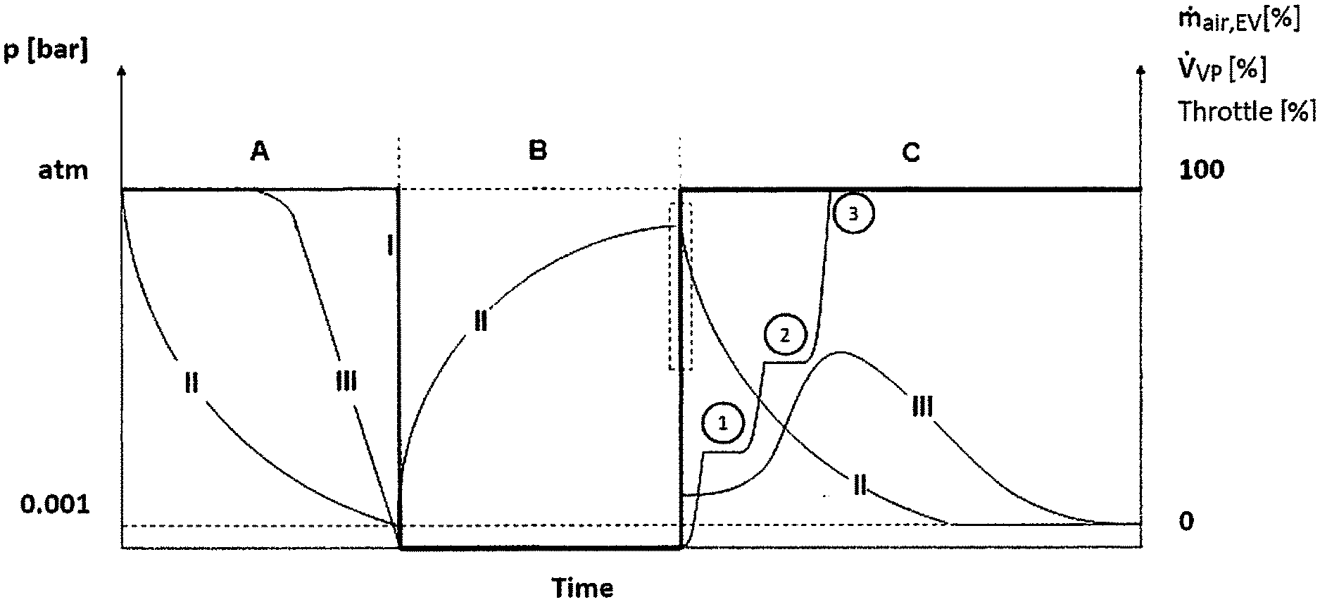
[0017] FIG. 1 is a schematic diagram of the method according to the invention when using a throttle valve in the evacuation procedure before sealing the cavity in section C of the figure. In the figure: [atm]=atmospheric pressure; {dot over (V)}.sub.VP [%]=aspirated volume flow; {dot over (m)}.sub.air, EV [%]=air mass flow; throttle [%]=throttle valve opening.
[0018] Section A shows the pressure (II) in the cavity during evacuation of the cavity not yet filled with the thermally insulating particulate material from atmospheric pressure (atm) to less than 100 mbar, in particular to less than 20 mbar, in particular to less than 5 mbar. A high mass flow of air (III) is initially present and said mass flow falls with falling pressure (II) in each case depending on the volume of the cavity and the aspirated volume flow {dot over (v)}.sub.VP (I) of the vacuum pump.
[0019] Section B shows the filling of the cavity with the thermally insulatin. particulate material.
[0020] To this end a connection between the reservoir container and the cavity is opened, thus effecting a pressure equalization. A slight negative pressure is generally established in the cavity. The negative pressure depends inter alia on the geometry of the containers, their arrangement with respect to one another and the thermally insulating particulate material. The magnitude of the negative pressure (dashed rectangle) is not determined and is not relevant for performing the method according to the invention.
[0021] The mass flow of the outflowing air is zero.
[0022] Section C shows the evacuation of the filled annular slot. The evacuation is divided into three sections for example.
[0023] Section 1: Evacuation procedure in progress, valve position of throttle increases to 25%. A small mass flow of air is observed.
[0024] Section 2: Evacuation procedure in progress, valve position of throttle increases to 50%. A markedly increasing mass flow of air is observed.
[0025] Section 3: Evacuation procedure in progress, valve position of throttle increases to 100%. It is observed that the mass flow of air increases further and reaches a maximum. Evacuation procedure remains in progress until target pressure, for example less than 100 mbar, in particular less than 20 mbar, in particular less than 5 mbar, is achieved. It is observed that the mass flow of air reduces.
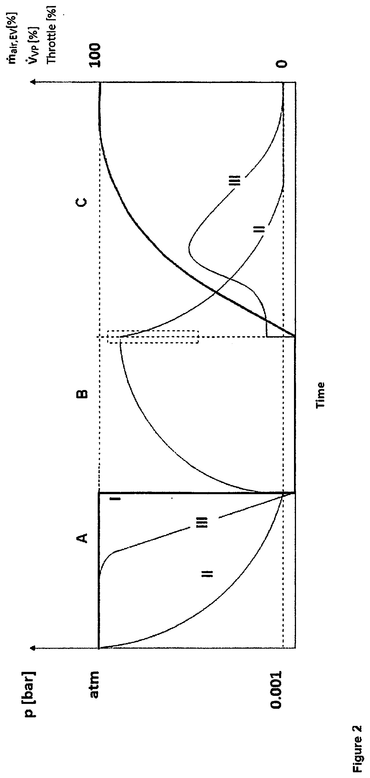
[0026] FIG. 2 is a schematic diagram of the method according to the invention when using a controllable vacuum pump in the evacuation procedure before sealing the cavity in section C of the figure.
[0027] In the figure: [atm]=atmospheric pressure; {dot over (V)}.sub.VP [%]=aspirated volume flow; {dot over (m)}.sub.air, EV [%]=air mass flow.
[0028] The comments made in respect of FIG. 1 apply for sections A and B.
[0029] Section C shows the evacuation of the filled annular slot. As the pressure stage decreases, the aspirated volume flow {dot over (V)}.sub.VP of the vacuum pump is increased. Mass flow initially increases but then decreases since the proportion of air in the cavity decreases.
[0030] A controlled mass flow of air is important for the filling procedure. Said mass flow is thus limited for example to a predetermined low value at commencement of the evacuation, in particular via an output limiting means of the vacuum pump or a throttle valve so that no thermally insulating particulate material is entrained. In a second step when a particular value of the vacuum has already been achieved, the pump output is increased or the throttling is reduced further. This need not necessarily be associated with a mass flow increase of the air since as the vacuum decreases the pump output must increase in order that air may still be aspirated from the cavity against the vacuum.
[0031] According to an advantageous concept of the invention, the commencement of the evacuation is commenced with a starting volume flow of air. In the course of the evacuation, the volume flow of air, starting from the starting volume flow, is advantageously further increased, in particular the volume flow of air is increased by approximately 2 to 5 times the starting volume flow or else up to 10 or 20 times the starting volume flow. The mass flow of air advantageously reduces.
[0032] The thermally insulating particulate material employed in the method according to the invention is preferably a compressed silica-comprising powder having a tamped density of 50-150 g/l. The tamped density may be determined according to ISO 697/EN ISO 60; DIN 53468.
[0033] Such a material has a low thermal conductivity, good flow properties during filling, while discharge during evacuation of the cavity is minimal or entirely negligible. The compressed powder preferably has a thermal conductivity of less than 5 mW/mK at a pressure of 100 hPa or less than 25 mW/mK at a pressure of 1000 hPa. The compressed powder is distinct from a granulate in respect of its tamped density and its flow behaviour.
[0034] The silica is preferably a pyrogenic silica. Pyrogenically produced silicas are preferably employed. Pyrogenic silicas are generally in aggregated form or at least partly aggregated. "Aggregated" is to be understood as meaning that so-called primary particles formed initially during generation make strong interconnections in the further course of the reaction to form a three-dimensional network. The description "at least partly aggregated" is intended to elucidate that in addition to aggregates isolated individual particles may also be present, wherein at least 80% of the hydrophobized silicon dioxide particles should be present in the form of aggregates. Such a silica shows good values in respect of both thermal insulation and mechanical stability of the three-dimensional network. The ratio of aggregate to isolated individual particles may be determined for example by quantitative evaluation of TEM micrographs (TEM=transmission electron microscopy). The silicon dioxide particles are amorphous.
[0035] The term "pyrogenically" encompasses production of silica by means of flame hydrolysis and flame oxidation. Here, oxidizable and/or hydrolysable starting materials are oxidized or hydrolysed generally in a hydrogen/oxygen flame. Starting materials that may be used for pyrogenic methods include organic and inorganic substances. Silicon tetrachloride is particularly suitable. The thus obtained hydrophilic silica is very largely pore-free and has free hydroxyl groups on its surface. The BET surface area of pyrogenic silica is generally 30 to 500 m.sup.2/g. For the method according to the invention, in particular a BET surface area of at least 150 m.sup.2/g is preferred.
[0036] The silica used in the method according to the invention may comprise a hydrophilic silica, a hydrophobized silica or at least one hydrophilic and at least one hydrophobic silica.
[0037] It has proven particularly useful to employ a hydrophobized silica. These are obtained from the reaction of hydrophilic silicas with a hydrophobizing agent. The hydroxyl groups present at the surface of the hydrophilic silica are partly or completely converted. The degree of hydrophobization may be determined by the methanol wettability.
[0038] Thus, the silica should have a methanol wettability of at least 20 vol % of methanol, preferably 20-80 vol % of methanol. Hydrophobic silicas may be rendered water-wettable by addition of methanol. This is effected by methanol/water mixtures of different concentrations. This makes it possible to reveal the degree of hydrophobization of the silicas.
[0039] The hydrophobized silica may preferably be obtained by reaction of a hydrophilic silica with an organosilane from the group consisting of R.sub.n--Si--X.sub.4-n, R.sub.3Si--Y--SiR.sub.3, R.sub.nSi.sub.nO.sub.n, (CH.sub.3).sub.3--Si--(O--Si(CH.sub.3).sub.2).sub.n--OH, HO--Si(CH.sub.3).sub.2--(O--Si(CH.sub.3).sub.2).sub.n--OH, where n=1-8; R=--H, --CH.sub.3, --C.sub.2H.sub.5; X=--Cl, --Br; --OCH.sub.3, --OC.sub.2H.sub.5, --OC.sub.3H.sub.8, Y.dbd.NH, O.
[0040] The hydrophobic properties thereof ensure that only very small amounts, if any, of adhering water are introduced into the cavity to be filled. Adhering water can result in an undesired reduction of the vacuum and thus in an increased thermal conductivity. It may therefore be advantageous to introduce the thermally insulating particulate material in a very largely water-free state. While this may be achieved by drying methods or a subsequent reduction in pressure, this can slow the filling procedure.
[0041] The compressed powder is preferably employed as a mixture of a silica and an IR opacifier. A proportion of 60-90% by weight of a silica and 10-40% by weight of an IR opacifier is particularly preferred. Suitable IR opacifiers are titanium oxides, zirconium oxides, ilmenites, iron titanates, iron oxides, zirconium silicates, silicon carbide, manganese oxides, graphites and/or carbon blacks. The particle size of the opacifiers is generally between 0.1 and 25 .mu.m. In the case of silicon carbide and titanium oxides, the average particle diameter d50 is preferably 1 to 10 .mu.m, particularly preferably 2 to 8 .mu.m.
* * * * *
D00000
D00001
D00002
XML
uspto.report is an independent third-party trademark research tool that is not affiliated, endorsed, or sponsored by the United States Patent and Trademark Office (USPTO) or any other governmental organization. The information provided by uspto.report is based on publicly available data at the time of writing and is intended for informational purposes only.
While we strive to provide accurate and up-to-date information, we do not guarantee the accuracy, completeness, reliability, or suitability of the information displayed on this site. The use of this site is at your own risk. Any reliance you place on such information is therefore strictly at your own risk.
All official trademark data, including owner information, should be verified by visiting the official USPTO website at www.uspto.gov. This site is not intended to replace professional legal advice and should not be used as a substitute for consulting with a legal professional who is knowledgeable about trademark law.