Curvilinear circular-arc tooth gears for use in external gear pumps
Williams; Logan
U.S. patent application number 16/587144 was filed with the patent office on 2020-04-23 for curvilinear circular-arc tooth gears for use in external gear pumps. The applicant listed for this patent is The Government of the United States of America, as represented by the Secretary of the Navy. Invention is credited to Logan Williams.
| Application Number | 20200124047 16/587144 |
| Document ID | / |
| Family ID | 70280596 |
| Filed Date | 2020-04-23 |


View All Diagrams
| United States Patent Application | 20200124047 |
| Kind Code | A1 |
| Williams; Logan | April 23, 2020 |
Curvilinear circular-arc tooth gears for use in external gear pumps
Abstract
A curvilinear circular-arc-toothed (CCAT) gear for improving gear performance and reducing noise while avoiding axial loads common to helical gears includes an annular gear body; and a gear tooth having a hybrid gear tooth profile comprising one or more curves configured to provide a sweep of the gear tooth space by a mating gear tooth while maintaining smooth contact during gear mesh, and wherein the gear tooth extends along an axial length of the gear body along an axial profile.
| Inventors: | Williams; Logan; (Alexandria, VA) | ||||||||||
| Applicant: |
|
||||||||||
|---|---|---|---|---|---|---|---|---|---|---|---|
| Family ID: | 70280596 | ||||||||||
| Appl. No.: | 16/587144 | ||||||||||
| Filed: | September 30, 2019 |
Related U.S. Patent Documents
| Application Number | Filing Date | Patent Number | ||
|---|---|---|---|---|
| 62749498 | Oct 23, 2018 | |||
| Current U.S. Class: | 1/1 |
| Current CPC Class: | F04C 2230/10 20130101; F04C 2/084 20130101; F04C 2/18 20130101; F04C 15/0042 20130101 |
| International Class: | F04C 15/00 20060101 F04C015/00; F04C 2/08 20060101 F04C002/08 |
Goverment Interests
FEDERALLY-SPONSORED RESEARCH AND DEVELOPMENT
[0002] The United States Government has ownership rights in this invention. Licensing inquiries may be directed to Office of Technology Transfer, US Naval Research Laboratory, Code 1004, Washington, D.C. 20375, USA; +1.202.767.7230; techtran@nrl.navy.mil, referencing NC 107458.
Claims
1. A curvilinear circular-arc-toothed (CCAT) gear for improving gear performance and reducing noise while avoiding axial loads common to helical gears, the CCAT gear comprising: an annular gear body; and a set of gear teeth, with each tooth extending radially away from the gear body and extending axially along the gear body, and wherein the gear tooth has a cross-sectional profile transverse to the rotational axis of the gear body, the cross-sectional profile formed from a hybridization of two or more curves, the two or more curves defining a tooth tip, a tooth flank, and a tooth root, and wherein the gear tooth has an axial tooth profile defining a circumferential positioning of the gear tooth on the gear body relative to a respective axial positioning of the gear tooth on the gear body, the axial tooth profile being generally symmetric across the midplane of the gear to reduce axial loading on gears induced by gear meshing.
2. The CCAT gear of claim 1, wherein the axial tooth profile is continuously differentiable.
3. The CCAT gear of claim 1, wherein the axial tooth profile is fully symmetric about an axial mid-plane of the gear to eliminate axial loading from gear meshing.
4. The CCAT gear of claim 1, wherein the axial tooth profile has an initial helix angle at each end of the gear.
5. The CCAT gear of claim 1, wherein the axial tooth profile is curvilinear.
6. The CCAT gear of claim 5, wherein the axial tooth profile is a half-period sinusoid function.
7. The CCAT gear of claim 1, wherein the gear tooth cross-sectional profile is configured such that the tip fully sweeps along a tooth root of a mating gear.
8. The CCAT gear of claim 7, wherein the tooth tip and root profiles include a circular-arc.
9. The CCAT gear of claim 1, wherein the tooth flank is a curve that allows smooth meshing of the gears.
10. The CCAT gear of claim 9, wherein the tooth flank is involute, cycloidal, or circular arc.
11. The CCAT gear of claim 9, wherein the tooth flank is an involute curve.
12. The CCAT gear of claim 1, wherein the tooth tip is circular, the tooth flank is involute, and the tooth root is circular.
13. The CCAT gear of claim 1, wherein the two or more curves of the hybrid tooth profile are combined such that the cross-sectional profile of the tooth is continuously differentiable.
14. The CCAT gear of claim 1, wherein the gear teeth extend radially outward from the annular body.
15. A curvilinear circular-arc-toothed (CCAT) gear for improving gear performance and reducing noise while reducing axial loads common to helical gears, the CCAT gear comprising: an annular gear body; and a gear tooth having a hybrid gear tooth profile comprising one or more curves configured to provide a sweep of the gear tooth space by a mating gear tooth while maintaining smooth contact during gear mesh, and wherein the gear tooth extends along an axial length of the gear body along an axial profile.
16. The CCAT gear of claim 15, wherein the hybrid gear tooth profile has a tip that conforms to a tooth root of the mating gear to allow fully sweeping out the volume between gear teeth to improve efficiency and reduce noise.
17. The CCAT gear of claim 16, wherein the hybrid gear tooth profile has a circular arc at a tooth tip, a circular arc at a tooth root, and the profile combines the two arcs with an involute curve between the circular arcs to allow a full sweep of the volume between gear teeth while maintaining a constant line of action of the mesh.
18. The CCAT gear of claim 15, wherein a radius of a tooth tip arc is equal to or less than a radius of a tooth root arc.
19. The CCAT gear of claim 15, wherein the hybrid profile is continuously differentiable.
20. The CCAT gear of claim 15, wherein the axial profile is configured to cause gradual contact between teeth to reduce shock stress on the gear teeth and noise during meshing.
21. The CCAT gear of claim 15, wherein the axial profile is configured to balance axial forces imparted on the gears from meshing to reduce net axial load on the gear.
Description
RELATED APPLICATIONS
[0001] This application claims the benefit of U.S. Provisional Application No. 62/749,498 filed Oct. 23, 2018, which is hereby incorporated herein by reference.
FIELD OF INVENTION
[0003] The present invention relates generally to gears, and more particularly to gears used in gear pumps.
BACKGROUND
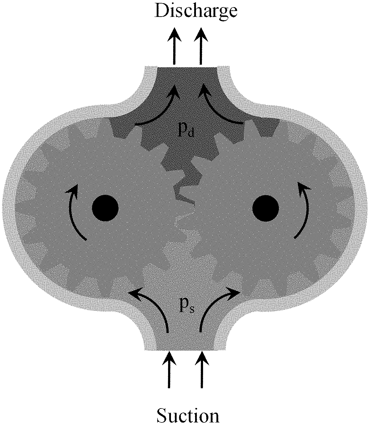
[0004] The basic function of an external gear pump as shown in FIG. 1, is to drive the flow of a fluid through the rotary action of two meshed gears. At one side of the meshing zone (termed the suction side), the gear teeth unmesh, creating a void that draws fluid into the tooth spaces of the gears. These fluid packets are then rotated around the gear into the discharge region; at this side the teeth mesh together, driving the fluid out of the inter-tooth spaces. This pushes the fluid out the discharge of the pump through whatever hydraulic load is connected to the pump. As a fixed-displacement pump, a gear pump will pressurize the fluid to whatever pressure is required to drive the flow rate created by the meshing gears (a mechanical analog to a current-limited power supply).
[0005] It is important to note that there are two main fluid pathways: the intentional hydraulic load (i.e. a piston, actuator, motor, etc.) and an internal leakage path where pressurized fluid in the discharge leaks across the gears back into the suction side of the pump. The internal leakage flow rate is dependent on the size of the clearances between components, as well as the discharge pressure (the higher the pressure, the more fluid that can be forced through an opening). Thus, one of the limitations to the maximum discharge pressure of a pump is the internal sealing to prevent appreciable leakage. This results in gear pump designs where there is minimal radial clearance between the tips of the gear teeth and the pump casing. Additionally, the axial surfaces of the gears are sealed with two wear plates that conform to the pumping cavity shape. These wear plates ensure a tight seal and minimize leakage, but can also contribute to frictional losses during operation.
[0006] The most common gear tooth profile used in gear pumps is an involute profile. The primary advantages of the involute profile is that it provides smooth, consistent contact between two gears during meshing, and that it is relatively cost-effective to machine involute gears using basic cutting and hobbing techniques.
SUMMARY OF INVENTION
[0007] The key disadvantage of an involute profile is that during the meshing action, the addendum of one tooth does not fully sweep the dedendum of the corresponding tooth of the mating gear. This results in a pocket of fluid being trapped between the teeth during meshing. As the meshing action progresses, the fluid pocket pressure rises significantly, contributing to noise and gear wear.
[0008] According to one aspect of the invention, a curvilinear circular-arc-toothed (CCAT) gear for improving gear performance and reducing noise while avoiding axial loads common to helical gears includes: an annular gear body; and a set of gear teeth, with each tooth extending radially away from the gear body and extending axially along the gear body. The gear tooth has a cross-sectional profile transverse to the rotational axis of the gear body, the cross-sectional profile formed from a hybridization of two or more curves, the two or more curves defining a tooth tip, a tooth flank, and a tooth root. The gear tooth has an axial tooth profile defining a circumferential positioning of the gear tooth on the gear body relative to a respective axial positioning of the gear tooth on the gear body, the axial tooth profile being symmetric across the midplane of the gear to reduce axial loading on gears induced by gear meshing.
[0009] Optionally, the axial tooth profile is continuously differentiable
[0010] Optionally, the axial tooth profile has an initial helix angle at each end of the gear.
[0011] Optionally, the axial tooth profile is curvilinear.
[0012] Optionally, the axial tooth profile is a half-period sinusoid function.
[0013] Optionally, the gear tooth cross-sectional profile is configured such that the tip of one gear fully sweeps along the tooth root of the mating gear.
[0014] Optionally, the tooth tip and root profiles include a circular-arc.
[0015] Optionally, the tooth flank is a curve that allows smooth meshing of the gears.
[0016] Optionally, the tooth flank is involute, cycloidal, or circular arc.
[0017] Optionally, the tooth flank is an involute curve.
[0018] Optionally, the tooth tip is circular, the tooth flank is involute, and the tooth root is circular.
[0019] Optionally, the two or more curves of the hybrid tooth profile are combined such that the cross-sectional profile of the tooth is continuously differentiable.
[0020] Optionally, the gear teeth extend radially outward from the annular gear body.
[0021] According to another aspect of the invention, a curvilinear circular-arc-toothed (CCAT) gear for improving gear performance and reducing noise while reducing axial loads common to helical gears includes: an annular gear body; and a gear tooth having a hybrid gear tooth profile comprising one or more curves configured to provide a sweep of the gear tooth space by a mating gear tooth while maintaining smooth contact during gear mesh, and wherein the gear tooth extends along an axial length of the gear body along an axial profile.
[0022] Optionally, the hybrid gear tooth profile has a tip that conforms to a tooth root of the mating gear to allow fully sweeping out the volume between gear teeth to improve efficiency and reduce noise.
[0023] Optionally, the hybrid gear tooth profile has a circular arc at a tooth tip, a circular arc at a tooth root, and the profile combines the two arcs with an involute curve between the circular arcs to allow a full sweep of the volume between gear teeth while maintaining a constant line of action of the mesh.
[0024] Optionally, a radius of a tooth tip arc is equal to or less than a radius of a tooth root arc.
[0025] Optionally, the hybrid profile is continuously differentiable.
[0026] Optionally, the axial profile is configured to cause gradual contact between teeth to reduce shock stress on the gear teeth and noise during meshing.
[0027] Optionally, the axial profile is configured to balance axial forces imparted on the gears from meshing to reduce net axial load on the gear.
[0028] The foregoing and other features of the invention are hereinafter described in greater detail with reference to the accompanying drawings.
BRIEF DESCRIPTION OF THE DRAWINGS
[0029] FIG. 1 schematically shows the function of conventional and exemplary gear pumps.
[0030] FIG. 2 shows exemplary geometry of one half of a tooth profile. Curve end points are identified A through D. Top and bottom lines (A-B and C-D) denote circular curves, while the curved line between(B-C) denote the involute curve. Pitch, base, and root circles are denoted by the dot-dash lines and labeled as r.sub.p, r.sub.b, and r.sub.r respectively.
[0031] FIG. 3 shows the origin of an exemplary involute curve y.sub.f(x). The dashed line between points C and C.sub.0 denotes the part of the involute curve that is not used in the actual tooth profile.
[0032] FIG. 4 shows an exemplary post-splice tooth profile.
[0033] FIG. 5 shows a simplified block diagram of an exemplary process for building a CAD model of an exemplary gear.
[0034] FIG. 6 shows a graphical depiction of the process of FIG. 5.
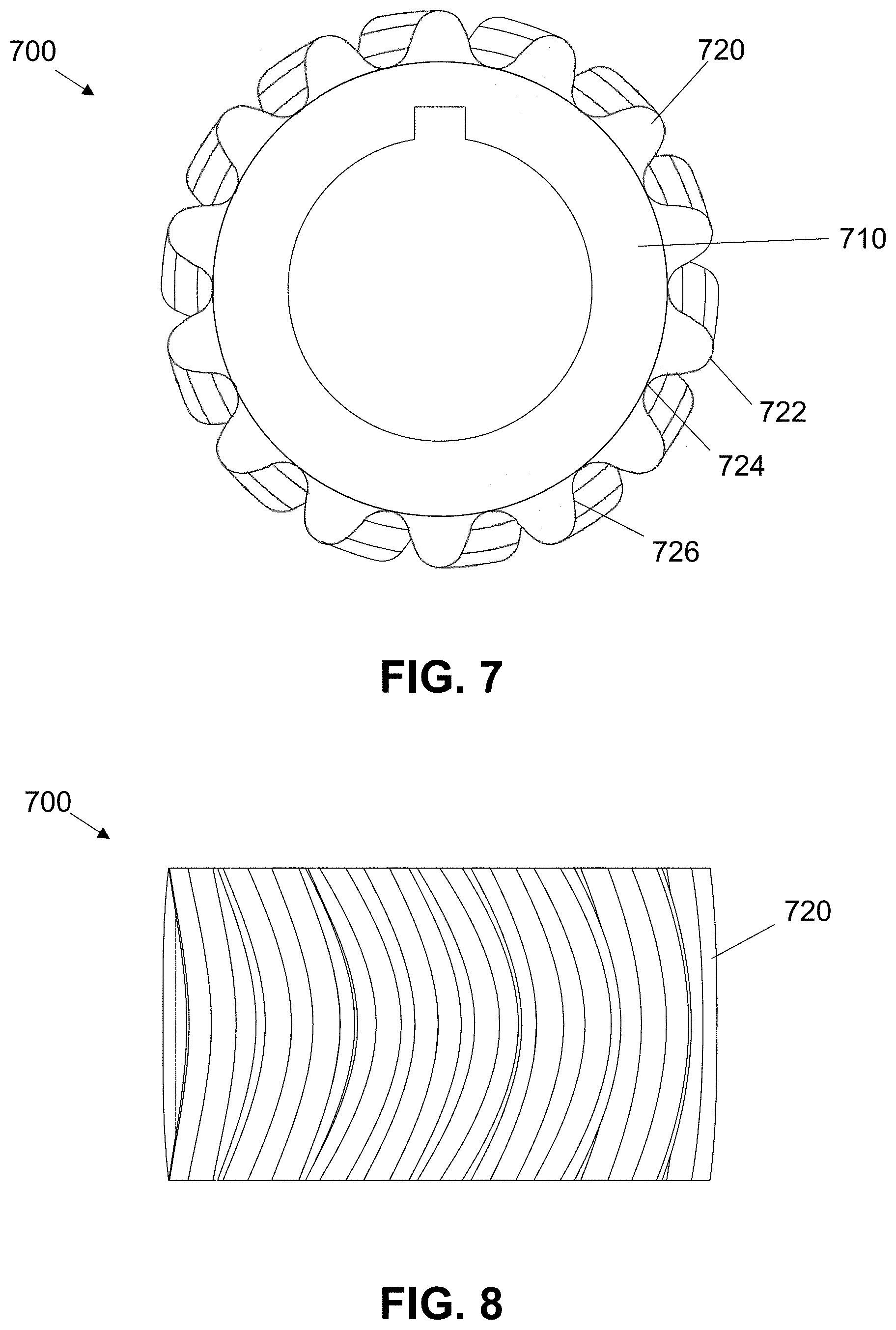
[0035] FIG. 7 shows a top view of an exemplary gear.
[0036] FIG. 8 shows a side view of an exemplary gear.
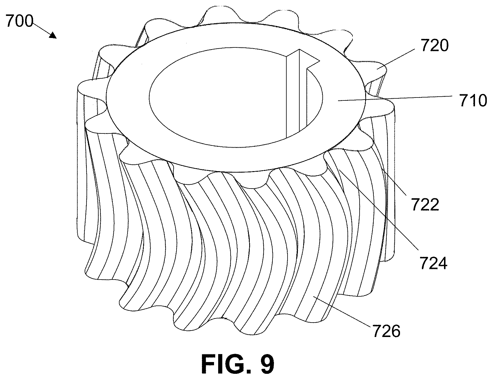
[0037] FIG. 9 shows an isometric view of an exemplary gear.
DETAILED DESCRIPTION
[0038] The primary drawback to involute tooth profiles in gear pumps is that the tooth of one gear does not fully sweep the tooth space of the mating gear. As the teeth progressively merge, a pocket of fluid is trapped and increasingly compressed by the continuing meshing action. The pressure of this fluid pocket is continually increased to a level sufficient to force a fluid flow rate between the gear teeth equal to the volume loss rate of the pocket (minus the effect of fluid compressibility). For gears with minimal backlash (and thus a tight mesh), as desired in gear pumps, this can result in very high pressures within the fluid pocket that can damage the tips of the gear teeth. The rapid pressurization of the fluid also contributes to the noise level of the pump. Various efforts have been done over time to model the meshing dynamics of involute spur gears in this regard.
[0039] While there are multiple avenues to mitigate the pressure oscillations, the most common is the relief groove. The primary driver of these oscillations is that, for spur gears, once the fluid pocket is trapped, the exit area of the pocket is very small (the thickness of the fluid film between teeth multiplied by the width of the gear). This increases the pressure within the pocket required to drive the necessary fluid flow to allow continued gear meshing, as the flow rate out of the pocket, Q.sub.p, is given by
Q p = C d A e 2 ( p p - p d ) .rho. ( 1 ) ##EQU00001##
[0040] where C.sub.d is the discharge coefficient of the tooth-to-tooth gap, A.sub.e is the exit area, p.sub.p is the pressure within the pocket, pd is the discharge pressure, and p is the density of the fluid. The required flow rate out of the pocket is set by the geometry of the meshing gears and the shaft speed of the pump; pp will rise to whatever is sufficient provide this flow rate. Therefore, to reduce the maximum value of p.sub.p during meshing process, the exit area of the pocket must be increased.
[0041] Enlarging the gap between the teeth during meshing is problematic for two reasons. First, while widening the gap between the teeth would allow fluid to escape the pocket, it would increase fluid leakage through the mesh. Due to the dynamic nature of the meshing zone, the only seal that separates the high pressure discharge region from the low pressure suction region is close and continual contact between the teeth at some point at all times. The second issue is that if the tooth separation (backlash) is too large, the gear mesh will lose a continuous line of action--at some point in the meshing action the gears lose contact. This would result in the idle gear slowing until the next meshing set of gears make contact to drive the gear, essentially slamming together each time. This would increase tooth wear and operational noise, and thus should be avoidable.
[0042] Instead of enlarging the gap between the teeth, an opening is made within the wear plate above and underneath the meshing zone. As the gear teeth progress through the mesh, fluid can escape through the groove into the discharge region. As long as the relief groove does not extend beyond the meshing zone into the suction region, leakage through the groove is limited. The exit area of the pocket then becomes the depth of the relief groove multiplied by the width.
[0043] While the addition of a relief groove can mitigate the pressure rise within the trapped fluid pocket during meshing, it does not entirely remove it. Once the teeth make contact, the effective exit area reduces to the groove area on the two plates which still necessitates a pressure rise--just a smaller one than if there were not relief grooves. The width of the groove is limited by the pump geometry, as it can only be as wide as the meshing zone. Likewise, the depth of the groove is limited by the design of the pump, as the bearing structure below competes for space. Groove depth thus trades against pump size, which is problematic for robotic applications where size and mass is at a premium.
[0044] The limitation of the relief groove is that, for spur gears, the tooth-to-tooth seal forms completely along the width of the gear at the moment of contact. Thus the trapped fluid pocket can only escape through the two ends of the pocket at the wear plate relief grooves. That still requires fluid in the center of the pocket between the two plates to travel the width of the gears in the timescale of the meshing action, and for high pump speeds this can result in large requisite pressures within the pocket. One solution is to shift away from a spur gear architecture and utilize one that enables gradual tooth meshing, such as a helical gear. During meshing, one end of the gears engage first and the tooth seal gradual engages as the gears rotate through the mesh. This has two impacts: first, it allows gradual engagement of the mesh and reduces tooth stress and noise at high speeds; second, as the meshing teeth sweep out the tooth space volume, the tooth seal has not fully engaged along the entire width, providing additional exit area for the fluid pocket. In essence, rather than trapping a fluid pocket and squeezing the fluid out through the ends, a helical gear mesh compresses the volume at one end and progressively moves to the other end, reducing exit area as the pocket volume reduces. This larger exit area reduces the required pressure in the pocket to vacate the volume and further attenuates pressure spikes. Helical gears are often used in conjunction with wear plate relief grooves, as otherwise there still exists a trapped fluid pocket at the end of the meshing action, just greatly reduced.
[0045] The primary limitation with the helical gear approach is that it introduces axial loads that must be compensated for. When gears mesh, all force exchange is normal to the surface of the tooth at the point of contact. For spur gears, this results in primarily tangential loads with some small radial loads, as the contact surface is aligned along the axial direction. For helical gears, the teeth are at an angle to the axial direction, called the helix angle; thus as the teeth mesh, force transfer occurs at a vector that contains large tangential and axial loads, in addition to minor radial loads. This axial load acts to force the helical gears into the wear plate on one side.
[0046] Sufficient axial loading reduces the thickness of the fluid film between the gears and the wear plates, which shifts the regime from hydrodynamic lubrication to elastohydrodynamic lubrication and potentially mixed lubrication, which is characterized by dramatically increased wear and galling. Galling rapidly increases frictional loads, increases motor loads, inhibits smooth operation, and decreases pump lifetime. Beyond considering wear, excessive compressive load on the film between the wear plate and the gear increases frictional losses and decreases mechanical efficiency.
[0047] Conventional pumps cut pressure compensation grooves in the wear plates at the location of compression. These grooves are connected to the discharge region and fill with high-pressure fluid that supplies a hydrostatic force to counter the axial loading of the gears. While this approach mitigates the risks of helical gears, it does so by expanding the leakage path between the discharge and suction regions, reducing volumetric efficiency. Rather than try to compensate for a weakness of helical gears, exemplary gears offer all the benefits mentioned thus far, but without any of the drawbacks that come from helical gears.
[0048] In order to meet and exceed all of the benefits of conventional gear pump technology, the gear should display the following characteristics: [0049] A circular profile of the addendum to match the dedendum, so that one tooth completely sweeps the volume between tooth flanks of the mating gear [0050] Gradual engagement of the teeth during meshing, enabling smoother operation and lower pressure pulsations [0051] Balanced axial force transfer during engagement to eliminate net axial loads on the gears
[0052] In order to achieve these goals, a new gear is described herein. Exemplary tooth profiles hybridize the profiles of the involute curve for smooth force transfer with the void-clearing capability of a circular-arc tip. Likewise, the gradual engagement of a helical gear may be made symmetrical to balance the axial loading.
[0053] A primary drawback of a helical gear is the net axial loading placed on the gears during meshing. Again, this axial load is imparted on the gear during meshing, as there is an axial component to the force exchange due to the orientation of the tooth surface. One way to passively balance this axial load is to make the gears symmetric about the central plane of the gear. For a helical gear, this results in a herringbone gear. By using what is essentially a gear made of two combined helical gears with opposite helix angles, the axial load of one half of the gear is balanced against the other, resulting in no net axial load. Herringbone gears have been used in power transmission applications for over a century, though not at such small scales.
[0054] The primary difficulty in fabricating a herringbone gear at this size scale is the `V` junction along the centerline of the gear; such sharp corners cannot be readily machined. An alternative approach is to change the side profile from a `V` to a shape that is continuously differentiable (i.e. smooth). Curvilinear gear teeth nominally have side profiles that are circular arcs that are both continuously differentiable and symmetric. This approach offers the same benefits of herringbone hears, namely gradual mesh contact and balanced axial loading, in a more readily manufacturable shape.
[0055] An exemplary design process of the CCAT gear is as follows. First, the overall gear geometry is selected, including the root circle radius, maximum outer radius, gear height, and the number of teeth. Second, the axial profile is formulated. Third, the hybrid tooth profile is created to fit the needs of the specific application, including any geometric or performance constraints. Fourth, the gear is modeled in a CAD software package. Finally, the generated CAD file is used in conjunction with a CNC milling machine to fabricate the gear.
[0056] The first step is to select the overall geometric parameters of the gear, such as root and outer radii, as well as height and the number of teeth. These parameters are sometimes dictated by external requirements, such as pump cavity dimensions, a desired pump flow rate, or a required torque capacity. Other terms may be selected arbitrarily and iterated on later in the process.
[0057] The second step is to create the axial profile mathematically. For computer design applications such as NX 10, the side profile curve may be defined parametrically in Cartesian coordinates. Due to the nature of the geometry in question, this may necessitate conversion from cylindrical to Cartesian coordinates.
[0058] The surface of a cylinder of radius r is defined by
x=r cos t
y=r sin t
z .di-elect cons. [0, w] (1)
where t is the parametric parameter, and w is the height of the cylinder. In this application, r is the root radius of the gear and w is the width of the gear that was chosen in the first step. Next, an axial profile is selected and defined in 2-d Cartesian coordinates by some function f.
y=f(x) (2)
[0059] Equation (2) is mapped to the cylinder surface defined by Equation set (1) by using the following parameter transformation,
y=r(.theta.-.theta..sub.0)
x=z (3)
where .theta. is the angular position of an arbitrary point on the axial profile, and .theta..sub.0 is the angular position of the start of the curve when z=0. The profile angle is then described as a function of axial position.
.theta. = f ( z ) r + .theta. 0 ( 4 ) ##EQU00002##
[0060] To express the profile in 3D Cartesian parametric form, Equation (4) is substituted into Equation set (1) as the parametric parameter. The axial profile is defined by convention as the locus of points that is the reference point of the tooth profile as it is propagated along the axis of the gear. The reference point of the tooth profile is where the tooth profile contacts the root circle. For an involute gear tooth, this where the involute curve crosses the root circle or is a function of extra tooth root geometry where applicable. For the example design of the CCAT gear, this reference point is at the minimum of the circular dedendum profile (point D FIG. 2). This makes .theta..sub.D the half-angle of the tooth profile, which can be compared to the number of chosen teeth as a design check to ensure that the selected number of teeth fit within the circle.
[0061] The third step is to create the hybrid tooth profile. There are multiple options for defining the tooth flank profile.
[0062] While the above discussions have focused on the limitations of the involute curve, one of the chief advantages of it has been the smooth transfer of force during meshing. Additionally, how a tooth sweeps the flank of a mating tooth is primarily a function of the design of the addendum and dedendum of the tooth. These curves can be any function as long as it fits the constraint that one conforms to the other during meshing of mating gears. The functional goal is to increase the degree that one gear sweeps out the volume between the teeth of the other gear. With these two goals of smooth meshing and tooth conformity, the exemplary tooth profile is a hybrid of circular and involute curves.
[0063] The process for defining the hybrid profile mathematically is to divide the curve into the constituent parts, define any required curve origins, and express each segment as a function of geometric parameters. These parameters may be freely variable, such as the base circle for involute curves, or may be dependent on external constraints or previous assumptions, such as the outer radius or the number of teeth. These expressions can then be used in curve fitting calculations to refine parameter selection.
[0064] An exemplary hybrid tooth profile 200 consists of three sections, as shown in FIG. 2: the addendum circular arc 210, the involute flank curve 220, and the dedendum circular arc 230. The two circular arcs have their separate origins located on the pitch circle. The addendum arc origin, O.sub.1, is located at the 12 o'clock position and is where the azimuthal position, .theta., is defined to be zero. The dedendum arc origin, O.sub.2, is defined to be at the angle which defines the end of the half tooth profile. The beginning and end points of the profile are labeled A and D, respectively, while the transition points between circular arcs and the involute curve are labeled B and C.
[0065] The arc length of the tooth in radians is determined by the number of teeth, n.sub.t,
.theta. D = .pi. n t ( 5 ) ##EQU00003##
which also defines the angular position of O.sub.2.
[0066] In the exemplary tooth profile, the addendum and dedendum curves are circular profiles, best expressed parametrically using a reference angle, .gamma.. For example, the addendum curve can be written as
x.sub.a=r.sub.a sin .gamma. (6)
y.sub.a=r.sub.p-r.sub.a cos .gamma. (7)
[0067] The flank curve, y.sub.f(x), must also be expressed in a similar manner. For the exemplary curve, the Cartesian coordinates of an involute curve can be expressed parametrically as
x.sub.f=r.sub.b(cos(t)+t sin(t)) (8)
y.sub.f=r.sub.b(sin(t)-t cos(t)) (9)
where t is the parametric parameter, and r.sub.b is the radius of the base circle. Note that the flank curve may need to be transformed using a variable rotation matrix to define the flank curve origin on the base circle, shown in FIG. 3. Once defined, all constituent curves must be defined with respect to the same reference origin and in terms of a single reference parameter. For the exemplary curve, this is the angular position, .theta..
[0068] In order to create a complete hybrid profile the component curves must be combined. The criteria for merging the curves are that the created hybrid curve is continuous and differentiable. Most constituent curves satisfy that requirement internally, which means that the solution criteria reduces solely to where the curves meet--points B and C in the exemplary profile. Mathematically, this means that at point B
y a ( x B ) = y f ( x B ) ( 10 ) dy a dx | x B = dy f dx | x B ( 11 ) ##EQU00004##
and similarly so at point C.
[0069] Using these criteria is unlikely to result in an analytical solution for the profile parameters, as the problem is likely under-constrained due to the number of geometric parameters, shown for the exemplary profile in Table 1. Instead, a numerical approach is used where the termination parameters for all constituent curves are calculated using the above equations. The squared differences between the corresponding values may be calculated and summed, and the remaining unknown parameters may be passed through a numerical solving algorithm to minimize the sum error. The resulting curve for the exemplary tooth profile is shown in FIG. 4. Once the smooth hybrid profile is generated, it is reflected across the y-axis to create a full tooth profile. A sampling of points along the profile is collected to be used in creating a spline curve in CAD software.
TABLE-US-00001 TABLE 1 Cuve splicing parameters and their range restrictions. Parameter Range Restriction .gamma..sub.a 0 .ltoreq. .gamma..sub.a .ltoreq. .pi./4 .gamma..sub.d 0.sub.D .ltoreq. .gamma..sub.d .ltoreq. .pi./4 t.sub.B t.sub.C .ltoreq. t.sub.B t.sub.C 0 .ltoreq. t.sub.C .theta..sub.C0 0 .ltoreq. .theta..sub.C0 .ltoreq. .theta..sub.D r.sub.b r.sub.r .ltoreq. r.sub.b .ltoreq. r.sub.p b a .ltoreq. b
[0070] As shown in FIG. 5, once the tooth profile is complete, the gear may be generated in a CAD software package, for example NX 10, in process 500. The root cylinder may be created at block 520, having a radius r.sub.r and height w. Next the bore for the shaft may be cut, along with the keyway, at block 530. Then the tooth side profile may be created as a 3D parametric curve at block 540. The tooth profile may then be created at block 550 using 67 data points calculated using the tooth profile parameters; these data points may be imported into NX and used to generate the profile. The circular arc sections may be created using the arc command, while the involute section may be created using a fit spline to the corresponding data points. The tooth profile is then closed with a circular arc of radius r.sub.r and then swept along the side profile, generating the first tooth 560. The component features of this tooth are then grouped and propagated in a circular arc to complete tooth formation at block 570. The process is illustrated visually in FIG. 6.
[0071] Due to the complexity of the design and the small tolerances required (less than 0.001 inches on the tooth profile), fabrication may be performed using a high-quality mill such as a Kitamura Mytrunnion 5-axis CNC mill. The Mytrunnion has a positional repeatability of 0.00002 inches, which allows for component tolerances less than 0.0005 inches.
[0072] An exemplary resulting gear is shown in FIGS. 7-9 at 700. As depicted, the gear 700 includes an annular gear body 710. A set of gear teeth 720 extend radially away from the gear body 710 and extending axially along the gear body 710. As shown, the gear 700 is an exterior gear with the teeth 720 extending radially outward from the annular body 710. However, an inner gear is also possible with the gear teeth extending radially inwardly from the annular body. Each tooth 720 has a cross-sectional profile taken transverse to the rotational axis of the gear body 710. The cross-sectional profile is shaped as described above, and is formed from a hybridization of two or more curves. As described above, exemplary embodiments include a profile having circular tips 722 and roots 724 with involute flanks 726. In preferred embodiments, the radius of the tooth tip arc is equal to or less than a radius of a tooth root arc. In other exemplary embodiments, however, the flank may be circular or cycloidal, rather than involute.
[0073] In any case, the gear tooth cross-sectional profile may configured such that the tip sweeps through the tooth root volume of the mating gear and such that the gear smoothly meshes with a complimentary gear. Preferably, the two or more curves of the hybrid tooth profile are combined such that the cross-sectional profile of the tooth is continuously differentiable.
[0074] Likewise, each tooth 720 has an axial tooth profile defining a circumferential positioning of the gear tooth at any location along the axis of the gear body 710. This profile is, as described above, continuously differentiable or smooth along the axis of the gear to reduce axial loading on gears induced by gear meshing. In exemplary embodiments, the axial tooth profile is also symmetric about an axial mid-plane of the gear to eliminate axial loading from gear meshing. Also as described above, the axial tooth profile may be
[0075] Although the invention has been shown and described with respect to a certain embodiment or embodiments, it is obvious that equivalent alterations and modifications will occur to others skilled in the art upon the reading and understanding of this specification and the annexed drawings. In particular regard to the various functions performed by the above described elements (components, assemblies, devices, compositions, etc.), the terms (including a reference to a "means") used to describe such elements are intended to correspond, unless otherwise indicated, to any element which performs the specified function of the described element (i.e., that is functionally equivalent), even though not structurally equivalent to the disclosed structure which performs the function in the herein illustrated exemplary embodiment or embodiments of the invention. In addition, while a particular feature of the invention may have been described above with respect to only one or more of several illustrated embodiments, such feature may be combined with one or more other features of the other embodiments, as may be desired and advantageous for any given or particular application.
* * * * *
D00000
D00001
D00002
D00003
D00004
D00005
D00006
D00007
D00008

XML
uspto.report is an independent third-party trademark research tool that is not affiliated, endorsed, or sponsored by the United States Patent and Trademark Office (USPTO) or any other governmental organization. The information provided by uspto.report is based on publicly available data at the time of writing and is intended for informational purposes only.
While we strive to provide accurate and up-to-date information, we do not guarantee the accuracy, completeness, reliability, or suitability of the information displayed on this site. The use of this site is at your own risk. Any reliance you place on such information is therefore strictly at your own risk.
All official trademark data, including owner information, should be verified by visiting the official USPTO website at www.uspto.gov. This site is not intended to replace professional legal advice and should not be used as a substitute for consulting with a legal professional who is knowledgeable about trademark law.