Automatic three-dimensional parking garage
Chen; Jiali
U.S. patent application number 16/724369 was filed with the patent office on 2020-04-23 for automatic three-dimensional parking garage. The applicant listed for this patent is Jiali Chen. Invention is credited to Jiali Chen.
| Application Number | 20200123798 16/724369 |
| Document ID | / |
| Family ID | 68554679 |
| Filed Date | 2020-04-23 |


| United States Patent Application | 20200123798 |
| Kind Code | A1 |
| Chen; Jiali | April 23, 2020 |
Automatic three-dimensional parking garage
Abstract
The invention discloses a slab nozzle inspection equipment with artificial measurement error avoidance, and includes a base, a left-right symmetrical bracket is fixed on the upper side of the base, and an adjustment cavity is arranged in the base. The end surface of the bracket is provided with two sets of four parking spaces, and the present invention adopts a lead screw active pulley and a wire. The belt connection between the auxiliary pulleys of the levers realizes the synchronization of the rotation of the left and right lead screws and ensures the stability of the car when it moves up and down. The hydraulic power is provided to switch the power of the left and right parking spaces to ensure that the left and right parking spaces work independently, Using a one-way bearing structure, the power is switched by whether to rotate synchronously to ensure that each parking space works independently.
| Inventors: | Chen; Jiali; (Wenzhou City, CN) | ||||||||||
| Applicant: |
|
||||||||||
|---|---|---|---|---|---|---|---|---|---|---|---|
| Family ID: | 68554679 | ||||||||||
| Appl. No.: | 16/724369 | ||||||||||
| Filed: | December 22, 2019 |
| Current U.S. Class: | 1/1 |
| Current CPC Class: | E04H 6/225 20130101; E04H 6/424 20130101 |
| International Class: | E04H 6/22 20060101 E04H006/22; E04H 6/42 20060101 E04H006/42 |
Foreign Application Data
| Date | Code | Application Number |
|---|---|---|
| Aug 27, 2019 | CN | 2019107986300 |
Claims
1. An automatic three-dimensional parking garage includes a base, and a left-right symmetrical bracket is fixedly arranged on the upper side of the base. An adjustment cavity is provided in the base, and two sets of four parking spaces are arranged in an array on the end surface of the bracket. No. 1 suspension bracket is fixed on the lower end surface of the parking chute, and a No. 1 connecting shaft is rotatably connected to the front side of the No. 1 suspension bracket. A connecting shaft, and the first connecting shaft is fixedly provided with a first pulley; a vehicle access device is provided on the front side of the No. 1 pulley, and the vehicle access device can be connected to the No. 2 connection shaft by rotating a roller disc connected to the No. 1 connection shaft, and is circular with the roller. The parking space lever which is slidably connected to the disk is rotated to the first lever which is connected to the parking space lever and is rotatably connected to the parking space chute. The parking space plate which is slidably connected to the parking space chute and is connected to the first lever is changed. The different movement state of the No. 1 lever drives the left and right movement to realize the vehicle unloading and loading; a limit device is provided on the parking space board, and the limit device can change the different movement states of the second leverage lever by rotating the four second levers connected to the parking space board to help fix the vehicle, and the top of the bracket A garage steel frame is fixedly installed, and a driving cavity is provided in the garage steel frame; a switch assembly is provided on the left inner wall of the driving chamber, and the switch assembly can be slidably connected to a hydraulic column on the right of the hydraulic cylinder through a hydraulic cylinder fixedly provided on the left inner wall of the driving chamber. The left and right movements switch the power connection to the left and right side garages. a screw motor is fixed to the inner wall of the top end of the driving cavity, and the left and right symmetrical symmetrical lead screws extending into the driving cavity are connected to the inner wall of the bottom end of the adjusting cavity. The upper end of the lead screw on the left side is power-connected and embedded in the inner wall of the top end of the drive cavity. The lead screw is threadedly connected to a bottom plate. A mobile motor is fixed in the first bottom plate. The upper side is provided with a power connection No. 3 connecting shaft. Two sets of one-way bearings installed opposite to each other are distributed from the top to the bottom. The upper side of the one-way bearing is fixed with a rotating disk. A second suspension bracket is fixedly arranged on the lower side of the rotating disc, and a car-board slide rail is fixedly arranged on the lower side of the second suspension bracket; a car plate moving device capable of controlling the movement of the parking plate is provided on the upper side of the car plate slide rail, and the car plate moving device can be fixedly installed in the place by sliding a slider connected to the slideway. The position of the barb plate on the slider pushes the parking space plate to realize the movement of the parking space plate.
2. The automatic three-dimensional parking garage according to claim 1, wherein a left-right symmetrical transmission shaft is rotatably connected to the inner wall of the lower end of the driving cavity, and the transmission shaft extends downward and is rotatably connected to the upper end surface of the base. The transmission shaft is oppositely installed with two sets of one-way bearings, the two sets of one-way bearings are provided with bevel gear sleeves, and the third side suspension is located on the right side of the first suspension bracket on the lower side of the parking space slideway. A bracket, the No. 3 suspension bracket is rotatably connected to a No. 4 connecting shaft, a No. 4 bevel gear is rotatably connected to the No. 4 connecting shaft, and a No. 3 pulley is rotatably connected to the front end of the No. 4 connecting shaft, and the No. 3 A belt is connected between the pulley and the No. 1 belt pulley, and a No. 4 suspension bracket near the lead screw is fixed on the lower side of the slideway, and a No. 5 rotation connection is provided on the No. 4 suspension bracket. A connecting shaft, a front end of the fifth connecting shaft is provided with a second bevel gear meshingly connected with the bevel gear sleeve, and a left side of the fourth suspension bracket is provided with a fifth suspension bracket fixedly connected to the parking track, The number five hanging branch The front side of the frame is rotatably connected with a No. 6 connecting shaft, and the No. 6 connecting shaft is fixedly provided with a No. 3 bevel gear meshingly connected with the No. 2 bevel gear, and a front side of the No. 3 bevel gear is provided at the No. 6 The No. 4 pulley at the front end of the No. connecting shaft, the No. 4 belt is connected between the No. 4 pulley and the No. 1 pulley, and the lead screw extends upward and into the driving cavity. The lead screw is dynamically connected to a lead screw motor fixedly disposed on the inner wall of the top end of the drive cavity. A lead screw pulley is provided on the lower side of the lead screw motor, and the lead screw on the right side is rotationally connected to the inner wall of the top of the drive cavity. A screw lead pulley is fixed on the upper side of the screw on the right side, and a screw lead belt is connected between the screw lead pulley and the screw lead pulley.
3. The automatic three-dimensional parking garage according to claim 2, wherein a belt is connected between the lead screw active pulley and the lead screw secondary pulley.
4. The automatic three-dimensional parking garage according to claim 2, characterized in that: two sets of the one-way bearings on the transmission shaft are oppositely installed.
5. The automatic three-dimensional parking garage according to claim 1, characterized in that: the parking plate can be slidably connected with the loading plate, and the parking plate is provided with left and right symmetrical loading plate slides, and the rotation The disk is provided with a left-right symmetrical rotating disk slide, and the vehicle-carrying plate slide and the rotating disk-slide can be slidably connected with the vehicle-carrying plate slide on the parking plate.
6. The automatic three-dimensional parking garage according to claim 1, characterized in that: the vehicle board moving device comprises a second floor which is fixedly arranged on the lower side of the second suspension bracket, and the second floor is rotatably connected to the second floor. There is a No. 7 connecting shaft, a No. 2 belt pulley is fixed on the No. 7 connecting shaft, and a No. 3 lever, which is located on the upper side of the No. 2 belt pulley, is fixed on the No. 7 connecting shaft The upper hinge is connected with a No. 4 lever rotatably connected to the slider, and a belt is connected between the No. 2 pulley and the one-way bearing on the upper side of the No. 1 base plate.
7. The automatic three-dimensional parking garage according to claim 1, characterized in that the switch assembly includes a motor fixedly arranged on the right side of the hydraulic column, and a right side of the motor is provided with a horizontal drive shaft connected by power, so The right end of the horizontal drive shaft is rotatably connected to the drive slider, and a drive slide is slidably connected to the drive slider on the right inner wall of the drive cavity. A vertical bevel gear that is symmetrical and located to the right of the motor.
8. The automatic three-dimensional parking garage according to claim 1, wherein the one-way bearing includes a bearing box rotatably connected to the transmission shaft, and the bearing box is meshed with the first bevel gear, A rotating cavity is provided in the bearing box, twelve rotating teeth are provided on an inner wall of the rotating cavity, a rotating wheel is disposed in the rotating cavity on the transmission shaft, and six annular arrays are arranged on the rotating wheel. A push rod, and the thrust rod is rotatably connected to the runner. A bearing spring is provided between the thrust rod and the runner, and the thrust rod can abut the rotating teeth.
9. The automatic three-dimensional parking garage according to claim 1, wherein the limit device comprises a fifth lever which is rotatably connected to the second lever, and a load is provided between the second lever and the parking plate. Car plate spring.
10. The automatic three-dimensional parking garage according to claim 9, wherein the fifth lever is a protruding structure.
Description
CROSS-REFERENCES TO RELATED APPLICATIONS
[0001] The present application claims priority from Chinese application No. 2019107986300 filed on Aug. 27, 2019 which is hereby incorporated by reference in its entirety.
FIELD OF TECHNOLOGY
[0002] The invention relates to the field of automatic parking, and in particular relates to an automatic three-dimensional parking garage.
TECHNICAL FIELD
[0003] With the advancement of technology, more and more cars have entered millions of households, and as a result, many three-dimensional parking garages have been born. However, most of the three-dimensional parking inventory currently has problems such as small parking spaces and a narrow field of vision, resulting in inconvenient parking. Even old drivers with years of driving experience still find parking difficult. There are various hidden dangers to parking in such a narrow parking space. The present invention illustrates a device capable of solving the above problems.
CONTENT OF THE INVENTION
Technical Problem
[0004] At present, most of the three-dimensional parking stocks have problems such as small parking spaces and narrow fields of vision, which cause parking inconvenience.
[0005] In order to solve the above problem, this example designs an automatic three-dimensional parking garage, which includes a base, and a left-right symmetrical bracket is fixed on the upper side of the base. The base has an adjustment cavity therein. No. 1 suspension bracket is fixed on the lower end surface of the parking space chute. The front side of the No. 1 suspension bracket is rotatably connected with a No. 1 connecting shaft, and the upper side of the No. 1 connecting shaft is provided with the connecting shaft. The No. 2 connecting shaft of the No. 1 suspension bracket is rotationally connected. The No. 1 connecting shaft is fixedly provided with a No. 1 pulley. The front side of the No. 1 pulley is provided with a vehicle access device. The vehicle access device can be connected to the vehicle by rotation. The roller disc of the first connecting shaft is rotatably connected with the parking lever of the second connecting shaft and slidingly connected with the roller disc, and the parking disc is rotatably connected with the parking lever and is rotatably connected with the parking track. The No. 1 lever is slidably connected to the parking space chute and rotates the parking plate connected to the No. 1 lever to change different movement states of the No. 1 lever to drive the left and right movements to implement vehicle unloading and storage. A limit device is provided on the parking space board, and the limit device can change the different movement states of the second leverage lever by rotating the four second levers connected to the parking space board to help fix the vehicle, and the top of the bracket A garage steel frame is fixedly provided. The garage steel frame is provided with a drive cavity. A switch assembly is provided on the left inner wall of the drive cavity. The switch assembly can be fixed by a hydraulic pressure provided on the left inner wall of the drive cavity. The cylinder is slidably connected to the hydraulic column on the right side of the hydraulic cylinder, and the power connection to the left and right garages is switched by the left and right movement. A screw motor is fixed on the inner wall of the top of the driving cavity, and the bottom of the adjusting cavity is fixed. An inner wall is rotatably connected with a left-right symmetrical lead screw extending into the driving cavity, and an upper end of the lead screw on the left side is dynamically connected with an inner wall embedded in the top end of the driving cavity. A bottom plate is provided with a moving motor fixed in the No. 1 bottom plate, and a No. 3 connecting shaft for power connection is arranged on the upper side of the moving motor. A one-way bearing, a rotating disk is fixed on the upper side of the one-way bearing on the upper side, a second suspension bracket is fixed on the lower side of the rotating disk, and a car board is fixed on the lower side of the second suspension bracket A slide rail is provided on the upper side of the car plate slide rail with a car plate moving device capable of controlling the movement of the parking plate. The car plate moving device can be fixed by sliding a slider connected to the slide rail. The position of the barb plate provided on the slider pushes the parking space plate to realize the movement of the parking space plate.
[0006] Preferably, a left-right symmetrical transmission shaft is rotatably connected to the inner wall of the lower end of the driving cavity, the transmission shaft extends downward and is rotatably connected to the upper end surface of the base, and two sets of unidirectional bearings are oppositely installed on the transmission shaft. The two sets of one-way bearings are provided with a bevel gear sleeve, and the third side of the parking space is fixedly provided with a number three suspension bracket on the right side of the number one suspension bracket, and the number three suspension bracket is rotatably connected with a number four A connecting shaft, wherein the No. 4 connecting shaft is provided with a No. 1 bevel gear that is rotationally connected, and a front end of the No. 4 connecting shaft is rotatably connected with a No. 3 pulley, between the No. 3 pulley and the No. 1 pulley A No. 1 belt is connected, and a No. 4 suspension bracket near the lead screw is fixed on the lower side of the slide rail. The No. 4 suspension bracket is provided with a No. 5 connecting shaft that is rotationally connected, and a front end of the No. 5 connecting shaft The second bevel gear is meshed with the bevel gear sleeve. The fourth suspension bracket is provided with a fifth suspension bracket fixedly connected to the parking space slide on the left side, and the front side of the fifth suspension bracket is rotatably connected. There are number six connecting shafts, the six The connecting shaft is fixedly provided with a No. 3 bevel gear meshingly connected with the No. 2 bevel gear. A front side of the No. 3 bevel gear is provided with a No. 4 pulley located at the front end of the No. 6 connecting shaft. A second belt is connected between the pulley and the first pulley, the lead screw extends upward and into the driving cavity, and the lead screw on the left side is dynamically connected to the inner wall of the top of the driving cavity. A lead screw motor is provided on the lower side of the lead screw motor. The lead screw on the right side is rotatably connected to the inner wall of the top of the driving cavity. A lead screw pair is fixed on the upper side of the lead screw on the right side. A pulley, a lead screw belt is connected between the lead screw active pulley and the lead screw auxiliary pulley.
[0007] Preferably, a belt is connected between the lead screw active pulley and the lead screw secondary pulley.
[0008] Preferably, two sets of the one-way bearings on the transmission shaft are oppositely installed.
[0009] Preferably, the parking plate can be slidably connected with the loading plate, the parking plate is provided with a left-right symmetrical car plate slide, and the rotating disk is provided with a left-right symmetrical disk slide. The car board slide and the rotating disc slide can be slidably connected to the car board slide on the parking plate.
[0010] Wherein, the vehicle board moving device includes a No. 2 bottom plate fixedly arranged on the lower side of the No. 2 suspension bracket, and a No. 7 connecting shaft which is rotatably connected to the No. 2 bottom plate. There is a No. 2 pulley, the No. 7 connecting shaft is fixedly provided with a No. 3 lever located on the upper side of the No. 2 pulley, and the No. 3 lever is hinged with a No. 4 lever that is rotatably connected to the slider, A belt is connected between the second pulley and the one-way bearing on the upper side of the first base plate.
[0011] Wherein, the switch assembly includes a motor fixedly arranged on the right side of the hydraulic column, a power transmission horizontal drive shaft is provided on the right side of the motor, and the right end of the horizontal drive shaft is rotatably connected to the drive slider, and A driving slideway slidably connected to the driving slider is provided on the inner wall of the right side of the driving cavity, and the horizontal transmission shaft is fixedly provided with a vertical bevel gear that is symmetrical on the right side of the motor.
[0012] Wherein, the one-way bearing includes a bearing box that is rotatably connected to the transmission shaft, and the bearing box is meshed with the No. 1 bevel gear. The bearing box is provided with a rotating cavity, and an inner wall of the rotating cavity There are twelve rotating teeth, the transmission shaft is provided with a rotating wheel located in the rotating cavity, the annular array on the rotating wheel is provided with six thrust rods, and the thrust rod is rotatably connected with the rotating wheel. A bearing spring is provided between the thrust rod and the runner, and the thrust rod can abut against the rotating teeth.
[0013] Wherein, the position limiting device includes a fifth lever which is rotatably connected to the second lever, and a vehicle-carrying plate spring is arranged between the second lever and the parking plate.
[0014] Preferably, the fifth lever is a protruding structure.
[0015] The beneficial effect of the present invention is that the present invention adopts the belt connection between the lead screw active pulley and the lead screw secondary pulley to realize the synchronization of the rotation of the left and right lead screws and ensure the stability of the car when it moves up and down. The hydraulic machine is installed to perform power switching between the left and right parking spaces to ensure that the left and right parking spaces work independently. The one-way bearing structure is used to ensure that each parking space works independently through the power switching through synchronous rotation. The one-way bearing structure is used to ensure synchronous rotation. Carry out changes in the process of changing the direction of the car board or moving the car board in and out, to realize the automatic storage and unloading of cars, and improve the existing parking difficulties and hidden dangers.
BRIEF DESCRIPTION OF THE DRAWINGS
[0016] For ease of description, the present invention is described in detail by the following specific embodiments and the accompanying drawings.
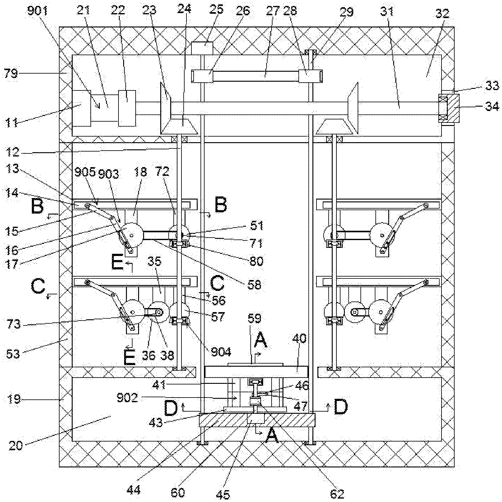
[0017] FIG. 1 is a schematic diagram of the overall structure of an automatic stereo parking garage according to the present invention;
[0018] FIG. 2 is a schematic structural diagram of the direction "A-A" of FIG. 1;
[0019] FIG. 3 is a schematic structural diagram in a direction "B-B" of FIG. 1;
[0020] FIG. 4 is a schematic structural diagram in a direction "C-C" of FIG. 1;
[0021] FIG. 5 is a schematic structural diagram of the "D-D" direction of FIG. 1;
[0022] FIG. 6 is a schematic structural diagram of the "E-E" direction of FIG. 1
[0023] FIG. 7 is a schematic structural diagram of a parking space floor and a lifting floor;
[0024] FIG. 8 is a schematic structural diagram of a car board;
[0025] FIG. 9 is a schematic structural diagram of a one-way bearing.
DETAILED DESCRIPTION OF THE INVENTION
[0026] The present invention is described in detail below with reference to FIGS. 1 to 9. For convenience of description, the orientations described below are defined as follows: the up-down, left-right, and front-back directions described below are consistent with the up-down, left-right, and front-back directions of the projection relationship of FIG. 1 itself
[0027] The invention relates to an automatic three-dimensional parking garage, which is mainly used in the process of automatic parking. The invention will be further described below with reference to the accompanying drawings of the invention:
[0028] The automatic three-dimensional parking garage according to the present invention includes a base 19, and a left-right symmetrical bracket 53 is fixed on the upper side of the base 19. An adjustment cavity 20 is provided in the base 19, and an end surface of the bracket 53 is distributed in an array. There are two sets of four parking space chute 13. The lower end surface of the parking space chute 13 is fixedly provided with a No. 1 suspension bracket 18, and a No. 1 connecting shaft 68 is rotatably connected to the front side of the No. 1 suspension bracket 18 On the upper side of 68, there is a second connecting shaft 30 which is rotatably connected to the first suspension bracket 18. The first connecting shaft 68 is fixedly provided with a first pulley 70. A vehicle is provided on the front side of the first pulley 70. Access device 903. The vehicle access device 903 can rotate a roller disc 17 connected to the first connecting shaft 68, and a parking space connected to the second connecting shaft 30 and slidingly connected to the roller disc 17. Lever 16, the first lever 15 which is connected to the parking space lever 16 and is rotatably connected to the parking space slide 13, and the parking plate 14 which is slidably connected to the parking space 13 and rotates the first lever 15 is changed The different movement states of the No. 1 lever 15 drive the The left and right movements of the vehicle 14 enable storage and unloading of vehicles. The parking plate 14 is provided with a limiting device 905. The limiting device 905 can be changed by rotating the four second levers 77 connected to the parking plate 14. The different movement states of the second lever 77 are used to assist in fixing the vehicle. A garage steel frame 79 is fixed at the top of the bracket 53. The garage steel frame 79 is provided with a driving cavity 32, and a left inner wall of the driving cavity 32 is provided. There is a switch assembly 901. The switch assembly 901 can be slidably connected to a hydraulic column 21 on the right side of the hydraulic cylinder 11 through a hydraulic cylinder 11 fixedly provided on the left inner wall of the driving chamber 32, Moving and switching the power connection to the left and right side garages, a screw motor 25 is fixed on the inner wall of the top end of the driving cavity 32, and a left-right symmetrical wire extending into the driving cavity 32 is connected to the inner wall of the bottom end of the adjusting cavity 20 by rotation. The upper end of the screw rod 29 on the left side is dynamically connected with a 25 embedded in the inner wall of the top end of the driving cavity 32. The screw rod 29 is threadedly connected with a bottom plate 44 which is fixed inside. A moving motor 45 is provided, said moving motor 45 The upper side is provided with a power connection No. 3 connecting shaft 60. The No. 3 connecting shaft 60 has two sets of one-way bearings 904 installed oppositely from top to bottom, and the upper side of the one-way bearing 904 is fixed on the upper side. A rotating disc 40 is provided, and a second suspension bracket 41 is fixedly arranged on the lower side of the rotating disc 40. A vehicle-mounted plate slide rail 55 is fixedly arranged on the lower side of the second suspension bracket 41. 55 is provided on the upper side with a car board moving device 902 capable of controlling the movement of the parking plate 14, and the car board moving device 902 can be fixedly fixed to the slide block 65 by slidingly connected to the slide 64. The position of the barb plate 59 on the slider 65 pushes the parking space plate 14 to realize the movement of the parking space plate 14.
[0029] Beneficially, a left-right symmetrical transmission shaft 12 is rotatably connected to the inner wall of the lower end of the driving cavity 32, the transmission shaft 12 extends downward and is rotatably connected to the upper end surface of the base 19, and two transmission shafts 12 are oppositely installed. A set of one-way bearings 904. The two sets of one-way bearings 904 are provided with a bevel gear sleeve 80, and a third-number suspension bracket 72 on the right side of the first-number suspension bracket 18 is fixed on the lower side of the parking track 13. The No. 3 suspension bracket 72 is rotatably connected to a No. 4 connecting shaft 69, the No. 4 connecting shaft 69 is provided with a No. 1 bevel gear 51 for rotation, and the No. 4 connecting shaft 69 is rotatably connected to the No. 3 pulley 71 at the front end. A belt 58 is connected between the third pulley 71 and the first pulley 70, and a fourth suspension bracket 56 near the lead screw 29 is fixed on the lower side of the slideway 13. The No. 5 suspension bracket 56 is provided with a No. 5 connecting shaft 75 which is rotatably connected. The front end of the No. 5 connection shaft 75 is provided with a No. 2 bevel gear 57 meshingly connected with the bevel gear sleeve 80. The No. 4 suspension bracket 56 On the left side, a No. 5 suspension bracket 35 fixedly connected to the parking space slide 13 is provided. The front side of the suspension bracket 35 is rotatably connected with a No. 6 connecting shaft 74, and the No. 6 connecting shaft 74 is fixedly provided with a No. 3 bevel gear 36 meshingly connected with the No. 2 bevel gear 57; A fourth belt pulley 73 located at the front end of the sixth connection shaft 74 is provided on the side. A second belt 38 is connected between the fourth belt pulley 73 and the first belt pulley 70, and the lead screw 29 faces upward. Extending into the driving cavity 32, the lead screw 29 on the left side is dynamically connected to a lead screw motor 25 fixedly provided on the inner wall of the top end of the driving cavity 32, and a lead screw driver is provided on the lower side of the lead screw motor 25 Pulley 26, the lead screw 29 on the right side is rotatably connected to the inner wall of the top end of the driving cavity 32, and a lead screw auxiliary pulley 28 is fixed on the upper side of the lead screw 9 on the right side. The lead screw active pulley 26 and A lead screw belt 27 is connected between the lead screw secondary pulleys 28.
[0030] Beneficially, the lead screw belt 27 is connected between the lead screw active pulley 26 and the lead screw auxiliary pulley 28, so that the rotation synchronization of the lead screw 29 is realized, and the number one bottom plate 44 is guaranteed to be up and down. Stability when moving.
[0031] Beneficially, the two sets of the one-way bearings 904 on the transmission shaft 12 are oppositely installed, so that when the transmission shaft 12 rotates in different directions, the two sets of the one-way bearings 904 work independently.
[0032] Beneficially, the parking space plate 14 can be slidably connected with the loading plate 54. The parking space plate 14 is provided with a left-right symmetrical loading plate slideway 76, and the rotating disk 40 is provided with a left-right symmetrical rotation circle. The disk slideway 49, the vehicle-carrying plate slideway 76 and the rotating disk slideway 49 can be slidably connected to the vehicle-carrying plate slideway 55 on the parking plate 14.
[0033] According to the embodiment, the vehicle-board moving device 902 will be described in detail below. The vehicle-board moving device 902 includes a number-two bottom plate 43 which is fixed to the lower side of the number-two suspension bracket 41 and is rotatably connected to the number-two floor. The number seven connecting shaft 67 on 43, the number seven connecting shaft 67 is fixedly provided with a number two pulley 63, and the number seven connecting shaft 67 is fixedly provided with a number three on the upper side of the number two pulley 63 The lever 47 is articulated on the third lever 47 with a fourth lever 46 that is rotatably connected to the slider 65, and the second pulley 63 and the one-way bearing 904 on the upper side of the first base plate 44. There are belts 62 connected.
[0034] According to the embodiment, the switch assembly 901 will be described in detail below. The switch assembly 901 includes a motor 22 fixedly disposed on the right side of the hydraulic column 21, and a horizontal drive shaft 31 connected to the power is provided on the right side of the motor 22. The right end of the horizontal transmission shaft 31 is rotatably connected to the driving slider 34. A driving slideway 33 slidably connected to the driving slider 34 is provided on the right inner wall of the driving cavity 32, and the horizontal transmission shaft 31 Vertical bevel gears 23 symmetrically located on the right side of the motor 22 are fixed on the upper side, and whether the vertical bevel gear 23 is meshed with the horizontal bevel gear 24 is changed to realize the switching of the power of the left and right side garages.
[0035] According to the embodiment, the one-way bearing 904 will be described in detail below. The one-way bearing 904 includes a bearing box 48 rotatably connected to the transmission shaft 12, and the bearing box 48 is meshed with the first bevel gear 51. The bearing box 48 is provided with a rotating cavity 37. The inner wall of the rotating cavity 37 is provided with twelve rotating teeth 39. The transmission shaft 12 is provided with a rotating wheel 66 located in the rotating cavity 37. The rotating wheel 37 There are six thrust rods 52 on the annular array on 66, and the thrust rods 52 are rotatably connected to the runner 66. A bearing spring 61 is provided between the thrust rods 52 and the runner 66. The thrust rod 52 can abut against the rotating teeth 39.
[0036] According to the embodiment, the limit device 905 is described in detail below. The limit device 905 includes a fifth lever 50 which is rotatably connected to the second lever 77. A load is provided between the second lever 77 and the parking plate 14. The vehicle plate spring 78 realizes that the second lever 77 returns to the initial motion state after the vehicle loading plate enters.
[0037] Beneficially, the fifth lever 50 is provided with a protruding design, which can be used for pushing the fifth load lever 50 by the vehicle board moving device 902, so that the second lever 77 generates different motion states.
[0038] The following describes in detail the steps of using an autosteric parking garage in this article with reference to FIGS. 1 to 9:
[0039] When the second-tier vehicle on the left side enters the warehouse, the hydraulic cylinder 11 is activated to move the hydraulic column 21 to the left until the vertical bevel gear 23 meshes with the horizontal bevel gear 24. At this time, the motor 22 is started to reverse the horizontal transmission shaft 31 Turn clockwise, and then pass the vertical bevel gear 23, horizontal bevel gear 24, drive shaft 12, one-way bearing 904, second bevel gear 57, third bevel gear 36, sixth connecting shaft 74, fourth belt pulley 73, The first pulley 70, the first connecting shaft 68, the second belt 38, the roller disc 17, the parking lever 16, and the first lever 15 drive the parking space to the right, and at the same time start the lead screw motor 25 to rotate the lead screw 29 clockwise. Further, the lead screw driving pulley 26, the lead screw belt 27, the lead screw secondary pulley 28, and the No. 1 bottom plate 44 drive the car plate moving device 902 to move upward so that the rotating disk 40 is flush with the parking plate 14. At this time, the motor is turned off 22. The screw motor 25 and the moving motor 45 are started at the same time so that the No. 3 connecting shaft 60 rotates counterclockwise, and then passes through the No. 3 belt 62, the No. 2 pulley 63, the No. 3 lever 47, the No. 4 lever 46, the slider 65, The runner 66 drives the car plate 54 to move forward to the rotating disc 40 The elastic potential energy is accumulated by the return spring 42. At this time, the lead screw motor 25 is started to rotate the lead screw 29 counterclockwise, and the moving motor 45 is turned off. Then, the lead screw active pulley 26, the lead screw belt 27, the lead screw secondary pulley 28, The No. 1 floor 44 drives the car-board moving device 902 down to the ground, and the return spring 42 elastically recovers to move backward, so that the slider 65, the No. 4 lever 46, and the No. 3 lever 47 return to the initial state. The vehicle plate 54 starts the moving motor 45 so that the third connection shaft 60 rotates clockwise, and in turn passes the two oppositely arranged one-way bearings 904 to drive the rotating disc 40 to rotate 180.degree. clockwise. At this time, the moving motor 45 is turned off, and at the same time Start the lead screw motor 25 to rotate the lead screw 29 clockwise, and then use the lead screw active pulley 26, lead screw belt 27, lead screw secondary pulley 28, and No. 1 bottom plate 44 to drive the car plate moving device 902 to move upward so that the rotation circle The disk 40 is flush with the parking plate 14. At this time, the lead screw motor 25 is turned off, and the moving motor 45 is started to rotate the third connection shaft 60 counterclockwise, and then pass the third belt 62, the second pulley 63, the third lever 47, Number four leverage 46. The slider 65 and the runner 66 drive the carrier plate 54 to move back to the parking plate 14 and make 50 images move backward. The second lever 77 limits the carrier plate 54 and makes the return spring 42 accumulate elasticity. Potential energy, at this time, the mobile motor 45 is turned off, the motor 22 is started to rotate the horizontal transmission shaft 31 counterclockwise, and then passes through the vertical bevel gear 23, the horizontal bevel gear 24, the transmission shaft 12, the one-way bearing 904, the second bevel gear 57, The third bevel gear 36, the second belt 38, the roller disc 17, the parking space lever 16, and the first space lever 15 drive the parking space to the left. At this time, the return spring 42 elastically resumes moving forward, so that the slider 65 and the fourth lever 46 3. The third lever 47 returns to the initial state, turns off the motor 22, starts the lead screw motor 25, and further drives the car board moving device 902 through the lead screw active pulley 26, the lead screw belt 27, the lead screw secondary pulley 28, and the first bottom plate 44. Go down to the ground. Turn off the lead screw motor 25 and start the moving motor 45 to make the No. 3 connecting shaft 60 rotate clockwise, and then pass two oppositely-located one-way bearings 904 in turn to drive the rotating disc 40 to rotate 180.degree. clockwise, making it convenient for the next vehicle. In and out of the warehouse.
[0040] When the third-tier vehicle on the left side enters the warehouse, the hydraulic cylinder 11 is activated, and the hydraulic column 21 is moved to the left until the vertical bevel gear 23 meshes with the horizontal bevel gear 24. At this time, the motor 22 is started to reverse the horizontal transmission shaft 31 Turn clockwise, and then pass the vertical bevel gear 23, horizontal bevel gear 24, drive shaft 12, one-way bearing 904, No. 1 bevel gear 51, No. 4 connecting shaft 69, No. 3 pulley 71, No. 1 belt 58, 1 Pulley 70, No. 1 connecting shaft 68, No. 2 belt 38, roller disc 17, parking lever 16, lever No. 15 drive the parking space to the right, and at the same time start the lead screw motor 25 to rotate the lead screw 29 clockwise, and then The lead screw driving pulley 26, the lead screw belt 27, the lead screw secondary pulley 28, and the first bottom plate 44 drive the car plate moving device 902 to move upward so that the rotating disk 40 is flush with the parking plate 14, and the motor 22 is turned off at this time. The screw motor 25 and the moving motor 45 are started at the same time so that the third connection shaft 60 rotates counterclockwise, and then passes through the third belt 62, the second pulley 63, the third lever 47, the fourth lever 46, the slider 65, and the rotation. Wheel 66, which drives the car plate 54 forward to the rotating disc 40, The return spring 42 is allowed to accumulate elastic potential energy. At this time, the lead screw motor 25 is started to rotate the lead screw 29 counterclockwise, and the moving motor 45 is turned off. Then, the lead screw active pulley 26, the lead screw belt 27, the lead screw secondary pulley 28, The bottom plate 44 drives the carrier plate moving device 902 down to the ground, and the return spring 42 elastically recovers to move backward, so that the slider 65, the fourth lever 46, and the third lever 47 return to the initial state. At this time, the vehicle is driven into the vehicle. Plate 54, start the moving motor 45 to make the No. 3 connecting shaft 60 rotate clockwise, and then pass two oppositely arranged one-way bearings 904 in turn to drive the rotating disc 40 to rotate 180.degree. clockwise. At this time, the moving motor 45 is turned off and started at the same time. The lead screw motor 25 rotates the lead screw 29 clockwise, and then drives the car plate moving device 902 upward to rotate the disc through the lead screw active pulley 26, lead screw belt 27, lead screw secondary pulley 28, and first floor 44 40 is flush with the parking plate 14. At this time, the lead screw motor 25 is turned off, and the moving motor 45 is started to rotate the third connection shaft 60 counterclockwise, and then pass the third belt 62, the second pulley 63, the third lever 47, and the fourth. Number lever 46 The slider 65 and the runner 66 drive the vehicle-carrying plate 54 backward to the parking plate 14 and make 50 move backward. The second lever 77 limits the vehicle-carrying plate 54 and causes the return spring 42 to accumulate elastic potential energy. At this time, the moving motor 45 is turned off, and the motor 22 is started to rotate the horizontal transmission shaft 31 counterclockwise, and then pass the vertical bevel gear 23, the horizontal bevel gear 24, the transmission shaft 12, the one-way bearing 904, the first bevel gear 51, and the fourth Connecting shaft 69, No. 3 pulley 71, No. 1 belt 58, No. 1 belt pulley 70, No. 1 connecting shaft 68, No. 2 belt 38, roller disc 17, parking lever 16, and No. 1 lever 15 drive the parking space to the left At this time, the return spring 42 elastically resumes moving forward, so that the slider 65, the No. 4 lever 46, and the No. 3 lever 47 return to the initial state, and the motor 22 is turned off, and the lead screw motor 25 is started so that the lead screw 26 and the lead screw are passed through the lead screw. The belt 27, the auxiliary screw pulley 28, and the No. 1 bottom plate 44 drive the carrier plate moving device 902 down to the ground. Turn off the lead screw motor 25 and start the moving motor 45 to make the No. 3 connecting shaft 60 rotate clockwise, and then pass the two oppositely arranged one-way bearings 904 in turn to drive the rotating disc 40 to rotate 180.degree. clockwise to facilitate the next vehicle advance. Warehouse, out of warehouse.
[0041] The beneficial effect of the present invention is that the present invention adopts the belt connection between the lead screw active pulley and the lead screw secondary pulley to realize the synchronization of the rotation of the left and right lead screws and ensure the stability of the car when it moves up and down. The hydraulic machine is installed to perform power switching between the left and right parking spaces to ensure that the left and right parking spaces work independently. The one-way bearing structure is used to ensure that each parking space works independently through the power switching through synchronous rotation. The one-way bearing structure is used to ensure synchronous rotation. Carry out changes in the process of changing the direction of the car board or moving the car board in and out, to realize the automatic storage and unloading of cars, and improve the existing parking difficulties and hidden dangers.
[0042] In the above manner, those skilled in the art can make various changes according to the working mode within the scope of the present invention.
* * * * *
D00000
D00001
D00002
D00003
D00004
D00005
D00006
D00007
XML
uspto.report is an independent third-party trademark research tool that is not affiliated, endorsed, or sponsored by the United States Patent and Trademark Office (USPTO) or any other governmental organization. The information provided by uspto.report is based on publicly available data at the time of writing and is intended for informational purposes only.
While we strive to provide accurate and up-to-date information, we do not guarantee the accuracy, completeness, reliability, or suitability of the information displayed on this site. The use of this site is at your own risk. Any reliance you place on such information is therefore strictly at your own risk.
All official trademark data, including owner information, should be verified by visiting the official USPTO website at www.uspto.gov. This site is not intended to replace professional legal advice and should not be used as a substitute for consulting with a legal professional who is knowledgeable about trademark law.