Breakaway Athletic Track Hurdle And Training Device
Covalschi; Edward ; et al.
U.S. patent application number 16/657465 was filed with the patent office on 2020-04-23 for breakaway athletic track hurdle and training device. The applicant listed for this patent is AU ATHLETE LLC. Invention is credited to Steve Bollinger, Edward Covalschi, Johnathan Small, Madelyn Wesoloski.
| Application Number | 20200122051 16/657465 |
| Document ID | / |
| Family ID | 70278500 |
| Filed Date | 2020-04-23 |


| United States Patent Application | 20200122051 |
| Kind Code | A1 |
| Covalschi; Edward ; et al. | April 23, 2020 |
BREAKAWAY ATHLETIC TRACK HURDLE AND TRAINING DEVICE
Abstract
A training device includes a first leg, a second leg, and a top board connectable to the first leg and the second leg. The top board has a first position transverse to a path of travel between the first leg and the second leg providing a releaseable obstruction along the path of travel. The top board further includes a breakaway joint operable to release at least a portion of the top board to a second position on an impact to the top board thereby providing an open passageway through the top board along the path of travel.
| Inventors: | Covalschi; Edward; (Shelby Township, MI) ; Small; Johnathan; (Zionsville, IN) ; Bollinger; Steve; (Elkhart, IN) ; Wesoloski; Madelyn; (Naperville, IL) | ||||||||||
| Applicant: |
|
||||||||||
|---|---|---|---|---|---|---|---|---|---|---|---|
| Family ID: | 70278500 | ||||||||||
| Appl. No.: | 16/657465 | ||||||||||
| Filed: | October 18, 2019 |
Related U.S. Patent Documents
| Application Number | Filing Date | Patent Number | ||
|---|---|---|---|---|
| 62747273 | Oct 18, 2018 | |||
| Current U.S. Class: | 1/1 |
| Current CPC Class: | A63B 2209/08 20130101; A63B 2069/0037 20130101; A63B 5/16 20130101; A63B 2210/50 20130101; A63B 2225/093 20130101; A63B 5/22 20130101; A63B 2244/088 20130101; A63B 69/0028 20130101; A63B 71/0054 20130101; A63K 3/043 20130101 |
| International Class: | A63K 3/04 20060101 A63K003/04; A63B 69/00 20060101 A63B069/00 |
Claims
1. A training device comprising: a first leg; a second leg; and a top board connectable to the first leg and the second leg, the top board having a first position transverse to a path of travel between the first leg and the second leg providing a releaseable obstruction along the path of travel, wherein the top board comprises: a breakaway joint operable to release at least a portion of the top board to a second position on an impact to the top board thereby providing an open passageway through the top board along the path of travel.
2. The training device of claim 1, wherein the top board further comprises: a first top board having a first end and a second end, the first end rotatably connected to the first leg; and a second top board having a first end and a second end, the first end rotatably connected to the second leg, the breakaway joint positioned between the second end of the first board and a second end of the second board.
3. The training device of claim 2, wherein the breakaway joint further comprises: a permanent magnet connected to the second end of one of the first or the second top board; and a ferromagnetic member connected to the second end of the other of the first or the second top board in proximity to the permanent magnet, wherein in the top board first position, the ferromagnetic member is attracted to the permanent magnet thereby providing the obstruction along the path of travel.
4. The training device of claim 1, further comprising: a top board hinge connected to at least one end of the top board and the respective second end of the first leg or the second leg, the top board hinge operable to allow rotation of at least a portion of the top board about an axis of rotation relative to the respective first or the second leg.
5. The training device of claim 4, wherein the axis of rotation is a first axis of rotation, and wherein the training device further comprises: a leg hinge connected to one of the first or the second leg and the top board hinge, the leg hinge operable to allow rotation of the top board hinge and the at least a portion of the top board about a second axis of rotation relative to the first or the second leg.
6. The training device of claim 5, wherein the first axis of rotation is generally perpendicular to the second axis of rotation.
7. The training device of claim 1, further comprising: a leg hinge connected to at least one end of the top board and the respective second end of the first leg or the second leg, the top board hinge operable to allow rotation of at least a portion of the top board about an axis of rotation relative to the respective first or the second leg.
8. The training device of claim 1, wherein the training device is an athletic track hurdle.
9. The training device of claim 1, further comprising a base, wherein the first leg and the second leg are each connected to the base, and the first leg and the second leg are laterally spaced apart from one another with respect to the base.
10. The training device of claim 9, wherein the first leg and the second leg are each pivotally connected to the base allowing the first and the second legs to rotate relative to the base between an operable position and a folded storage position.
11. The training device of claim 9, wherein each of the first and the second legs further comprise a lower member and an upper member, the upper member is moveable along a height axis relative to the lower member to selectively adjust the vertical height of the top board relative to the base.
12. A breakaway athletic track hurdle comprising: a base; a first leg connected to the base; a second leg connected to the base laterally distant from the first leg; a first top board having a first end and a second end; a second top board having a first end and a second end, the first and the second top board having a first operable position extending laterally between the first and second leg transverse to a path of travel between the first and the second leg; a first top board hinge connected to the first top board first end; a second top board hinge connected to the second top board first end; a first leg hinge rotatably connected to the first leg about a leg hinge axis of rotation; a second leg hinge rotatably connected to the second leg about a leg hinge axis of rotation; the first and second top board hinges rotatably connected to respective of the first and the second leg hinge and respectively rotatable about an axis of rotation relative to the first and the second leg hinge; a breakaway joint comprising: a first permanent magnet connected to a portion of the first top board second end; a first ferromagnetic member connected to a portion of the first top board second end; a second permanent magnet connected to a portion of the second top board second end positioned opposite the first ferromagnetic member; a second ferromagnetic member connected to a portion of the second top board second end positioned opposite the first permanent magnet, wherein on a physical impact to one of the first or the second top board, the breakaway joint releases thereby respectively rotating the first and the second top boards to a second position thereby providing an open passageway through the first and the second top board along the path of travel.
13. An apparatus comprising: a first leg; a second leg; and a top board comprising a breakaway joint, wherein the breakaway joint is configured to: connect in a first position whereby the top board is generally perpendicular to the first leg and the second leg, and separate in a second position whereby at least a portion of the top board is not generally perpendicular to the first leg and the second leg.
14. The apparatus of claim 13, wherein the breakaway joint is operable to separate in response to an impact to the top board.
15. The apparatus of claim 13, wherein when the breakaway joint is in the second position, a first portion of the top board and a second portion of the top board are separated from one another.
16. The apparatus of claim 13, wherein when the breakaway joint is in the first position, a first portion of the top board and a second portion of the top board are connected to one another.
17. The apparatus of claim 13, wherein when the breakaway joint is in the first position, a magnetic force holds a first portion of the top board and a second portion of the top board together.
18. The apparatus of claim 13, further comprising a dual hinge connecting the top board to the first leg.
19. The apparatus of claim 18, wherein the dual hinge permits the top board to rotate with respect to the first leg along both a first axis of rotation and a second axis of rotation.
20. The apparatus of claim 19, wherein the first axis of rotation and the second axis of rotation are generally perpendicular to one another.
Description
CROSS-REFERENCE TO RELATED APPLICATION
[0001] This application claims the benefit of U.S. Provisional Patent Application No. 62/747,273, filed Oct. 18, 2018, the entire contents of which are hereby incorporated by reference in its entirety.
TECHNICAL FIELD
[0002] This application generally relates to athletic track and field hurdles and athletic training devices.
BACKGROUND
[0003] The sport of athletic track and field is popular and highly competitive. Athletic track hurdle races are viewed as one of the most challenging and physically demanding of the running-type events. Conventional hurdle designs have long been problematic in potential injury to athletes due to the high-speed impact of the runner's legs with a hard top board of a hurdle and/or entanglement with the subsequent toppling forward of the hurdle.
[0004] Other hurdle-like training devices are also popular in collegiate and professional physical conditioning. These devices may be smaller and lower-height devices used in closely-positioned repetitive rows for speed, agility, and coordination training for athletes. These devices suffer from disadvantages that athletes may step on the rigid structures and sprain ankles and knees.
SUMMARY
[0005] Disclosed herein are various embodiments for a breakaway athletic track hurdle and training device which resolves or improves on prior athletic track hurdle and training devices.
[0006] In an example embodiment of a breakaway hurdle, the hurdle includes a base and two vertically-oriented legs laterally spaced across the base. The legs may be telescopically adjustable in height relative to the base. The hurdle includes a dual hinge design including a pair of leg hinges, one hinge rotatably connected to each leg. The dual hinge further includes a pair of top board hinges, one top board hinge rotatably connected to each leg. In various embodiments, the top board includes a first top board connected to one of the top board hinges and a second top board connected to the other of the top board hinges.
[0007] In various embodiments of a hurdle, a breakaway joint is positioned between the first top board and the second top board. The breakaway joint may include at least one permanent magnet connected to one of the first or the second top board and a ferromagnet member positioned on the other of the first or second top boards opposite the magnet. When the first and second top board are positioned in a first or operative position, a magnetic force between the magnet and ferromagnetic member causes the magnet and the ferromagnetic member to be attracted to one another such that the magnet and the ferromagnetic member are connected to one another to keep the top boards in a horizontal position obstructing a runner moving toward the hurdle along a path of travel.
[0008] On impact of a runner with one of the first or second top boards, the impacted top board rotates about the top board hinge to release or overcome the magnetic force connecting the magnet and the ferromagnetic member of the breakaway joint, causing the first and the second top boards to separate. Through the force of gravity, the released first and second top boards rotate downwardly about the leg hinges to a second position thereby removing the obstruction thereby providing an unobstructed pathway for the runner to pass through the hurdle without a significant impact with the top bar or possible entanglement with the base. Thus, when the first and second top boards separate, the first and second top boards may rotatably move, by way of the dual hinge design, around a first axis parallel with the legs of the hurdle and around a second axis perpendicular or normal to the legs of the hurdle.
[0009] In various embodiments, physical training devices may be formed that are similar to track hurdles but with different dimensions than a track hurdle. For example, such a training device may include a base, legs of a height significantly less than a track hurdle, a top bar positioned at a much lower height relative to the ground than a track hurdle top bar, at least one of each of the top bar hinges and leg hinges, and a breakaway joint as described above. In use, if a training athlete steps on the top bar, the top bar breaks-away in the manner generally described above thereby eliminating or reducing possible injury to knees, ankles, or feet of the athlete.
[0010] These and other aspects of the present disclosure are disclosed in the following detailed description of the embodiments, the appended claims and the accompanying figures.
BRIEF DESCRIPTION OF THE DRAWINGS
[0011] The invention is best understood from the following detailed description when read in conjunction with the accompanying drawings. It is emphasized that, according to common practice, the various features of the drawings are not to-scale. On the contrary, the dimensions of the various features may be arbitrarily expanded or reduced for clarity.
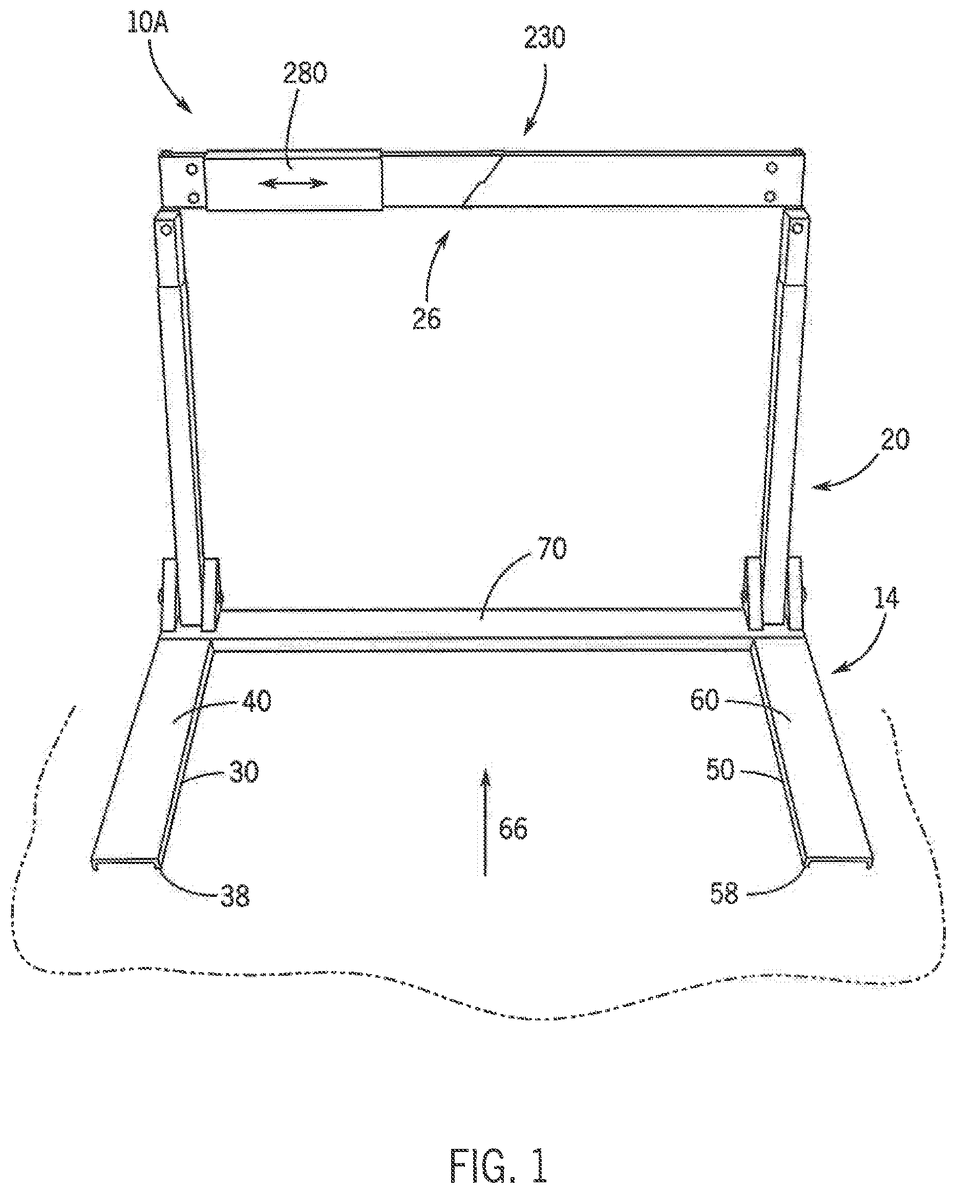
[0012] FIG. 1 illustrates a front perspective view of an example athletic track hurdle in a first or operative position, according to various embodiments;
[0013] FIG. 2 illustrates a rear perspective view of another example athletic track hurdle in a first or operative position, according to various embodiments;
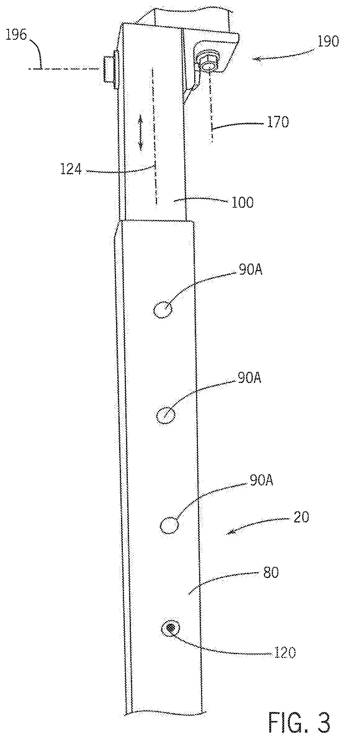
[0014] FIG. 3 illustrates a partial side perspective view of a leg of the example athletic track hurdle of FIG. 2, according to various embodiments;
[0015] FIG. 4 illustrates a partial side perspective view of an example a dual hinge design for use in an athletic track hurdle, according to various embodiments;
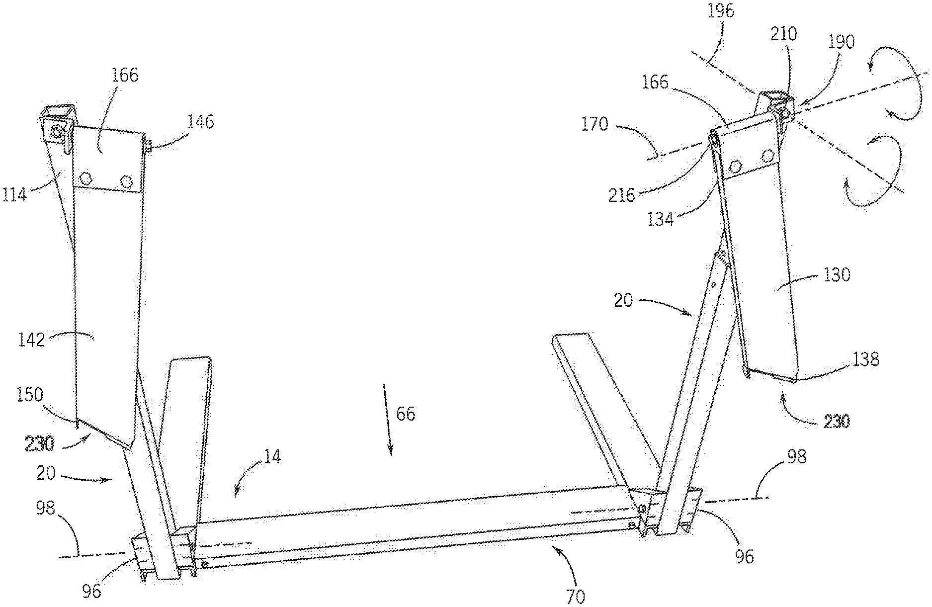
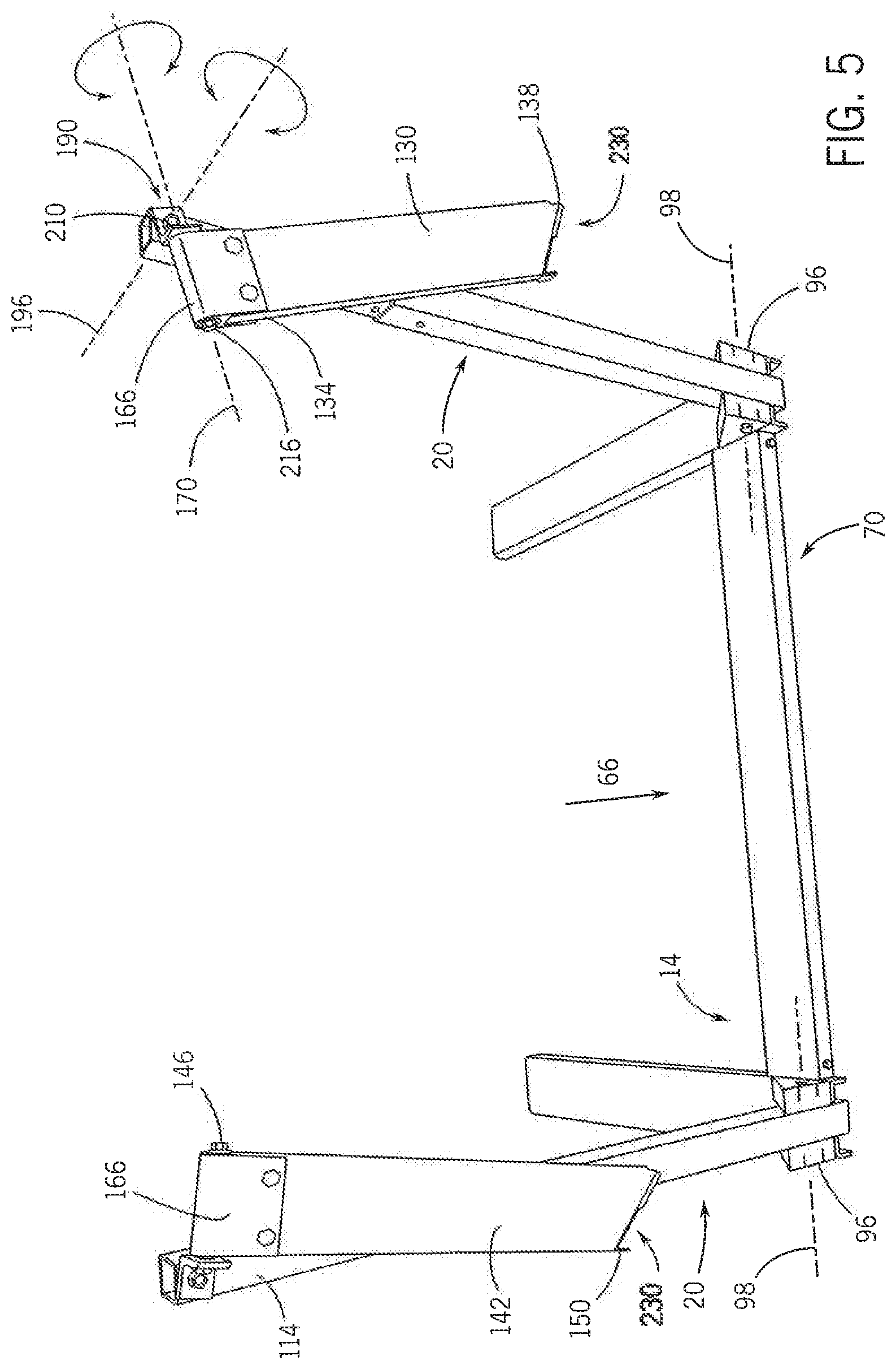
[0016] FIG. 5 illustrates a rear perspective view of the example athletic track hurdle of FIG. 2 in a second or released position according to various embodiments;
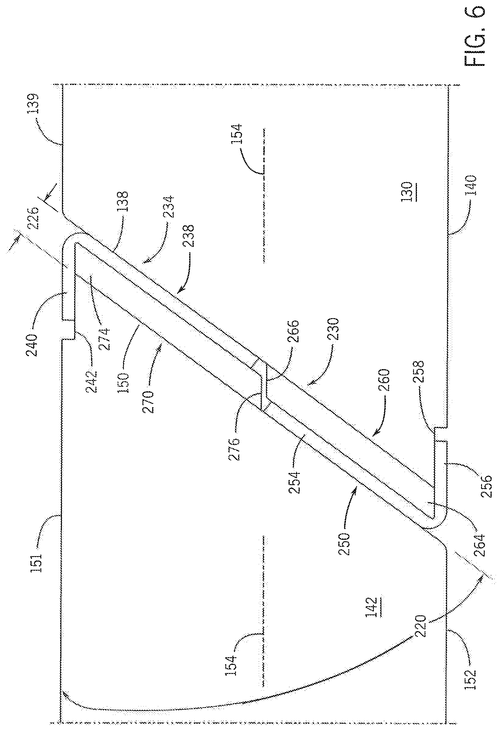
[0017] FIG. 6 illustrates an enlarged rear perspective view of a breakaway joint of the example athletic track hurdle of FIG. 2, according to various embodiments;
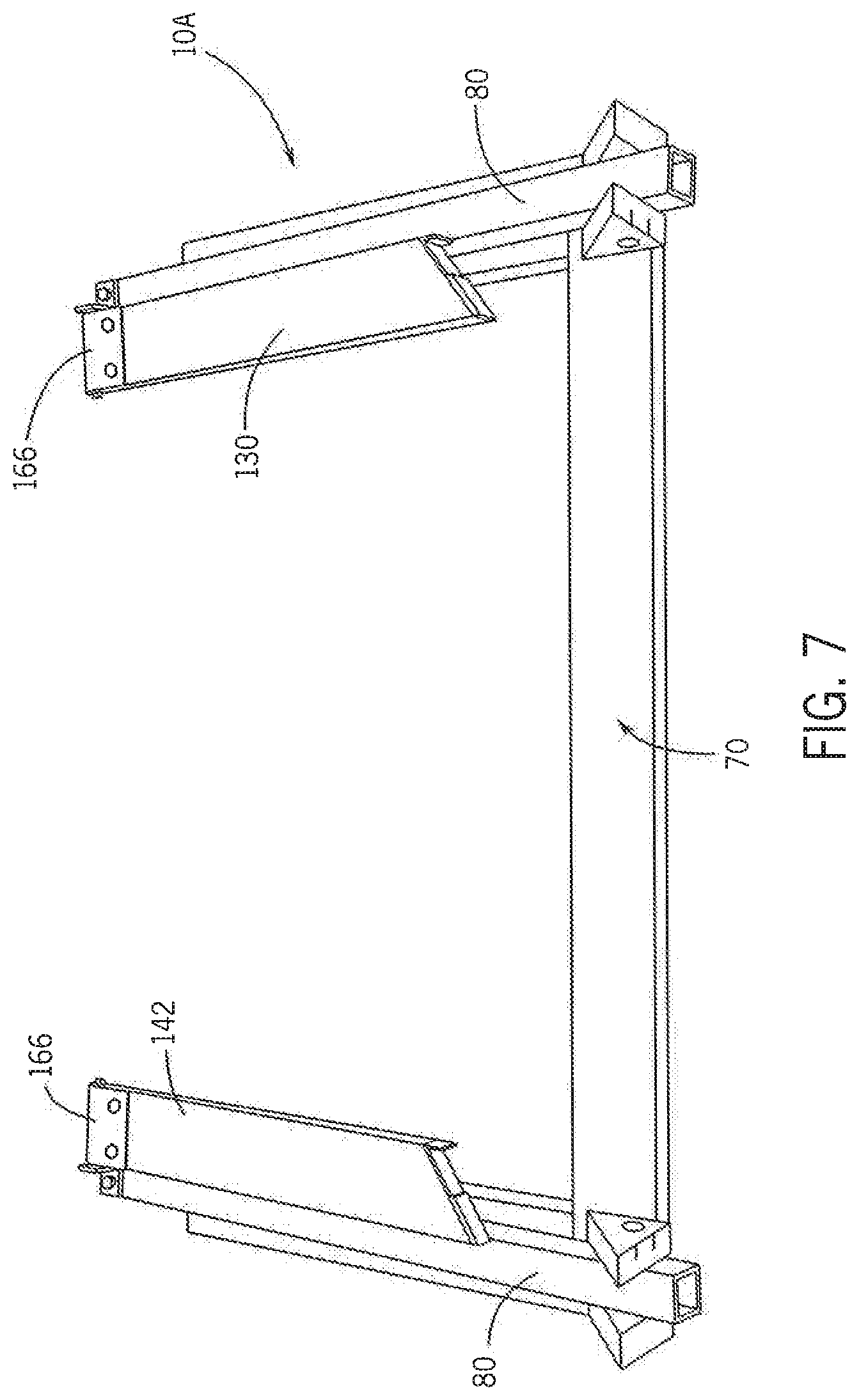
[0018] FIG. 7 illustrates a rear perspective view of the example athletic track hurdle shown in FIG. 1 in a second or released position and in a folded or storage position, according to various embodiments;
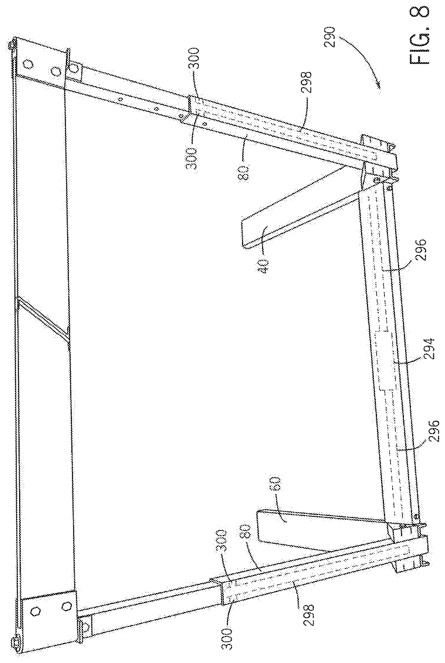
[0019] FIG. 8 illustrates a rear perspective view of an example athletic track hurdle with a top board height adjustment mechanism, according to various embodiments; and
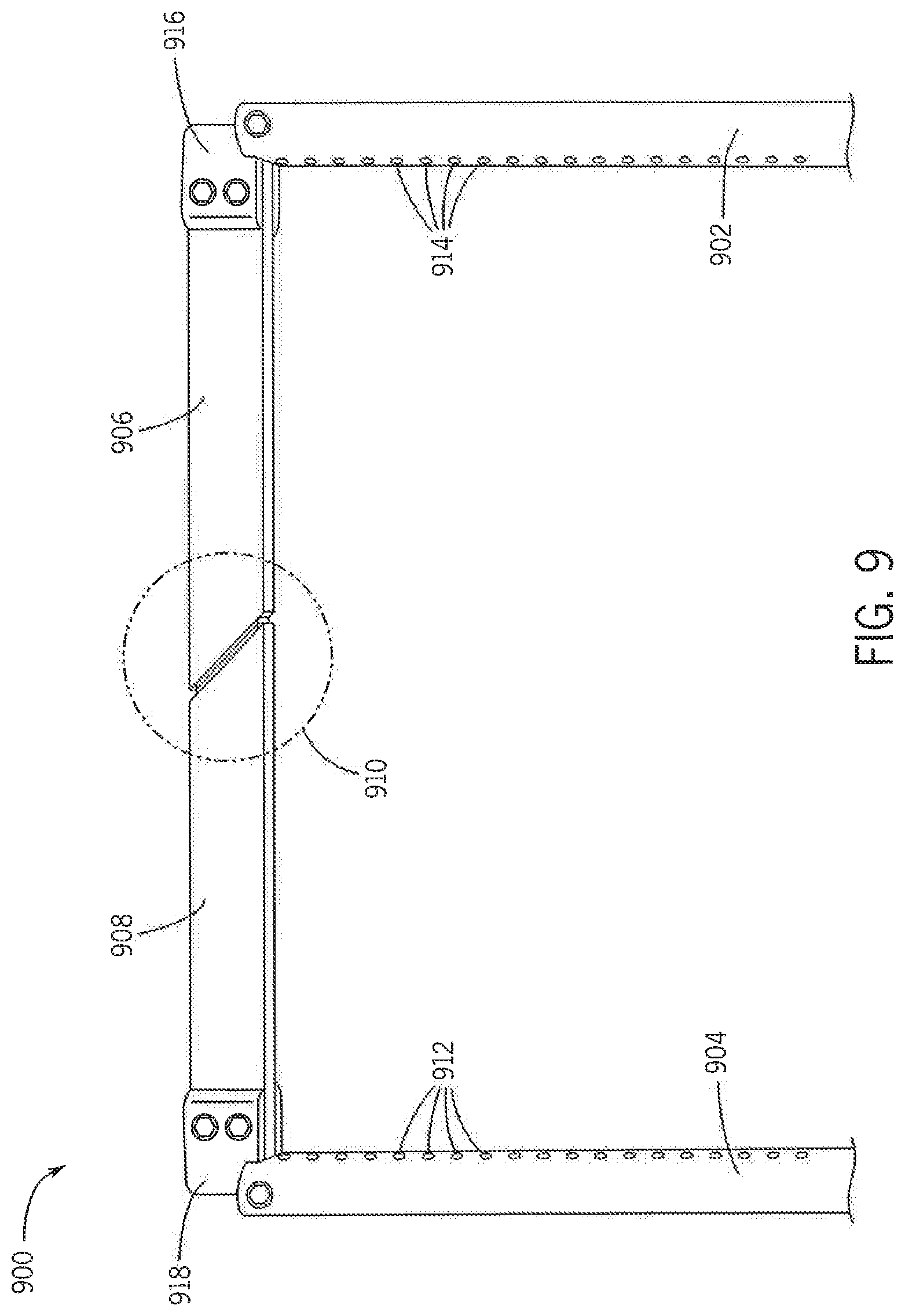
[0020] FIG. 9 illustrates a front perspective view of an example upper portion of an athletic track hurdle, according to various embodiments.
DETAILED DESCRIPTION
[0021] The following description of example methods and apparatuses are not intended to limit the scope of the description to the precise form or forms detailed herein. Instead, the following detailed description is intended to be illustrative.
[0022] There is a need for an improved athletic track hurdle that, on impact by a runner, the top board releases allowing the runner to "run through" the hurdle without a substantial impact or toppling over of the hurdle. The same breakaway concept is equally applicable to smaller training devices which athletes jump over.
[0023] With reference to the figures, various embodiments of improved breakaway athletic track hurdles and training devices are described herein. The athletic track hurdles and training devices disclosed herein may be used in competition, physical training, or in any other context in which it is desired use a breakaway track hurdle type device as disclosed herein. Various examples of breakaway athletic training devices according to various embodiments are shown and described with respect to FIGS. 1-8. Such athletic training devices may be useful for track and field athletes, and athletes in general for competition and/or physical training without many of the disadvantages of prior devices.
[0024] FIG. 1 illustrates a front perspective view of an example athletic track hurdle 10A in a first or operative position. FIG. 2 illustrates a rear perspective view of another example athletic track hurdle 10 in a first or operative position. When discussing features of the athletic track hurdle 10 and the athletic track hurdle 10A that may be common to one another, the two embodiments of FIGS. 1 and 2 are referred to herein as the hurdle 10, 10A even though there are some differences between the embodiments, which are further described herein. In these examples, the hurdle 10, 10A includes a base 14, a pair of vertically-oriented legs 20, and a breakaway top board 26 in a first operative position. The operative position may be a position at which training or competition typically occurs, such that an athlete may move toward the hurdle 10, 10A and jump and/or step over the breakaway top board 26. In these examples, the base 14 includes a first foot 30 having a first end 34, a second end 38, a bottom surface that rests on the ground, two opposing lateral outer surfaces, and a top surface 40 opposing the bottom surface of the first foot 30. The base 14 further includes a second foot 50 having a first end 54, a second end 58, a bottom surface that rests on the ground, two opposing lateral outer surfaces, and a top surface 60 opposing the bottom surface of the second foot 50. The second foot 50 may be similar in shape, orientation, and/or construction to the first foot 30. In these examples, the second foot 50 is laterally spaced apart from the first foot 30 providing sufficient space for a runner (not shown) to pass between along a path of travel 66.
[0025] In just one example, the hurdle 10, 10A may have a lateral distance between the outermost lateral outer surfaces of the first foot 30 and the second foot 50 may be anywhere from 38 to 50 inches (e.g., 38 inches, 39 inches, 40 inches, 41 inches, 42 inches, 43 inches, 44 inches, 45 inches, 46 inches, 47 inches, 48 inches, 49 inches, 50 inches). The lateral distance between the first foot 30 and the second foot 50 may vary depending on the training or competition purposes, applicable athletic competition rules, and/or other factors.
[0026] In various embodiments, alternate forms of bases rather than the base 14 may be used. For example, some embodiments may not be in the form of a traditional track hurdle. In various embodiments, the base 14 may be a single, continuous member, such as in the shape of a "U", "C", "W", "V", or other configurations that suit a particular application or desired shape. In various embodiments, the base 14 may have fewer, different, or additional components than those shown in FIGS. 1 and 2. For example, various embodiments may have a different or no crossmember, may have feet of different shapes or orientations with respect to the rest of a hurdle and/or the crossmember, etc.
[0027] Still referring to FIGS. 1 and 2, the hurdle 10, 10A base 14 further includes a crossmember 70 having a first end 74 connected to the first foot 30 and a second end 75 opposed to the first end 74 and connected to the second foot 50. The crossmember may also include a bottom surface that rests upon the ground, opposing lateral surfaces, and a top surface 78. In the examples of FIGS. 1 and 2, the first foot 30, the second foot 50, and the crossmember 70 are formed in a "U" section shape and are constructed from extruded aluminum. In various embodiments, other sizes, shapes, configurations, and orientations may be used. In various embodiments, other materials may be used, such as polymers, elastomers, composites, ferrous and other non-ferrous metals, and other materials suitable for the particular application or specification desired.
[0028] In the example hurdle 10, 10A of FIGS. 1 and 2, legs 20 may include a first leg 79 and a second leg 79A. Although aspects of the first leg 79 are discussed herein in detail, the second leg 79A has similar components and functionality as the first leg 79. The first leg 79 includes a lower member 80 having a first end 84 and a second end 88. The first end 84 is connected to the first foot 30. In various embodiments, the first end 84 of the first foot 79 may be connected to the crossmember 70 instead of or in addition to being connected to the first foot 30. In the example of FIG. 2, the first leg 79 is connected to the first foot 30 by a bracket 96. The bracket 96 securely mounts the first leg 79's lower member 80 to the first foot 30. The bracket 96 permits rotation of the lower member 80 relative to the first foot 30 about an axis 98, allowing the first leg 79 to fold down for transportation or storage as shown in FIG. 7 and described below. The second leg 79A is similarly attached to the second foot 50 with a bracket. In various embodiments, different connection mechanisms may be used. In various embodiments, depending on the size and configuration of the crossmember 70, the first foot 30, and the second foot 50, the first leg 79 and/or the second leg 79 may be connected to the crossmember 70 with a bracket instead of or in addition to being connected to the first foot 30 and the second foot 50.
[0029] In the example of FIG. 2, the lower member 80 is hollow, with a square cross-sectional shape, and includes at least one height mounting hole 90. FIG. 3 illustrates a partial side perspective view illustrating the leg 79 of the example athletic track hurdle 10 of FIG. 2. As shown in FIG. 3, the lower member 80 may also include a plurality of height mounting holes 90A to suit the particular height adjustment needed for the particular application or competition. Accordingly, height mounting holes may be on any surface of the legs 79, 79A (e.g., on an inside surface as shown in FIG. 2 with the height mounting hole 90, on an outside surface as shown in FIG. 3 with the height mounting holes 90A, or on a front or back surface of the legs 79, 79A).
[0030] The leg 79 of the hurdle 10, 10A may further include an upper member 100 that includes a first end 104 and a second end 108. In the example, upper member 100 is telescopically received inside lower member 80 and selectively moves relative to lower member 80 along height axis 124 as shown in FIG. 2.
[0031] The upper member 100 further includes a front side 110 (shown in FIG. 4) positioned/facing toward the direction in which the foot 30 extends and opposing the path of travel 66 from which a runner (not shown) would approach the hurdle 10, 10A. The upper member 100 further includes a rear side 114 on the opposite side of the front side 110 of the upper member 100. As best seen in the example shown in FIG. 2, the upper member 100 includes a plurality of height mounting holes 118 which allow the position of the upper member to be selectively fixed or locked relative to the lower member 80 along the height axis 124. The height mounting holes 118 may therefore align with the height mounting holes 90, 90A of the lower member 80 so that a pin or other mechanism may pass therethrough to selectively fix or lock the height of the upper member 100.
[0032] As best seen in FIG. 3, the hurdle 10, 10A may include a locking member 120. In the example, the locking member 120 includes a spring-biased pin or button mounted on the upper member 100 which is biased to extend laterally outward toward the lower member 80 and is aligned to engage the plurality of mounting holes 90A to selectively adjust or set the height of the upper member 100 relative to the lower member 80, thereby setting the height of the top breakaway top board 26 relative to the base 14 and ground or track supporting the base 14.
[0033] It is understood that locking member 120 may take many different forms including, for example, manual pins or other devices which are manually inserted through aligned holes in both of the lower member 80 and upper member 100 to adjust the height of upper member 100 and subsequently the top board 26 as desired. Another example of a height locking device is shown in FIG. 8 and discussed further below. It is further understood that locking member 120 in the form of a biasing button or pin may be positioned on either the lower member 80 or upper member 100. In an alternate example, the locking member may be electronic, for example an electronically actionable solenoid that is triggered electronically through a hard-wired connection to an activation button or wirelessly through a remote electronic input pad or device. The locking member 120 may also be duplicated on the other side of the upper member 100, such that multiple locking members extend through opposing mounting holes in the lower member 80.
[0034] As shown in FIGS. 2, 5, and 6, the breakaway top board 26 includes first top board 130 having a first end 134, a second end 138, an upper surface 139 and a lower surface 140. Breakaway top board 26 further includes a second top board 142 also including a first end 146, a second end 150, an upper surface 151 and a lower surface 152. In a first operative or competition position shown in FIGS. 1 and 2, the first 130 and second 142 top boards extend substantially horizontally along a lateral axis 154 between and spanning the first leg 79 and second leg 79A as generally shown.
[0035] As shown in FIGS. 2, 4, and 5, the hurdle 10, 10A further includes a double-hinge top board system with a first double hinge 160 that connects the first leg 79 to the first top board 130 and a second double hinge that connects the second leg 79A to the second top board 142. The first double hinge 160 is shown in and described with respect to FIG. 4, but the second double hinge is similar to the first double hinge in functionality. Each of the first double hinge 160 and the second double hinge include a top board hinge 166 and a leg hinge 190. As shown in FIG. 4, the top board hinge 166 is rigidly connected to the first end 134 of the first top board 130. Similarly, a second top board hinge is rigidly connected to the first end 146 of the second top board 142. The top board hinge 166 includes an axis of rotation 170, a channel 174 for receipt of the first end 134 of the first top board 130, and fasteners 180 to rigidly connect the first top board 130 to the top board hinge 166. In various embodiments, the top board hinge 166 is made from aluminum, but in other embodiments may be made from other materials such as polymers, other metals, or any other compositions or other materials. The top board hinge may also take other forms and/or orientations, for example, only connecting to one side of the top board, such that the channel 174 is not present but there is still a mechanism for connection to the first top board 130 (compared to the channel 174 that connects the top board hinge 166 to both sides of the first top board 130 as shown in FIG. 4).
[0036] The double-hinge 160 further includes the leg hinge 190. The leg hinge 190 is rotatably connected to the second end 108 of the leg upper member 100 on the rear side 114. The leg hinge 190 is rotatable about an axis of rotation 196 relative to the respective leg 79, 79A. When the hurdle 10, 10A is in the first or operative position, the axis of rotation 196 is generally perpendicular, or normal, to the axis of rotation 170, the first leg 79, the second leg 79A, the first top board 130, the second top board 142, and the crossmember 70. Further when the hurdle 10, 10A is in the first or operative position, the axis of rotation 196 is generally parallel to the path of travel 66 of a runner, the first foot 30, and the second foot 50. In the example of FIG. 4, the leg hinge 190 is a 90 degree or "L" shaped bracket with a first portion 204 in abutting contact with leg rear side 114, and a second portion 208 which abuttingly supports a bottom of the top board hinge 166. The leg hinge 190 may take other forms and configurations than the "L" shape as illustrated and described. The leg hinge 190 may be made from aluminum or any other suitable or desired materials.
[0037] As further described below, top board hinges may rotate about axis of rotation 170 relative to leg hinge 190, and leg hinge 190 may rotate about axis of rotation 196 relative to leg 79, 79A. When the hurdle 10, 10A is in the first or operative position, the axis of rotation 170 is generally parallel to the first leg 79 and the second leg 79A. Further when the hurdle 10, 10A is in the first or operative position, the axis of rotation 170 is generally perpendicular, or normal, to the first top board 130, the second top board 142, the axis of rotation 196, the crossmember 170, the first foot 30, and the second foot 50. In the example as best seen in FIGS. 2 and 4, a first pivot fastener 210 rotatably connects the top board hinge 166 to the leg hinge 190. A second pivot fastener 216 may be used to connect the leg hinge 190 to the upper member 100 of the leg 79. In various embodiments, the first pivot fastener 210 and the second pivot fastener 216 include shoulder bolts providing a secure connection, but free rotation between the connected components about the respective axes of rotation. Other fasteners and connection schemes may also be used in various embodiments.
[0038] Referring to FIGS. 2, 5, and 6, an embodiment of a breakaway joint 230 is shown. The second end 138 of the first top board 130 and the second end 150 of the second top board 142 define a spatial gap 226 along a lateral axis 154 as shown in FIG. 6. The second end 150 of the second top board 142 is oriented at an angle 220 relative to the second top board upper surface 151. The second end 138 of the first top board 130 is positioned substantially parallel to the second end 150 of the second top board 142, defining the spatial gap 226. In one example, the angle 220 is 54.5 degrees. In various embodiments, the angle 220 may be any other angle, for example any angle from 20 degrees to 90 degrees (e.g., 20 degrees, 25 degrees, 30 degrees, 35 degrees, 40 degrees, 45 degrees, 50 degrees, 55 degrees, 60 degrees, 65 degrees, 70 degrees, 75 degrees, 80 degrees, 85 degrees, 90 degrees). In various embodiments, the second ends 138, 150 may also be positioned at different angles relative to the top surface 151 and/or may take configurations other than a straight edge as shown in FIG. 6.
[0039] The breakaway joint 230 further includes a first ferromagnetic member 234 having a first portion 238 and a second portion 240 as shown in FIG. 6. The first portion 238 may be a planar portion that is fixedly connected to the second end 138 of the first top board 130. The second portion 240 may be angularly positioned relative to the first portion to be substantially parallel to the upper surface 139 of the first top board. In the top board first position shown in FIGS. 2 and 6 (e.g., where the breakaway joint 230 is connected to hold the first top board 130 and the second top board 142 together), the second portion 240 is positioned in a notch or channel 242 in the upper surface 151 of second top board 142 as generally shown. In various embodiments, the first ferromagnetic member 234 may have different shapes or configurations. For example, the first ferromagnetic member 234 may not include the second portion 240, and/or may include a planar portion that extends from an edge of the first portion 238 further into the spatial gap 226 (e.g., so that additional planar portion of the ferromagnetic member 234 covers part of a magnet 270 when the breakaway joint 230 is connected as shown in FIG. 6).
[0040] Still referring to FIG. 6, the breakaway joint 230 further includes a second ferromagnetic member 250 having a first portion 254 and a second portion 256 similarly constructed as described for first ferromagnetic member 234 above, but oriented differently than the first ferromagnetic member 234. In the example, the first portion 254 of the second ferromagnetic member 250 is fixedly attached to the second end 150 of the second top board 142 as generally shown. In the example, the second portion 256 is positioned in a notch or channel 258 in the lower surface 140 of the first top board 130. Like the first ferromagnetic member 234, the second ferromagnetic member 250 may vary in different embodiments, such as being different sizes or shapes, being oriented differently, being attached to a different location of the second top board 142, and/or may interact with a magnet in different ways. In various embodiments, a hurdle may also include only a single ferromagnetic member on one of the first top board 130 or the second top board 142. In various embodiments, a hurdle may include more than two ferromagnetic members that are attached to the first top board 130 and/or the second top board 142.
[0041] The breakaway joint 230 further includes a first magnet 260 having a first end 264 and a second end 266. In the example shown, the first magnet 260 is fixedly connected to a lower portion of the second end 138 of the first top board 130 below the first ferromagnetic member 234. A second magnet 270 having a first end 274 and a second end 276 is fixedly connected to an upper portion of the second end 150 of the second top board 142. As illustrated, when the breakaway top board 26 is in a first operative or competition position shown in FIGS. 2 and 6 along the lateral axis 154, the first ferromagnetic member 234 and the second ferromagnetic member 250 are positioned in alignment and in close proximity to a respective one of the first magnet 260 or the second magnet 270. In the example, the second magnet 270 and the first magnet 260 are permanent magnets and have a strong magnetic attractive force to the first ferromagnetic member 234 and the second ferromagnetic member 250, respectively. The proximate position and strong magnetic attraction form a strong, but releaseable connection between the first top board 130 and the second top board 142. In combination with the double hinge system described above (e.g., with respect to FIG. 4), the breakaway joint 230 positions and holds the first top board 130 and the second top board 142 in a substantially horizontal position along lateral axis 154 unless and until the magnetic force is overcome, at which point the double hinge system allows the first top board 130 and the second top board 142 to separate, as further shown in and discussed with respect to FIG. 5.
[0042] In FIG. 6, the second portions 240, 256 of the first ferromagnetic member 234 and the second ferromagnetic member 250 abuttingly engage the respective top board upper surfaces in the respective notches 242, 258 to better support the first top board 130 and the second top board 142 in the vertical direction under the force of gravity. The first ferromagnetic member 234 and the second ferromagnetic member 250 may take other forms and configurations, for example, eliminating the second portions 240, 256 for just a planar first portion or bar for simplicity. Each ferromagnetic member may be made from a ferromagnetic material, which causes the first ferromagnetic member 234 and the second ferromagnetic member 250 to be attracted to a magnetic field produced by each of the magnets 270, 260, respectively.
[0043] The breakaway joint 230 may be formed from other materials and combinations than described above and illustrated. For example, a single ferromagnetic member and a corresponding single magnet may be used instead of two each as shown. Although permanent bar magnets are shown, other types or forms of magnets may be used, and of different strengths to suit a particular application. Depending on the desired attractive force for breakaway joint 230, variations of the configurations of the top board second ends 138, 150, the magnets 260, 270 and ferromagnetic members 234, 250 may be used to suit the particular properties or application. In various embodiments, selective engagement attractive devices or members may be used instead of, in addition to, or in combination with the magnets 260, 270 and ferromagnetic members 234, 250. For example, electromagnetic devices may be used to selectively energize and attract another material, for example the ferromagnetic members 234, 250. Further, it is contemplated that the strength of the permanent magnets or electromagnets could be selected and/or changed to suit a particular competition. For example, the same hurdles 10, 10A with the breakaway joint 230 could be set in one competition for young kids so the attractive force is low, thereby easily breaking away, while being set with a high attractive force requiring a higher impact force for older kids, high school, collegiate or Olympic athletes in other settings. In one example (not shown), the permanent magnets 260, 270 could be removable such that the magnets 260, 270 are easily replaced and temporarily secured with different strength magnets to vary the impact force required to release the breakaway joint 230.
[0044] Other breakaway type of materials or components may be used other than magnets and corresponding ferromagnetic materials. For example, other breakable or releaseable devices and materials may be used to join or releasably connect the first top board 130 and second top board 142 together. In one example not shown, a fracturable device, for example a polymer strip or tie may be used to temporarily secure the second ends 138, 150 together. The tie could fracture on impact and simply be replaced with a new tie thereby restoring the breakaway top board 26 to a first or operable position ready for competition. In another example, hook and loop type temporary connections may be used. In another example, corresponding shapes on the first top board 130 and the second top board 142 could releasably fit together with a compression fit. Other breakaway materials or components may be used instead of, in addition to, or in combination with the various embodiments described herein.
[0045] In the example of FIG. 1, the hurdle 10 also includes a locking sleeve 280 which may be selectively positioned over or around the breakaway joint 230 to prevent disengagement of breakaway joint, for example when transporting the hurdle 10, 10A in the operative or competition position. In an example, the locking sleeve 280 is a continuous sleeve that surrounds the outer surfaces of at least one of the first top board 130 or the second top board 142 (e.g., the locking sleeve encloses at least a part of the breakaway top board 26). To secure the breakaway joint 230 from disengaging or releasing, the locking sleeve 280 may be moved laterally along lateral axis 154 to a position surrounding the breakaway joint 230. When not in use, the locking sleeve 280 may be laterally moved toward and/or abutting one of the first leg 79 or the second leg 79A allowing the breakaway joint 230 to release on impact as described herein. Other forms or configurations of the locking sleeve 280 may be used to suit the particular breakaway joint 230 configuration.
[0046] In use, the hurdle 10,10A is raised to a first, operative or competition position as shown in FIGS. 1, 2, and 6. The height of the breakaway top board 26 is adjusted through raising or lowering the legs 20 and locking the vertical position as described herein. In the operative position, the breakaway joint 230 is positioned as shown in FIG. 6 with the magnets 260, 270 holding the first top bar 130 and the second top bar 142 in a substantially horizontal position along lateral axis 154.
[0047] As a runner approaches the hurdle 10, 10A along the path of travel 66, the breakaway top board 26 is transverse to the path of travel 66 thereby providing an obstruction, the breakaway top board 26, when the runner passes between the legs 79, 79A when moving along the path of travel 66. If the runner does not vertically clear the breakaway top board 26, the runner may hit or impact one or both of the first top bar 130 or the second top bar 142. If the runner impact force is high enough, it will overcome the attractive force between the magnets 260, 270 and the corresponding ferromagnetic members 234, 250 and the breakaway joint will release or disengage.
[0048] Substantially simultaneous with the impact and release of the breakaway joint 230, the top board hinges 166 will allow rotation of one or both of the first 130 and second 142 top boards about the axis of rotation in a direction of the path of travel 66. This rotation of the first top bar 130 or the second top bar 142 about the axes of rotation 170 without forcing a raising or rotation of the base 14 as with conventional hurdles, eases the impact force that the breakaway top board 26 inflicts on the runner.
[0049] Further, as the rotation of the top boards 130, 142 causes release of the breakaway joint 230 and thereby disengagement (of attraction) of the first top board 130 from the second top board 142, the force of gravity pulls down on the now unsupported and cantilevered first top bar 130 and second top bar 142 which may still present at least a partial obstruction to the runner along the path of travel 66. At substantially the same time or shortly after the time in which the first top board 130 and the second top board 142 disengage, the leg hinges 190 allow the first top bar 130 and the second top bar 142 to rotate downwardly through rotation about the axes of rotation 196 to a second or disengaged position, such as that shown in FIG. 5. This second hinged movement or rotational movement about axes 196 further reduces the impact force from the breakaway top board 26 on the runner and lessens possible entanglement of the runner with the hurdle as the runner swiftly passes over and partially through the breakaway top board 26 and between the legs 79, 79A.
[0050] The substantially simultaneous double hinging and double rotation about the axes 170 and 196 allow the first top bar 130 and the second top bar 142 to "breakaway" and rotate outwardly along the path of travel 66 and downwardly removing the prior obstruction to passage of the runner "through" the top board. The greatly reduced impact of the top board to the runner is a significant improvement over prior design creating a safer competitive environment for athletes of all ages and competitive levels.
[0051] Once a particular race or training run is complete, any impacted and "sprung" hurdles 10, 10A in a second position as shown in FIG. 5 may be quickly and easily reset to the first operative position. In an example process, the first top bar 130 and the second top bar 142 may be rotated about the axes 170, 196 to place the second ends 138, 150 in close proximity so the attractive force between magnets 260, 270 and members 234, 250 to again secure the first top bar 130 and the second top bar 142 in a substantially horizontal position along the lateral axis 154 to the first or operative position for the next race or training run.
[0052] Referring to FIG. 7, the hurdle 10, 10A is shown in a folded or storage position. Conventional track hurdles have a disadvantage of being large, rigid structures that are difficult to transport and bulky to store. The example hurdle 10,10A is easily folded to a relatively flat storage position as shown in FIG. 7. In one example, the height of the legs 20 may be reduced to a minimum through the adjustment holes 90, 90A and the locking member 120. Further, as described herein, the legs 20 may selectively pivot relative to the base 14, for example at the brackets 96 to place the legs 79, 79A atop of the feet 30, 50 as shown in FIG. 7. Further, the breakaway joint 230 may be released and the top boards 130, 142 rotated about axes 170, 196 thereby substantially placing the top boards 130, 142 atop the legs 20 as shown in FIG. 7. The process would be substantially reversed to reconfigure the hurdle 10, 10A back to the first or operable position. Other steps and methods for placing the hurdle 10, 10A in a storage position, and back to an operable position may be used.
[0053] FIG. 8 illustrates a rear perspective view of an example athletic track hurdle with a top board height adjustment mechanism. In particular, a device 290 for raising and lowering the height of the legs of a hurdle and a breakaway top board 26 is schematically shown. In the example, a pedal or foot activation pad 294 is positioned in the crossmember. Dual first connecting rods 296 are connected with the pedal or foot activation pad 294 and extend through the crossmember to the legs. A second pair of connecting rods 298 are connected to the first connecting rods and transfer rotation or movement of the first connecting rods 296 to the second connecting rods 298.
[0054] Retractable pins 300 or other devices are connected to the second connecting rods 298 to transfer rotation or movement of second connecting rods 298 to the pins to selectively engage or disengage the pins 300 with the mounting holes in the leg upper member to selectively secure or lock the height of the breakaway top board at the desired height. A user may step on or depress the pedal or foot activation pad 294 to disengage pins 300 from the mounting holes because the rotational movement transferred to the first connecting rods 296 by the pedal or foot activation pad 294 cause the second connecting rods 298 to move vertically within the legs of the hurdle. The user may then manually raise or lower the breakaway top board to the desired vertical height while the pins 300 are disengaged from locking the height of the legs. The user may then depress or release the pedal or foot activation pad 294 thereby re-engaging the pins 300 to temporarily lock the legs and therefore the breakaway top board at a desired height. Other components, configurations, and process steps may be used to adjust the height of the hurdle than those shown in FIG. 8.
[0055] In various embodiments, an electronic locking mechanism (not shown) may be used. For example, depression of a pedal, foot activation pad, or other interface may send a signal through hard wires or wirelessly to an electronic device, for example an electronic solenoid which actuates a motor or other activation device to engage or disengage pins 300 from mounting holes in the legs.
[0056] In various embodiments of athletic training devices as described herein, a hurdle or physical conditioning device may be much lower and/or narrower device than the hurdle 10, 10A shown in the figures and described herein. In such examples, the hurdle or physical conditioning device may be sized such that it is useful for high speed, repetitive, low height leg, and/or knee movements for agility training. For example, in some training regimens, devices with a height of 4-10 inches (e.g., 4 inches, 4.5 inches, 5 inches, 5.5 inches, 6 inches, 6.5 inches, 7 inches, 7.5 inches, 8 inches, 8.5 inches, 9 inches, 9.5 inches, 10 inches) and 8-16 inches in width (e.g., 8 inches, 9 inches, 10 inches, 11 inches, 12 inches, 13 inches, 14 inches, 15 inches, 16 inches) may be placed in rows, similar to street tires or parallel ropes. The training devices described herein may therefore be configured as miniature hurdle-like devices with breakaway crossmembers or top boards 230 as generally described herein. Instead of having to raise the runner's entire legs up and over a full-size hurdle (e.g., over the hurdle 10, 10A), lower height athletic devices may only require an athlete to slightly raising the knees/feet/ankles, for example in quick side-step movements over the ankle or shin high devices for different types of athletic training or competition.
[0057] FIG. 9 illustrates a front perspective view of an example upper portion 900 of an athletic track hurdle. The upper portion 900 may include a first leg 902 and a second leg 904. The first leg 902 may be an upper member of a leg that is configured to fit into or otherwise connect to a lower member of a leg of a hurdle and/or base of a hurdle not shown. Similarly, the second leg 904 may also be an upper member of a leg that is configured to fit into or otherwise connect to a lower member of a leg of a hurdle and/or base of a hurdle not shown. In this way, the upper portion 900 may be sold as a standalone product that is compatible with the base and/or legs of other preexisting hurdles. Accordingly, preexisting or other hurdles may be modified with the upper portion 900 to achieve the advantages of the breakaway joint described herein without having to buy an entirely new hurdle.
[0058] The upper portion 900 further includes a first top board 906 and a second top board 908 connectable by a breakaway joint 910. The breakaway joint 910 may be or may function similarly to the breakaway joints described herein, such as the breakaway joint of FIGS. 5 and 6. The first top board 906 may be connected to the first leg 902 with a first dual hinge 916 and the second top board may be connected to the second leg 904 with a second dual hinge 918. The first dual hinge 916 and the second dual hinge 918 may be or may function similarly to the dual hinges described herein, such as the dual hinge of FIGS. 2 and 4. The first leg 902 and the second leg 904 of the upper portion 900 may further include a mechanism for connecting the upper portion 900 to lower members of legs attached to a base of a hurdle or may include a mechanism for attaching the upper portion 900 to a base of a hurdle. In the example of FIG. 9, the first leg 902 and the second leg 904 are upper members of legs that are configured to attach to lower members of legs that are attached to a base. Mounting holes 912 and 914 provide a mechanism for a pin, bolt, or other connection mechanism to attach the first leg 902 and the second leg 904 to lower members of legs as described herein. For example, the mounting holes 912 and 914 may function similarly to the mounting holes 118 of FIG. 2. Accordingly, the upper portion 900 and an attachment mechanism of the upper portion 900 may be configured to make the upper portion 900 compatible with any type of hurdle base.
[0059] In such size and configurations, a suitable sized and constructed breakaway top board may be used. In the example, a much less robust or strong attractive force may be used, but the breakaway joint of such a device may be configured accordingly and function similarly to the breakaway joints described herein. On an athlete stepping on top of, or swiping a foot into the side of the top bar, the breakaway joint may release allowing the foot/ankle/shin to pass through (vertically and/or horizontally) through the top bar thereby reducing the impact with the foot, ankle, and/or shin. Similarly, the reduced impact of the training device on the body reduces the risk of injury to the athlete. Other devices and configurations in accord with the embodiments described herein may be used and are contemplated in accordance with the disclosed embodiments.
[0060] While the invention has been described in connection with various certain embodiments, it is to be understood that the invention is not to be limited to the disclosed embodiments but, on the contrary, is intended to cover various modifications and equivalent arrangements included within the scope of the appended claims, which scope is to be accorded the broadest interpretation so as to encompass all such modifications and equivalent structures as is permitted under the law.
* * * * *
D00000
D00001
D00002
D00003
D00004
D00005
D00006
D00007
D00008
D00009
XML
uspto.report is an independent third-party trademark research tool that is not affiliated, endorsed, or sponsored by the United States Patent and Trademark Office (USPTO) or any other governmental organization. The information provided by uspto.report is based on publicly available data at the time of writing and is intended for informational purposes only.
While we strive to provide accurate and up-to-date information, we do not guarantee the accuracy, completeness, reliability, or suitability of the information displayed on this site. The use of this site is at your own risk. Any reliance you place on such information is therefore strictly at your own risk.
All official trademark data, including owner information, should be verified by visiting the official USPTO website at www.uspto.gov. This site is not intended to replace professional legal advice and should not be used as a substitute for consulting with a legal professional who is knowledgeable about trademark law.