Guidewire Delivery of Transcatheter Heart Valve
Vidlund; Robert ; et al.
U.S. patent application number 16/448108 was filed with the patent office on 2020-04-23 for guidewire delivery of transcatheter heart valve. The applicant listed for this patent is VDYNE, LLC. Invention is credited to Mark Christianson, Robert Vidlund.
| Application Number | 20200121458 16/448108 |
| Document ID | / |
| Family ID | 70279341 |
| Filed Date | 2020-04-23 |


View All Diagrams
| United States Patent Application | 20200121458 |
| Kind Code | A1 |
| Vidlund; Robert ; et al. | April 23, 2020 |
Guidewire Delivery of Transcatheter Heart Valve
Abstract
The invention relates to delivery system for deployment of a prosthetic valve, having a hypotube sheathed guidewire assembly having an outer sheath and an inner guidewire shaft that pushes against a guidewire collar on a tension arm of a compressed transcatheter valve to deliver the valve and position the valve to the RVOT or other location in the body.
| Inventors: | Vidlund; Robert; (Forest Lake, MN) ; Christianson; Mark; (Plymouth, MN) | ||||||||||
| Applicant: |
|
||||||||||
|---|---|---|---|---|---|---|---|---|---|---|---|
| Family ID: | 70279341 | ||||||||||
| Appl. No.: | 16/448108 | ||||||||||
| Filed: | June 21, 2019 |
Related U.S. Patent Documents
| Application Number | Filing Date | Patent Number | ||
|---|---|---|---|---|
| 62749121 | Oct 22, 2018 | |||
| Current U.S. Class: | 1/1 |
| Current CPC Class: | A61F 2210/0014 20130101; A61F 2230/0095 20130101; A61F 2/2439 20130101; A61F 2/2436 20130101; A61F 2220/0008 20130101; A61F 2/2466 20130101; A61F 2/2418 20130101; A61F 2/2433 20130101 |
| International Class: | A61F 2/24 20060101 A61F002/24 |
Claims
1. A delivery system for deployment of a prosthetic valve, comprising: (i) a hypotube sheathed guidewire assembly having an outer sheath and an inner guidewire shaft; (ii) a transcatheter prosthetic valve having a tubular frame with a flow control component mounted within the tubular frame and configured to permit blood flow in a first direction through an inflow end of the valve and block blood flow in a second direction, opposite the first direction, through an outflow end of the valve, said tubular frame having a tension arm extending from a distal side of the tubular frame, the tension arm comprised of wire loop or wire frame, integrated frame section, or stent, extending from about 10-40 mm away from the tubular frame, said tension arm having a guidewire collar element attached the tension arm, wherein the guidewire collar element is sized and configured with a guidewire aperture to allow the inner guidewire shaft of the hypotube sheathed guidewire assembly to pass through the guide aperture, and to block passage of the outer sheath of the guidewire assembly through the guidewire aperture; (iii) a delivery catheter, the delivery catheter comprising an elongated tube with a central lumen, the lumen having a diameter from about 7 to 12 mm; wherein the valve is compressible to a compressed configuration for introduction into the body using the delivery catheter for implanting at a desired location in the body, wherein the valve has a height of about 5-60 mm and a diameter of about 25-80 mm.
2. The delivery system of claim 1, wherein the compressed configuration of the valve is co-axial with the first direction.
3. The delivery system of claim 2, wherein the valve is a balloon-inflated valve.
4. The delivery system of claim 2, wherein the valve is a self-expanding valve.
5. The delivery system of claim 1, wherein the compressed configuration of the valve is orthogonal to the axis of the first direction, wherein said compressed configuration having a long-axis oriented at an intersecting angle of between 45-135 degrees to the first direction, and expandable to an expanded configuration having a long-axis oriented at an intersecting angle of between 45-135 degrees to the first direction, wherein the long-axis of the compressed configuration of the valve is substantially parallel to a length-wise cylindrical axis of the delivery catheter.
6. A method for delivering a valve, comprising the steps: advancing a guidewire to a desired location within a body, said guidewire having an outer sheath and an inner shaft; advancing a delivery catheter over the guidewire to the desired location; mounting a valve capsule onto a proximal end of the guidewire, said valve capsule containing a compressed valve having a threaded collar, the guidewire extending through the threaded collar, the threaded collar having an aperture sized to permit the inner shaft to extend through the aperture and to block the outer sheath from extending through the aperture; loading the valve capsule into a proximal end of the delivery catheter; advancing the compressed valve from the valve capsule into and through a lumen of the delivery catheter to the desired location by advancing the outer sheath over the inner shaft, to deploy the valve at the desired location.
7. The method of claim 6, wherein the compressed configuration of the valve is co-axial with the first direction.
8. The method of claim 7, wherein the valve is a balloon-inflated valve.
9. The method of claim 7, wherein the valve is a self-expanding valve.
10. The method of claim 6, wherein the compressed configuration of the valve is orthogonal to the axis of the first direction, wherein said compressed configuration having a long-axis oriented at an intersecting angle of between 45-135 degrees to the first direction, and expandable to an expanded configuration having a long-axis oriented at an intersecting angle of between 45-135 degrees to the first direction, wherein the long-axis of the compressed configuration of the valve is substantially parallel to a length-wise cylindrical axis of the delivery catheter.
11. A delivery system for deployment of a prosthetic valve into a valve frame, comprising: (i) a hypotube sheathed guidewire assembly having an outer sheath and an inner guidewire shaft; (ii) a transcatheter prosthetic valve frame for a valve in frame prosthesis system, comprising: a tubular frame having a central lumen defined by an inner circumferential surface of the the tubular frame, and a tension arm extending from a distal side of the tubular frame, the tension arm comprised of wire loop or wire frame, integrated frame section, or stent, extending from about 10-40 mm away from the tubular frame, said tension arm having a guidewire collar element attached the tension arm, wherein the guidewire collar element is sized and configured with a guidewire aperture to allow the inner guidewire shaft of the hypotube sheathed guidewire assembly to pass through the guide aperture, and to block passage of the outer sheath of the guidewire assembly through the guidewire aperture; (iii) a delivery catheter, the delivery catheter comprising an elongated tube with a central lumen, the lumen having a diameter from about 7 to 11 mm; wherein the tubular frame is compressible to a compressed configuration for introduction into the body using a delivery catheter for implanting at a desired location in the body, wherein the tubular frame has a height of about 5-60 mm and a diameter of about 25-80 mm.
12. The delivery system of claim 11, wherein the compressed configuration of the valve is co-axial with the first direction.
13. The delivery system of claim 12, wherein the valve is a balloon-inflated valve.
14. The delivery system of claim 12, wherein the valve is a self-expanding valve.
15. The delivery system of claim 11, wherein the compressed configuration of the valve is orthogonal to the axis of the first direction, wherein said compressed configuration having a long-axis oriented at an intersecting angle of between 45-135 degrees to the first direction, and expandable to an expanded configuration having a long-axis oriented at an intersecting angle of between 45-135 degrees to the first direction, wherein the long-axis of the compressed configuration of the valve is substantially parallel to a length-wise cylindrical axis of the delivery catheter.
16. A delivery system for deployment of a prosthetic valve, comprising: a prosthetic valve having: a valve frame having a central axis and defining an aperture extending along the central axis; and a guide collar having an aperture therethrough, the aperture of the guide collar having an internal diameter; and a flow control component mounted within the aperture valve frame and configured to permit blood flow in a first direction approximately parallel to the central axis from an inflow end to an outflow end of the flow control component and block blood flow in a second direction, opposite the first direction, the valve frame having an expanded configuration with a first height along the central axis, a first lateral width along a lateral axis perpendicular to the central axis, and a first longitudinal length along a longitudinal axis perpendicular to the central axis and the lateral axis, the frame having a compressed configuration with a second height, less than the first height, along the central axis and a second lateral width, less than the first lateral width, along the lateral axis; a delivery catheter having a lumen, the lumen having a diameter less than the first height of the valve frame, less than the first lateral width of the valve frame, greater than the second height of the valve frame, and greater than the second lateral width of the valve frame; and a pusher having a distal end and a diameter larger than the internal diameter of the aperture of the a guidewire collar, the pusher disposable over a guidewire disposable through the aperture of the guidewire collar and the lumen of the delivery catheter, with the distal end of the pusher engageable with the guidewire collar, when the valve frame is in the compressed configuration and the prosthetic valve is disposed in the lumen of the delivery catheter.
17. The system of claim 16, wherein: the valve frame includes a tension arm extending from a distal side of the valve frame; and the guidewire collar is disposed on the tension arm.
18. The system of claim 16, wherein: the valve frame includes a tension arm extending from a distal side of the valve frame; and the guidewire collar is disposed on the tension arm.
Description
CROSS-REFERENCE TO RELATED APPLICATIONS
[0001] Provided by Application Data Sheet per USPTO rules.
STATEMENT REGARDING FEDERALLY SPONSORED R&D
[0002] Provided by Application Data Sheet per with USPTO rules.
NAMES OF PARTIES TO JOINT RESEARCH AGREEMENT
[0003] Provided by Application Data Sheet per with USPTO rules.
REFERENCE TO SEQUENCE LISTING
[0004] Provided by Application Data Sheet per USPTO rules.
STATEMENT RE PRIOR DISCLOSURES
[0005] Provided by Application Data Sheet per USPTO rules.
BACKGROUND OF THE INVENTION
Field of the Invention
[0006] The invention relates to delivery system for deployment of a prosthetic valve, having a hypotube sheathed guidewire assembly having an outer sheath and an inner guidewire shaft that pushes against a guidewire collar on a tension arm of a compressed transcatheter valve to deliver the valve and position the valve to the tricuspid valve or mitral valve location in the body.
DESCRIPTION OF THE RELATED ART
[0007] In 1952 surgeons implanted the first mechanical heart valve. This first valve was a ball valve and it was designed by Dr. Charles Hufnagel. The recipient of this valve was a 30-year-old woman who could lead a normal life after the surgery. However, one downside of this design was that it could only be placed in the descending aorta instead of the heart itself. For this reason it did not fully correct the valve problem, only alleviate the symptoms. However it was a significant achievement because it proved that synthetic materials could be used to create heart valves.
[0008] In 1960, a new type of valve was invented and was successfully implanted. This valve is the Starr-Edwards ball valve, named after its originators. This valve was a modification of Hufnagel's original valve. The ball of the valve was slightly smaller and caged from both sides so it could be inserted into the heart itself.
[0009] The next development was tilting disc technology which was introduced in the late 1960s. These valves were a great improvement over the ball designs. The tilting disc technology allowed blood to flow in a more natural way while reducing damage to blood cells from mechanical forces. However, the struts of these valves tended to fracture from fatigue over time. As of 2003, more than 100,000 Omniscience and 300,000 Hall-Kaster/Medtronic-Hall tilting disc valves were implanted with essentially no mechanical failure.
[0010] In 1977, bi-leaflet heart valves were introduced by St. Jude. Similar to a native heart valve, blood flows directly through the center of the annulus of pyrolytic carbon valves mounted within nickel-titanium housing which makes these valves superior to other designs. However, a downside of this design is that it allows some regurgitation. A vast majority of mechanical heart valves used today have this design. As of 2003, more than 1.3 million St. Jude valves were deployed and over 500,000 Carbomedics valves with no failures to leaflets or housing. It should be noted that the human heart beats about 31 million times per year.
[0011] Development continues with compressible valves that are delivered via a catheter instead of requiring the trauma and complications of open heart surgery. This means that a cardiologist trained in endoscopy can, in theory, deploy a heart valve replacement during an outpatient procedure. However, transcatheter valves are often delivered by perforating the apex of the heart to access the ventricle, and the perforation is often used to anchor an annular valve replacement.
[0012] Additionally, a problem with stent-style replacement valves is that they often continue to have the regurgitation or leakage problems of prior generations of valves, as well as require expensive materials engineering in order to cope with the 100's of millions of cycles encountered during just a few years of normal heart function. Accordingly, there is still a need for alternative and simpler solutions to addressing valve-related heart pathologies.
BRIEF SUMMARY OF THE INVENTION
[0013] Accordingly, the present invention is directed to a delivery system for deployment of a prosthetic valve, comprising:
[0014] (i) a hypotube sheathed guidewire assembly having an outer sheath and an inner guidewire shaft;
[0015] (ii) a transcatheter prosthetic valve having a tubular frame with a flow control component mounted within the tubular frame and configured to permit blood flow in a first direction through an inflow end of the valve and block blood flow in a second direction, opposite the first direction, through an outflow end of the valve, said tubular frame having a tension arm extending from a distal side of the tubular frame, the tension arm comprised of wire loop or wire frame, integrated frame section, or stent, extending from about 10-40 mm away from the tubular frame, said tension arm having a guidewire collar element attached the tension arm, wherein the guidewire collar element is sized and configured with a guidewire aperture to allow the inner guidewire shaft of the hypotube sheathed guidewire assembly to pass through the guide aperture, and to block passage of the outer sheath of the guidewire assembly through the guidewire aperture;
[0016] (iii) a delivery catheter, the delivery catheter comprising an elongated tube with a central lumen, the lumen having a diameter from about 7 to 11 mm; wherein the valve is compressible to a compressed configuration for introduction into the body using the delivery catheter for implanting at a desired location in the body, wherein the valve has a height of about 5-60 mm and a diameter of about 25-80 mm.
[0017] In another preferred embodiment of the present invention, there is provided a delivery system wherein the compressed configuration of the valve is co-axial with the first direction.
[0018] In another preferred embodiment of the present invention, there is provided a delivery system wherein the valve is a balloon-inflated valve.
[0019] In another preferred embodiment of the present invention, there is provided a delivery system, wherein the valve is a self-expanding valve.
[0020] In another preferred embodiment of the present invention, there is provided a delivery system, wherein the compressed configuration of the valve is orthogonal to the axis of the first direction, wherein said compressed configuration having a long-axis oriented at an intersecting angle of between 45-135 degrees to the first direction, and expandable to an expanded configuration having a long-axis oriented at an intersecting angle of between 45-135 degrees to the first direction, wherein the long-axis of the compressed configuration of the valve is substantially parallel to a length-wise cylindrical axis of the delivery catheter.
[0021] In another preferred embodiment of the present invention, there is provided a method for delivering a valve, comprising the steps:
[0022] advancing a guidewire to a desired location within a body, said guidewire having an outer sheath and an inner shaft; advancing a delivery catheter over the guidewire to the desired location;
[0023] mounting a valve capsule onto a proximal end of the guidewire, said valve capsule containing a compressed valve having a threaded guidewire collar, the guidewire extending through the threaded guidewire collar, the threaded guidewire collar having an aperture sized to permit the inner shaft to extend through the aperture and to block the outer sheath from extending through the aperture;
[0024] loading the valve capsule into a proximal end of the delivery catheter;
[0025] advancing the compressed valve from the valve capsule into and through a lumen of the delivery catheter to the desired location by advancing the outer sheath over the inner shaft, to deploy the valve at the desired location.
[0026] In another preferred embodiment of the present invention, there is provided a delivery method wherein the compressed configuration of the valve is co-axial with the first direction.
[0027] In another preferred embodiment of the present invention, there is provided a delivery method wherein the valve is a balloon-inflated valve.
[0028] In another preferred embodiment of the present invention, there is provided a delivery method wherein the valve is a self-expanding valve.
[0029] In another preferred embodiment of the present invention, there is provided a delivery method wherein the compressed configuration of the valve is orthogonal to the axis of the first direction, wherein said compressed configuration having a long-axis oriented at an intersecting angle of between 45-135 degrees to the first direction, and expandable to an expanded configuration having a long-axis oriented at an intersecting angle of between 45-135 degrees to the first direction, wherein the long-axis of the compressed configuration of the valve is substantially parallel to a length-wise cylindrical axis of the delivery catheter.
[0030] In another preferred embodiment of the present invention, there is provided a delivery system for deployment of a prosthetic valve into a valve frame, comprising:
[0031] (i) a hypotube sheathed guidewire assembly having an outer sheath and an inner guidewire shaft;
[0032] (ii) a transcatheter prosthetic valve frame for a valve in frame prosthesis system, comprising: a tubular frame having a central lumen defined by an inner circumferential surface of the the tubular frame, and a tension arm extending from a distal side of the tubular frame, the tension arm comprised of wire loop or wire frame, integrated frame section, or stent, extending from about 10-40 mm away from the tubular frame, said tension arm having a guidewire collar element attached the tension arm, wherein the guidewire collar element is sized and configured with a guidewire aperture to allow the inner guidewire shaft of the hypotube sheathed guidewire assembly to pass through the guide aperture, and to block passage of the outer sheath of the guidewire assembly through the guidewire aperture;
[0033] (iii) a delivery catheter, the delivery catheter comprising an elongated tube with a central lumen, the lumen having a diameter from about 7 to 11 mm; wherein the tubular frame is compressible to a compressed configuration for introduction into the body using a delivery catheter for implanting at a desired location in the body, wherein the tubular frame has a height of about 5-60 mm and a diameter of about 25-80 mm.
[0034] In another preferred embodiment of the present invention, there is provided a a frame delivery system wherein the compressed configuration of the valve is co-axial with the first direction.
[0035] In another preferred embodiment of the present invention, there is provided a a frame delivery system wherein the valve is a balloon-inflated valve.
[0036] In another preferred embodiment of the present invention, there is provided a a frame delivery system wherein the valve is a self-expanding valve.
[0037] In another preferred embodiment of the present invention, there is provided a a frame delivery system wherein the compressed configuration of the valve is orthogonal to the axis of the first direction, wherein said compressed configuration having a long-axis oriented at an intersecting angle of between 45-135 degrees to the first direction, and expandable to an expanded configuration having a long-axis oriented at an intersecting angle of between 45-135 degrees to the first direction, wherein the long-axis of the compressed configuration of the valve is substantially parallel to a length-wise cylindrical axis of the delivery catheter.
BRIEF DESCRIPTION OF THE DRAWING FIGURES
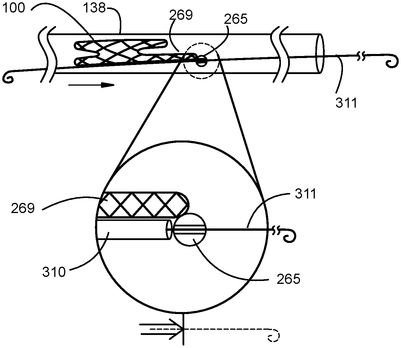
[0038] FIG. 1 is an illustration of a side or plan transparent view of a delivery catheter loaded with an orthogonal valve having a tension arm with a guidewire collar element and a guidewire extending through the guidewire collar with a guidewire sheath pushing against the guidewire collar element. Inset shows a non-limiting example of a guidewire collar attached to a tension arm with guidewire through the aperture of the guidewire collar and hypotube sheath stopped by the larger circumference of the guidewire collar, permitting pushing on the tension arm to pull the valve out of the delivery catheter.
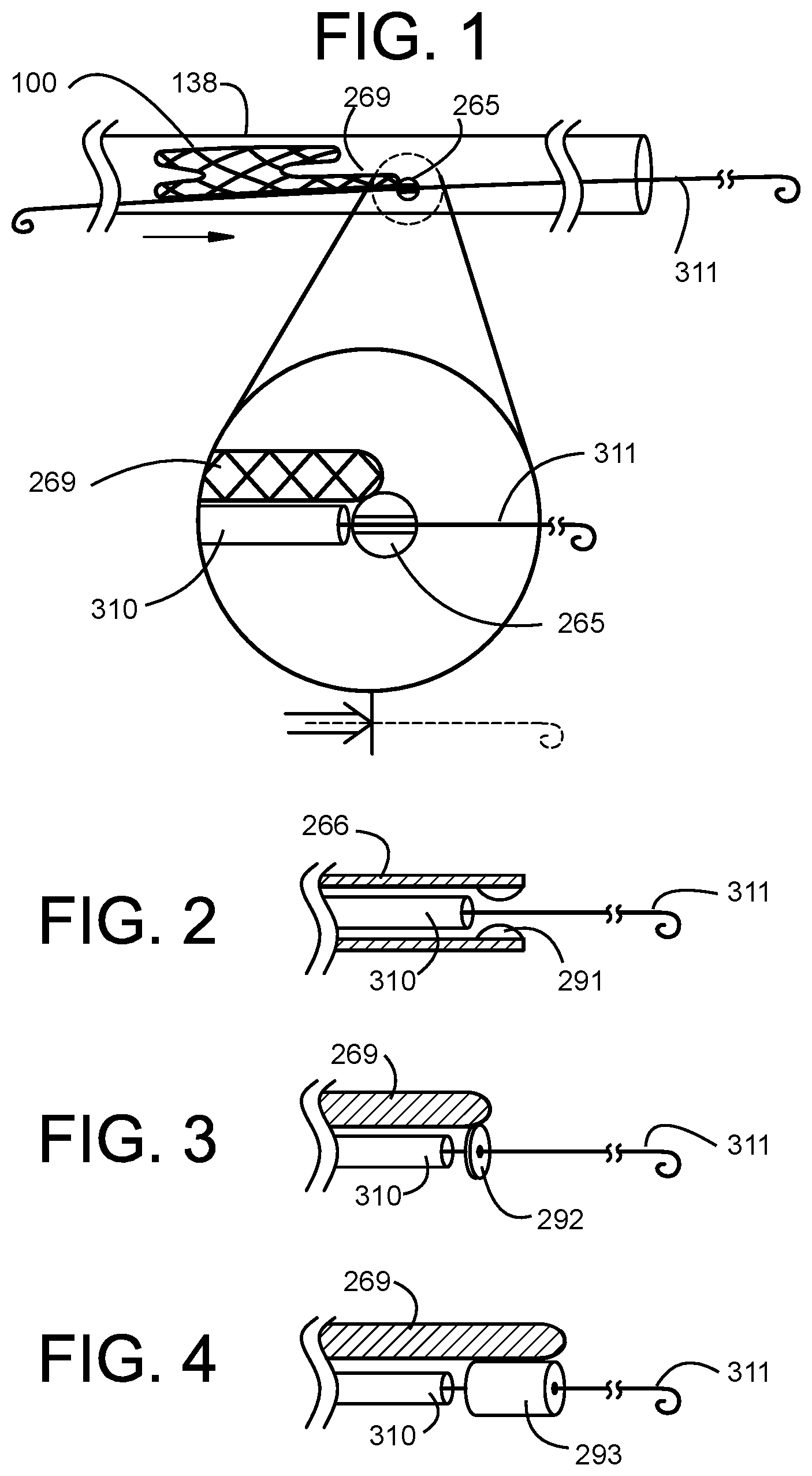
[0039] FIG. 2 is another non-limiting example of a guidewire collar attached to a tension arm with guidewire through the aperture of the guidewire collar and hypotube sheath stopped by the larger circumference of the guidewire collar, permitting pushing on the tension arm to pull the valve out of the delivery catheter.
[0040] FIG. 3 is another non-limiting example of a guidewire collar attached to a tension arm with guidewire through the aperture of the guidewire collar and hypotube sheath stopped by the larger circumference of the guidewire collar, permitting pushing on the tension arm to pull the valve out of the delivery catheter.
[0041] FIG. 4 is another non-limiting example of a guidewire collar attached to a tension arm with guidewire through the aperture of the guidewire collar and hypotube sheath stopped by the larger circumference of the guidewire collar, permitting pushing on the tension arm to pull the valve out of the delivery catheter.
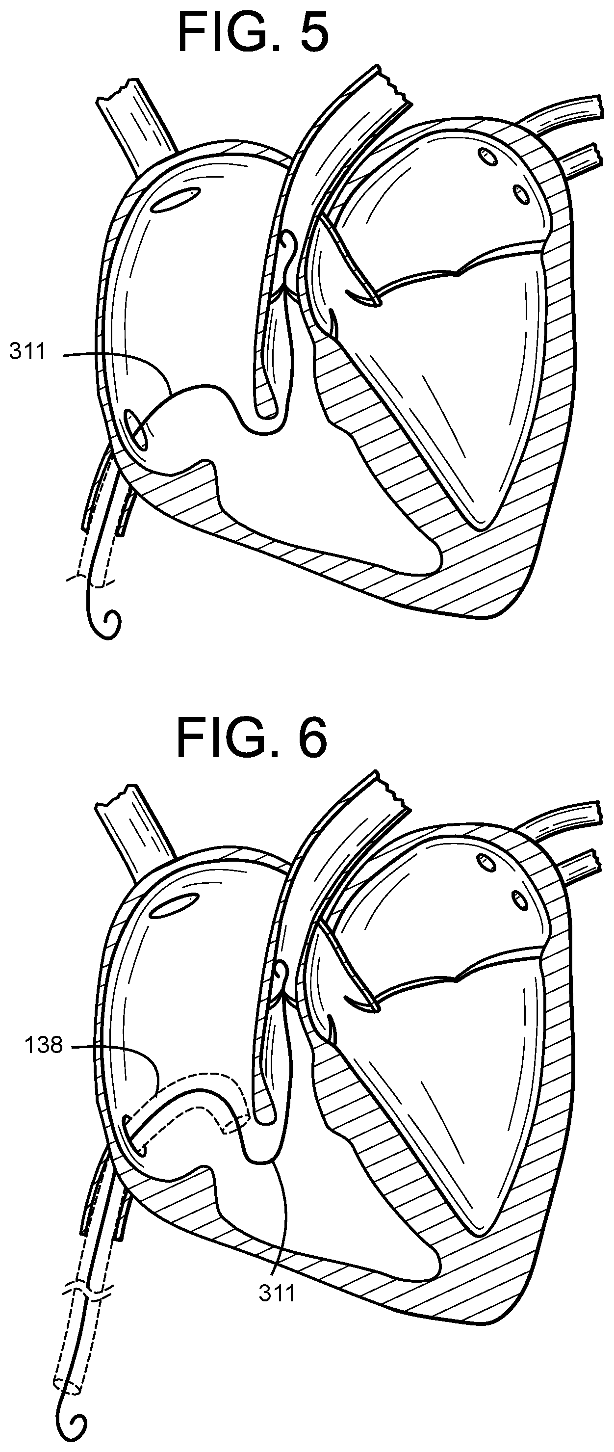
[0042] FIG. 5 is an illustration of step 1 of a 6-step process for delivery of an orthogonal prosthetic valve to the tricuspid annulus. FIG. 5 shows an 0.035 guidewire with hypotube sheath delivered to the right ventricular outflow tract (RVOT).
[0043] FIG. 6 is an illustration of step 2 of a 6-step process for delivery of an orthogonal prosthetic valve to the tricuspid annulus. FIG. 6 shows a 34 Fr delivery catheter being advanced over the guidewire to and through the native tricuspid annulus to the right ventricle.
[0044] FIG. 7 is an illustration of step 3 of a 6-step process for delivery of an orthogonal prosthetic valve to the tricuspid annulus. FIG. 7 shows a capsule having a compressed valve therein where the capsule is loaded into the proximal end of the delivery catheter and the valve is withdrawn from the capsule into the delivery catheter, with sheathed guidewire threaded through the valve and providing a wire path to the RVOT, planned deployment location.
[0045] FIG. 8 is an illustration of step 4 of a 6-step process for delivery of an orthogonal prosthetic valve to the tricuspid annulus. FIG. 8 shows the valve advanced up the catheter and deployed into the native annulus by pushing on the outer sheath of the guidewire to pull the valve up the catheter and into position. Tension arm is used to position the valve.
[0046] FIG. 9 is an illustration of step 5 of a 6-step process for delivery of an orthogonal prosthetic valve to the tricuspid annulus. FIG. 9 shows a catheter being used to push the proximal side of the valve into position within the annulus.
[0047] FIG. 10 is an illustration of step 6 of a 6-step process for delivery of an orthogonal prosthetic valve to the tricuspid annulus. FIG. 10 shows withdrawal of the delivery system and anchoring of the proximal side of the valve to the annular tissue.
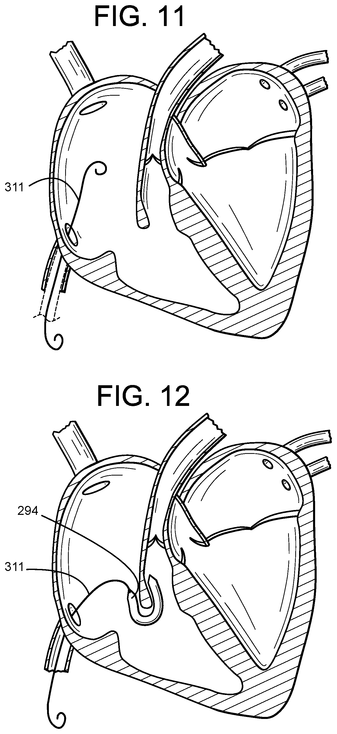
[0048] FIG. 11 is an illustration of step 1 of an 8-step process for delivery of an orthogonal prosthetic valve to the tricuspid annulus. FIG. 11 shows an 8 Fr guidewire advanced from the femoral through the inferior vena cava (IVC) to the right atrium.
[0049] FIG. 12 is an illustration of step 2 of an 8-step process for delivery of an orthogonal prosthetic valve to the tricuspid annulus. FIG. 12 shows a balloon catheter advanced over the guidewire through the native annulus and into the RVOT to expand and push aside valve and leaflet tissue, chordae tendinae that might tangle transcatheter delivery of the valve.
[0050] FIG. 13 is an illustration of step 3 of an 8-step process for delivery of an orthogonal prosthetic valve to the tricuspid annulus. FIG. 13 shows an 0.035 guidewire with hypotube sheath delivered to the right ventricular outflow tract (RVOT).
[0051] FIG. 14 is an illustration of step 4 of an 8-step process for delivery of an orthogonal prosthetic valve to the tricuspid annulus. FIG. 14 shows a 34 Fr delivery catheter being advanced over the guidewire to and through the native tricuspid annulus to the right ventricle.
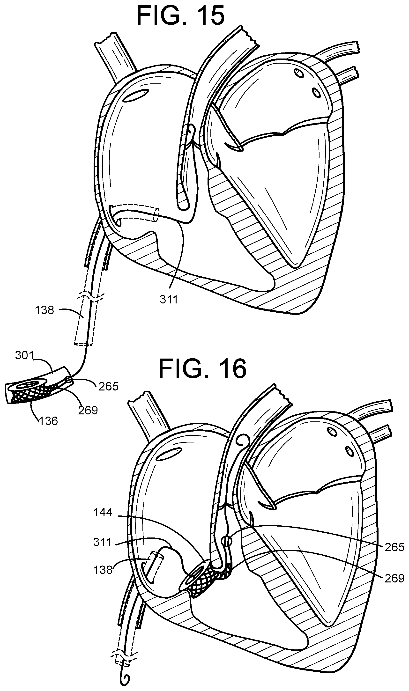
[0052] FIG. 15 is an illustration of step 5 of an 8-step process for delivery of an orthogonal prosthetic valve to the tricuspid annulus. FIG. 15 shows a capsule having a compressed valve therein where the capsule is loaded into the proximal end of the delivery catheter and the valve is withdrawn from the capsule into the delivery catheter, with sheathed guidewire threaded through the valve and providing a wire path to the RVOT, planned deployment location.
[0053] FIG. 16 is an illustration of step 6 of an 8-step process for delivery of an orthogonal prosthetic valve to the tricuspid annulus. FIG. 16 shows the valve advanced up the catheter and deployed into the native annulus by pushing on the outer sheath of the guidewire to pull the valve up the catheter and into position. Tension arm is used to position the valve.
[0054] FIG. 17 is an illustration of step 7 of an 8-step process for delivery of an orthogonal prosthetic valve to the tricuspid annulus. FIG. 17 shows a catheter being used to push the proximal side of the valve into position within the annulus.
[0055] FIG. 18 is an illustration of step 8 of an 8-step process for delivery of an orthogonal prosthetic valve to the tricuspid annulus. FIG. 18 shows withdrawal of the delivery system and anchoring of the proximal side of the valve to the annular tissue.
[0056] FIG. 19 is an illustration of step 1 of a 6-step process for delivery of an orthogonal prosthetic valve to the tricuspid annulus. FIG. 19 shows the valve advanced up the catheter and deployed into the native annulus.
[0057] FIG. 20 is an illustration of step 2 of a 6-step process for delivery of an orthogonal prosthetic valve to the tricuspid annulus. FIG. 20 shows pushing on the outer sheath of the guidewire to pull the valve up the catheter and into position, partially expelling the valve with tension arm into the RVOT and the distal side of the valve lodged against the annular wall.
[0058] FIG. 21 is an illustration of step 3 of a 6-step process for delivery of an orthogonal prosthetic valve to the tricuspid annulus. FIG. 21 shows a catheter being used to push the proximal side of the valve into position within the annulus.
[0059] FIG. 22 is an illustration of step 4 of a 6-step process for delivery of an orthogonal prosthetic valve to the tricuspid annulus. FIG. 22 shows how tension arm is used to position the valve while catheter being used to push the proximal side of the valve into position within the annulus.
[0060] FIG. 23 is an illustration of step 5 of a 6-step process for delivery of an orthogonal prosthetic valve to the tricuspid annulus. FIG. 23 shows how catheter delivers a tissue anchor to secure the proximal side of the valve to the annular tissue.
[0061] FIG. 24 is an illustration of step 6 of a 6-step process for delivery of an orthogonal prosthetic valve to the tricuspid annulus. FIG. 24 shows withdrawal of the delivery system and anchoring of the proximal side of the valve to the annular tissue.
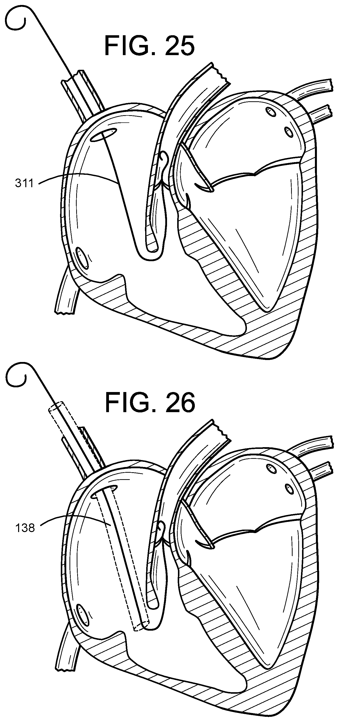
[0062] FIG. 25 is an illustration of step 1 of a 6-step process for delivery of a co-axial prosthetic valve to the tricuspid annulus. FIG. 25 shows an 0.035 guidewire with hypotube sheath delivered to the right ventricular outflow tract (RVOT) through the superior vena cava (SVC).
[0063] FIG. 26 is an illustration of step 2 of a 6-step process for delivery of a co-axial prosthetic valve to the tricuspid annulus.
[0064] FIG. 26 shows a 34 Fr delivery catheter being advanced over the guidewire to and through the native tricuspid annulus to the right ventricle.
[0065] FIG. 27 is an illustration of step 3 of a 6-step process for delivery of a co-axial prosthetic valve to the tricuspid annulus. FIG. 27 shows a capsule having a compressed valve therein where the capsule is loaded into the proximal end of the delivery catheter and the valve is withdrawn from the capsule into the delivery catheter, with sheathed guidewire threaded through the valve and providing a wire path to the RVOT, planned deployment location.
[0066] FIG. 28 is an illustration of step 4 of a 6-step process for delivery of a co-axial prosthetic valve to the tricuspid annulus. FIG. 28 shows the valve advanced up the catheter and deployed into the native annulus by pushing on the outer sheath of the guidewire to pull the valve up the catheter and into position. Tension arm is used to position the valve.
[0067] FIG. 29 is an illustration of step 5 of a 6-step process for delivery of a co-axial prosthetic valve to the tricuspid annulus. FIG. 29 shows a catheter being used to push the proximal side of the valve into position within the annulus.
[0068] FIG. 30 is an illustration of step 6 of a 6-step process for delivery of a co-axial prosthetic valve to the tricuspid annulus. FIG. 30 shows withdrawal of the delivery system and anchoring of the proximal side of the valve to the annular tissue.
[0069] FIG. 31 is an illustration of step 1 of a 4-step process for delivery of a co-axial prosthetic valve to the tricuspid annulus. FIG. 31 shows a co-axial valve being loaded into the distal end of the delivery catheter, with the sheathed guidewire threaded through the tension arm and guidewire collar.
[0070] FIG. 32 is an illustration of step 2 of a 4-step process for delivery of a co-axial prosthetic valve to the tricuspid annulus. FIG. 32 shows a co-axial valve being delivered to the proximal end of the delivery catheter, with the sheathed guidewire threaded through the tension arm and guidewire collar.
[0071] FIG. 33 is an illustration of step 3 of a 4-step process for delivery of a co-axial prosthetic valve to the tricuspid annulus. FIG. 33 shows a co-axial valve partially expelled from the delivery catheter, with the the tension arm and guidewire collar being positioned into the RVOT.
[0072] FIG. 34 is an illustration of step 4 of a 4-step process for delivery of a co-axial prosthetic valve to the tricuspid annulus. FIG. 34 shows that, once positioned, the self-expanding the valve can be completely expelled from the delivery catheter and deployed as a prosthetic valve.
[0073] FIG. 35 is an illustration of step 1 of a 7-step process for delivery of a co-axial prosthetic valve to the tricuspid annulus. FIG. 35 shows an 0.035 guidewire with hypotube sheath delivered to the right ventricular outflow tract (RVOT) through the superior vena cava (SVC).
[0074] FIG. 36 is an illustration of step 2 of a 7-step process for delivery of a co-axial prosthetic valve to the tricuspid annulus. FIG. 36 shows a 34 Fr delivery catheter being advanced over the guidewire to and through the native tricuspid annulus to the right ventricle.
[0075] FIG. 37 is an illustration of step 3 of a 7-step process for delivery of a co-axial prosthetic valve to the tricuspid annulus. FIG. 37 shows a capsule having a compressed valve therein where the capsule is loaded into the proximal end of the delivery catheter and the valve is withdrawn from the capsule into the delivery catheter, with sheathed guidewire threaded through the valve and providing a wire path to the RVOT, planned deployment location.
[0076] FIG. 38 is an illustration of step 4 of a 7-step process for delivery of a co-axial prosthetic valve to the tricuspid annulus. FIG. 38 shows the valve advanced up the catheter and deployed into the native annulus by pushing on the outer sheath of the guidewire to pull the valve up the catheter and into position. Tension arm is used to position the valve.
[0077] FIG. 39 is an illustration of step 5 of a 7-step process for delivery of a co-axial prosthetic valve to the tricuspid annulus. FIG. 39 shows a catheter being used to push the proximal side of the valve into position within the annulus.
[0078] FIG. 40 is an illustration of step 6 of a 7-step process for delivery of a co-axial prosthetic valve to the tricuspid annulus. FIG. 40 shows balloon expansion of the co-axial valve in the native annulus and anchoring of the proximal side of the valve to the annular tissue.
[0079] FIG. 41 is an illustration of step 7 of a 7-step process for delivery of a co-axial prosthetic valve to the tricuspid annulus. FIG. 41 shows withdrawal of the delivery system and anchoring of the proximal side of the valve to the annular tissue.
[0080] FIG. 42 is an illustration of step 1 of a 6-step process for delivery of a co-axial prosthetic valve to the tricuspid annulus. FIG. 42 shows the delivery catheter deployed to the native annulus.
[0081] FIG. 43 is an illustration of step 2 of a 6-step process for delivery of a co-axial prosthetic valve to the tricuspid annulus. FIG. 43 shows a co-axial valve being loaded into the delivery catheter, with the sheathed guidewire threaded through the tension arm and guidewire collar.
[0082] FIG. 44 is an illustration of step 3 of a 6-step process for delivery of a co-axial prosthetic valve to the tricuspid annulus. FIG. 44 shows a co-axial valve being delivered to the proximal end of the delivery catheter, with the sheathed guidewire threaded through the tension arm and guidewire collar.
[0083] FIG. 45 is an illustration of step 4 of a 6-step process for delivery of a co-axial prosthetic valve to the tricuspid annulus. FIG. 45 shows a co-axial valve partially expelled from the delivery catheter, with the the tension arm and guidewire collar being positioned into the RVOT.
[0084] FIG. 46 is an illustration of step 5 of a 6-step process for delivery of a co-axial prosthetic valve to the tricuspid annulus. FIG. 46 shows that, once positioned, the balloon-expanding co-axial valve can be completely deployed into the inner circumference of the native annulus to function as a prosthetic valve.
[0085] FIG. 47 is an illustration of step 6 of a 6-step process for delivery of a co-axial prosthetic valve to the tricuspid annulus. FIG. 47 shows the deployed valve.
DETAILED DESCRIPTION OF THE PREFERRED EMBODIMENTS
[0086] The invention is directed to a transcatheter heart valve replacement that is a low profile, orthogonally delivered implantable prosthetic valve having an ring-shaped tubular frame, an inner 2- or 3-panel sleeve, an elongated sub-annular tension arm extending into the right ventricular outflow tract, and one or more anchor elements.
[0087] The embodiments herein and the various features and advantageous details thereof are explained more fully with reference to the non-limiting embodiments that are illustrated in the accompanying drawings and detailed in the following description. Descriptions of well-known components and processing techniques are omitted so as to not unnecessarily obscure the embodiments herein. The examples used herein are intended merely to facilitate an understanding of ways in which the embodiments herein may be practiced and to further enable those of skill in the art to practice the embodiments herein. Accordingly, the examples should not be construed as limiting the scope of the embodiments herein.
[0088] Rather, these embodiments are provided so that this disclosure will be thorough and complete, and will fully convey the scope of the invention to those skilled in the art. Like numbers refer to like elements throughout. As used herein the term "and/or" includes any and all combinations of one or more of the associated listed items.
[0089] The terminology used herein is for the purpose of describing particular embodiments only and is not intended to limit the full scope of the invention. As used herein, the singular forms "a", "an" and "the" are intended to include the plural forms as well, unless the context clearly indicates otherwise. It will be further understood that the terms "comprises" and/or "comprising," when used in this specification, specify the presence of stated features, integers, steps, operations, elements, and/or components, but do not preclude the presence or addition of one or more other features, integers, steps, operations, elements, components, and/or groups thereof.
[0090] Unless defined otherwise, all technical and scientific terms used herein have the same meanings as commonly understood by one of ordinary skill in the art. Nothing in this disclosure is to be construed as an admission that the embodiments described in this disclosure are not entitled to antedate such disclosure by virtue of prior invention. As used in this document, the term "comprising" means "including, but not limited to."
[0091] Many modifications and variations can be made without departing from its spirit and scope, as will be apparent to those skilled in the art. Functionally equivalent methods and apparatuses within the scope of the disclosure, in addition to those enumerated herein, will be apparent to those skilled in the art from the foregoing descriptions. Such modifications and variations are intended to fall within the scope of the appended claims. The present disclosure is to be limited only by the terms of the appended claims, along with the full scope of equivalents to which such claims are entitled. It is to be understood that this disclosure is not limited to particular methods, reagents, compounds, compositions or biological systems, which can, of course, vary. It is also to be understood that the terminology used herein is for the purpose of describing particular embodiments only, and is not intended to be limiting.
[0092] With respect to the use of substantially any plural and/or singular terms herein, those having skill in the art can translate from the plural to the singular and/or from the singular to the plural as is appropriate to the context and/or application. The various singular/plural permutations may be expressly set forth herein for sake of clarity.
[0093] It will be understood by those within the art that, in general, terms used herein, and especially in the appended claims (e.g., bodies of the appended claims) are generally intended as "open" terms (e.g., the term "including" should be interpreted as "including but not limited to," the term "having" should be interpreted as "having at least," the term "includes" should be interpreted as "includes but is not limited to," etc.). It will be further understood by those within the art that virtually any disjunctive word and/or phrase presenting two or more alternative terms, whether in the description, claims, or drawings, should be understood to contemplate the possibilities of including one of the terms, either of the terms, or both terms. For example, the phrase "A or B" will be understood to include the possibilities of "A" or "B" or "A and B."
[0094] In addition, where features or aspects of the disclosure are described in terms of Markush groups, those skilled in the art will recognize that the disclosure is also thereby described in terms of any individual member or subgroup of members of the Markush group.
[0095] As will be understood by one skilled in the art, for any and all purposes, such as in terms of providing a written description, all ranges disclosed herein also encompass any and all possible subranges and combinations of subranges thereof. Any listed range can be easily recognized as sufficiently describing and enabling the same range being broken down into at least equal subparts. As will be understood by one skilled in the art, a range includes each individual member.
Definitions
[0096] Side-Delivery or Orthogonal Delivery
[0097] In the description and claims herein, the terms "side-delivered", "side-delivery", "orthogonal", "orthogonally delivered" and so forth are used to describe that the valves of the present invention are compressed and delivered at a roughly 90 degree angle compared to traditional transcatheter heart valves. Orthogonal delivery is a transverse delivery where a perimeter distal sidewall exits the delivery catheter first, followed by the central aperture, followed by the proximal sidewall.
[0098] Traditional valves have a central cylinder axis that is parallel to the length-wise axis of the delivery catheter and are deployed from the end of the delivery catheter and expanded radially outward from the central annular axis, in a manner akin to pushing a closed spring-loaded umbrella out of a sleeve to make it spring open. However, the valves of the present invention are compressed and delivered in a sideways manner. To begin with the shape of the expanded valve is that of a large diameter shortened cylinder with an extended collar or cuff. The valves are compressed, in one preferred embodiment, where the central axis of the valve is roughly perpendicular to (orthogonal to) the length-wise axis of the delivery catheter. In one preferred embodiment, the valves are compressed vertically, similar to collapsing the height of a cylinder accordion-style from taller to shorter, and the valves are also compressed by folding a front panel against a back panel. In another preferred embodiment, the valves may be compressed by rolling.
[0099] Traditional valves can only be expanded as large as what the internal diameter of the delivery catheter will allow. Efforts to increase the expanded diameter of traditional valves have run into the problems of trying to compress too much material and structure into too little space.
[0100] Mathematically, the term orthogonal refers to an intersecting angle of 90 degrees between two lines or planes. As used, herein the term "substantially orthogonal" refers to an intersecting angle ranging from 75 to 105 degrees. The intersecting angle or orthogonal angle refers to both (i) the relationship between the length-wise cylindrical axis of the delivery catheter and the long-axis of the compressed valve of the invention, where the long-axis is perpendicular to the central cylinder axis of traditional valves, and (ii) the relationship between the long-axis of the compressed or expanded valve of the invention and the axis defined by the blood flow through the prosthetic heart valve where the blood is flowing, eg. from one part of the body or chamber of the heart to another downstream part of the body or chamber of the heart, such as from an atrium to a ventricle through a native annulus.
[0101] Transcatheter
[0102] In the description and claims herein, the term "transcatheter" is used to define the process of accessing, controlling, and delivering a medical device or instrument within the lumen of a catheter that is deployed into a heart chamber, as well as an item that has been delivered or controlled by such as process. Transcatheter access is known to include via femoral artery and femoral vein, via brachial artery and vein, via carotid and jugular, via intercostal (rib) space, and via sub-xyphoid. Transcatheter can be synonymous with transluminal and is functionally related to the term "percutaneous" as it relates to delivery of heart valves.
[0103] In one preferred embodiment of the invention, the transcatheter approach includes advancing to the tricuspid valve/right atrium of the heart through the inferior vena cava via the femoral vein, (ii) advancing to the tricuspid valve/right atrium of the heart through the superior vena cava via the jugular vein, (iii) advancing to the tricuspid valve/right atrium of the heart through a trans-atrial approach, e.g. fossa ovalis or lower.
[0104] In another preferred embodiment of the invention, the transcatheter approach includes (i) advancing to the mitral valve or pulmonary artery of the heart through the inferior vena cava via the femoral vein, (ii) advancing to the mitral valve or pulmonary artery of the heart through the superior vena cava via the jugular vein, (iii) advancing to the mitral valve of the heart through a trans-atrial approach, e.g. fossa ovalis or lower, via the IVC-femoral or the SVC-jugular approach.
[0105] Annular Support Frame
[0106] In the description and claims herein, the term "annular support frame", and also "wire frame" or "flange or "collar" refers to a three-dimensional structural component that is seated within a native valve annulus and is used as a mounting element for a leaflet structure, a flow control component, or a flexible reciprocating valve.
[0107] In a preferred embodiment, the annular support frame is a self-expanding annular support frame, having a central channel and an outer perimeter wall circumscribing a central vertical axis in an expanded configuration. The perimeter wall encompasses both the collar and the lower body portions.
[0108] The perimeter wall can be further defined as having a front wall portion and a back wall portion, which are connected along a near side (to the IVC) or proximal side to a proximal fold area, and connected along a far or distal side to a distal fold area.
[0109] This front wall portion can be further defined as having a front upper collar portion and a front lower body portion, and the the back wall portion can be further defined as having a back upper collar portion and a back lower body portion.
[0110] The annular (outer) support frame has a flow control component mounted within the annular support frame and configured to permit blood flow in a first direction through an inflow end of the valve and block blood flow in a second direction, opposite the first direction, through an outflow end of the valve.
[0111] Since the outer frame is preferably made of superelastic metal or alloy such as Nitinol, the frame is compressible. Preferably, the outer frame is constructed of a plurality of compressible wire cells having a orientation and cell geometry substantially orthogonal to the central vertical axis to minimize wire cell strain when the annular support frame when configured in a vertical compressed configuration, a rolled compressed configuration, or a folded compressed configuration.
[0112] Annular Support Frame Structure
[0113] The annular support frame can be a ring, or cylindrical or conical tube, made from a durable, biocompatible structural material such as Nitinol or similar alloy, wherein the annular support frame is formed by manufacturing the structural material as a braided wire frame, a laser-cut wire frame, or a wire loop. The annular support frame is about 5-60 mm in height, has an outer diameter dimension, R, of 30-80 mm, and an inner diameter dimension of 31-79 mm, accounting for the thickness of the wire material itself. As stated, the annular support frame can have a side-profile of a ring shape, cylinder shape, conical tube shape, but may also have a side profile of a flat-cone shape, an inverted flat-cone shape (narrower at top, wider at bottom), a concave cylinder (walls bent in), a convex cylinder (walls bulging out), an angular hourglass, a curved, graduated hourglass, a ring or cylinder having a flared top, flared bottom, or both. In one preferred embodiment, the annular support frame used in the prosthetic heart valve deployed in the mitral annulus may have a complex shape determined by the anatomical structures where the valve is being mounted. For example, in the mitral annulus, the circumference of the mitral valve may be a rounded ellipse, the septal wall is known to be substantially vertical, and the mitral is known to enlarge in disease states. Accordingly, a prosthetic heart valve may start in a roughly tubular configuration, and be heat-shaped to provide an upper atrial cuff or flange for atrial sealing and a lower trans-annular tubular or cylindrical section having an hourglass cross-section for about 60-80% of the circumference to conform to the native annulus along the posterior and anterior annular segments while remaining substantially vertically flat along 20-40% of the annular circumference to conform to the septal annular segment.
[0114] Annular Support Frame Covering
[0115] The annular support frame is optionally internally or externally covered, partially or completely, with a biocompatible material such as pericardium. The annular support frame may also be optionally externally covered, partially or completely, with a second biocompatible material such as polyester or Dacron.RTM..
[0116] Annular Support Frame Purpose
[0117] The annular support frame has a central axial lumen where a prosthetic heart valve or flow-control structure, such as a reciprocating compressible sleeve, is mounted across the diameter of the lumen. The annular support frame is also tensioned against the inner aspect of the native annulus and provides structural patency to a weakened annular ring.
[0118] Valve Frame Optional Atrial Sealing Collars
[0119] The valve frame may optionally have a separate atrial sealing collar attached to the upper (atrial) edge of the frame, for deploying on the atrial floor, that is used to direct blood from the atrium into the sleeve and to seal against blood leakage around the valve frame. The valve frame may also optionally have a separate ventricular sealing collar attached to the lower (ventricular) edge of the frame, for deploying in the ventricle immediately below the native annulus that is used to prevent regurgitant leakage during systole, to prevent dislodging of the device during systole, to sandwich or compress the native annulus or adjacent tissue against the atrial sealing collar, and optionally to attach to and support the sleeve/conduit.
[0120] Annular Support Frame Delivery
[0121] The valve frame/annular support frame may be compressed for transcatheter delivery and may be expandable as a self-expandable shape-memory element or using a transcatheter expansion balloon. Some embodiments may have both an atrial sealing collar and a ventricular sealing collar, whereas other embodiments within the scope of the invention include prosthetic valves having either a single atrial sealing collar, a single ventricular sealing collar, or having no additional sealing collar structure.
[0122] Frame Material
[0123] Preferably, the frame is made from a superelastic metal component, such as laser-cut Nitinol tube, or flat sheet or other similarly functioning material such as braided wire. The material may be used for the frame/stent, for the collar, and/or for anchors. It is contemplated as within the scope of the invention to use other shape memory alloys, as well as polymer composites including composites containing carbon nanotubes, carbon fibers, metal fibers, glass fibers, and polymer fibers. It is contemplated that the frame may be constructed as a braid, wire, or laser cut frame. Laser cut frames are preferably made from Nitinol, but also without limitation made from stainless steel, cobalt chromium, titanium, and other functionally equivalent metals and alloys.
[0124] One key aspect of the frame design is that it be compressible and when released have the stated property that it returns to its original (uncompressed) shape. This requirement limits the potential material selections to metals and plastics that have shape memory properties. With regards to metals, Nitinol has been found to be especially useful since it can be processed to be austenitic, martensitic or super elastic. Martensitic and super elastic alloys can be processed to demonstrate the required mechanical behavior.
[0125] Laser Cut
[0126] One possible construction of the wire frame envisions the laser cutting of a thin, isodiametric Nitinol tube. The laser cuts form regular cutouts in the thin Nitinol tube. In one preferred embodiment, the Nitinol tube expands to form a three-dimensional structure formed from diamond-shaped cells. The structure may also have additional functional elements, e.g. loops, anchors, etc. for attaching accessory components such as biocompatible covers, tissue anchors, releasable deployment and retrieval control guides, knobs, attachments, rigging, and so forth.
[0127] Secondarily the tube is thermo-mechanically processed using industry standard Nitinol shape forming methods. The treatment of the wire frame in this manner will form a device that has shape memory properties and will readily revert to the memory shape once deployed.
[0128] Braided Wire
[0129] Another possible construction of the wire frame envisions utilizing simple braiding techniques using a Nitinol wire and a simple braiding fixture. The wire is wound on the braiding fixture in a pattern until an isodiametric tube is formed. Secondarily, the braided wire frame is placed on a shaping fixture and processed using industry standard Nitinol shape forming methods.
[0130] Flow Control Component
[0131] In the description and claims herein, the term "flow control component" refers in a non-limiting sense to a leaflet structure having 2-, 3-, 4-leaflets of flexible biocompatible material such a treated or untreated pericardium that is sewn or joined to a tubular frame, to function as a prosthetic valve. Such a valve can be a heart valve, such as a tricuspid, mitral, aortic, or pulmonary, that is open to blood flowing during diastole from atrium to ventricle, and that closes from systolic ventricular pressure applied to the outer surface. Repeated opening and closing in sequence can be described as "reciprocating".
[0132] Tissue Anchor
[0133] In the description and claims herein, the term "tissue anchor" or "plication tissue anchor" or "secondary tissue anchor", or "dart" or "pin" refers to a fastening device that connects the upper atrial frame to the the native annular tissue, usually at or near the periphery of the atrial sealing collar. The anchor may be positioned to avoid piercing tissue and just rely on the compressive force of the two plate-like sealing collars on the captured tissue, or the anchor, itself or with an integrated securement wire, may pierce through native tissue to provide anchoring, or a combination of both. The anchor may have a specialized securement mechanism, such as a pointed tip with a groove and flanged shoulder that is inserted or popped into a mated aperture or an array of mated apertures that allow the anchor to attach, but prevent detachment when the aperture periphery locks into the groove near the flanged shoulder. The securement wire may be attached or anchored to the sealing collar opposite the pin by any attachment or anchoring mechanisms, including a knot, a suture, a wire crimp, a wire lock having a cam mechanism, or combinations.
[0134] Support Post
[0135] The term "support post" refers to a rigid or semi-rigid length of material such as Nitinol or PEEK, that may be mounted on a spoked frame and that runs axially, or down the center of, or within a sewn seam of -, the flexible sleeve. The sleeve may be unattached to the support post, or the sleeve may be directly or indirectly attached to the support post.
[0136] In the description that follows, the term "body channel" is used to define a blood conduit or vessel within the body. Of course, the particular application of the prosthetic heart valve determines the body channel at issue. An aortic valve replacement, for example, would be implanted in, or adjacent to, the aortic annulus. Likewise, a tricuspid or mitral valve replacement will be implanted at the tricuspid or mitral annulus. Certain features of the present invention are particularly advantageous for one implantation site or the other. However, unless the combination is structurally impossible, or excluded by claim language, any of the heart valve embodiments described herein could be implanted in any body channel.
[0137] The term "lumen" refers to the inside of the cylinder tube. The term "bore" refers to the inner diameter.
[0138] Displacement--The volume of fluid displaced by one complete stroke or revolution
[0139] Ejection fraction is a measurement of the percentage of blood leaving your heart each time it contracts. During each heartbeat pumping cycle, the heart contracts and relaxes. When your heart contracts, it ejects blood from the two pumping chambers (ventricles)
[0140] As a point of further definition, the term "expandable" is used herein to refer to a component of the heart valve capable of expanding from a first, delivery diameter to a second, implantation diameter. An expandable structure, therefore, does not mean one that might undergo slight expansion from a rise in temperature, or other such incidental cause. Conversely, "non-expandable" should not be interpreted to mean completely rigid or a dimensionally stable, as some slight expansion of conventional "non-expandable" heart valves, for example, may be observed.
[0141] Force--A push or pull acting upon a body. In a hydraulic cylinder, it is the product of the pressure on the fluid, multiplied by the effective area of the cylinder piston.
[0142] Prosthetic Valve
[0143] The term "valve prosthesis" or "prosthetic valve" refers to a combination of a frame and a leaflet or flow control structure, and encompasses both complete replacement of an anatomical part, e.g. a new mechanical valve replaces a native valve, as well as medical devices that take the place of and/or assist, repair, or improve existing anatomical parts, e.g. native valve is left in place. For mounting within a passive assist cage, the invention contemplates a wide variety of (bio)prosthetic artificial heart valves. Contemplated as within the scope of the invention are ball valves (e.g. Starr-Edwards), bileaflet valves (St. Jude), tilting disc valves (e.g. Bjork-Shiley), stented pericardium heart-valve prosthesis' (bovine, porcine, ovine) (Edwards line of bioprostheses, St. Jude prosthetic valves), as well as homograft and autograft valves. For bioprosthetic pericardial valves, it is contemplated to use bioprosthetic aortic valves, bioprosthetic mitral valves, bioprosthetic tricuspid valves, and bioprosthetic pulmonary valves.
[0144] Tethers
[0145] The tethers are made from surgical-grade materials such as biocompatible polymer suture material. Non-limiting examples of such material include ultra high-molecular weight polyethylene (UHMWPE), 2-0 exPFTE(polytetrafluoroethylene) or 2-0 polypropylene. In one embodiment the tethers are inelastic. It is also contemplated that one or more of the tethers may optionally be elastic to provide an even further degree of compliance of the valve during the cardiac cycle.
[0146] Tines-Anchors-Tines/Barbs
[0147] The device can be seated within the valvular annulus through the use of tines or barbs. These may be used in conjunction with, or in place of one or more tethers. The tines or barbs are located to provide attachment to adjacent tissue. Tines are forced into the annular tissue by mechanical means such as using a balloon catheter. In one non-limiting embodiment, the tines may optionally be semi-circular hooks that upon expansion of the wire frame body, pierce, rotate into, and hold annular tissue securely. Anchors are deployed by over-wire delivery of an anchor or anchors through a delivery catheter. The catheter may have multiple axial lumens for delivery of a variety of anchoring tools, including anchor setting tools, force application tools, hooks, snaring tools, cutting tools, radio-frequency and radiological visualization tools and markers, and suture/thread manipulation tools. Once the anchor(s) are attached to the moderator band, tensioning tools may be used to adjust the length of tethers that connect to an implanted valve to adjust and secure the implant as necessary for proper functioning. It is also contemplated that anchors may be spring-loaded and may have tether-attachment or tether-capture mechanisms built into the tethering face of the anchor(s). Anchors may also have in-growth material, such as polyester fibers, to promote in-growth of the anchors into the myocardium.
[0148] In one embodiment, a prosthetic valve frame may include an atrial sealing collar, a ventricular sealing collar, or both.
[0149] Tube and/or Cover Material--Biological Tissue
[0150] The tissue used herein is a biological tissue that is a chemically stabilized pericardial tissue of an animal, such as a cow (bovine pericardium) or sheep (ovine pericardium) or pig (porcine pericardium) or horse (equine pericardium). Preferably, the tissue is bovine pericardial tissue. Examples of suitable tissue include that used in the products Duraguard.RTM., Peri-Guard.RTM., and Vascu-Guard.RTM., all products currently used in surgical procedures, and which are marketed as being harvested generally from cattle less than 30 months old. Other patents and publications disclose the surgical use of harvested, biocompatible animal thin tissues suitable herein as biocompatible "jackets" or sleeves for implantable stents, including for example, U.S. Pat. No. 5,554,185 to Block, U.S. Pat. No. 7,108,717 to Design & Performance-Cyprus Limited disclosing a covered stent assembly, U.S. Pat. No. 6,440,164 to Scimed Life Systems, Inc. disclosing a bioprosthetic valve for implantation, and U.S. Pat. No. 5,336,616 to LifeCell Corporation discloses acellular collagen-based tissue matrix for transplantation.
[0151] Polymers
[0152] In one preferred embodiment, the conduit may optionally be made from a synthetic material such a polyurethane or polytetrafluoroethylene.
[0153] Where a thin, durable synthetic material is contemplated, e.g. for a covering, synthetic polymer materials such expanded polytetrafluoroethylene or polyester may optionally be used. Other suitable materials may optionally include thermoplastic polycarbonate urethane, polyether urethane, segmented polyether urethane, silicone polyether urethane, silicone-polycarbonate urethane, and ultra-high molecular weight polyethylene. Additional biocompatible polymers may optionally include polyolefins, elastomers, polyethylene-glycols, polyethersulphones, polysulphones, polyvinylpyrrolidones, polyvinylchlorides, other fluoropolymers, silicone polyesters, siloxane polymers and/or oligomers, and/or polylactones, and block co-polymers using the same.
[0154] Polyamides (PA)
[0155] PA is an early engineering thermoplastic invented that consists of a "super polyester" fiber with molecular weight greater than 10,000. It is commonly called Nylon. Application of polyamides includes transparent tubing's for cardiovascular applications, hemodialysis membranes, and also production of percutaneous transluminal coronary angioplasty (PTCA) catheters.
[0156] Polyolefin
[0157] Polyolefins include polyethylene and polypropylene are the two important polymers of polyolefins and have better biocompatibility and chemical resistance. In cardiovascular uses, both low-density polyethylene and high-density polyethylene are utilized in making tubing and housings. Polypropylene is used for making heart valve structures.
[0158] Polyesters
[0159] Polyesters includes polyethylene-terephthalate (PET), using the name Dacron. It is typically used as knitted or woven fabric for vascular grafts. Woven PET has smaller pores which reduces blood leakage and better efficiency as vascular grafts compared with the knitted one. PET grafts are also available with a protein coating (collagen or albumin) for reducing blood loss and better biocompatibility [39]. PET vascular grafts with endothelial cells have been searched as a means for improving patency rates. Moreover, polyesters are widely preferred material for the manufacturing of bioabsorbable stents. Poly-L-lactic acids (PLLA), polyglycolic acid (PGA), and poly(D, L-lactide/glycolide) copolymer (PDLA) are some of the commonly used bioabsorbable polymers.
[0160] Polytetrafluoroethylene
[0161] Polytetrafluoroethylene (PTFE) is synthetic fluorocarbon polymer with the common commercial name of Teflon by Dupont Co. Common applications of PTFE in cardiovascular engineering include vascular grafts and heart valves. PTFE sutures are used in the repair of mitral valve for myxomatous disease and also in surgery for prolapse of the anterior or posterior leaflets of mitral valves. PTFE is particularly used in implantable prosthetic heart valve rings. It has been successfully used as vascular grafts when the devices are implanted in high-flow, large-diameter arteries such as the aorta. Problem occurs when it is implanted below aortic bifurcations and another form of PTFE called elongated-PTFE (e-PTFE) was explored. Expanded PTFE is formed by compression of PTFE in the presence of career medium and finally extruding the mixture. Extrudate formed by this process is then heated to near its glass transition temperature and stretched to obtain microscopically porous PTFE known as e-PTFE. This form of PTFE was indicated for use in smaller arteries with lower flow rates promoting low thrombogenicity, lower rates of restenosis and hemostasis, less calcification, and biochemically inert properties.
[0162] Polyurethanes
[0163] Polyurethane has good physiochemical and mechanical properties and is highly biocompatible which allows unrestricted usage in blood contacting devices. It has high shear strength, elasticity, and transparency. Moreover, the surface of polyurethane has good resistance for microbes and the thrombosis formation by PU is almost similar to the versatile cardiovascular biomaterial like PTFE. Conventionally, segmented polyurethanes (SPUs) have been used for various cardiovascular applications such as valve structures, pacemaker leads and ventricular assisting device.
[0164] Covered Wire Frame Materials
[0165] Drug-eluting wire frames are contemplated for use herein. DES basically consist of three parts: wire frame platform, coating, and drug. Some of the examples for polymer free DES are Amazon Pax (MINVASYS) using Amazonia CroCo (L605) cobalt chromium (Co--Cr) wire frame with Paclitaxel as an antiproliferative agent and abluminal coating have been utilized as the carrier of the drug. BioFreedom (Biosensors Inc.) using stainless steel as base with modified abluminal coating as carrier surface for the antiproliferative drug Biolimus A9. Optima (CID S.r.I.) using 316 L stainless steel wire frame as base for the drug Tacrolimus and utilizing integrated turbostratic carbofilm as the drug carrier. VESTA sync (MIV Therapeutics) using GenX stainless steel (316 L) as base utilizing microporous hydroxyapatite coating as carrier for the drug Sirolimus. YUKON choice (Translumina) used 316 L stainless steel as base for the drugs Sirolimus in combination with Probucol.
[0166] Biosorbable polymers may also be used herein as a carrier matrix for drugs. Cypher, Taxus, and Endeavour are the three basic type of bioabsorbable DES. Cypher (J&J, Cordis) uses a 316 L stainless steel coated with polyethylene vinyl acetate (PEVA) and poly-butyl methacrylate (PBMA) for carrying the drug Sirolimus. Taxus (Boston Scientific) utilizes 316 L stainless steel wire frames coated with translute Styrene Isoprene Butadiene (SIBS) copolymer for carrying Paclitaxel which elutes over a period of about 90 days. Endeavour (Medtronic) uses a cobalt chrome driver wire frame for carrying zotarolimus with phosphorylcholine as drug carrier. BioMatrix employing S-Wire frame (316 L) stainless steel as base with polylactic acid surface for carrying the antiproliferative drug Biolimus. ELIXIR-DES program (Elixir Medical Corp) consisting both polyester and polylactide coated wire frames for carrying the drug novolimus with cobalt-chromium (Co--Cr) as base. JACTAX (Boston Scientific Corp.) utilized D-lactic polylactic acid (DLPLA) coated (316 L) stainless steel wire frames for carrying Paclitaxel. NEVO (Cordis Corporation, Johnson & Johnson) used cobalt chromium (Co--Cr) wire frame coated with polylactic-co-glycolic acid (PLGA) for carrying the drug Sirolimus.
DRAWING FIGURES
[0167] Referring now to the FIGURES, FIG. 1 is an illustration of a side or plan transparent view of a delivery catheter 138 loaded with a side-delivered (orthogonal) valve 100 having a tension arm 269 with a guidewire collar element 265 and a guidewire 311 extending through the guidewire collar 265 with a guidewire sheath 310 pushing against the guidewire collar element 265. Inset shows a non-limiting example of a guidewire collar 265 attached to a tension arm 269 with guidewire 311 through the aperture of the guidewire collar 265 and hypotube sheath 310 stopped by the larger circumference of the guidewire collar 265, permitting pushing on the tension arm 269 to pull the valve 100 out of the delivery catheter 138.
[0168] FIG. 2 is another non-limiting example of a guidewire collar 291 attached to a tension arm 269 with guidewire 311 through the aperture of the guidewire collar 291 and hypotube sheath 310 stopped by the larger circumference of the guidewire collar 291, permitting pushing on the tension arm 269 to pull the valve out of the delivery catheter 138.
[0169] FIG. 3 is another non-limiting example of a guidewire collar 292 attached to a tension arm 269 with guidewire 311 through the aperture of the guidewire collar 292 and hypotube sheath 310 stopped, as it slides over the guidewire--the guidewire is in lumen of hypotube sheath--by the larger circumference of the guidewire collar 292, permitting pushing on the tension arm 269 to pull the valve out of the delivery catheter 138.
[0170] FIG. 4 is another non-limiting example of a guidewire collar 293 attached to a tension arm 269 with guidewire 311 through the aperture of the guidewire collar 293 and hypotube sheath 310 stopped by the larger circumference of the guidewire collar 293, permitting pushing on the tension arm 269 to pull the valve out of the delivery catheter 138.
[0171] FIG. 5 is an illustration of step 1 of a 6-step process for delivery of an orthogonal prosthetic valve to the tricuspid annulus. FIG. 5 shows an 0.035 guidewire 311 with hypotube sheath delivered to the right ventricular outflow tract (RVOT).
[0172] FIG. 6 is an illustration of step 2 of a 6-step process for delivery of an orthogonal prosthetic valve to the tricuspid annulus. FIG. 6 shows a 24-34 Fr delivery catheter 138 being advanced over the guidewire 311 to and through the native tricuspid annulus to the right ventricle.
[0173] FIG. 7 is an illustration of step 3 of a 6-step process for delivery of an orthogonal prosthetic valve to the tricuspid annulus. FIG. 7 shows a capsule/compression catheter 301 having a compressed valve 136 therein where the capsule 301 is loaded into the proximal end of the delivery catheter 138 and the valve is withdrawn from the capsule 301 into the delivery catheter 138, with sheathed guidewire 311 threaded through the valve and providing a wire path to the RVOT, planned deployment location.
[0174] FIG. 8 is an illustration of step 4 of a 6-step process for delivery of an orthogonal prosthetic valve to the tricuspid annulus. FIG. 8 shows the valve advanced up and out of the catheter 138 and deployed into the native annulus by pushing on the outer sheath 310 of the guidewire 311 to pull the valve 144 up the catheter and into position. Tension arm 269 is used to position the expanded valve 144.
[0175] FIG. 9 is an illustration of step 5 of a 6-step process for delivery of an orthogonal prosthetic valve to the tricuspid annulus. FIG. 9 shows a pushing catheter 310, or steerable catheter, being used to push the proximal side of the valve 144 into position within the annulus.
[0176] FIG. 10 is an illustration of step 6 of a 6-step process for delivery of an orthogonal prosthetic valve to the tricuspid annulus. FIG. 10 shows withdrawal of the delivery system and anchoring of the proximal side of the valve to the annular tissue. FIG. 10 shows expanded valve 144 with atrial sealing collar facing the atrium, valve body deployed within the native annulus and extending from atrium to ventricle, anchoring tension arm 269 is shown extending subannularly into the rvot area, and guidewire collar/ball 265 is shown at a distal end of the tension arm. Guide wire 311 and delivery catheter 138 are being withdrawn.
[0177] FIG. 11 is an illustration of step 1 of an 8-step process for delivery of an orthogonal prosthetic valve to the tricuspid annulus. FIG. 11 shows an 8 Fr guidewire 311 advanced from the femoral through the inferior vena cava (IVC) to the right atrium.
[0178] FIG. 12 is an illustration of step 2 of an 8-step process for delivery of an orthogonal prosthetic valve to the tricuspid annulus. FIG. 12 shows a balloon catheter 294 advanced over the guidewire 311 through the native annulus and into the RVOT to expand and push aside valve and leaflet tissue, chordae tendinae that might tangle transcatheter delivery of the valve.
[0179] FIG. 13 is an illustration of step 3 of an 8-step process for delivery of an orthogonal prosthetic valve to the tricuspid annulus. FIG. 13 shows an 0.035 guidewire 311 with hypotube sheath delivered to the right ventricular outflow tract (RVOT).
[0180] FIG. 14 is an illustration of step 4 of an 8-step process for delivery of an orthogonal prosthetic valve to the tricuspid annulus. FIG. 14 shows a 24-34 Fr delivery catheter 138 being advanced over the guidewire 311 to and through the native tricuspid annulus to the right ventricle.
[0181] FIG. 15 is an illustration of step 5 of an 8-step process for delivery of an orthogonal prosthetic valve 136 (compressed configuration) to the tricuspid annulus. FIG. 15 shows a capsule 301 having a compressed valve 136 therein where the capsule 301 or compression catheter is loaded into the proximal end of the delivery catheter 138 and the compressed valve 136 is advanced through the delivery catheter 138, with sheathed guidewire 311 threaded through the valve and providing a wire path to the RVOT, planned deployment location.
[0182] FIG. 16 is an illustration of step 6 of an 8-step process for delivery of an orthogonal prosthetic valve to the tricuspid annulus. FIG. 16 shows the expanded valve 144 advanced up the catheter, expelled, and deployed into the native annulus by pushing on the outer sheath (310) of the guidewire 311 to pull the valve, pulling from the guidewire collar at the distal end of the tension arm 269, up the catheter 138 and into position. Tension arm 269 is used to position the valve.
[0183] FIG. 17 is an illustration of step 7 of an 8-step process for delivery of an orthogonal prosthetic valve to the tricuspid annulus. FIG. 17 shows a hypotube sheath/guidewire 311, or steerable catheter, being used to push the proximal side (114) nearest the IVC or access point, of the valve 144 into position within the annulus.
[0184] FIG. 18 is an illustration of step 8 of an 8-step process for delivery of an orthogonal prosthetic valve to the tricuspid annulus. FIG. 18 shows withdrawal of the delivery system and anchoring of the proximal side of the valve 144 to the annular tissue and anchoring the distal side of the valve using the distal subannular anchoring tension arm 269.
[0185] FIG. 19 is an illustration of step 1 of a 6-step process for delivery of an orthogonal prosthetic valve to the tricuspid annulus. FIG. 19 shows the compressed side-deliverable valve 136 advanced up the catheter 138 using pushing sheath or rod 310 and deployed into the native annulus by following the track of the guidewire 311 which is disposed in the lumen of the pushing sheath 310.
[0186] FIG. 20 is an illustration of step 2 of a 6-step process for delivery of an orthogonal prosthetic valve to the tricuspid annulus. FIG. 20 shows pushing on the outer sheath 310 of the guidewire 311 tracking along with the guidewire 311 threaded through the guidewire collar 265 to pull the valve up the catheter 138 and into position, partially expelling the valve with tension arm 269 into the RVOT and the distal side of the valve lodged against the annular wall.
[0187] FIG. 21 is an illustration of step 3 of a 6-step process for delivery of an orthogonal prosthetic valve to the tricuspid annulus. FIG. 21 shows a pushing catheter 310 extending from the delivery catheter 138 being used to push the proximal side of the valve into position within the annulus.
[0188] FIG. 22 is an illustration of step 4 of a 6-step process for delivery of an orthogonal prosthetic valve to the tricuspid annulus. FIG. 22 shows how tension arm 269 is used to position the valve while pushing catheter 310 being used to push the proximal side of the valve into position within the annulus to allow the proximal subannular anchoring tab (proximal tab) 270 to engage and secure the valve against the native tissue.
[0189] FIG. 23 is an illustration of step 5 of a 6-step process for delivery of an orthogonal prosthetic valve to the tricuspid annulus. FIG. 23 shows how pushing catheter 310 delivers a tissue anchor 278 to secure the proximal side of the valve to the annular tissue.
[0190] FIG. 24 is an illustration of step 6 of a 6-step process for delivery of an orthogonal prosthetic valve to the tricuspid annulus. FIG. 24 shows withdrawal of the delivery system and anchoring of the proximal side of the valve to the annular tissue.
[0191] FIG. 25 is an illustration of step 1 of a 6-step process for delivery of a co-axial prosthetic valve to the tricuspid annulus.
[0192] FIG. 25 shows an 0.035 guidewire 311 with hypotube sheath delivered to the right ventricular outflow tract (RVOT) through the superior vena cava (SVC).
[0193] FIG. 26 is an illustration of step 2 of a 6-step process for delivery of a co-axial prosthetic valve to the tricuspid annulus.
[0194] FIG. 26 shows a 24-34 Fr delivery catheter 138 being advanced over the guidewire to and through the native tricuspid annulus to the right ventricle.
[0195] FIG. 27 is an illustration of step 3 of a 6-step process for delivery of a co-axial prosthetic valve to the tricuspid annulus. FIG. 27 shows a capsule 301 having a compressed valve 136 therein where the capsule 301 is loaded into the proximal end of the delivery catheter 138 and the valve is either withdrawn from the capsule 301 into the delivery catheter 138 for further advancement or capsule 301 is used to advance within the delivery catheter 138, with sheathed guidewire 311 threaded through the valve and providing a wire path to the RVOT, planned deployment location.
[0196] FIG. 28 is an illustration of step 4 of a 6-step process for delivery of a co-axial prosthetic valve to the tricuspid annulus. FIG. 28 shows the expanded valve 144 advanced up and expelled out of the catheter 138 and deployed into the native annulus by pushing on the outer sheath (310) of the guidewire 311 to pull the valve by the ball 265 up the catheter 138 and into position. Tension arm 269 is used as a ball 265 mount, to position the valve during deployment, and to provide subannular anchoring on the distal side.
[0197] FIG. 29 is an illustration of step 5 of a 6-step process for delivery of a co-axial prosthetic valve to the tricuspid annulus. FIG. 29 shows a pushing catheter 310 extending from the delivery catheter 138 being used to push the proximal side of the valve into position within the annulus.
[0198] FIG. 30 is an illustration of step 6 of a 6-step process for delivery of a co-axial prosthetic valve to the tricuspid annulus. FIG. 30 shows withdrawal of the delivery system and anchoring of the proximal side of the expanded valve 144 to the annular tissue.
[0199] FIG. 31 is an illustration of step 1 of a 4-step process for delivery of a co-axial prosthetic valve to the tricuspid annulus. FIG. 31 shows a co-axial compressed valve 136 being loaded using a compression capsule or compression catheter 301 into the distal end of the delivery catheter 138, with the sheathed 310 guidewire 311 threaded through the tension arm 269 and guidewire collar 291.
[0200] FIG. 32 is an illustration of step 2 of a 4-step process for delivery of a co-axial prosthetic valve to the tricuspid annulus. FIG. 32 shows a co-axial compressed valve 136 being delivered to the distal end of the delivery catheter 138, with the hypotube 310 sheathed guidewire 311 threaded through the tension arm 269 and channel-type guidewire collar 291.
[0201] FIG. 33 is an illustration of step 3 of a 4-step process for delivery of a co-axial prosthetic valve to the tricuspid annulus. FIG. 33 shows a co-axial compressed valve 136 partially expelled from the delivery catheter 138, with the the tension arm 269 and channel-type guidewire collar 291 being positioned into the RVOT.
[0202] FIG. 34 is an illustration of step 4 of a 4-step process for delivery of a co-axial prosthetic valve to the tricuspid annulus. FIG. 34 shows that, once positioned, the self-expanding valve 144 can be completely expelled from the delivery catheter and deployed as a prosthetic valve.
[0203] FIG. 35 is an illustration of step 1 of a 7-step process for delivery of a co-axial prosthetic balloon-expandable valve to the tricuspid annulus. FIG. 35 shows an 0.035 guidewire 31 with hypotube sheath 310 delivered to the right ventricular outflow tract (RVOT) through the superior vena cava (SVC).
[0204] FIG. 36 is an illustration of step 2 of a 7-step process for delivery of a co-axial prosthetic valve to the tricuspid annulus. FIG. 36 shows a 24-34 Fr delivery catheter 138 being advanced over the guidewire 311/310 to and through the native tricuspid annulus to the right ventricle.
[0205] FIG. 37 is an illustration of step 3 of a 7-step process for delivery of a co-axial prosthetic valve to the tricuspid annulus. FIG. 37 shows a capsule 301 having a compressed valve 143 therein where the capsule 301 is loaded into the proximal end of the delivery catheter 138 and the valve is withdrawn/delivered from the capsule 301 into the delivery catheter 138, with sheathed guidewire 311 threaded through the valve and providing a wire path to the RVOT, planned deployment location.
[0206] FIG. 38 is an illustration of step 4 of a 7-step process for delivery of a co-axial prosthetic valve to the tricuspid annulus. FIG. 38 shows the valve 143 advanced up the catheter and deployed into the native annulus by pushing on the outer hypotube sheath 310 of the guidewire 311 to pull the valve 143 up the catheter 138 and into position. Tension arm 266 is used to position the valve.
[0207] FIG. 39 is an illustration of step 5 of a 7-step process for delivery of a co-axial prosthetic valve to the tricuspid annulus. FIG. 39 shows a steerable balloon catheter 295 being used to push the proximal side of the valve 143 into position within the annulus.
[0208] FIG. 40 is an illustration of step 6 of a 7-step process for delivery of a co-axial prosthetic valve to the tricuspid annulus. FIG. 40 shows balloon expansion of the co-axial valve 143 in the native annulus and anchoring of the proximal side of the valve to the annular tissue.
[0209] FIG. 41 is an illustration of step 7 of a 7-step process for delivery of a co-axial prosthetic valve to the tricuspid annulus. FIG. 41 shows withdrawal of the delivery system and anchoring of the proximal side of the expanded valve 143 to the annular tissue.
[0210] FIG. 42 is an illustration of step 1 of a 6-step process for delivery of a co-axial prosthetic valve to the tricuspid annulus. FIG. 42 shows the delivery catheter deployed to the native annulus.
[0211] FIG. 43 is an illustration of step 2 of a 6-step process for delivery of a co-axial prosthetic valve to the tricuspid annulus. FIG. 43 shows a co-axial balloon-expandable valve 143 being loaded into the delivery catheter 138, with the hypotube 310 sheathed guidewire 311 threaded through the tension arm 269 and channel-type guidewire collar 291.
[0212] FIG. 44 is an illustration of step 3 of a 6-step process for delivery of a co-axial balloon-expandable prosthetic valve 143 to the tricuspid annulus. FIG. 44 shows a co-axial valve 143 being delivered to the proximal end of the delivery catheter 138, with the hypotube 310 sheathed guidewire 311 threaded through the tension arm and guidewire collar 291.
[0213] FIG. 45 is an illustration of step 4 of a 6-step process for delivery of a co-axial prosthetic valve to the tricuspid annulus.
[0214] FIG. 45 shows a co-axial valve 143 partially expelled from the delivery catheter 138, with the the tension arm and guidewire collar 291 being positioned into the RVOT. FIG. 45 shows balloon catheter 295 connected to the valve 143.
[0215] FIG. 46 is an illustration of step 5 of a 6-step process for delivery of a co-axial prosthetic valve to the tricuspid annulus. FIG. 46 shows that, once positioned and expanded by the balloon catheter 294, the balloon-expanded co-axial valve 143 can be completely deployed into the inner circumference of the native annulus to function as a prosthetic valve.
[0216] FIG. 47 is an illustration of step 6 of a 6-step process for delivery of a co-axial prosthetic valve 143 to the tricuspid annulus. FIG. 47 shows the deployed valve.
ADDITIONAL DEFINITIONS AND PARTS LIST
[0217] Below is provide a parts list in relation to claimed elements. Part numbering may refer to functional components and may be re-used across differing preferred embodiments to aid in uniformly understanding structure-function relationships. To avoid cluttering in drawing sheets, not every number may be added to the drawing sheets, or may be added later during examination as needed. [0218] 100 A dual-tab side delivered transcatheter prosthetic heart valve. [0219] 102 a self-expanding annular (outer) support frame. [0220] 103 Collar structure. [0221] 104 Central channel. [0222] 106 Outer perimeter wall. [0223] 107 Top edge of outer support frame. [0224] 108 Central vertical axis. [0225] 109 Z-axis, front to back, fold line axis. [0226] 110 Front wall portion of perimeter wall. [0227] 111 A2 clip [0228] 112 Back wall portion of perimeter wall. [0229] 113 A2 clip sleeve/pocket/sheath [0230] 114 Proximal side. [0231] 115 A2 clip steerable catheter/guidewire [0232] 116 Proximal fold area. [0233] 117 Secondary proximal fold areas. [0234] 118 Distal side. [0235] 119 A2 clip valve body attachment points [0236] 120 Distal fold area. [0237] 121 secondary distal fold areas. [0238] 122 Front upper collar portion. [0239] 128 Back lower body portion. [0240] 129 Sewn attachment points for inner to outer. [0241] 130 Flow control component, made of an inner frame having tissue leaflets mounted therein, collapsible (foldable and compressible), the inner mounted within the annular outer support frame and configured to permit blood flow in a first direction through an inflow end and block blood flow in the opposite, second direction, through the outflow end. [0242] 132 Inflow end. [0243] 134 Outflow end. [0244] 136 a compressed configuration [0245] 138 Delivery catheter. 21-33 Fr or 24-34 Fr [0246] 139 uncovered spacer [0247] 140 X-axis, a horizontal axis, parallel to delivery. catheter central axis [0248] 142 Intersecting angle 45-135 degrees, X-axis to Y-axis. [0249] 143 partially expanded, half-deployed valve [0250] 144 Expanded configuration. [0251] 146 Length-wise cylindrical axis of delivery catheter. [0252] 148 Height of about 5-60 mm. [0253] 150 Diameter of about 25-80 mm. [0254] 202 Plurality of compressible wire cells--outer frame. [0255] 204 Orientation and cell geometry substantially orthogonal to the central vertical axis to minimize wire cell strain when the annular support frame is compressed. [0256] 206 Vertical compressed configuration. [0257] 208 Folded configuration. [0258] 210 Folded and compressed configuration. [0259] 211 second A2 clip [0260] 212 Inner frame or outer frame shape selected from a funnel, cylinder, flat cone, or circular hyperboloid. [0261] 220 Braided matrix. [0262] 222 Wire frame matrix. [0263] 224 Laser-cut wire frame. [0264] 226 Biocompatible material. [0265] 227 Flared cuff on INNER frame. [0266] 228 Side profile of inner frame as a flat cone shape. [0267] 229 Non-cylindrical inner frame, e.g. elliptical section. [0268] 230 Diameter R of 40-80 mm. [0269] 231 INNER frame, for mounting leaflets. [0270] 232 Diameter r of 20-60 mm. [0271] 233 Set of uniform wire frame cells of INNER. [0272] 234 Height of 5-60 mm. [0273] 235 Non-uniform variable height cells of INNER. [0274] 236 Interior surface of annular outer support frame. [0275] 237 Non-uniform cell geometries, sizes in wire frame. [0276] 238 Exterior surface of annular outer support frame. [0277] 239 Compressed INNER. [0278] 240 Pericardial tissue for covering valve surfaces. [0279] 241 Diamond or eye-shaped wire cells. [0280] 242 Woven synthetic polyester material. [0281] 243 Eyelets on inner wire frame, consistent commissure attachment. [0282] 244 Outer support frame with an hourglass shape. [0283] 245 Laser cut attachment feature on inner frame. [0284] 246 Top diameter R1 of 40-80 mm. [0285] 248 Bottom diameter R2 of 50-70 mm. [0286] 250 Internal diameter r of 20-60 mm. [0287] 252 Height of 5-60 mm. [0288] 254 Internal diameter of 20-60 mm. [0289] 256 Height of 10-40 mm. [0290] 257 Leaflet band, mounting band for leaflet pockets. [0291] 258 LEAFLETS, plurality of leaflets, pericardial material. [0292] 259 Sewn edge of leaflet. [0293] 260 Rounded cylinder at an inflow end. [0294] 261 Open edge of leaflet [0295] 262 Flat closable aperture at an outflow end. [0296] 264 Longitudinal supports in/on flow control component, selected from rigid or semi-rigid posts, rigid or semi-rigid ribs, rigid or semi-rigid battons, rigid or semi-rigid panels, and combinations. [0297] 265 ball guide with eyelet [0298] 266 (any) Tab or tension arm extending from a distal side of the annular support frame. [0299] 268 DISTAL SUB-ANNULAR ANCHORING TAB, comprised of wire loop or wire frame, integrated frame section, or stent, extending from about 10-40 mm away from the annular support frame. [0300] 269 Independent Distal tab. [0301] 270 PROXIMAL anchoring tab [0302] 271 D-shape [0303] 272 Distal upper edge of the annular support frame. [0304] 273 Upper atrial tension arm, comprised of wire loop or wire frame extending from about 2-20 mm away from the annular support frame. [0305] 274 Lower tension arm comprised of wire loop or wire frame, integrated frame section, or stent, extending from about 10-40 mm away from the annular support frame. [0306] 276 Distal side of the annular support frame. [0307] 278 Tissue anchors connected to the annular support frame for engaging native tissue. [0308] 280 Front wall portion of frame is a first flat panel. [0309] 282 Back wall portion of frame is a second flat panel. [0310] 284 Sewn seam. [0311] 285 Hinge. [0312] 286 Flexible fabric span without any wire cells. [0313] 287 Fabric panel. [0314] 288 Braided-wire cells. [0315] 289 Commissure attachment--leaflet to frame. [0316] 290 Laser-cut wire cells. [0317] 291 wire guide channel-type [0318] 292 wire guide [0319] 293 wire guide [0320] 294 balloon catheter over guide wire [0321] 295 balloon catheter (any) [0322] 301 capsule delivery/compression catheter [0323] 302 Rolling into a compressed configuration. [0324] 304 Bilaterally rolling into a compressed configuration. [0325] 306 Flattening the annular support frame into two parallel panels that are substantially parallel to the long-axis. [0326] 308 Compressing the annular support frame along a vertical axis to reduce a vertical dimension of the valve from top to bottom. [0327] 310 Rigid elongated pushing rod/draw wire that is releasably connected to the distal side of the valve, wherein advancing the pushing rod away from the delivery catheter pulls the compressed valve out of the delivery catheter, or (ii) pushing the valve out of the delivery catheter using a rigid elongated pushing rod that is releasably connected to the proximal side of the valve, wherein advancing the pushing rod out of from the delivery catheter pushes the compressed valve out of the delivery catheter. [0328] 311 Guide wire. [0329] 312 Steerable catheter for rotating the heart valve prosthesis along an axis parallel to the plane of the valve annulus, wherein an upper tension arm mounted on the valve is conformationally pressure locked against supra-annular tissue, and wherein a lower tension arm mounted on the valve is conformationally pressure locked against sub-annular tissue.
[0330] Various of the above-disclosed and other features and functions, or alternatives thereof, may be combined into many other different systems or applications. Various presently unforeseen or unanticipated alternatives, modifications, variations or improvements therein may be subsequently made by those skilled in the art, each of which is also intended to be encompassed by the disclosed embodiments.
[0331] Having described embodiments for the invention herein, it is noted that modifications and variations can be made by persons skilled in the art in light of the above teachings. It is therefore to be understood that changes may be made in the particular embodiments of the invention disclosed which are within the scope and spirit of the invention as defined by the appended claims. Having thus described the invention with the details and particularity required by the patent laws, what is claimed and desired protected by Letters Patent is set forth in the appended claims.
* * * * *
D00000
D00001
D00002
D00003
D00004
D00005
D00006
D00007
D00008
D00009
D00010
D00011
D00012
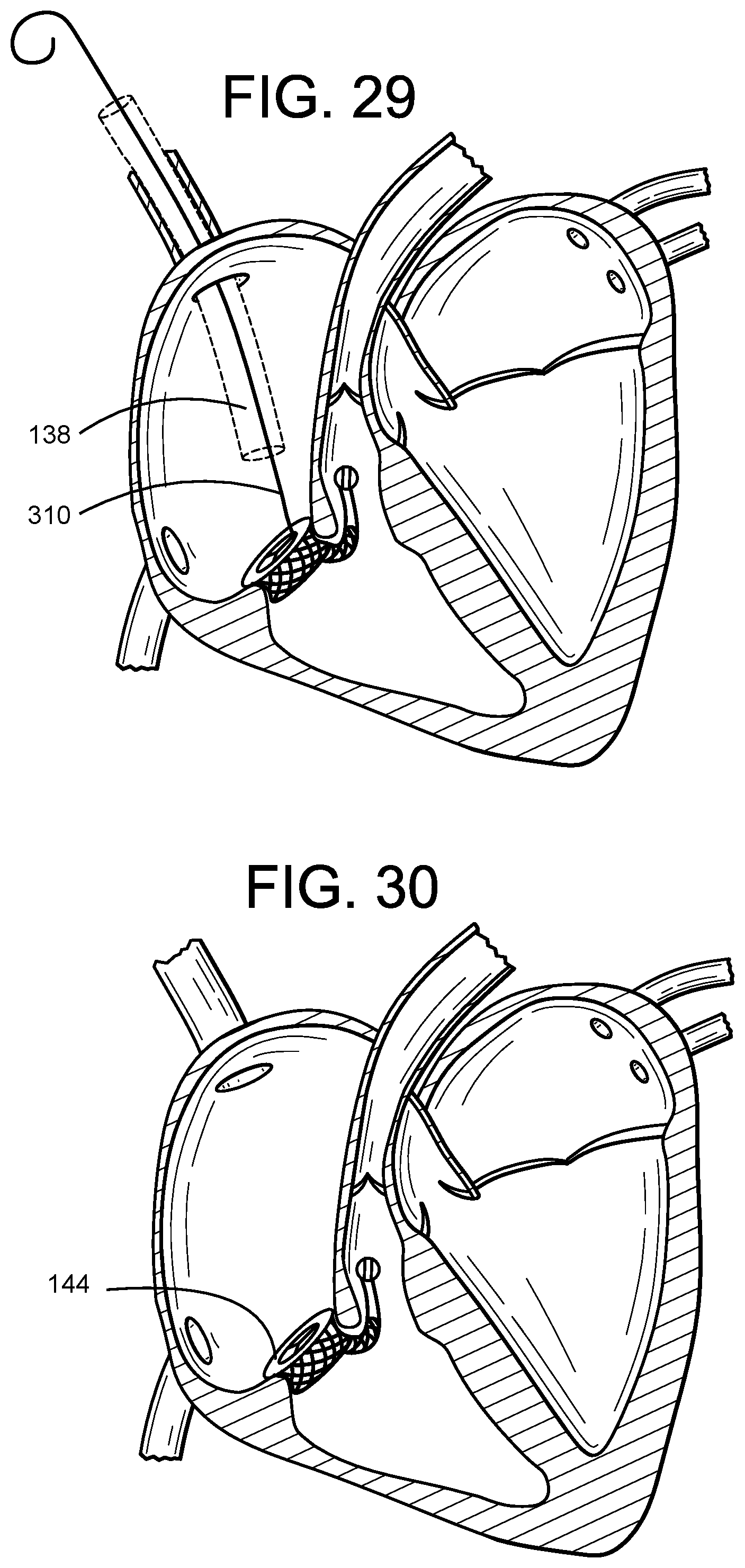
D00013

D00014
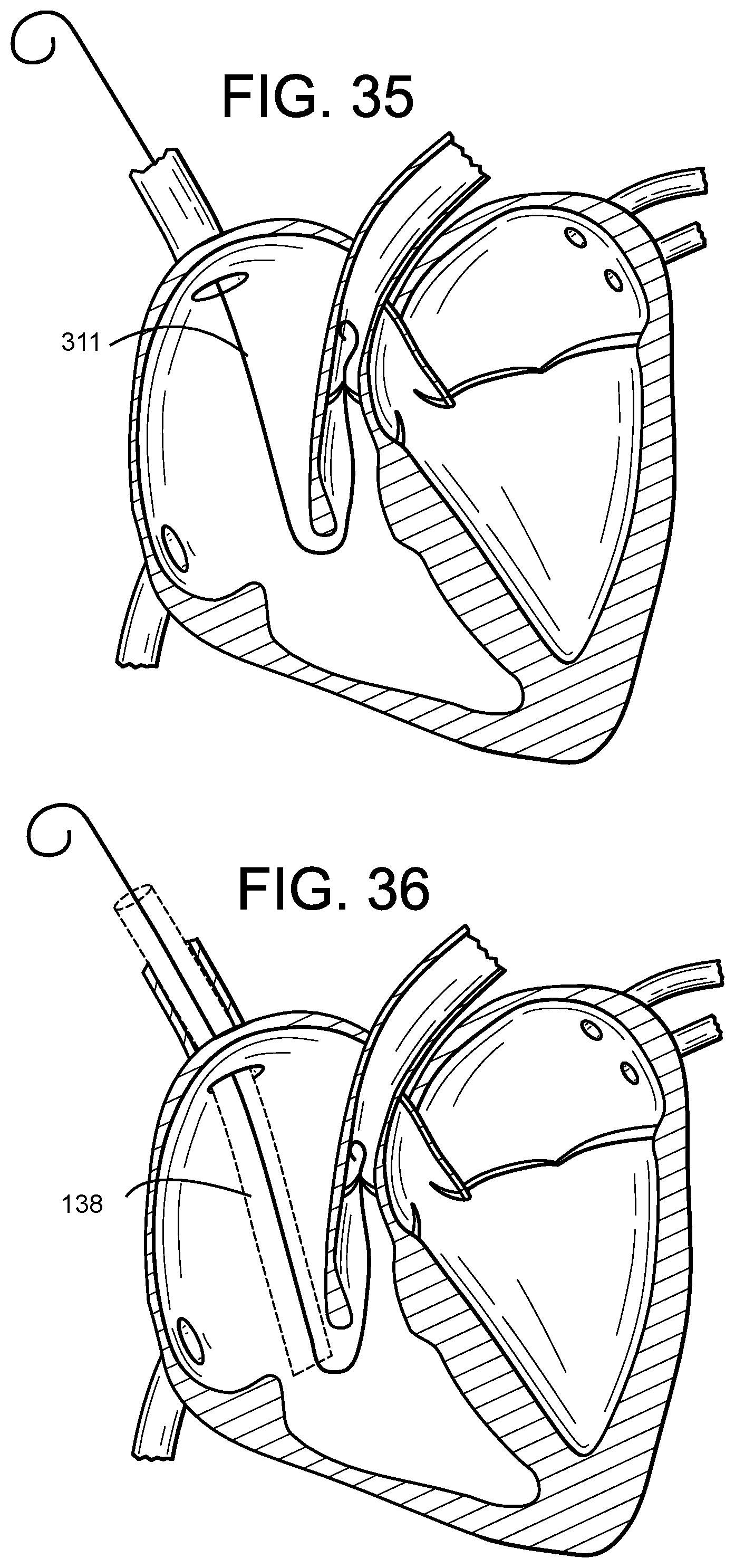
D00015
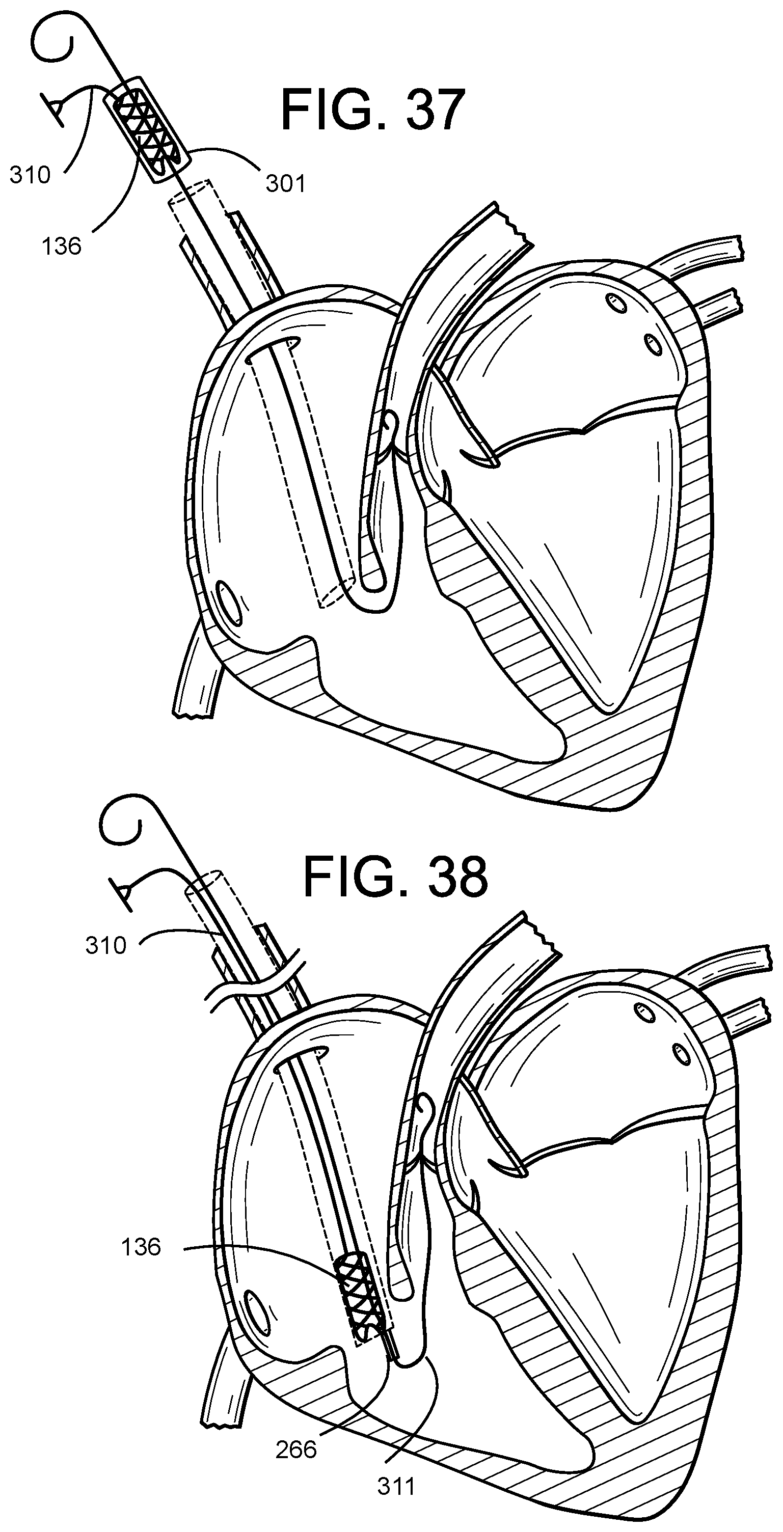
D00016
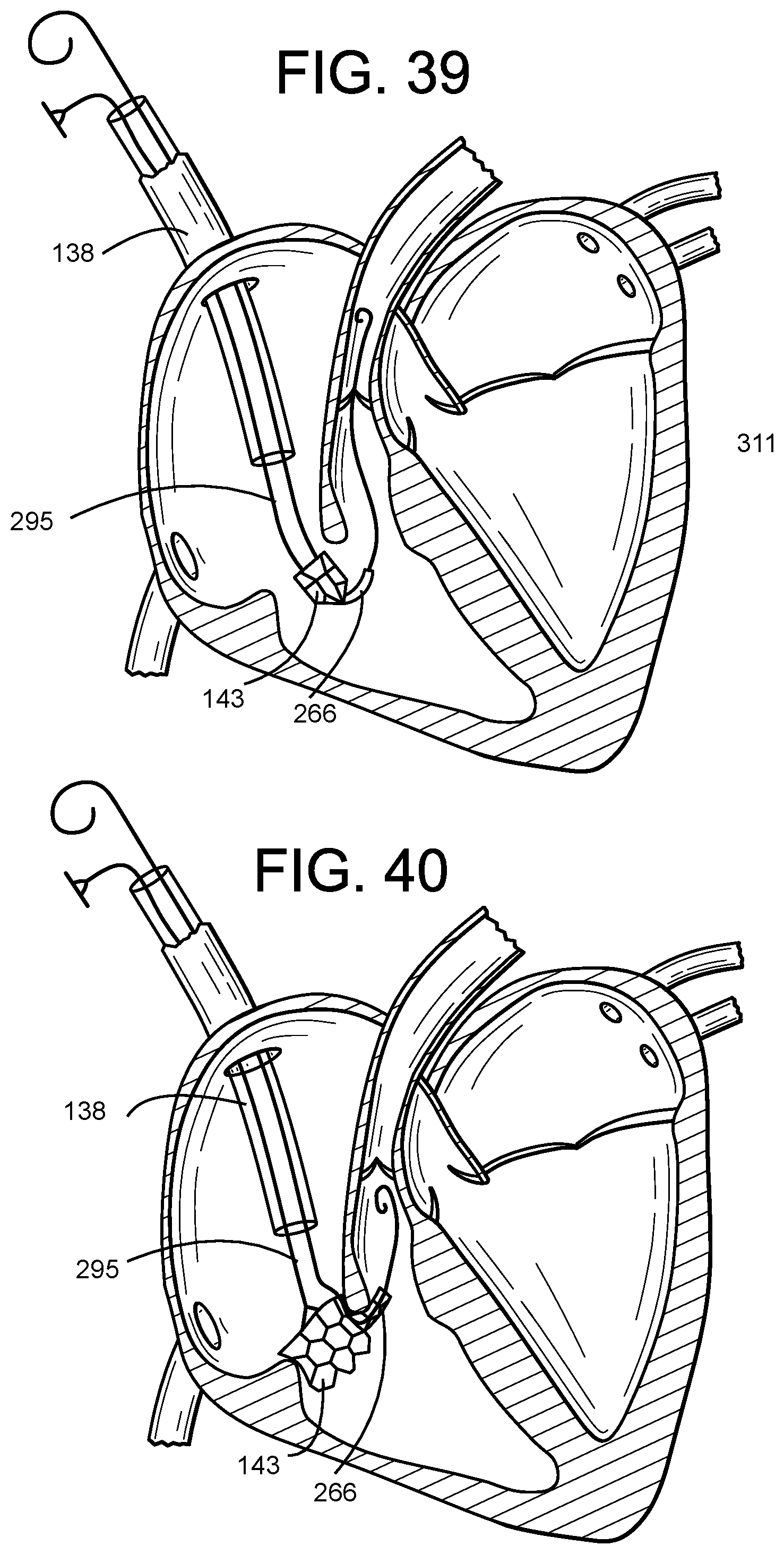
D00017
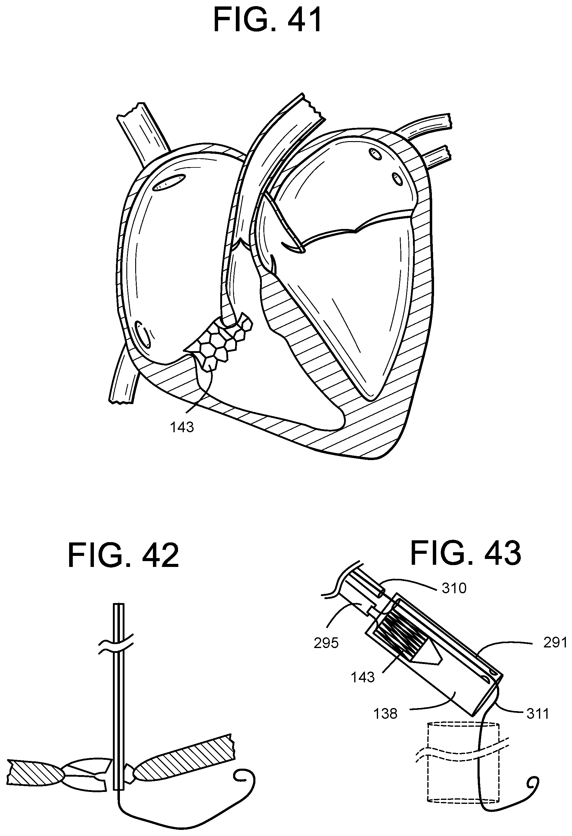
D00018

XML
uspto.report is an independent third-party trademark research tool that is not affiliated, endorsed, or sponsored by the United States Patent and Trademark Office (USPTO) or any other governmental organization. The information provided by uspto.report is based on publicly available data at the time of writing and is intended for informational purposes only.
While we strive to provide accurate and up-to-date information, we do not guarantee the accuracy, completeness, reliability, or suitability of the information displayed on this site. The use of this site is at your own risk. Any reliance you place on such information is therefore strictly at your own risk.
All official trademark data, including owner information, should be verified by visiting the official USPTO website at www.uspto.gov. This site is not intended to replace professional legal advice and should not be used as a substitute for consulting with a legal professional who is knowledgeable about trademark law.