Endoscopic Stapler And Staple
Marczyk; Stanislaw ; et al.
U.S. patent application number 16/720695 was filed with the patent office on 2020-04-23 for endoscopic stapler and staple. The applicant listed for this patent is Covidien LP. Invention is credited to Ernie Aranyi, Stanislaw Kostrzewski, Stanislaw Marczyk.
| Application Number | 20200121320 16/720695 |
| Document ID | / |
| Family ID | 56464089 |
| Filed Date | 2020-04-23 |


View All Diagrams
| United States Patent Application | 20200121320 |
| Kind Code | A1 |
| Marczyk; Stanislaw ; et al. | April 23, 2020 |
ENDOSCOPIC STAPLER AND STAPLE
Abstract
A surgical stapler has a tool assembly including an anvil and a staple cartridge having a series of staples which are supported and configured to be rotatably ejected from the staple cartridge into the anvil to suture tissue. In embodiments, the surgical stapler includes a cartridge that supports a plurality of rotatable pushers. Each pusher supports a curved, substantially U-shaped staple having a single tissue penetrating distal leg portion and a proximal leg portion. The pusher is rotatable to drive the distal leg portion into an anvil to deform the staple into a substantially D-shaped configuration.
| Inventors: | Marczyk; Stanislaw; (Stratford, CT) ; Aranyi; Ernie; (Easton, CT) ; Kostrzewski; Stanislaw; (Newtown, CT) | ||||||||||
| Applicant: |
|
||||||||||
|---|---|---|---|---|---|---|---|---|---|---|---|
| Family ID: | 56464089 | ||||||||||
| Appl. No.: | 16/720695 | ||||||||||
| Filed: | December 19, 2019 |
Related U.S. Patent Documents
| Application Number | Filing Date | Patent Number | ||
|---|---|---|---|---|
| 14803249 | Jul 20, 2015 | 10548599 | ||
| 16720695 | ||||
| Current U.S. Class: | 1/1 |
| Current CPC Class: | A61B 2017/07228 20130101; A61B 17/0644 20130101; A61B 17/068 20130101; A61B 17/072 20130101; A61B 17/105 20130101; A61B 2017/07278 20130101 |
| International Class: | A61B 17/10 20060101 A61B017/10; A61B 17/068 20060101 A61B017/068; A61B 17/064 20060101 A61B017/064; A61B 17/072 20060101 A61B017/072 |
Claims
1. (canceled)
2. A surgical staple and pusher assembly comprising: a surgical staple having a distal leg portion and a proximal leg portion, the distal leg portion including first and second ends and a curved body extending between the first and second ends, the first end of the distal leg portion including a tapered tip, the proximal leg portion including first and second ends, the second end of the proximal leg portion including a blunt tip, the second end of the distal leg portion coupled to the first end of the proximal leg portion, wherein the distal leg portion and the proximal leg portion are configured to have a D-shaped deformed configuration; and a pusher including a body defining a channel and a slot, wherein the channel receives the proximal leg portion of the surgical staple to support the surgical staple on the pusher and the slot is configured to receive a pivot member to facilitate rotation of the pusher about the pivot member.
3. The surgical staple and pusher assembly of claim 2, wherein the slot is defined by a curved surface that facilitates rotation of the pusher about the pivot member.
4. The surgical staple and pusher assembly of claim 2, wherein the proximal leg portion of the surgical staple includes a recessed portion and the channel defined in the body of the pusher includes a bump that is received within the recessed portion of the surgical staple.
5. The surgical staple and pusher assembly of claim 4, wherein the pusher includes a distal end and the channel is defined in the distal end of the pusher such that the surgical staple is supported within the channel distally of the pusher.
6. A surgical stapler comprising: a shaft portion having a distal end portion; a tool assembly supported on the distal end portion of the shaft portion, the tool assembly including an anvil and a cartridge assembly, the cartridge assembly having a cartridge body defining a plurality of staple pockets and a surgical staple and pusher assembly received within each of the plurality of staple pockets, each of the surgical staple and pusher assemblies including: a surgical staple having a distal leg portion and a proximal leg portion, the distal leg portion including first and second ends and a curved body extending between the first and second ends, the first end of the distal leg portion including a tapered tip, the proximal leg portion including first and second ends, the second end of the proximal leg portion including a blunt tip, the second end of the distal leg portion coupled to the first end of the proximal leg portion, wherein the distal leg portion and the proximal leg portion are configured to have a D-shaped deformed configuration; and a pusher including a body defining a channel, wherein the channel receives the proximal leg portion of the surgical staple to support the surgical staple on the pusher; and a drive assembly having a working member that is configured to move through the tool assembly to effect rotatable movement of each of the pushers within a respective one of the staple pockets, wherein rotatable movement of each of the pushers ejects the staple from the respective staple pocket of the cartridge body.
7. The surgical stapler of claim 6, wherein the cartridge body includes a pivot member supported within each of the plurality of staple receiving slots, each of the pushers being rotatably supported on a respective one of the pivot members within a respective one of the plurality of staple receiving slots.
8. The surgical stapler according to claim 7, wherein each of the staple pockets includes a circular wall, each of the circular walls slidably supporting a respective one of the pushers.
9. The surgical stapler according to claim 6, wherein the cartridge body defines at least two rows of staple pockets and at least one channel that extends between the at least two rows of staple pockets.
10. The surgical stapler according to claim 9, further including a sled configured to translate through the at least one channel of the cartridge body, the sled including at least one cam that is positioned to sequentially engage the pushers to effect rotatable movement of the pushers within the cartridge body.
11. The surgical stapler according to claim 10, wherein the sled is positioned within the cartridge body to be engaged and advanced by the working member of the drive assembly.
12. The surgical stapler according to claim 11, wherein each of the pushers is positioned to extend into the at least one channel of the cartridge body such that translation of the sled through the at least one channel causes the at least one cam to contact the pushers in two adjacent rows of the at least two rows of staple pockets to effect rotation of the pushers.
13. The surgical stapler according to claim 12, wherein the at least two rows of staple pockets includes four rows of staple pockets and the at least one cam includes two cams.
14. The surgical stapler according to claim 6, wherein each of the staples includes a single tissue penetrating leg portion.
15. The surgical stapler according to claim 14, wherein each of the plurality of staple pockets is defined by a circular wall and the single tissue penetrating leg portion is curved and is configured to slide along the circular wall defining the respective staple pocket.
16. The surgical stapler according to claim 6, wherein the working member of the drive assembly has an I-beam configuration and includes an upper beam and a lower beam, the upper and lower beams engageable with the anvil and the cartridge assembly to progressively clamp tissue as the working member moves through the tool assembly.
17. The surgical stapler according to claim 16, wherein the cartridge assembly includes a cartridge channel that supports the cartridge body, the surgical stapler further including first and second articulation links, each of the first and second articulation links having a distal end operatively connected to a proximal end of the cartridge channel, the first and second articulation links being axially movable in opposite directions to pivot the tool assembly in relation to the shaft portion.
18. The surgical stapler according to claim 17, further including a pivotal articulation member interconnecting the first articulation link to the second articulation link, wherein pivotal movement of the articulation member causes movement of the first articulation link in one direction and effects movement of the second articulation link in an opposite direction.
19. A surgical staple comprising: a surgical staple including a distal leg portion and a proximal leg portion, the distal leg portion including first and second ends and a curved body extending between the first and second ends, the first end of the distal leg portion including a tapered tip, the proximal leg portion including first and second ends, the second end of the proximal leg portion including a blunt tip, the second end of the distal leg portion coupled to the first end of the proximal leg portion, wherein the distal leg portion and the proximal leg portion are configured to have a D-shaped deformed configuration.
20. The surgical staple of claim 19, wherein the proximal leg portion of the surgical staple includes a recessed portion.
Description
CROSS-REFERENCE TO RELATED APPLICATIONS
[0001] This application is a divisional of U.S. patent application Ser. No. 14/803,249, filed Jul. 20, 2015, the disclosure of which is incorporated by reference herein in its entirety.
TECHNICAL FIELD
[0002] The present disclosure relates to surgical staplers, and more particularly, to surgical staplers for endoscopic use. The present disclosure also relates to surgical staples for use with endoscopic surgical staplers.
BACKGROUND
[0003] Surgical staplers typically include a cartridge housing a plurality of staples, an anvil for forming the staples as the staples are ejected from the cartridge and a knife to effect simultaneous dissection and suturing of tissue. When compared to applying manually threaded sutures, the use of surgical staplers to suture and dissect tissue has increased the speed of the surgical procedure and thus, minimized patient trauma.
[0004] In an endoscopic surgical procedure, a surgical stapler is inserted through a small incision in the skin or through a cannula to access a surgical site within a patent. Typically, staples are driven from a cartridge of the surgical stapler in a direction perpendicular to a tissue contact surface of the cartridge. Due to the complexity of known surgical staplers as well as the staple size requirements of known staple forming apparatus, a continued need exists for small diameter surgical staplers suitable for endoscopic use.
SUMMARY
[0005] The present disclosure is directed to a surgical stapler having a tool assembly including an anvil and a staple cartridge having a series of staples which are supported and configured to be rotatably ejected from the staple cartridge into the anvil to suture tissue. The manner in which the staples are supported and ejected from within the staple cartridge facilitates the use of a small diameter tool assembly that includes staples capable of suturing thicker tissues than would normally be associated with tool assemblies with such a small diameter.
[0006] In embodiments, the surgical stapler includes a cartridge that supports a plurality of rotatable pushers. Each pusher supports a curved, substantially U-shaped staple having a single tissue penetrating distal leg portion and a proximal leg portion. The pusher is rotatable to drive the distal leg portion into an anvil to deform the staple into a substantially D-shaped configuration.
[0007] In one aspect of the disclosure, a surgical stapler includes a shaft portion, and a tool assembly supported on a distal end of the shaft portion. The tool assembly includes an anvil and a cartridge assembly. The cartridge assembly includes a cartridge body defining a plurality of staple pockets, a pusher rotatably supported in each of the staple pockets, and a staple supported on each of the pushers. A drive assembly has a working member that is configured to move through the tool assembly to effect rotatable movement of each of the pushers within a respective one of the staple pockets, wherein rotatable movement of each of the pushers ejects the staple from the respective staple pocket of the cartridge body.
[0008] In embodiments, each of the staple pockets includes a pivot member and each of the pushers is rotatably supported on a respective one of the pivot members.
[0009] In some embodiments, each of the staple pockets includes a circular wall and each of the circular walls slidably supports a respective one of the pushers.
[0010] In certain embodiments, the cartridge body defines at least two rows of staple pockets and at least one channel that extends between the at least two rows of staple pockets.
[0011] In embodiments, the surgical stapler includes a sled configured to translate through the at least one channel. The sled includes at least one cam that is positioned to sequentially engage the pushers to effect rotatable movement of the pushers within the cartridge body.
[0012] In some embodiments, the sled is positioned within the cartridge body to be engaged and advanced by the working member of the drive assembly.
[0013] In certain embodiments, each of the pushers is positioned to extend into the at least one channel of the cartridge body such that translation of the sled through the at least one channel causes the at least one cam to contact the pushers in two adjacent rows of the at least two rows of staple pockets to effect rotation of the pushers.
[0014] In embodiments, the at least two rows of staple pockets includes four rows of staple pockets and the at least one cam includes two cams.
[0015] In some embodiments, each of the staples includes a single tissue penetrating leg portion.
[0016] In certain embodiments, the single tissue penetrating leg portion has a first end defining a tapered tip and a second end connected to a proximal leg portion. The proximal leg portion is supported on one of the pushers.
[0017] In embodiments, each of the pushers includes a body defining a channel and the proximal leg portion of each of the staples is supported within the channel.
[0018] In some embodiments, the single tissue penetrating leg portion is curved and is configured to slide along the circular wall of the staple pocket.
[0019] In certain embodiments, the cartridge assembly includes a cartridge channel that supports the cartridge body and the surgical stapler further includes first and second articulation links. Each of the first and second articulation links has a distal end operatively connected to a proximal end of the cartridge channel. The first and second articulation links are axially movable in opposite directions to pivot the tool assembly in relation to the shaft portion.
[0020] In embodiments, the surgical stapler further includes a pivotable articulation member interconnecting the first articulation link with the second articulation link, wherein pivotable movement of the articulation member causes movement of the first articulation link in one direction and effects movement of the second articulation link in an opposite direction.
[0021] In some embodiments, each of the pushers defines a slot dimensioned to receive the pivot member such that the pusher is to rotatably supported within a respective one of the plurality of staple pockets.
[0022] In certain embodiments, the blunt proximal leg portion of each of the staples includes a curved portion and the channel includes a bump. The bump interacts with the curved portion to retain the staple within a respective one of the plurality of staple pockets.
[0023] In embodiments, the working member of the drive assembly has a I-beam configuration including an upper beam and a lower beam. The upper and lower beams are engageable with the anvil and the cartridge assembly to progressively clamp tissue as the working member moves through the tool assembly.
[0024] In another aspect of the disclosure, a surgical staple includes a distal tissue penetrating leg portion including a first end having a tapered tip, a curved body, and a second end, and a proximal leg portion connected to the second end of the tissue penetrating leg portion. The proximal leg portion is configured to be received on a pusher, wherein the distal tissue penetrating leg portion and the proximal leg portion are configured to have a D-shaped deformed configuration.
[0025] In another aspect of the disclosure, a tool assembly includes an anvil and a cartridge assembly. The cartridge assembly has a cartridge body defining a plurality of staple pockets, a pusher rotatably supported in each of the staple pockets, and a staple supported on each of the pushers.
[0026] In embodiments, each of the staple pockets includes a pivot member and each of the pushers is rotatably supported on a respective one of the pivot members.
[0027] In some embodiments, each of the staple pockets includes a circular wall that slidably supports a respective one of the pushers.
[0028] In certain embodiments, the cartridge body defines at least two rows of staple pockets and at least one channel that extends between the at least two rows of staple pockets.
[0029] In embodiments, the surgical stapler further includes a sled configured to translate through the at least one channel. The sled includes at least one cam that is positioned to sequentially engage the pushers to effect rotatable movement of the pushers within the cartridge body.
BRIEF DESCRIPTION OF THE DRAWINGS
[0030] Various embodiments of the presently disclosed surgical stapler and surgical staple are described herein with reference to the drawings, wherein:
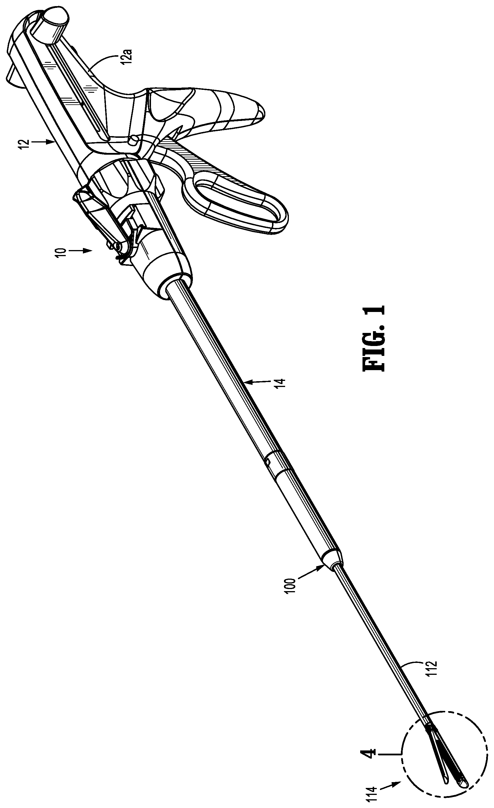
[0031] FIG. 1 is a side perspective view of one embodiment of the presently disclosed surgical stapler in an unapproximated position;
[0032] FIG. 1A is a side perspective view from the distal end of a stapler reload of the surgical stapler shown in FIG. 1;
[0033] FIG. 2 is a side perspective view from the proximal end of the surgical stapler reload shown in FIG. 1A;
[0034] FIG. 3 is a side perspective, exploded view of the surgical stapler reload shown in FIG. 1A;
[0035] FIG. 3A is an enlarged view of the indicated area of detail shown in 3;
[0036] FIG. 3B is an enlarged view of the indicated area of detail shown in FIG. 3;
[0037] FIG. 4 is an enlarged view of the indicated area of detail shown in FIG. 1;
[0038] FIG. 5 is a cross-sectional taken along section line 5-5 of FIG. 4;
[0039] FIG. 6 is an enlarged view of the indicated area of detail shown in FIG. 3A;
[0040] FIG. 7 is a top view of the cartridge body of the cartridge assembly of the surgical stapler reload shown in FIG. 1A;
[0041] FIG. 8 is a bottom view of the cartridge body, pushers and sled of the cartridge assembly of the surgical stapler reload shown in FIG. 1A;
[0042] FIG. 9 is a cross-sectional view taken along section line 9-9 of FIG. 7;
[0043] FIG. 10 is a cross-sectional view taken along section line 10-10 of FIG. 7;
[0044] FIG. 11 is an enlarged view of the indicated area shown in FIG. 10;
[0045] FIG. 12 is a side perspective view with parts separated of the staple and pusher of the cartridge assembly of the surgical stapler reload shown in FIG. 1A assembled;
[0046] FIG. 13 is a side perspective view from the distal end of the staple and pusher of the cartridge assembly of the surgical stapler reload shown in FIG. 1A;
[0047] FIG. 14 is a side perspective view from the proximal end of a staple and a pusher of the cartridge assembly of the surgical stapler reload shown in FIG. 1A;
[0048] FIG. 15 is a side cross-sectional view taken along section line 15-15 of FIG. 4;
[0049] FIG. 16 is an enlarged view of the indicated area of detail shown in FIG. 15;
[0050] FIG. 17 is a top view of the surgical stapler reload shown in FIG. 1A;
[0051] FIG. 18 is a side cross-sectional view taken along section line 18-18 of FIG. 17;
[0052] FIG. 19 is a cross-sectional view taken along section line 19-19 of FIG. 18;
[0053] FIG. 20 a cross-sectional view taken along section line 20-20 of FIG. 18;
[0054] FIG. 21 a cross-sectional view taken along section line 21-21 of FIG. 17;
[0055] FIG. 22 is an enlarged view of the indicated area of detail shown in FIG. 21;
[0056] FIG. 23 is an enlarged view of the indicated area of detail shown in FIG. 18;
[0057] FIG. 24 is a side perspective view of the tool assembly of the stapler reload of the surgical stapler shown in FIG. 1 with the tool assembly in the approximated position prior to firing;
[0058] FIG. 25 is a cross-sectional view through the tool assembly shown in FIG. 24;
[0059] FIG. 26 is an enlarged view of the indicated area of detail shown in FIG. 25;
[0060] FIG. 27 is a side cross-sectional view of the tool assembly of the stapler reload of the surgical stapler shown in FIG. 1 with the tool assembly in the approximated position and drive member partially advanced to fire staples from the cartridge assembly;
[0061] FIG. 28 is an enlarged view of the indicated area of detail shown in FIG. 27;
[0062] FIG. 29 is a side view of the staples of the of the tool assembly of the stapler reload of the surgical stapler shown in FIG. 1 after the staples have been formed in tissue;
[0063] FIG. 30 is a transverse cross-sectional view through the working end of the drive member of the tool assembly shown in FIG. 27 as staples are being fired;
[0064] FIG. 31 is a side, perspective view of the stapler reload shown in FIG. 1A in a non-articulated and unapproximated position with the proximal tube of the proximal body portion and the shaft tube of the shaft portion removed;
[0065] FIG. 32 is a top perspective view of the proximal body portion of the stapler reload shown in FIG. 31 with the proximal tube and the upper housing half section removed;
[0066] FIG. 33 is a top perspective view of the upper housing half-section of the proximal body portion of the stapler reload shown in FIG. 31;
[0067] FIG. 34 is a top, perspective view of the proximal body portion of the stapler reload shown in FIG. 33 with the proximal tube and the upper housing half section removed and the articulation member rotated; and
[0068] FIG. 35 is a top view of the tool assembly of the stapler reload shown in FIG. 31 in an articulated position.
DETAILED DESCRIPTION OF EMBODIMENTS
[0069] Embodiments of the presently disclosed endoscopic surgical stapler including staples for endoscopic use will now be described in detail with reference to the drawings wherein like reference numerals designate identical or corresponding elements in each of the several views. In this description, the term "proximal" is used generally to refer to the portion of the apparatus that is closer to a clinician, while the term "distal" is used generally to refer to the portion of the apparatus that is farther from the clinician. In addition, the term "endoscopic" is used generally to refer to endoscopic, laparoscopic, or arthroscopic apparatus or procedures as well as any other surgical apparatus or procedure that is configured to extend or be performed through a small incision or a cannula inserted into a patient's body. Finally, the term "clinician" is used generally to refer to medical personnel including doctors, nurses, and support personnel.
[0070] The presently disclosed surgical stapler includes a tool assembly which supports a plurality of staples which are supported and configured to be rotatably ejected from a staple cartridge into an anvil to suture tissue. The manner in which the staples are supported and ejected from within the staple cartridge facilitates the use of a small diameter tool assembly which includes staples capable of suturing thicker tissues than would normally be associated with tool assemblies with such a small diameter. In embodiments, the surgical stapler includes a cartridge that supports a plurality of rotatable pushers. Each pusher supports a substantially U-shaped staple having a single tissue penetrating distal leg portion and a proximal leg portion. The distal leg portion is positioned on the pusher to be driven into an anvil to deform the U-shaped staple into a substantially D-shape.
[0071] FIG. 1-2 illustrate the presently disclosed surgical stapler 10 which includes an actuating device 12 having a handle assembly 12a, a body portion 14 that extends distally from the handle portion 12a, and a stapler reload 100 supported on a distal end of the body portion 14. The distal end of the body portion 14 is adapted to releasably engage a proximal end of the reload 100 such that actuation of the actuating device 12 effects operation of the reload 100. Suitable actuating devices are disclosed in detail in U.S. Pat. No. 5,865,361 ("361 patent") and U.S. Pat. No. 7,143,924 ("924 patent") which are incorporated herein in their entirety by reference. Although the presently disclosed actuating device is illustrated as a manually actuated handle assembly, it is envisioned that other known actuating devices including robotic devices, motorized devices, and/or electrically or mechanically driven devices can be used to actuate the reload 100.
[0072] In alternate embodiments, the reload 100 can be fixedly attached to the distal end of the handle assembly 12. In such embodiments, a cartridge assembly of a tool assembly may be removable to facilitate reuse of the surgical stapler 10.
[0073] Referring to FIGS. 1A-3, the reload 100 includes a proximal body portion 110, an elongated shaft portion 112 and a tool assembly 114. The proximal body portion 110 includes an inner housing 116 (FIG. 23) including an upper housing half-section 116a and a lower housing half-section 116b. The housing half-sections 116a and 116b define channels which slidably receive a proximal drive member 118, a first articulation link 120 and a second articulation link 122. The first articulation link 120 is connected to the second articulation link 122 by an articulation member 123 which will be described in detail below. The housing half-sections 116a and 116b are received within a proximal body tube 125.
[0074] Referring to FIGS. 3-3B, the proximal drive member 118 supports a drive coupler 124 that is adapted to engage a control rod (not shown) of the actuating device 12 (FIG. 1) to operate the tool assembly 114 of the reload 100. The proximal drive member 118 also supports a locking assembly 126 which includes a locking device 128 and a spring 130. Operation of the drive coupler 124 and the locking assembly 126 are described in the '361 patent. Accordingly, the drive coupler 124 and locking assembly 126 will not be described in further detail herein. A distal end of the proximal drive member 118 includes a T-shaped recess 118a. In addition, the distal ends of the first articulation link 120 and the second articulation link 122 include hook portions 120a and 122a, respectively (FIG. 3B). Each of these hook portions 120a and 122a and the T-shaped recess 118a are described in further detail below.
[0075] The elongated shaft portion 112 of the reload 100 includes an inner housing 134 (FIG. 18) including upper and lower housing half-sections 134a and 134b which are received within a shaft portion tube 112a. A proximal end of the inner housing 134 of the elongated shaft portion 112 is received within the distal end of the inner housing 116 of the proximal body portion 110 and includes an annular recess 135 (FIG. 23). The annular recess 135 receives a protrusion 116c formed within the inner housing 116 to axially secure the inner housing 116 of the proximal body portion 110 to the inner housing 134 of the shaft portion 112. The upper and lower housing half-sections 134a, 134b of the elongated shaft portion 112 define internal channels (not shown) which slidably receive a pair of distal drive members 136a, 136b and a pair of articulation rods 140a, 140b. A proximal end of each of the articulation rods 140a, 140b defines a cutout 142a, 142b, respectively. The cutouts 142a, 142b of the articulation rods 140a, 140b receive one side of the hook portions 120a, 122a, (FIG. 3B), respectively, of the first and second articulation links 120, 122. When the hook portions 120a, 122a are received within the cutouts 142a, 142b of the articulation rods 140c, 140b, linear movement of the first and second articulation links 120, 122 effects linear movement of the articulation rods 140a, 140b as described in further detail below.
[0076] A proximal end of each of the distal drive members 136a, 136b includes a hook portion 144a and defines a recess 144b. Each of the recesses 144b is defined by a distal wall 144c. The proximal drive member 118 and the proximal end of the distal drive members 136a, 136b are connected by a drive member link 119. The drive member link 119 has a proximal end 119a (FIG. 23) configured to be received in the T-shaped slot 118a of the proximal drive member 118. A distal end of the drive member link 119 includes a hook portion 119b and defines a recess 119c. The hook portion 119b is received within the recesses 144b of the distal drive members 136a, 136b such that the hook portions 144a of the distal drive members 136a, 136b are slidably received within the recess 119c of the drive member link 119. Movement of the proximal drive member 118 effects corresponding movement of the drive member link 119. As the drive member link 119 is moved distally, the hook portion 119b of the drive member link 119 moves within the recesses 144b of the distal drive members 136a, 136b such that the drive member link 119 moves independently of the drive members 136a, 136b. When the hook member 119a of the drive member link 119 engages the distal walls 144c defining the recesses 144b of the distal drive members 136a, 136b, distal movement of the drive member link 119 will effect corresponding distal movement of the distal drive members 136a, 136b. By controlling the length the recesses 144b, the length of movement or the stroke of the drive members 136a, 136b can be controlled to facilitate use of the components of the proximal body portion 110 of the reload 100 with different length tool assemblies 114. It is envisioned that the proximal drive member 118, the drive member link 119, and/or the distal drive members 136a, 136b can be formed as a unitary component.
[0077] Referring to FIGS. 3-5, the distal end of each of the distal drive members 136a and 136b is secured to a working member 150 (FIG. 5) such as by welding to form a drive assembly 151. Alternately, other securement techniques can be used to secure the distal end of the drive members 136a, 136b to the working member 150. In one embodiment, the working member 150 includes an upper beam 152, a lower beam 154 and a vertical strut 156 interconnecting the upper and lower beams 152, 154. A cutting edge 156a is formed or supported on a distal end of the vertical strut 156. The vertical strut 156 is configured to translate through the tool assembly 114 when the tool assembly 114 is actuated by the actuating device 12 to fire the staples and dissect tissue. More specifically, the vertical strut 156 is positioned to translate through a knife slot 188 formed in a cartridge body 184 of a cartridge assembly 180 and a slot 212 formed in the anvil 182 to dissect tissue clamped between the anvil 180 and the cartridge body 184 and eject staples from the cartridge body 184 as will be described in further detail below.
[0078] Referring again to FIGS. 3 and 3A, the cartridge body 184 is supported within a cartridge channel 186 (FIG. 3A) of the cartridge assembly 180. The cartridge channel 186 includes a pivot member 157 that is secured to a distal end of the shaft housing half-sections 134a, 134b by upper and lower connecting members 160a, 160b. Each connecting member 160a, 160b includes a distal end which defines an opening 162 and a proximal end 164 which has a stepped configuration. The stepped configuration of the proximal end 164 of each connecting member 160a, 160b is received within a cutout 166 formed in the distal end of each of the upper and lower shaft housing half-sections 134a, 134b to axially fix the upper and lower connecting members 160a, 160b to the upper and lower shaft housing half-sections 134a, 134b, respectively. The openings 162 of each of the upper and lower connecting members 160a, 160b receive a respective pivot pin 170 (only one shown, FIG. 3A) formed on the upper and lower surfaces of the pivot member 157 to pivotally secure the pivot member 157, and thus, the cartridge channel 186, to the shaft housing half-sections 134a, 134b. A screw 173a and a washer 173b are provided to secure each of the connecting members 160a, 160b to the pivot member 157. The pivot member 157 also includes two transversely extending bores 172. Each of the bores 172 receives a pin 210 that also passes through an opening 210a (FIG. 3A) in a distal end of the articulation rods 140a, 140b to secure the pivot member 157 between the distal ends of the articulation rods 140a, 140b. As discussed in further detail below, when the articulation rods 140a, 140b are translated in opposite directions, the cartridge channel 186 is pivoted about an axis defined by the pivot pins 170 to pivot the tool assembly 114 in relation to the elongated shaft portion 112 of the reload 100.
[0079] Referring to FIGS. 3-6, the cartridge assembly 180 (FIG. 6) includes the cartridge body 184, the cartridge channel 186, a plurality of pushers 187, a sled 189, and a plurality of staples 190. The cartridge body 184 includes a tapered distal end 184a that functions as a tissue guide to direct tissue between the anvil 182 and the cartridge body 184. The cartridge channel 186 defines a recess 192 (FIG. 3A) that receives the cartridge body 184 and an elongated slot 186a that is aligned with the knife slot 188 formed in the cartridge body 184. The recess 192 is defined in part by sidewalls 194 of the cartridge channel 186. In embodiments, each of the sidewalls 194 defines a cutout 196 that receives protrusions 184a formed on the outer surface of the cartridge body 184 to secure the cartridge body 184 within the recess 192 of the cartridge channel 186. It is envisioned that other techniques may be used to secure the cartridge body 184 within the cartridge channel 186.
[0080] In embodiments, the sidewalls 194 of the cartridge channel 186 defines openings 198 that receive pivot members 200 (FIG. 3A). The pivot members 200 extend through openings 202 defined in the proximal end of the anvil 182 and into the openings 198 in the cartridge channel 186 to pivotally secure the anvil 182 to the cartridge channel 186.
[0081] The anvil 182 includes a tissue engaging surface 208 that defines a plurality of anvil pockets 210 (FIG. 28) that receive the staples 190. As discussed above, the anvil 182 defines an elongated slot 212 that receives the vertical strut 156 of the working member 150 of the drive assembly 151. The anvil 182 also defines an elongated recess 214 that slidably receives the upper beam 152 of the working member 150. The elongated recess 214 defines a proximal cam surface 216. When the upper beam 152 engages the proximal cam surface 216 as the working member 150 is translated distally through the elongated recess 214 of the anvil 182, the upper beam 152 of the working member 150 urges the anvil 182 towards the cartridge body 184 to move the tool assembly 114 to a clamped or approximated position. A biasing member, e.g., leaf spring 220, is supported in a slot 222 (FIG. 3A) defined between the proximal end of the anvil 182 and the distal end of the pivot member 157 of the cartridge channel 186 to urge the anvil 182 away from the cartridge body 184 to an open or unclamped position.
[0082] Referring to FIG. 6, the sled 189 is positioned within the cartridge body 184 immediately distal of the working member 150 and includes cams 226 and a central rib 228. The cartridge body 184 defines channels 236. The sled 189 is configured to translate through the cartridge body 184 in response to translation of the working member 150 of the drive assembly 151 through the cartridge body 184 to effect translation of the central rib 228 through the knife slot 188 of the cartridge body 184 and translation of the cams 226 through the channels 236 of the cartridge body 184. The central rib 228 of the sled 189 defines detents 230 that receive protrusions 232 formed on the cartridge body 184 adjacent the proximal end of the knife slot 188 to releasably retain the sled 189 in a proximal position within the cartridge body 184. The cams 226 of the sled 189 are positioned to slide through channels 236 defined in the cartridge body 184 to engage the pushers 187 and eject the staples 190 from the cartridge body 184 as discussed in further detail below.
[0083] Referring also to FIGS. 7-11, the cartridge body 184 defines a plurality of staple pockets 240 which are positioned adjacent the channels 236 (FIG. 11) within the cartridge body 184. Each staple pocket 240 opens onto a tissue contacting surface 241 of the cartridge body 184 and includes a circular wall 242 and a pivot member 244. Each circular wall 242 supports a pusher 187 and the staple 190 such that each pusher 187 extends partially into a respective channel 236 of the cartridge body 184
[0084] Referring also to FIGS. 12-16, each staple 190 has a distal tissue penetrating leg portion 190a and a proximal blunt leg portion 190b. The distal leg portion 190a has a tapered tip 250 configured to penetrate tissue and a curved body configured to rest on the circular wall 242 of the staple pocket 240. The proximal leg portion 190b includes a recessed or curved portion 252 that is configured to retain the staple 190 in engagement with the pusher 187.
[0085] Each pusher 187 has a body 256 defining a channel 260 configured to receive the proximal leg portion 190b of one of the staples 190 and a slot 262 dimensioned to receive the pivot member 244 of the cartridge body 184. The channel 260 includes a curved portion or bump 260a that interacts with the curved portion 252 of the proximal blunt leg portion 190b to retain the staple 190 in the staple pocket 240. One end of the slot 262 includes a curved surface 262a that is configured to facilitate rotation of the pusher 187 about the pivot member 244 of the cartridge body 184 within the staple pocket 240. The body 256 of the pusher 187 also has a curved lower surface 256a that is positioned to slide along the circular wall 242 of the staple pocket 240 as the pusher 187 is rotated within the staple pocket 240. As discussed above, when each respective pusher 187 and staple 190 are supported within a staple pocket 240, each pusher 187 extends into a respective channel 236 of the cartridge body 184 in a position to engage one of the cams 226 of the sled 189 as the sled 189 translates through the cartridge body 184. When the sled 189 translates through cartridge body 184, the cams 226 of the sled 189 engage and rotate respective pushers 187 to sequentially eject the staples 190 from the cartridge body 184 as discussed in further detail below.
[0086] The slot 262 of the body 256 of each of the pushers 187 is positioned to receive the pivot members 244 to rotatably support each of the pushers 187 within a respective staple pocket 240. The slots 262 provide flexibility to the pushers 187 and help during assembly of the cartridge assembly 180 to overcome a small interference that holds each of the pushers 187 engaged with the pivot members 244 in the cartridge body 184.
[0087] Referring briefly again to FIG. 3, the reload 100 includes a locking member 300 which is rotatably supported about a proximal end of the inner housing 116 of the proximal body portion 110. The locking member 300 is movable from a first position in which the locking member 300 blocks distal movement of the proximal drive member 118 to a second position in which the locking member 300 moves to a position to allow distal movement of the proximal drive member 118. U.S. Pat. No. 7,143,924 describes the locking member 300 and its method of operation in detail and is incorporated herein by reference in its entirety.
[0088] Referring to FIGS. 17-23, when the proximal drive member 118 (FIG. 23) is in a retracted position, the drive member link 119 and, thus, the distal drive members 136a, 136b (FIG. 21) are also in a retracted position. In the retracted position, the hook portion 119a of the drive member link 119 is received within the recesses 144b of the distal drive members 136a, 136b (FIG. 3). In addition, the distal end of the upper beam 152 (FIG. 17) of the working member 150 is positioned proximally of the cam surface 216 (FIG. 18) of the anvil 182 to allow the spring 220 (FIG. 22) to move the anvil 182 to the unclamped or open position spaced from the cartridge body 184. As illustrated, the spring 220 is positioned in the slot 222 and presses against the proximal end of the anvil 182 to urge the anvil 182 towards the clamped position. As discussed above, the sled 189 is positioned immediately distal of the working end 150 of the drive assembly 151. Prior to advancement of the working member 150, the sled 189 is positioned proximally of the pushers 187 and staples 190 (FIG. 22).
[0089] Referring to FIGS. 24-26, when the proximal drive member 118 (FIG. 23) is advanced via operation of the actuating device 12 (FIG. 1), the hook portion 119a (FIG. 18) of the drive member link 119 translates through the recesses 144b of the distal drive members 136a, 136b into engagement with a wall 144c defining a distal end of the recesses 144b of the distal drive members 136a, 136b. When this occurs, further distal movement of the drive member link 119 effects corresponding distal movement of the distal drive members 136a, 136b to effect distal movement of the working end 150 of the drive assembly 151.
[0090] Distal movement of the working member 150 of the drive assembly in relation to the anvil 182 advances the upper beam 152 of the working member 150 into engagement with the proximal cam surface 216 of the anvil 182. Engagement of the upper beam 152 with the proximal cam surface 216 urges the anvil 182 against the bias of the leaf spring 220 towards the cartridge body 184 to move the tool assembly 114 to the clamped or approximated position (FIG. 26). In the approximated position of the tool assembly 114, the cams 226 of the sled 189 are positioned immediately proximal of the proximal-most pushers 187.
[0091] Referring to FIGS. 27-30, continued advancement of the proximal drive member 118 (FIG. 23) advances the working member 150 of the drive assembly 151 through the cartridge body 184 to drive the sled 189 through the cartridge body 184. As the working member 150 advances through the cartridge body 184, the upper beam 152 engages the anvil 182 and the lower beam 154 engages the cartridge channel 186 to progressively clamp tissue as the working member 150 advances through the cartridge body 184. Movement of the sled 189 through the cartridge body 184 moves the cams 226 of the sled 189 through the channels 236 in the cartridge body 184 into sequential engagement with the pushers 187 to rotate the pushers 187 about the pivot members 244 formed within each staple pocket 240. As the pushers 187 are rotated about a respective pivot member 244 within a staple pocket 240, each staple 190 is pivoted or rotated upwardly with the respective pusher 187 to direct the tapered tip 250 of the staple 190 through tissue T into an anvil pocket 210 of the anvil 182 to initiate deformation of the staple 190 (FIG. 28). As the pusher 187 and a respective staple 190 are rotated within a staple pocket 240, the curved body 252 of the staples 190 is guided from the staple pocket 240 into the anvil pockets 210 by the circular walls 242 of the staple pockets 240. The staples 190 are configured to define a substantially D-shaped configuration when deformed (FIG. 29).
[0092] As discussed above, the deformed staples 190 are substantially D-shaped. When the tool assembly 114 is returned to the open or unclamped position by retracting the working member 150 through the cartridge body 184 after the staples 190 are fired, the staples 190 are free to be disengaged from the pivot members 244.
[0093] Referring to FIGS. 3 and 31-35, the tool assembly 114 can be articulated by movement of the articulation rods 140a, 140b in opposite directions in relation to each other. As discussed above, the articulation rods 140a, 140b extend from the proximal body portion 110 through the elongated shaft portion 112 to the tool assembly 114. A distal end of each of the articulation rods 140a, 140b is connected to the pivot member 157 by pins 172 (FIG. 3A) that extend through the distal openings 210a of the articulation rods 140a, 140b into the bores 172 of the pivot member 157. As discussed above, the proximal ends of the articulation rods 140a, 140b include cutouts 142a, 142b (FIG. 3B), respectively, that receive one side of hook portions 120a, 122a of the articulation links 120, 122, respectively, to connect the articulation links 120, 122 to the articulation rods 140a, 140b. The first and second articulation links 120, 122 are slidably supported between the housing halves 116a, 116b of the proximal body portion 110. The first articulation link 120 has a distal end connected to the articulation rods 140a and a proximal end connected to an articulation assembly 350 (FIG. 1) of the actuating device 12 (FIG. 1).
[0094] The articulation member 123 includes a C-shaped body 302 having spaced fingers 304, 306 and a central opening 308 (FIG. 32). The fingers 304, 306 are received in cutouts 310 (FIG. 3B) formed in the distal end of first and second articulation links 120 and 122. The central opening 308 receives a housing post 312 (FIG. 33) formed on housing half 116b of the central body portion 110 (FIG. 1) to rotatably support the C-shaped body 302 on the housing half-section 116b. A nut 318 is provided to secure the C-shaped body on the post 312. The nut 318 can be pressed onto the post 312. In use, movement of the first articulation link 120 in one direction as indicated by arrow "A" in FIG. 34 causes the articulation member 123 to pivot about the housing post 312 and effect movement of the second articulation link 122 in a second direction as indicated by arrow "B".
[0095] In use, when the first articulation link 120 is moved by the articulation assembly 350 (FIG. 1) of the actuating device 12 in direction A, the articulation rod 140a, which is connected to link 120 via placement of hook portion 120a in cutout 142a (FIG. 3B), is also moved in direction A. Movement of the first articulation link 120 in direction A effects pivotal movement of the articulation member 123 which causes movement of the second articulation link 122 in the direction of arrow B. Movement of the second articulation link 122 in direction of arrow B causes movement of articulation rod 140b in the direction of arrow B.
[0096] As discussed above, the distal ends of articulation rods 140a and 140b are connected to opposite sides of the pivot member 157 by pins 172. As the articulation rods 140a, 140b are moved in opposite directions, the pivot member 157 is pivoted about the pivot pin 170 to pivot the cartridge channel 186 of the cartridge assembly 180 in relation to shaft portion 112 of the reload 100. Since the cartridge channel 186 is secured to the anvil 182 and supports the cartridge body 184, pivotal movement of the cartridge channel 186 causes pivotal movement of the tool assembly 114 about the pivot pins 170 such that the longitudinal axis of the tool assembly 114 moves from a position aligned with the longitudinal axis of the shaft portion 112 (FIG. 31) to a position at an angle to the longitudinal axis of the shaft portion 112. It is noted that the distal drive members 136a, 136b are formed of a resilient material such as spring steel to facilitate movement of the drive members 136a, 136b about the axis of articulation, i.e., the axis of the pivot pin 170, to facilitate actuation of the tool assembly 114 when the tool assembly 114 is articulated.
[0097] Persons skilled in the art will understand that the devices and methods specifically described herein and illustrated in the accompanying drawings are non-limiting exemplary embodiments. It is envisioned that the elements and features illustrated or described in connection with one exemplary embodiment may be combined with the elements and features of another without departing from the scope of the present disclosure. As well, one skilled in the art will appreciate further features and advantages of the disclosure based on the above-described embodiments. Accordingly, the disclosure is not to be limited by what has been particularly shown and described, except as indicated by the appended claims.
* * * * *
D00000
D00001
D00002
D00003
D00004
D00005
D00006
D00007
D00008
D00009
D00010
D00011
D00012

D00013

D00014

D00015

D00016

D00017

D00018

D00019

D00020

D00021

D00022

D00023

XML
uspto.report is an independent third-party trademark research tool that is not affiliated, endorsed, or sponsored by the United States Patent and Trademark Office (USPTO) or any other governmental organization. The information provided by uspto.report is based on publicly available data at the time of writing and is intended for informational purposes only.
While we strive to provide accurate and up-to-date information, we do not guarantee the accuracy, completeness, reliability, or suitability of the information displayed on this site. The use of this site is at your own risk. Any reliance you place on such information is therefore strictly at your own risk.
All official trademark data, including owner information, should be verified by visiting the official USPTO website at www.uspto.gov. This site is not intended to replace professional legal advice and should not be used as a substitute for consulting with a legal professional who is knowledgeable about trademark law.