Wheel Propelled Steerable Floor Cleaning Machine
O'KANE; NICHOLAS BRIAN ; et al.
U.S. patent application number 16/162557 was filed with the patent office on 2020-04-23 for wheel propelled steerable floor cleaning machine. This patent application is currently assigned to Karcher North America, Inc.. The applicant listed for this patent is Karcher North America, Inc.. Invention is credited to ANTHONY KING, NICHOLAS BRIAN O'KANE, JOE WHITE.
| Application Number | 20200121150 16/162557 |
| Document ID | / |
| Family ID | 68281319 |
| Filed Date | 2020-04-23 |


| United States Patent Application | 20200121150 |
| Kind Code | A1 |
| O'KANE; NICHOLAS BRIAN ; et al. | April 23, 2020 |
WHEEL PROPELLED STEERABLE FLOOR CLEANING MACHINE
Abstract
The present disclosure relates generally to floor surface cleaning or treatment machines. In various embodiments, powered floor cleaning devices are provided with improved deck assemblies. The deck assemblies are operable to control at least one of the direction and velocity of a floor cleaning device and provide improved handling and cleaning abilities.
| Inventors: | O'KANE; NICHOLAS BRIAN; (CENTENNIAL, CO) ; WHITE; JOE; (Colorado Springs, CO) ; KING; ANTHONY; (Colorado Springs, CO) | ||||||||||
| Applicant: |
|
||||||||||
|---|---|---|---|---|---|---|---|---|---|---|---|
| Assignee: | Karcher North America, Inc. Denver CO |
||||||||||
| Family ID: | 68281319 | ||||||||||
| Appl. No.: | 16/162557 | ||||||||||
| Filed: | October 17, 2018 |
| Current U.S. Class: | 1/1 |
| Current CPC Class: | A47L 11/24 20130101; A47L 11/4036 20130101; A47L 11/10 20130101; A47L 11/28 20130101; A47L 11/20 20130101; A47L 11/4061 20130101; A47L 11/4038 20130101; A47L 11/4066 20130101; A47L 11/30 20130101 |
| International Class: | A47L 11/24 20060101 A47L011/24; A47L 11/40 20060101 A47L011/40 |
Claims
1. A floor cleaning device comprising: a chassis; a steerable cleaning deck rotatable about a vertical axis; a steering mechanism in communication with the cleaning deck and having a portion accessible to an operator, wherein the cleaning deck is steerable with the steering mechanism; the cleaning deck comprising a drive assembly that is operable to convey the device and regulate a speed of the device; the drive assembly comprising a propel wheel and an electric motor in communication with the propel wheel to control a speed of the propel wheel; a recess operable to receive a cleaning device located proximate the at least one propel wheel; and a vacuum assembly operable to collect at least one of debris and fluid, the vacuum assembly in fluid communication with the cleaning deck.
2. The floor cleaning device of claim 1, wherein the cleaning device comprises a rotatable brush.
3. The floor cleaning device of claim 1, further comprising support wheels provided proximal to a rearward portion of the device, the support wheels comprising non-driven wheels for supporting a weight of the device.
4. The floor cleaning device of claim 1, wherein the cleaning device recess comprises a cleaning device drive element in communication with a second electric motor.
5. The floor cleaning device of claim 1, wherein the cleaning deck further comprises at least one solution nozzle for dispensing a cleaning fluid.
6. The floor cleaning device of claim 1, further comprising a controller for regulating a current supplied to the motor and controlling a speed of the propel wheel.
7. A floor cleaning apparatus comprising: a chassis providing an envelope and comprising a forward portion, a rearward portion, and left and right side portions; a steerable cleaning deck provided proximal to the forward portion of the chassis; the steerable cleaning deck provided in communication with a steering mechanism having a portion accessible to an operator; wherein the steerable cleaning deck comprises a drive assembly comprising: an electric motor and a propel wheel; wherein the propel wheel is operable to convey the apparatus and control a velocity of the apparatus; and wherein the steerable cleaning deck further comprises a floor cleaning device, and wherein the floor cleaning device is provided rearward of the propel wheel.
8. The apparatus of claim 7, wherein the cleaning device comprises a cleaning brush.
9. The floor cleaning device of claim 7, wherein the cleaning device is provided in communication with a second electric motor.
10. The floor cleaning device of claim 7, wherein the cleaning deck further comprises at least one solution nozzle for dispensing a cleaning fluid.
11. The floor cleaning device of claim 8, wherein the cleaning brush is removably attached to the steerable cleaning deck.
12. The floor cleaning device of claim 7, further comprising a vacuum assembly and wherein the vacuum assembly comprises a vacuum shoe proximal to the cleaning device.
13. The floor cleaning device of claim 7, wherein the chassis comprises a width that is no greater than 24 inches.
14. The floor cleaning device of claim 7, wherein the device comprises a walk-behind device that is devoid of an area for accommodating a weight of a user.
15. A floor surface cleaning device comprising: a chassis; a cleaning deck in communication with and rotatable relative to the chassis, and wherein the cleaning deck is operable to clean a floor surface and provide locomotion to the device; the cleaning deck comprising a drive assembly and a cleaning device; wherein the drive assembly comprises a first electric motor in communication with a drive wheel; the chassis comprising at least two wheels provided rearward of the cleaning deck, the at least two wheels being operable to support a weight of the chassis; the cleaning deck comprising a second electric motor in communication with the cleaning device; a steering mechanism in communication with the cleaning deck and having a portion accessible to an operator; and wherein a speed of the drive wheel controls a speed of the device and the cleaning device is operable to be driven independently of the drive wheel.
16. The floor surface cleaning device of claim 15, wherein the at least two wheels comprise passive, non-driven wheels.
17. The floor surface cleaning device of claim 15, wherein the drive assembly is located within the cleaning deck and is configured to drive the floor cleaning machine.
18. The floor surface cleaning device of claim 15, wherein the cleaning deck further comprises at least one nozzle for dispensing cleaning fluid, and a suction port for picking up fluid from the cleaning surface.
19. The floor surface cleaning device of claim 15, wherein the cleaning device comprises a brush.
20. The floor surface cleaning device of claim 19, wherein the drive wheel is centered between lateral sides of the cleaning deck.
Description
FIELD
[0001] The present disclosure relates generally to floor cleaning devices and machines. More specifically, the present disclosure and various embodiments disclosed herein relate to carpet extractors and floor cleaning systems and devices with powered-wheel propulsion systems.
BACKGROUND
[0002] Floor cleaners, including hard floor cleaners and carpet extractors are common for home consumers and for business and commercial use. These floor cleaners are known in the art to include a handle or steering wheel for maneuvering the floor cleaner and have wheels to facilitate moving the device. Cleaning fluid can be dispensed through a nozzle in the device. Often, cleaners use a spinning brush to agitate and clean a surface.
[0003] Cleaning machines are used extensively for cleaning flooring surfaces comprised of tile, stone, brick, wood, concrete, carpets and other common surfaces. Maintaining the cleanliness of these surfaces, especially in high volume areas in commercial, industrial, institutional and public buildings is an ongoing and time-consuming process. Embodiments of the present disclosure relate to a highly maneuverable floor cleaning or treatment apparatus. More specifically, some embodiments of the present invention are adapted to treat (e.g. clean, sweep, vacuum, burnish, wax, etc.) a floor surface. As used herein, the term "floored surface," or more generally "surface," encompasses areas comprising concrete, tile, carpet, wood, plastic, stone, turf or any other substance known in the art.
[0004] With known devices, users often treat surfaces, such as tiled hallways or restroom floors, using traditional mop and bucket techniques. The bucket may include a detachable mop ringer and may be positioned on caster wheels to facilitate easy movement. Carpeted surfaces are often cleaned with conventional upright vacuums that are either relatively easier to maneuver, or that provide deep cleaning. Conventional devices and methods are labor-intensive and provide a limited amount of cleaning efficacy.
[0005] The basic cleaning problems associated with the prior art mop and bucket approach to cleaning a surface have generally been addressed in the art, as shown in U.S. Pat. No. 6,206,980 to Robinson, entitled Multi-functional Cleaning Machine, which is incorporated herein by reference in its entirety. Such devices generally comprise a manually propelled wheeled body with tanks, a concentrated chemical receptacle, a vacuum and blower motor and a fluid pumping system. Typically, such equipment includes only a single motor used for both vacuuming soiled fluid and blowing air that can be used to dry a cleaned surface. While such equipment is generally maneuverable and is an improvement over the earlier mop and bucket technology, such devices are still labor intensive and slow. As a result, productivity when using these types of systems is generally decreased.
[0006] Productivity concerns have been addressed in the art by the provision of certain walk behind floor treatment devices. These devices typically have a scrub deck at the machine's front and a squeegee at its rear. The squeegee has the ability to "swing" or follow the path of the scrub deck as the machine changes direction. This type of equipment is generally more efficient in cleaning large surface areas than either the mop and bucket or the manually propelled devices.
[0007] Self-propelled cleaning devices are generally also known in the field and are employed to treat large floored surfaces, such as tiled, concrete or carpeted floors found in hospitals, department stores, schools, gyms, etc. These devices are ideal for cleaning large, open areas because they are capable of containing large amounts of waste fluids and/or debris without having to repeatedly perform time consuming fluid replacement or debris removal. Many self-propelled devices employ manual steering. Known devices in the art are generally difficult to maneuver and often are not adapted to operate around tight corners, wherein pre or post cleaning operations must be performed, thus increasing the time and expense of the entire task.
[0008] Commercial and consumer floor cleaners come in a variety of features, providing differing specification and benefits. Some floor cleaners are smaller and easier to handle, offering fast and efficient cleaning, while others are larger and offer additional features like multi-directional cleaning, steerable extractor heads, and adjustability. The present disclosure is directed to the latter type of equipment. Self-propelled floor cleaners of the carpet-extractor type generally use a dual-use brush for both cleaning and propulsion. In addition, prior art floor cleaners have a single motor to drive the brush and propulsion. These floor cleaners often lacked consistent speed, which negatively affects cleaning.
SUMMARY
[0009] Accordingly, there has been a long-felt and unmet need to provide a self-propelled floor cleaner with improved cleaning and handling abilities. There is also a need to provide a walk-behind cleaning machine with a cleaning brush motor and a separate drive wheel and having improved user-friendliness, maneuverability, and control.
[0010] It is one aspect of embodiments of the present disclosure to provide a floor treatment apparatus that is easy to maneuver. In various embodiments, a driven or powered wheel is provided in a cleaning deck assembly that comprises a leading or forward portion of the device. In such embodiments, a floor cleaning machine comprises a steerable cleaning deck assembly, and the deck assembly comprises a floor cleaning device (e.g. a rotatable brush) and a powered wheel for providing locomotion and controlling a speed of the cleaning machine. Although various embodiments of the present disclosure contemplate a driven wheel in or toward a rearward portion of the machine, preferred embodiments of the present disclosure provide for a device that is propelled or powered solely by one or more drive wheels provided in the steerable forward deck assembly. Such embodiments provide for enhanced handling, turning and maneuverability.
[0011] In various embodiments of the present disclosure, a deck assembly is provided that comprises a powered floor cleaning device and a powered wheel. In some embodiments, a dedicated electrical motor is provided for each of the floor cleaning device and the wheel. In preferred embodiments, however, a drive wheel comprises a dedicated electrical motor that is in communication with a drive shaft to the drive wheel. In such embodiments, speed control and cleaning abilities are enhanced. Additionally, such embodiments provide a user with the option to select and specify a brush speed and a machine speed separately, providing for a more efficient use of power and providing greater control to user with respect to how the device is operated. This feature also enables the user to extend a battery run time if desired in a battery powered machine.
[0012] In various embodiments of the present disclosure, an electric motor is provided to power a driven wheel or a drive wheel that provides a locomotive force to a cleaning device. In some embodiments, a speed of the propel wheel, and thus a speed of the cleaning device, is controlled by adjusting a voltage supplied to the motor. Specifically, in certain embodiments, a device is provided with a controller to convert an alternating current (such as that provided by standard wall outlets) to a direct current. The device and/or controller are provided with pulse-width modulation to control and modulate the otherwise binary direct current power supply to the motor. The devices of such embodiments comprise a propel wheel preferably provided within a cleaning head, and wherein a speed of the device and propel wheel are selectively controllable by controlling a power signal. A switch, dial, touchscreen, or other similar user-interface is preferably provided at a user-proximal portion of the device to control the speed. Such devices avoid the need for various mechanical transmission features including, for example, gearing assemblies and variable speed transmission features. The overall size and weight of the device is therefore reduced, and various components and features are capable of being provided within or mostly within the confines of a cleaning deck assembly.
[0013] In various embodiments, at least one cleaning device is provided in a deck assembly. In some embodiments, the cleaning device comprises a cleaning brush that is rotatable about a horizontal axis that extends substantially parallel to a ground or floor surface during normal device operation. The deck assembly of such embodiments is also contemplated as comprising one or more spray nozzles for dispensing a cleaning fluid and a suction port (or a suction bar with a plurality of ports).
[0014] Various embodiments of the present disclosure comprise at least one electric motor. Preferred embodiments of the present disclosure comprise a device that is connectable to a source of electrical power (e.g. 50 or 60 Hz AC power). It is also contemplated that certain embodiments of the present disclosure comprise one or more on-board, rechargeable batteries for powering motors and other features of the devices.
[0015] In various embodiments of the present disclosure, a cleaning machine is provided that comprises at least one wheel that provides thrust to the device. In some embodiments, at least one wheel is provided that is substantially centered relative to the chassis such that the entire apparatus. In such embodiments, handling and performance is provided and the device is capable of small radius, or "zero-radius" turning.
[0016] In various embodiments, floor cleaning devices are provided that comprise a chassis or body portion with a small envelope operable to pass through various doorways, aisles and elevators, for example.
[0017] An object of the present disclosure is to provide a cleaning apparatus that is easy to operate and maneuver. In various embodiments, floor cleaning devices are provided with a steering mechanism that allows for inputs from the operator to be efficiently communicated to the steering wheel(s) and/or deck assembly of the cleaning apparatus. Steering devices and means of the present disclosure may be used to facilitate maneuverability of the treatment apparatus and include, for example, steering wheels, joy sticks, touch screens, buttons, remote control elements, etc.
[0018] In various embodiments of the present disclosure, floor cleaning devices are provided that comprise a chassis or main body portion. Chassis of the present disclosure are contemplated as comprising and housing various cleaning features including, for example, clean and dirty fluid storage tanks or receptacles. Additionally, one or more pumps for dispensing and collecting (i.e. vacuuming) fluids to and from a floor or ground surface are provided. The devices are contemplated as storing or housing water as well as cleaning agents and solutions that may be selectively dispensed to an area to be cleaned.
[0019] U.S. Patent Application Publication No. 2017/0340183 to Pedlar, which is hereby incorporated by reference in its entirety, discloses various floor cleaning machines, features, and devices contemplated for use with embodiments of the present disclosure. Specifically, it is contemplated that locomotive features, transaxle and drive assembly designs, and cleaning deck concepts shown and described herein can be provided with various embodiments and systems shown and described in Pedlar.
[0020] Various aspects of the present disclosure discussed briefly above combine to provide an effective and efficient tool, useful in the treatment of numerous areas in and around commercial, industrial, institutional and public buildings. Moreover, due to the various aspects of the present invention, one may clean a particular room or facility more efficiently than previously possible. Embodiments of the present disclosure may be used in various cleaning operations such as burnishing, vacuuming, scrubbing, sanding, waxing, sweeping, sealing, painting, polishing, etc. In order to accomplish these tasks, devices of the present disclosure may be equipped with various combinations of floor treatment devices. In addition, suction mechanisms may be employed such that fluids and/or dry particulate matter are transferred into a container. It is also envisioned that one embodiment of the present disclosure include at least one solution applicator positioned adjacent to a scrub brush, wherein solution is injected onto the surface after, or prior to, agitation by the brush. The debris-entrained solution is then collected by the squeegee and subsequently vacuumed into the holding tank or expelled out of the chassis to an outside reservoir. The brushes and/or solution used in this embodiment may be adapted to clean, sweep, paint, burnish, sand, strip, varnish or wax a floor. It will be appreciated by one skilled in the art that any type of solution adapted to treat any flooring surface may be employed without departing from the scope of the present invention(s).
[0021] It is yet another aspect of the present disclosure provides a floor treatment apparatus that can be used in various floor maintenance operations. More specifically, one embodiment of the present disclosure is adapted for interconnection to a plurality of devices to perform a variety of floor treatment operations. It is envisioned that one embodiment of the present disclosure be capable of quick removal of certain treatment devices such that different devices may be then added to quickly change the scope of the apparatus, thereby providing a device adapted to scrub, clean carpets, wax floors, burnish floors, remove wax or varnish from floors, vacuum, etc. Thus, it is contemplated that this system may be used for a plurality of cleaning or floor treatment operations.
[0022] It is still another aspect of the present invention to provide a floor treatment apparatus that does not require direct contact with an operator to perform its tasks. More specifically, certain embodiments of the present disclosure are adapted to be remote controlled. Such embodiments are equipped with remote control mechanisms and software currently known in the art, such as taught by U.S. Pat. No. 6,625,843 to Kim et al., which is incorporated in its entirety herein. Apparatus of this type are known in the art, such as the Roomba device by iRobot Corporation, aspects of which are described in U.S. Pat. Nos. 6,594,844 and 6,535,793, which are both incorporated in their entirety herein.
[0023] Thus, it is one aspect of the present invention to provide a floor treatment apparatus which comprises: a chassis comprising a front, a back, a lower surface, a front surface adjacent the front, an upper surface, a rear surface located behind a center point of the chassis, a left surface, and a right surface; a cleaning deck configured to be steered independently of the chassis; a propel wheel associated with the cleaning deck and configured to control the speed of the floor cleaning machine; a steering mechanism engaged with the cleaning deck and having a portion accessible to an operator, wherein the cleaning deck is steerable with the steering mechanism; a transaxle associated with at least one propel wheel, wherein the speed of an electric motor controls the speed of the at least one propel wheel; and a cleaning brush located proximate to the at least one propel wheel. U.S. Pat. No. 8,424,625 to Ishii, which is hereby incorporated by reference in its entirety, discloses transaxle systems contemplated for use with embodiments of the present disclosure.
[0024] In one embodiment, a floor cleaning device is provided. The device comprises a chassis and a steerable cleaning deck rotatable about a vertical axis. A steering mechanism is provided in communication with the cleaning deck and has a portion accessible to an operator. The cleaning deck is steerable with the steering mechanism and the cleaning deck comprises a drive assembly that is operable to convey the device and regulate a speed of the device. The drive assembly comprises a propel wheel and an electric motor in communication with the propel wheel to control a speed of the propel wheel. A recess is provided that is operable to receive a cleaning device located proximate the at least one propel wheel. A vacuum assembly operable to collect at least one of debris and fluid, the vacuum assembly in fluid communication with the cleaning deck.
[0025] In one embodiment, a floor cleaning apparatus is provided that comprises a chassis providing an envelope and comprising a forward portion, a rearward portion, and left and right side portions. A steerable cleaning deck is provided proximal to the forward portion of the chassis. The steerable cleaning deck provided is in communication with a steering mechanism having a portion accessible to an operator. The steerable cleaning deck comprises a drive assembly having an electric motor and a propel wheel. The propel wheel is operable to convey the apparatus and control a velocity of the apparatus. The steerable cleaning deck further comprises a floor cleaning device, and the floor cleaning device is provided rearward of the propel wheel.
[0026] In one embodiment, a floor surface cleaning device is provided that comprises a chassis and a cleaning deck in communication with and rotatable relative to the chassis. The cleaning deck is operable to clean a floor surface and provide locomotion to the device. The cleaning deck comprises a drive assembly and a cleaning device. The drive assembly comprises a first electric motor in communication with a drive wheel. The chassis comprises at least two wheels provided rearward of the cleaning deck, the at least two wheels being operable to support a weight of the chassis. The cleaning deck comprises a second electric motor in communication with the cleaning device. A steering mechanism is provided in communication with the cleaning deck and has a portion that is accessible to an operator. A speed of the drive wheel controls a speed of the device and the cleaning device is operable to be driven independently of the drive wheel.
[0027] The Summary is neither intended nor should it be construed as being representative of the full extent and scope of the present disclosure. The present disclosure is set forth in various levels of detail in the Summary as well as in the attached drawings and the Detailed Description and no limitation as to the scope of the present disclosure is intended by either the inclusion or non-inclusion of elements, components, etc. in this Summary. Additional aspects of the present disclosure will become more readily apparent from the Detailed Description, particularly when taken together with the drawings.
BRIEF DESCRIPTION OF THE DRAWINGS
[0028] Those of skill in the art will recognize that the following description is merely illustrative of the principles of the disclosure, which may be applied in various ways to provide many different alternative embodiments. This description is made for illustrating the general principles of the teachings of this disclosure and is not meant to limit the inventive concepts disclosed herein.
[0029] The accompanying drawings, which are incorporated in and constitute a part of the specification, illustrate embodiments of the disclosure and together with the general description of the disclosure given above and the detailed description of the drawings given below, explain some of the principles of the disclosure.
[0030] It should be understood that the drawings are not necessarily to scale. In certain instances, details that are not necessary for an understanding of the disclosure or that render other details difficult to perceive may have been omitted. It should be understood, of course, that the disclosure is not necessarily limited to the particular embodiments illustrated herein.
[0031] FIG. 1 is a front perspective view of a cleaning machine according to one embodiment of the present disclosure;
[0032] FIG. 2 is a front perspective view of the cleaning machine according to the embodiment of FIG. 1;
[0033] FIG. 3 is a side view of the cleaning machine according to the embodiment of FIG. 1;
[0034] FIG. 4 is a side view of the cleaning machine according to the embodiment of FIG. 1;
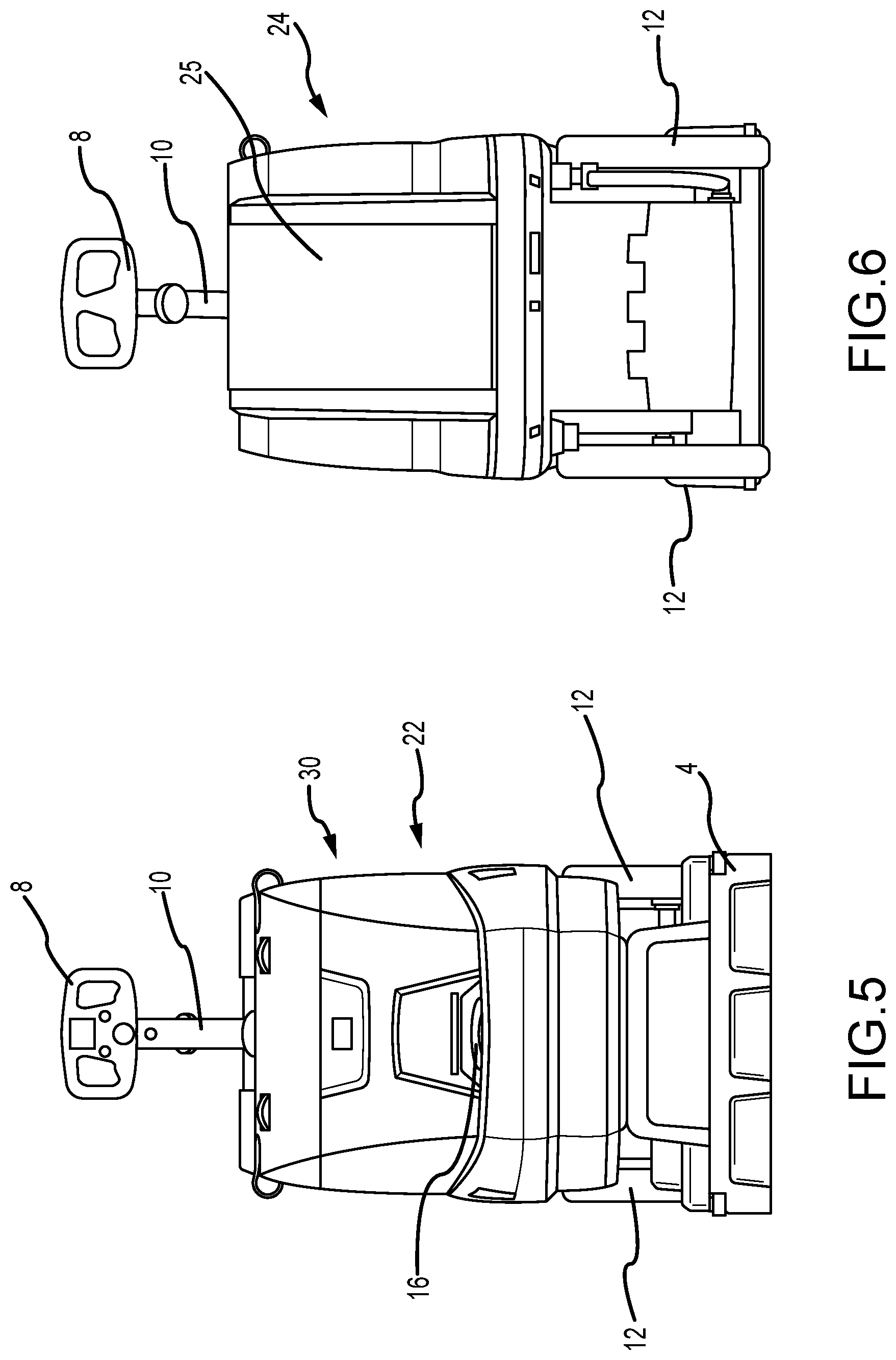
[0035] FIG. 5 is a front elevation view of the cleaning machine according to the embodiment of FIG. 1;
[0036] FIG. 6 is a rear elevation view of the cleaning machine according to the embodiment of FIG. 1;
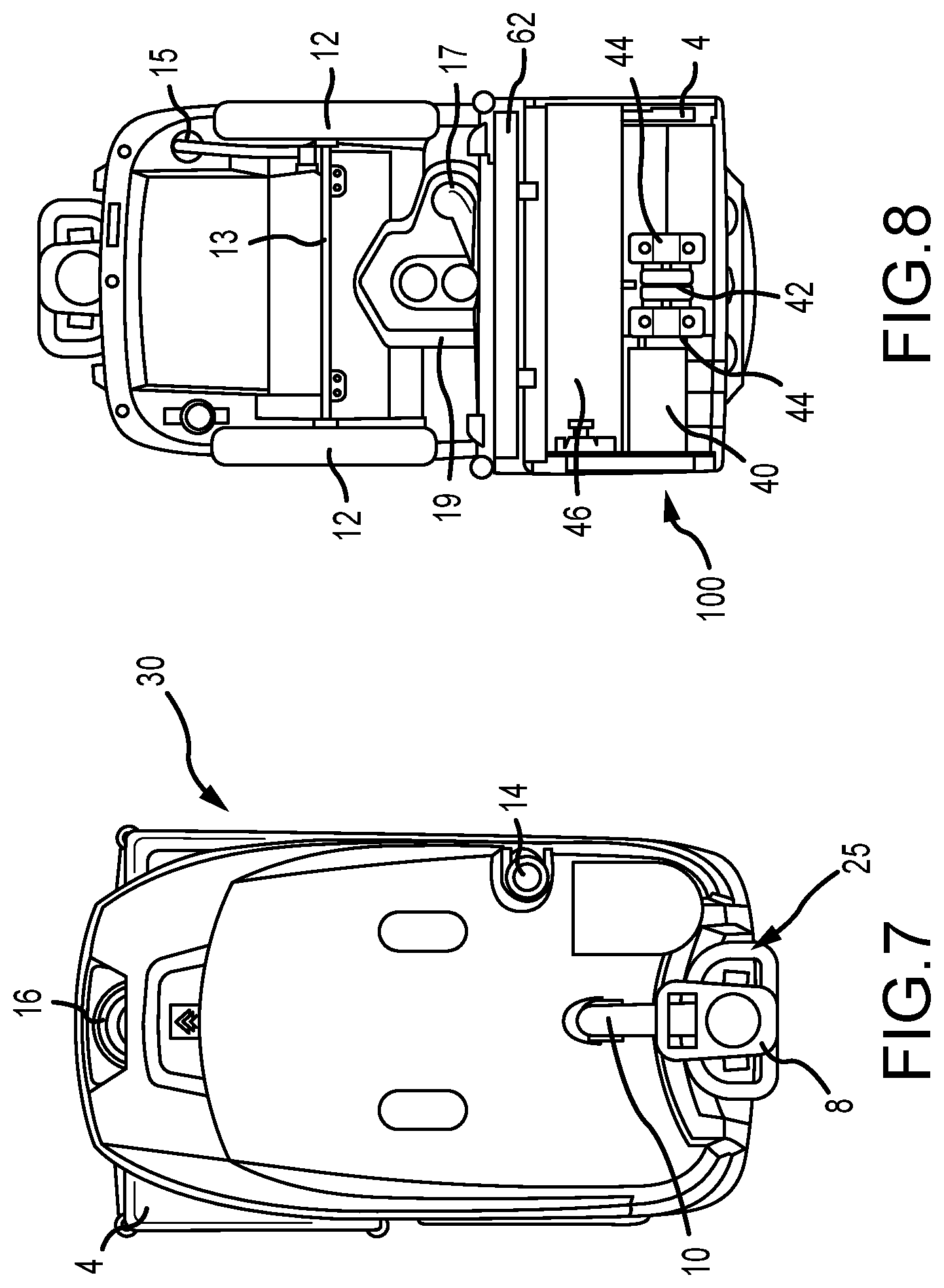
[0037] FIG. 7 is a top plan view of the cleaning machine according to the embodiment of FIG. 1;
[0038] FIG. 8 is a bottom plan view of the cleaning machine according to the embodiment of FIG. 1;
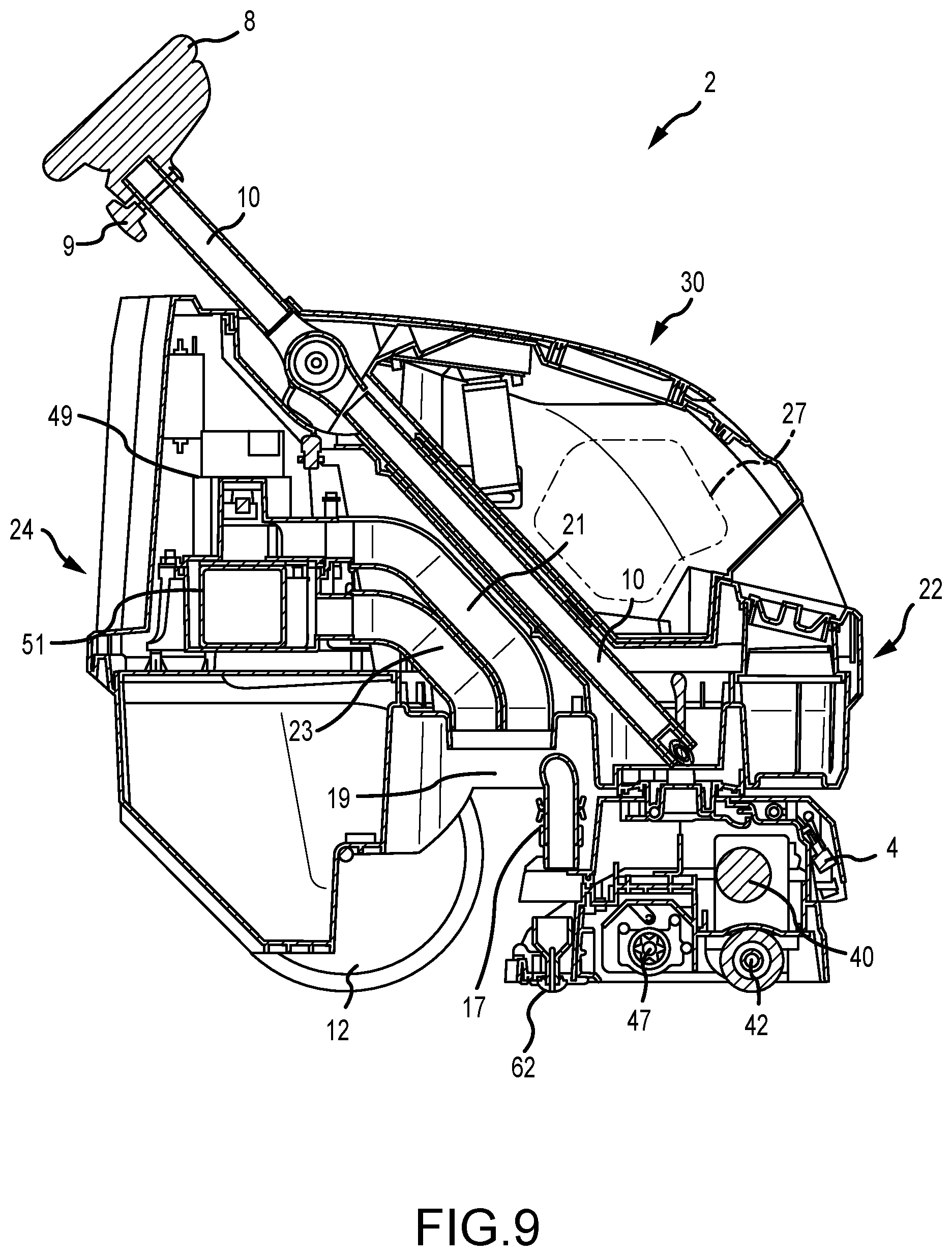
[0039] FIG. 9 is a cross-sectional view of a cleaning machine according to one embodiment of the present disclosure;
[0040] FIG. 10 is a bottom perspective view of a cleaning machine according to one embodiment of the present disclosure; and
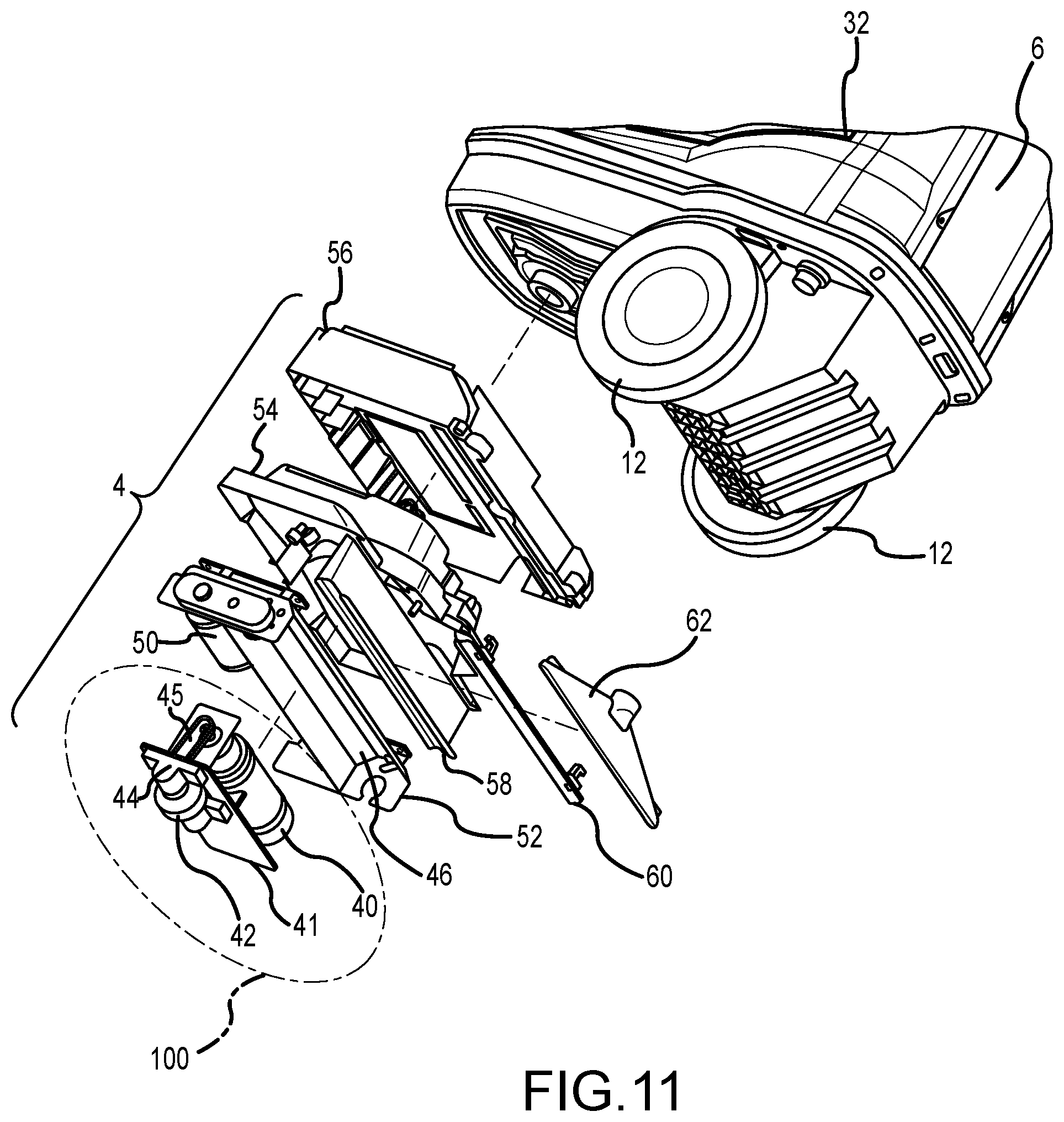
[0041] FIG. 11 is an exploded view of a component of a cleaning machine according to the embodiment of FIG. 10.
DETAILED DESCRIPTION
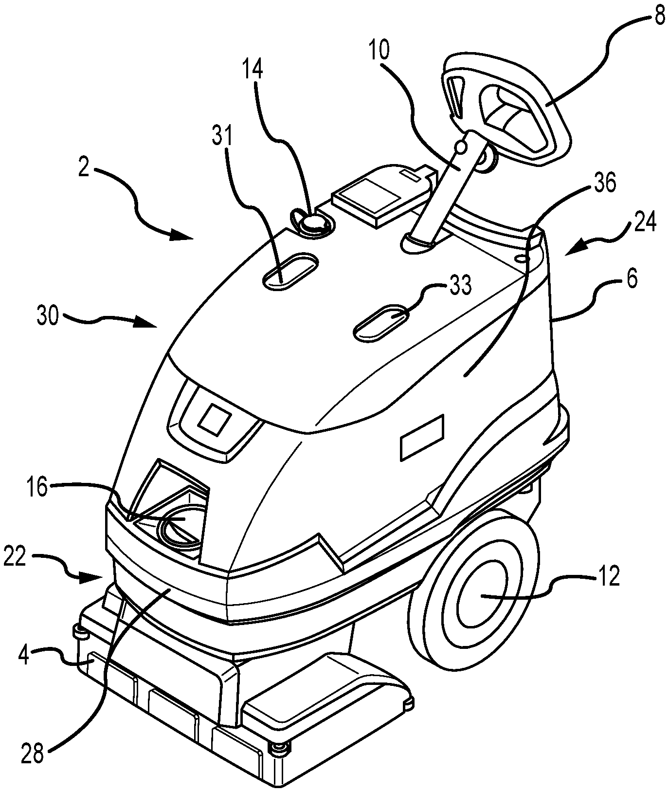
[0042] As shown in FIGS. 1-11, a cleaning machine 2 for cleaning or otherwise treating a floor surface is shown. The embodiment of FIG. 1 includes a chassis 6 with rear wheels 12 and a cleaning deck 4. A steering column 10 is provided that extends from the chassis 6 and comprises a steering mechanism 8, such as a steering wheel.
[0043] In various embodiments, the chassis 6 preferably comprises at least one plastic member. The chassis is contemplated as being comprised of a plurality of injected molded parts. The chassis 6 provides an outer structural framework and generally defines an envelope or area of the cleaning machine 2. In various embodiments, the device 2 comprises an overall height of between approximately 30 and 60 inches, and more preferably of about 45 inches; an overall length of between approximately 20 and 50 inches, and more preferably of about 35 inches; and a width of between approximately 12 and 30 inches, and more preferably of about 18 inches. No limitation with respect to the size or proportions of the device, however, are provided herewith. As shown, the chassis 6 includes a front 22, a rear 24, a front surface 28, an upper surface 30, a left surface 36, and a right surface 38.
[0044] An upper surface 30 of the device preferably comprises a selectively removable lid for accessing internal features of the device 2. In various embodiments, the upper surface of the device 2 comprises a lid that is secured by fasteners and may be completely removed from a remainder of the device. Additionally, and at least as shown in FIG. 1, the upper surface 30 comprises first and second view glasses or observation covers 31, 33. A first observation cover 31 (right side) is provided as a dirty water conduit observation cover, and a second observation cover 33 (left side) is provided as a vacuum conduit observation cover. A solution fill cover 16 is provided, and the solution fill cover comprises a removable cap for selectively inserting a clean fluid into the device 2.
[0045] A recovery drain hose 18 is provided as a drop hose for selectively emptying dirty fluid(s) from the device. As shown, the drain hose 18 comprises a removable cap 14, and is generally recessed within a slot 20 provided in the chassis 6.
[0046] As shown, a pair of rear wheels 12 are operably interconnected to the cleaning machine 2. In preferred embodiments, the rear wheels 12 comprise support wheels for accommodating a weight of the device, but do not comprise powered or drive wheels. In alternative embodiments, however, it is contemplated that at least one of the rear wheels 12 comprises a drive or driven wheel. As shown, the rear wheels 12 are provided behind a center point or center of mass of the device 2, and forward of the rear 24 of the machine. The device of FIG. 1 comprises a walk-behind device wherein a user can steer, control, and/or operate the device while standing and walking behind the device. It should be recognized, however, that various features, devices and systems of the present disclosure are also contemplated for use with other floor cleaning devices including, for example, ride-on or stand-on floor cleaning devices. The rear wheels 12 of various embodiments of the present disclosure comprise solid, molded wheels. In some embodiments, pressurized rubber tires are provided on the wheels 12.
[0047] A cleaning deck 4 is provided and is generally disposed at a forward portion of the device 2. The cleaning deck 4 comprises various features and devices as shown and described herein, and generally comprises means for at least one of cleaning floor or ground surfaces and propelling the device 2. The cleaning deck 4 is operably connected to the steering column 10 and steering mechanism 8, such that an operator may maneuver and/or steer the cleaning deck 4 by manipulating the steering mechanism 8. The cleaning deck 4 is steerable using the steering mechanism 8, and the remainder of the cleaning machine 2 trails behind the cleaning deck 4. In preferred embodiments, and as shown and described in more detail herein, the cleaning deck comprises a propulsion system for the cleaning machine. The chassis 6 may be referred to herein as a "trailer" based on its relationship with a cleaning deck 4 provided at the forward end of the device 2.
[0048] The cleaning deck 4 is preferably pivot-able about a vertical axis and relative to a remainder of the machine 2 according to input from the steering mechanism 8. In various embodiments, steering may be electronically controlled in response to mechanical movement of the steering mechanism 8.
[0049] FIGS. 2-7 provide various views of the embodiment shown in FIG. 1. Various features are shown in FIGS. 2-7 that have already been described and disclosed with respect to FIG. 1, and such description is not reiterated with respect to FIGS. 2-7. A solution tank drain hose 15 is provided to allow a user to optionally drain clean fluid from the device. As shown in FIG. 6, a concave recessed portion 25 is provided to allow space for a user to interact with the device 2.
[0050] FIG. 8 is a bottom plan view of the cleaning machine 2 according to the embodiment of FIGS. 1-7. As shown, the cleaning deck 4 comprises a recess 46 for receiving a cleaning device, such as a brush. The cleaning deck 4 further comprises a drive assembly 100. The drive assembly 100 comprises a motor 40 and a driven wheel 42. The driven wheel 42 is provided at or proximal to a horizontal midline of the cleaning deck 4 and is operable to convey the device 2 and control the speed of the device. The driven wheel 42 is preferably provided forward of the cleaning device recess 46, such that a cleaning device is operable to pick up or clean any debris left behind by the wheel 42. As further shown in FIG. 8, the device 2 comprises a motor 40 for controlling and powering the driven wheel 42. The motor 40 is provided substantially adjacent to the driven wheel 42 and forward of the cleaning device recess 46. As will be recognized by one of skill in the art, the drive assembly 100 comprises a relatively compact device having an electric motor 40.
[0051] As further shown in FIG. 8, the device 2 comprises a vacuum shoe 62 with a vacuum hose or conduit 17 in fluid communication with a spent fluid storage tank provided within the device 2. A vacuum motor assembly is provided within a vacuum housing.
[0052] In various embodiments, and as shown in more detail in FIG. 11, the drive assembly 100 comprises at least one of an electric motor 40, a transmission 45, and bearing(s) 44 in one integrated assembly. The motor 40 is in communication with the driven wheel 42 and is capable of providing power to the wheel 42. Accordingly, the cleaning machine 2 places the drive components, which include the drive assembly 100 with a propel wheel 42 within a leading cleaning deck 4. The chassis 6 is provided as a trailing element relative to the cleaning deck assembly 4.
[0053] FIG. 9 is a cross-sectional elevation view of a cleaning device 2 according to one embodiment of the present disclosure. As shown, the cleaning device 2 comprises at least one propel wheel 42 in a cleaning deck assembly 4. The propel wheel or driven wheel 42 is powered and driven by an electric motor 40. A port or electrical connection is provided to receive a plug and power cord to provide current and electrical power to the device. The depicted embodiment comprises a device that requires a physical connection to an external power source. Alternative embodiments, however, comprise on-board battery units such that a wired, physical connection is not required to operate various features of the device 2. The embodiment of FIG. 9 preferably comprises a controller operable to convert an alternating current to a direct current, and wherein the controller is further operable to provide pulse-width modulation to control a speed of the driven wheel 42, and thus control the speed of the device 2.
[0054] FIG. 9 illustrates a device with a cleaning device recess that is not provided with a cleaning device. The recess comprises a connection 47 for a rotatable cleaning device. The connection 47 comprises a cog or similar device for driving a cleaning device in a rotary manner.
[0055] A vacuum assembly comprising a vacuum housing 49 and a vacuum motor 51 is provided within the device. The vacuum assembly is operable to suction fluid from a floor surface behind a cleaning device in the deck assembly 4. The vacuum assembly comprises wet-dry vacuum features and comprises an intake line 17 and exhaust lines 21, 23. Vacuumed fluid is stored or housed in an on-board collection container 27 that may be selectively emptied via a drain or drop hose (see FIG. 1, item 18). As further shown in FIG. 9, the steering column 10 comprise a release member 9 to allow for selective positioning and adjustment of the steering device 8.
[0056] FIG. 10 is a bottom perspective view of a floor cleaning device 2 according to one embodiment of the present disclosure. The propel wheel 42 is shown in relation to the motor 40. In the depicted embodiment, the propel wheel 42 is mounted to the cleaning deck 4 by first and second bracket members 44, and an axle extends through the propel wheel 42. The drive unit comprises a drive shaft extending from the motor 40 and which is communication with the propel wheel 42 to drive the wheel 42 in forward and reverse at various speeds. As shown, the drive unit and the propel wheel 42 are provided within a recess 39 provided in the deck assembly 4. The recess 39 comprises a void or hollow space to allow for at least portions of the drive assembly to be elevated from a ground surface, and wherein the propel wheel 42 is operable to and capable of contacting the floor or ground surface.
[0057] As further shown in FIG. 10, the device 2 comprises a vacuum with a vacuum shoe 62 having at least one vacuum pick-up orifice trailing the floor cleaning device. In some embodiments, a squeegee is provided on the deck. The deck assembly 4 of FIG. 10 comprises guide wheels or rollers 59 to contact walls and similar objects and guide the direction of the device 2 while minimizing damage to an environment in which the device 2 is operated.
[0058] FIG. 11 is an exploded perspective view of the deck assembly 4 according to the embodiment of FIG. 10. As shown, the deck 4 comprises a plurality of cleaning features and components. Specifically, the deck 4 comprises a driven wheel 42 that is rotatably mounted to first and second bracket members 44 provided on a plate 41. A motor 40 is mounted on the plate and is in communication with the driven wheel 42. Specifically, a drive shaft of the drive unit 40 communicates with an axle of the wheel 42 via a transmission member 45 which is contemplated as comprising a belt, roller chain, or similar device. The present disclosure also contemplates a direct-drive assembly between a motor drive shaft and a wheel. The deck assembly 4 further comprises a motor and brush mount 52 which is operable to receive and support a cleaning brush (not shown in FIG. 11) and a dedicated brush motor 50. The cleaning brush preferably comprises a replaceable, rotary brush that is operable to removed for cleaning, repair and replacement. A shroud 54 and a weighted member 56 are also provided and are stacked when the deck 4 is in an assembled state (see FIG. 10, for example). At least one of the shroud and the weighted member 54, 56 are operable to receive and house electronics including, but not limited to, wiring, circuit boards, and controllers. The deck 4 further comprises a debris tray 58, a vacuum glide 60, and a vacuum shoe 62. The vacuum glide 60 and vacuum shoe 62 preferably comprise trailing features that are provided behind the cleaning brush (relative to a forward direction of travel of the device 2). The debris tray 58 is preferably removable for cleaning.
[0059] As shown in FIGS. 9-11, a motor 40 is provided in communication with a driven wheel 42 for providing locomotion to the device. In the depicted embodiment, the motor 40 is provided vertically above the wheel 42. Although various arrangements are contemplated, certain embodiments of the present disclosure provide that at least a drive axle of the motor 40 is provided vertically above an axle of the wheel 42. It is also contemplated that more than one driven wheel is provided.
[0060] In some embodiments, a propel or driven wheel is provided that is adjustable in at least a vertical direction. Specifically, various embodiments of the present disclosure comprise a powered wheel for driving and controlling the speed of a floor cleaning device as shown and described herein, and wherein the wheel comprises vertical adjustability. A vertical position, and a position of the wheel relative to a flooring or ground surface is adjustable to accommodate for different floor surface conditions and, in at least some embodiments, allows a user to lift or remove a propel wheel from the floor or ground surface. Such embodiments allow a user the option to render the wheel inoperable for locomotive purposes, and rely on a rotary brush alone for such purposes. In some embodiments, it is contemplated that a drive assembly 100 of the present disclosure is pivotable such that a vertical position of the drive wheel is adjustable.
[0061] Various features and embodiments of floor cleaners are provided herein. It will be recognized, however, that various features are not necessarily specific to certain embodiments and may be provided on any one or more embodiments. The present disclosure and embodiments provided herein are not mutually exclusive and may be combined, substituted, and omitted. The scope of the invention(s) provided herein is thus not limited to any particular embodiment, drawing, or particular arrangement of features.
[0062] While various embodiments of the present disclosure have been described in detail, it is apparent that modifications and alterations of those embodiments will occur to those skilled in the art. However, it is to be expressly understood that such modifications and alterations are within the scope and spirit of the present disclosure. Further, the invention(s) described herein are capable of other embodiments and of being practiced or of being carried out in various ways. In addition, it is to be understood that the phraseology and terminology used herein is for the purposes of description and should not be regarded as limiting. The use of "including," "comprising," or "adding" and variations thereof herein are meant to encompass the items listed thereafter and equivalents thereof, as well as, additional items.
* * * * *
D00000
D00001
D00002
D00003
D00004
D00005
D00006
D00007
XML
uspto.report is an independent third-party trademark research tool that is not affiliated, endorsed, or sponsored by the United States Patent and Trademark Office (USPTO) or any other governmental organization. The information provided by uspto.report is based on publicly available data at the time of writing and is intended for informational purposes only.
While we strive to provide accurate and up-to-date information, we do not guarantee the accuracy, completeness, reliability, or suitability of the information displayed on this site. The use of this site is at your own risk. Any reliance you place on such information is therefore strictly at your own risk.
All official trademark data, including owner information, should be verified by visiting the official USPTO website at www.uspto.gov. This site is not intended to replace professional legal advice and should not be used as a substitute for consulting with a legal professional who is knowledgeable about trademark law.