Hand-held Article-placing Rack
Tsao; Chung-Piao
U.S. patent application number 16/355842 was filed with the patent office on 2020-04-23 for hand-held article-placing rack. The applicant listed for this patent is E-PACKAGE CREATION & SOLUTION MANUFACTURING CORP.. Invention is credited to Chung-Piao Tsao.
| Application Number | 20200121106 16/355842 |
| Document ID | / |
| Family ID | 70279255 |
| Filed Date | 2020-04-23 |


| United States Patent Application | 20200121106 |
| Kind Code | A1 |
| Tsao; Chung-Piao | April 23, 2020 |
HAND-HELD ARTICLE-PLACING RACK
Abstract
A hand-held article-placing rack, which comprises: a first article-placing unit having a first accommodating space; a second article-placing unit having a second accommodating space; and a connecting piece which both ends respectively combined with the first article-placing unit and the second article-placing unit; wherein the first article-placing unit and the second article-placing unit are ring-shape to provide two beverage cups to insert and place; or, the first article-placing unit or the second article-placing unit is a polygon shape and has a bottom portion; so as to provide the first article-placing unit or the second article-placing unit to contain and carry food.
| Inventors: | Tsao; Chung-Piao; (Taipei City, TW) | ||||||||||
| Applicant: |
|
||||||||||
|---|---|---|---|---|---|---|---|---|---|---|---|
| Family ID: | 70279255 | ||||||||||
| Appl. No.: | 16/355842 | ||||||||||
| Filed: | March 18, 2019 |
Related U.S. Patent Documents
| Application Number | Filing Date | Patent Number | ||
|---|---|---|---|---|
| 16168802 | Oct 23, 2018 | |||
| 16355842 | ||||
| Current U.S. Class: | 1/1 |
| Current CPC Class: | A47G 23/0208 20130101 |
| International Class: | A47G 23/02 20060101 A47G023/02 |
Claims
1: A hand-held article-placing rack comprising: a first foldable article-placing unit having a first accommodating space, wherein a first opening passes from a top of the first foldable article-placing unit in a direction, wherein the first foldable article-placing unit has a first edge at a top of the first opening; a second foldable article-placing unit having a second accommodating space, wherein a second opening passes from a top of the second foldable article-placing unit in the direction, wherein the second foldable article-placing unit has a second edge at a top of the second opening; and a neck portion between the first and second foldable article-placing units, wherein the neck portion joins the first and second edges, the neck portion has a length extending from the first edge to the second edge and a width vertical to the length, wherein the width of the neck portion is smaller than a width of the first foldable article-placing unit parallel to the width of the neck portion and smaller than a width of the second foldable article-placing unit parallel to the M of the neck portion, wherein no connecting piece is between a sidewall of the first foldable article-placing unit under the first edge and a sidewall of the second foldable article-placing unit under the second edge to connect the sidewall of the first foldable article-placing unit with the sidewall of the second foldable article-placing unit.
2: The hand-held article-placing rack of claim 1, wherein the first foldable article-placing unit has two first folding lines opposite to each other.
3: The hand-held article-placing rack of claim 2, wherein each of the two first folding lines extends in the direction.
4. (canceled)
5: The hand-held article-placing rack of claim 1, wherein the first foldable article-placing unit has a circular sidewall.
6: The hand-held article-placing rack of claim 2, wherein the second foldable article-placing unit has two second folding lines opposite to each other.
7: The hand-held article-placing rack of claim 3, wherein the second foldable article-placing unit has two second folding lines opposite to each other in the direction.
8. (canceled)
9: The hand-held article-placing rack of claim 6, wherein the second foldable article-placing unit has a third folding line at a bottom of the second foldable article-placing unit.
10: The hand-held article-placing rack of claim 1, wherein the second foldable article-placing unit has a folding line at a bottom of the second foldable article-placing unit.
11: The hand-held article-placing rack of claim 1, wherein the first foldable article-placing unit has a circular sidewall, and the second foldable article-placing unit has a circular sidewall.
12: The hand-held article-placing rack of claim 1, wherein the first foldable article-placing unit has a circular sidewall, wherein the second opening at the top of the second article placing unit has a shape with a first width and a second width vertical to the first width, wherein the first width is greater than the second width.
13: The hand-held article-placing rack of claim 1, wherein an opening passes from a top of the second article placing unit, wherein the second opening at the top of the second article placing unit has a shape with a first width and a second width vertical to the first width, wherein the first width is greater than the second width.
14-20: (canceled)
Description
CROSS-REFERENCE
[0001] This is a division of the co-pending patent application Ser. No. 16/168,802 filed Oct. 23, 2018.
(a) TECHNICAL FIELD OF THE INVENTION
[0002] The present invention relates to an article-placing rack, and especially relates to a hand-held article-placing rack that can hold two cups of beverages or one cup of beverage and a box of food.
(b) DESCRIPTION OF THE PRIOR ART
[0003] With the increasing awareness of environmental protection, the use of cartons to contain and carry the food or articles has long been widely adopted and valued by modern people; in particular, the recycled paper can be used to make cartons.
[0004] By this kind of reusing the paper resources, which can avoid the problem of waste pollution caused by the use of styrofoam, plastic or other material that cannot be recycled.
[0005] The conventional carton structure has only a single use purpose, for example, only using a carton for containing and carrying food or articles.
[0006] However, with the prevalence of various types of beverages, most consumers hold a beverage container in their hands; if consumers take a food carton in one hand and take the beverage container in the other hand, it will cause consumers very inconvenient. Therefore, in order to make it convenient for the consumer to carry the food carton or the beverage container, the merchants use the plastic bag to contain and carry the food carton or the beverage container. As a result, when the plastic bags are used in large quantities, the caused pollution to the environment is relatively increased.
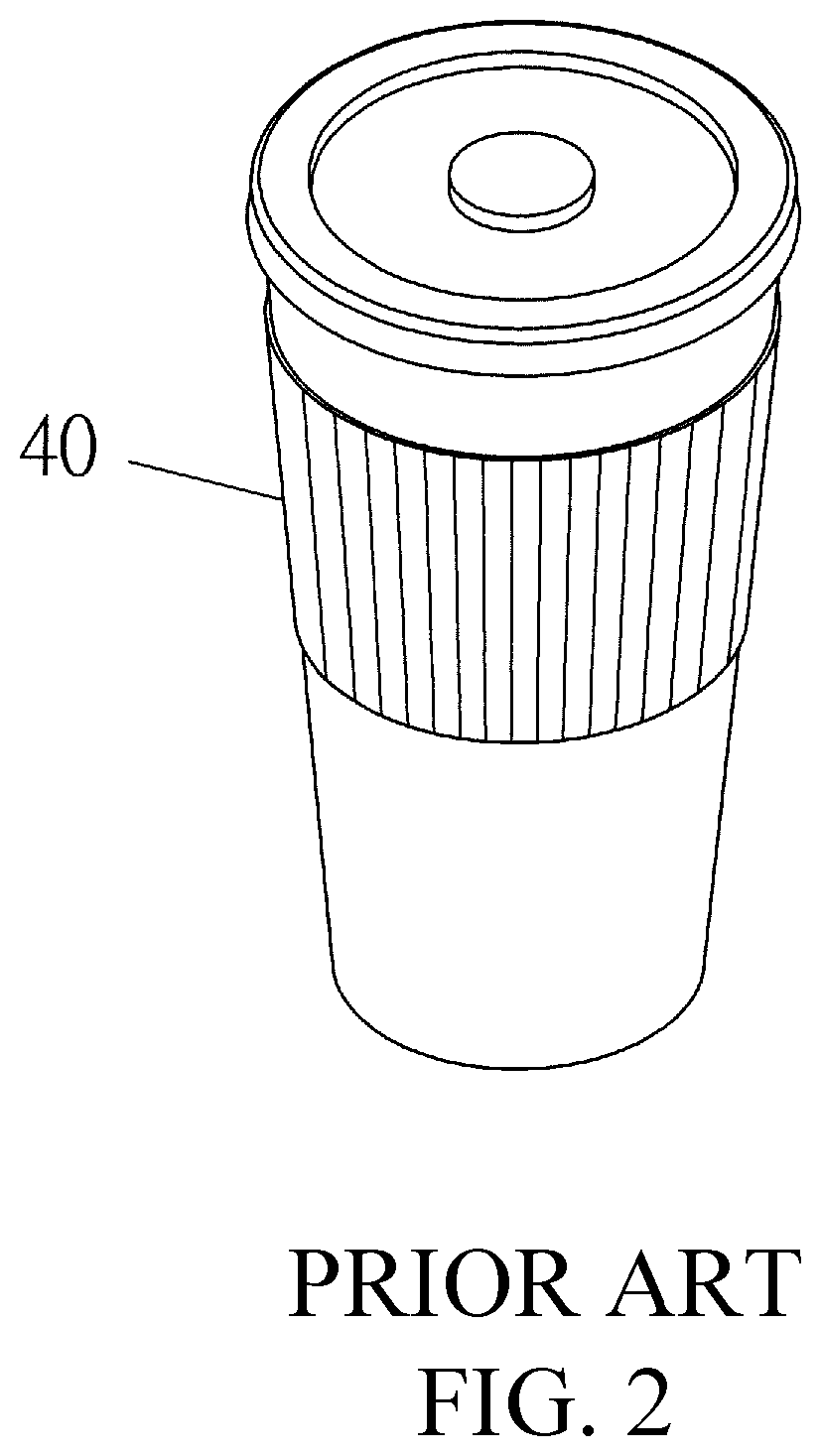
[0007] Please refer to FIG. 1 and FIG. 2, for the conventional folding heat insulation sleeve 40, which is provided to sleeve and set on the hot drink cup to achieve the anti-scalding function. However, the conventional folding insulated sleeve can only carry a single cup and cannot have other article-carrying function, so there is still a necessity for improvement.
SUMMARY OF THE INVENTION
[0008] In view of the above-mentioned shortcomings, the hand-held article-placing rack of the present invention comprises a first article-placing unit having a first accommodating space; a second article-placing unit having a second accommodating space; and a connecting piece which both ends respectively combined with the first article-placing unit and the second article-placing unit; wherein the first article-placing unit and the second article-placing unit are ring-shape to provide two beverage cups to insert and place; or, the first article-placing unit or the second article-placing unit is a polygon shape and has a bottom portion; so as to provide the first article-placing unit or the second article-placing unit to contain and carry food.
BRIEF DESCRIPTION OF THE DRAWINGS
[0009] FIG. 1 is a folding plane schematic diagram of the of the conventional heat insulation sleeve.
[0010] FIG. 2 is a folding usage schematic diagram of the heat insulation sleeve continuing FIG. 1.
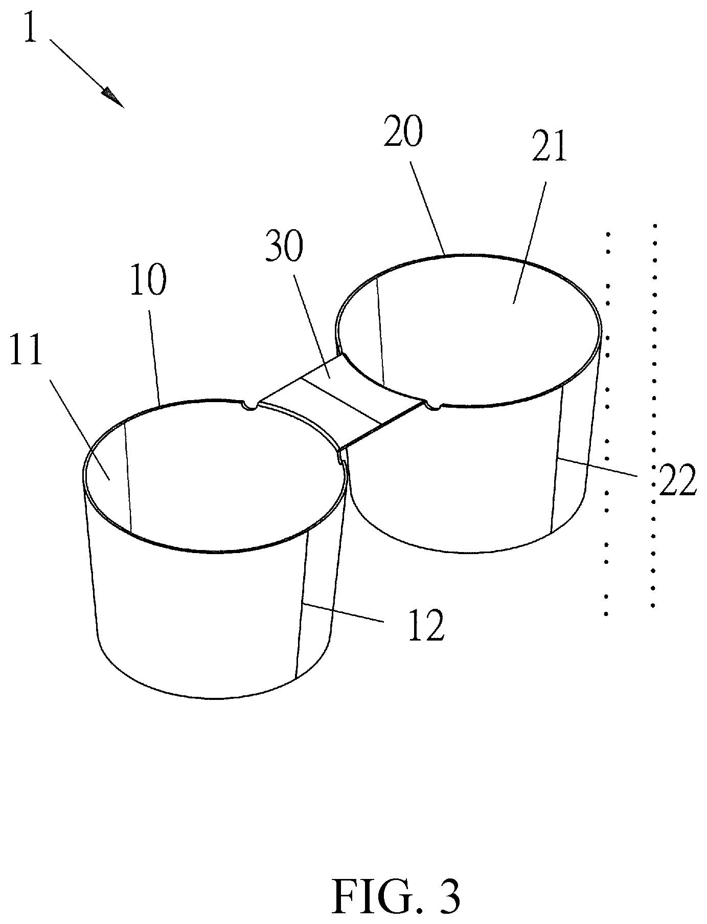
[0011] FIG. 3 is a stereoscopic appearance diagram of the first embodiment of the present invention.
[0012] FIG. 4 is a usage state schematic diagram continuing FIG. 3.
[0013] FIG. 5 is a stereoscopic appearance diagram of the second embodiment of the present invention.
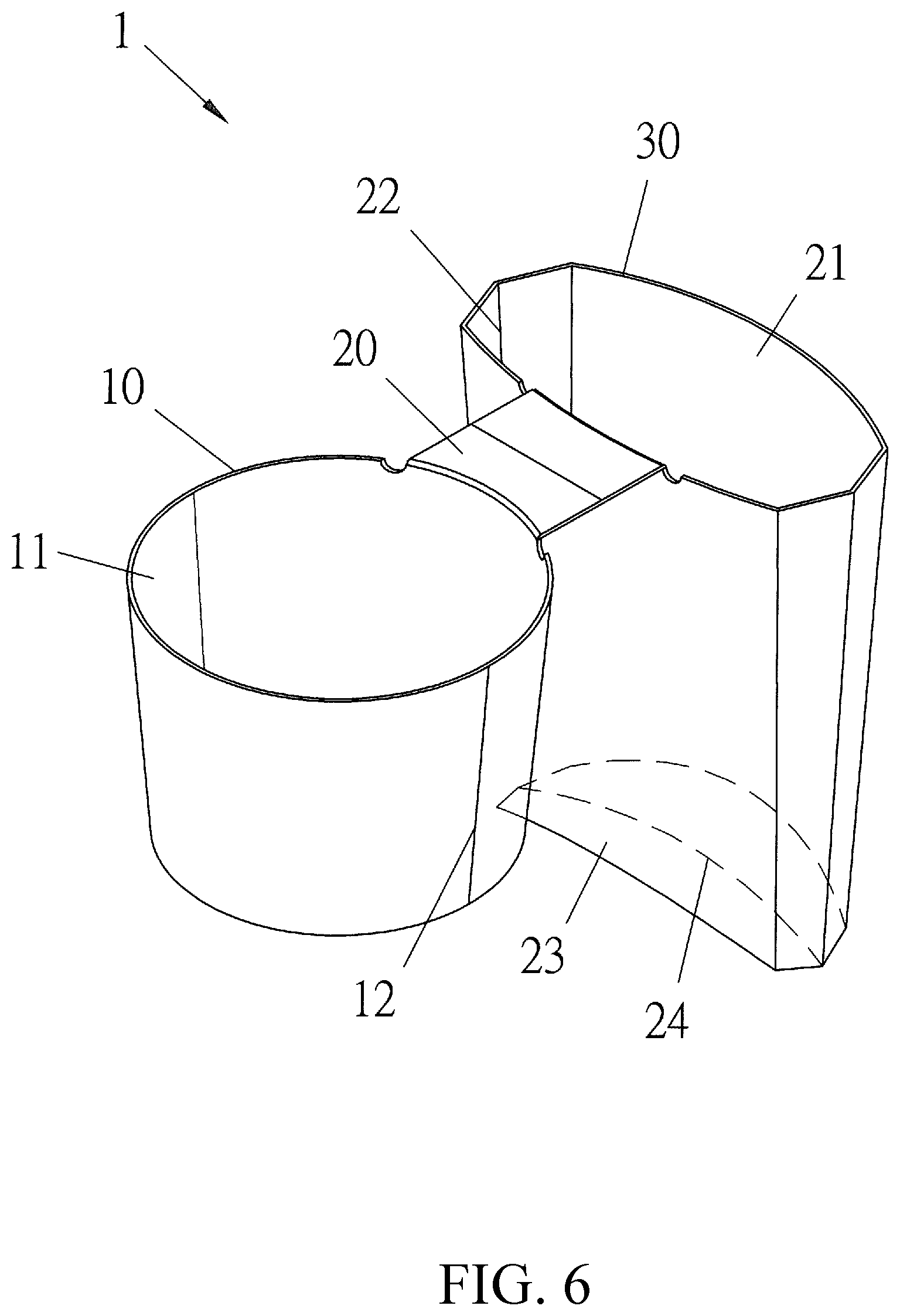
[0014] FIG. 6 is a stereoscopic appearance diagram of the third embodiment of the present invention.
DETAILED DESCRIPTION OF THE PREFERRED EMBODIMENTS
[0015] The following descriptions are exemplary embodiments only, and are not intended to limit the scope, applicability or configuration of the invention in any way. Rather, the following detailed description provides a convenient illustration for implementing exemplary embodiments of the invention. Various changes to the described embodiments may be made in the function and arrangement of the elements described without departing from the scope of the invention as set forth in the appended claims.
[0016] The foregoing and other aspects, features, and utilities of the present invention will be best understood from the following detailed description of the preferred embodiments when read in conjunction with the accompanying drawings.
[0017] Please refer to FIG. 3, a hand-held article-placing rack 1 of the first embodiment of the present invention comprises a first article-placing unit 10, a second article-placing unit 20, and a connecting piece 30. The components are respectively described as follows:
[0018] The first article-placing unit 10 has a first accommodating space 11.
[0019] The second article-placing unit 20 has a second accommodating space 21, wherein the first article-placing unit 10 and the second article-placing unit 20 are ring-shape.
[0020] Two first folding lines 12 and two second folding lines 22 are respectively set on two opposite sides of the first article-placing unit 10 and the second article-placing unit 20, and the first article-placing unit 10 and the second article-placing unit 20 can be folded into a flat shape along each of the first folding line 12 and each of the second folding lines 22 for being easy storaged. Both ends of the connecting piece 30 are respectively combined with the first article-placing unit 11 and the second article-placing unit 21.
[0021] Please refer to FIG. 4, the first accommodating space 11 and the second accommodating space 21 respectively provide to insert and place a beverage cup; when the user holds the first article-placing unit 10 in one hand, the connecting piece 30 will naturally abut against the hand, and the second article-placing unit 20 will abut against the back of the hand, whereby the two cups of beverage can be stably held.
[0022] Please refer to FIG. 5 and FIG. 6, which are the second embodiment of the present invention; the main structure is the same as that of the first embodiment, so the same places will not be further described again. In this embodiment, the first article-placing unit 10 is a ring shape, and the second article-placing unit 20 is a square, rectangle, or polygon shape; in FIG. 5 and FIG. 6, the second article-placing unit 20 is a shape of a rectangular box and a French fries box; wherein the second article-placing unit 20 has a bottom portion 23; and the bottom portion 23 has at least one third folding line 24, whereby the second article-placing unit 20 can be folded into a flat shape.
* * * * *
D00000
D00001
D00002
D00003
D00004
D00005
D00006
XML
uspto.report is an independent third-party trademark research tool that is not affiliated, endorsed, or sponsored by the United States Patent and Trademark Office (USPTO) or any other governmental organization. The information provided by uspto.report is based on publicly available data at the time of writing and is intended for informational purposes only.
While we strive to provide accurate and up-to-date information, we do not guarantee the accuracy, completeness, reliability, or suitability of the information displayed on this site. The use of this site is at your own risk. Any reliance you place on such information is therefore strictly at your own risk.
All official trademark data, including owner information, should be verified by visiting the official USPTO website at www.uspto.gov. This site is not intended to replace professional legal advice and should not be used as a substitute for consulting with a legal professional who is knowledgeable about trademark law.