Safety Selectors
Zung; Michael ; et al.
U.S. patent application number 16/601037 was filed with the patent office on 2020-04-16 for safety selectors. The applicant listed for this patent is Safe Operator Solutions LLC. Invention is credited to John Mark Cobb, Michael Zung.
| Application Number | 20200116448 16/601037 |
| Document ID | / |
| Family ID | 70159354 |
| Filed Date | 2020-04-16 |


| United States Patent Application | 20200116448 |
| Kind Code | A1 |
| Zung; Michael ; et al. | April 16, 2020 |
SAFETY SELECTORS
Abstract
Embodiments of safety selectors are disclosed. A safety selector can include a body configured to engage an internal safety mechanisms of a firearm. The safety selector can further include a first arm and a second arm that extend from the body. The first arm and the second arm can be oriented such that a non-zero angle exists between a first axis associated with the first arm and a second axis associated with the second arm.
| Inventors: | Zung; Michael; (San Carlos, CA) ; Cobb; John Mark; (Carrollton, GA) | ||||||||||
| Applicant: |
|
||||||||||
|---|---|---|---|---|---|---|---|---|---|---|---|
| Family ID: | 70159354 | ||||||||||
| Appl. No.: | 16/601037 | ||||||||||
| Filed: | October 14, 2019 |
Related U.S. Patent Documents
| Application Number | Filing Date | Patent Number | ||
|---|---|---|---|---|
| 62746317 | Oct 16, 2018 | |||
| Current U.S. Class: | 1/1 |
| Current CPC Class: | F41A 17/74 20130101; F41A 19/46 20130101; F41A 17/00 20130101; F41A 17/02 20130101; F41A 17/46 20130101; F41A 35/06 20130101; F41A 17/56 20130101; F41A 19/12 20130101; F41A 19/10 20130101 |
| International Class: | F41A 17/46 20060101 F41A017/46; F41A 17/02 20060101 F41A017/02; F41A 19/10 20060101 F41A019/10; F41A 19/46 20060101 F41A019/46; F41A 19/12 20060101 F41A019/12; F41A 35/06 20060101 F41A035/06; F41A 17/56 20060101 F41A017/56; F41A 17/74 20060101 F41A017/74 |
Claims
1. An apparatus, comprising: a safety selector body comprising a first end and a second end, the safety selector body being configured to engage an internal safety mechanism of a firearm, wherein a longitudinal axis of the safety selector body extends through the first end and the second end of the safety selector body; a first arm extending from the first end of the safety selector body, the first arm comprising a first proximal end and a first distal end relative to the first end of the safety selector body, wherein a first arm axis extends through the first proximal end and the first distal end of the first arm, the first arm axis being perpendicular to the longitudinal axis of the safety selector body; and a second arm extending from the second end of the safety selector body, the second arm comprising a second proximal end and a second distal end relative to the second end of the safety selector body, wherein a second arm axis extends through the second proximal end and the second distal end of the second arm, the second arm axis being perpendicular to the longitudinal axis of the safety selector body, the second arm being oriented relative to the first arm such that a non-zero angle exists between the first arm axis and the second arm axis.
2. The apparatus of claim 1, wherein the first arm and the second arm are equal in length.
3. The apparatus of claim 1, wherein at least one of the first arm or the second arm is separable from at least a portion of the safety selector body.
4. The apparatus of claim 1, wherein at least one of the first arm or the second arm comprises an exterior surface that is not perpendicular to the longitudinal axis of the safety selector body.
5. The apparatus of claim 1, wherein at least one of the first arm or the second arm comprises a texturization.
6. An apparatus, comprising: a safety selector body configured to engage an internal safety mechanism of a firearm; a first arm extending from the safety selector body; and a second arm extending from the safety selector body, the second arm being oriented relative to the first arm such that a non-zero angle exists between a first arm axis associated with the first arm and a second arm axis associated with the second arm.
7. The apparatus of claim 6, wherein the first arm and the second arm are equal in length.
8. The apparatus of claim 6, wherein the non-zero angle is greater than 15 degrees and less than 60 degrees.
9. The apparatus of claim 6, wherein the non-zero angle is greater than 25 degrees and less than 60 degrees.
10. The apparatus of claim 6, wherein the non-zero angle is greater than 35 degrees and less than 55 degrees.
11. The apparatus of claim 6, wherein the non-zero angle is greater than 40 degrees and less than 50 degrees.
12. The apparatus of claim 6, wherein the first arm axis is perpendicular to a longitudinal axis of the safety selector body.
13. The apparatus of claim 12, wherein the second arm axis is perpendicular to the longitudinal axis of the safety selector body.
14. The apparatus of claim 6, wherein the first arm comprises a first arm exterior surface that is not perpendicular to a longitudinal axis of the safety selector body.
15. The apparatus of claim 14, wherein the second arm comprises a second arm exterior surface that is not perpendicular to the longitudinal axis of the safety selector body.
16. The apparatus of claim 6, wherein at least one of the first arm or the second arm is separable from at least a portion of the safety selector body.
17. The apparatus of claim 6, wherein at least one of the first arm or the second arm comprises a texturized surface.
18. A method, comprising: moving a first arm of a safety selector to cause a firearm to enter a fire state, the first arm of the safety selector being located at a first external side of the firearm; and moving a second arm of the safety selector to cause the firearm to change from the fire state to a safe state, the second arm being located at a second external side of the firearm, the second arm being oriented relative to the first arm such that a non-zero angle exists between a first arm axis associated with the first arm and a second arm axis associated with the second arm.
19. The method of claim 18, wherein the first arm and the second arm are equal in length.
20. The method of claim 18, wherein the first arm is perpendicular to a safety selector body that extends between the first arm and the second arm.
21. The method of claim 20, wherein the second arm is perpendicular to the safety selector body.
22. The method of claim 18, further comprising attaching at least one of the first arm or the second arm of the safety selector to a safety selector body, wherein at least a portion of the safety selector body is internal to the firearm.
Description
CROSS-REFERENCE TO RELATED CASES
[0001] This application is a non-provisional application of, and claims priority to, U.S. Provisional Application No. 62/746,317, entitled "SAFETY SELECTORS," filed on Oct. 16, 2018, the entirety of which is incorporated by reference herein for all purposes.
BACKGROUND
[0002] For various rifles, such as AR-15 rifles, the safety selector can be switched between the "safe" (3 o'clock) and "fire" (6 o'clock) positions by manipulating an arm of the safety selector on one side of the firearm. Firearms and firearm accessories manufacturers have introduced ambidextrous safety selectors that comprise safety selector arms on both sides of the firearm. Ambidextrous safety selectors can give the user the option to shoot either right-handed or left-handed by having an arm for the safety selector present on both sides of the firearm.
BRIEF DESCRIPTION OF THE DRAWINGS
[0003] Many aspects of the present disclosure can be better understood with reference to the following drawings. The components in the drawings are not necessarily to scale, with emphasis instead being placed upon clearly illustrating the principles of the disclosure. Moreover, in the drawings, like reference numerals designate corresponding parts throughout the several views.
[0004] FIGS. 1A-1B show various views of an example of a safety selector for a firearm according to various embodiments of the present disclosure.
[0005] FIG. 2 shows the safety selector of FIGS. 1A-1B in a fire position according to various embodiments of the present disclosure.
[0006] FIG. 3 shows the safety selector of FIGS. 1A-1B in a safe position according to various embodiments of the present disclosure.
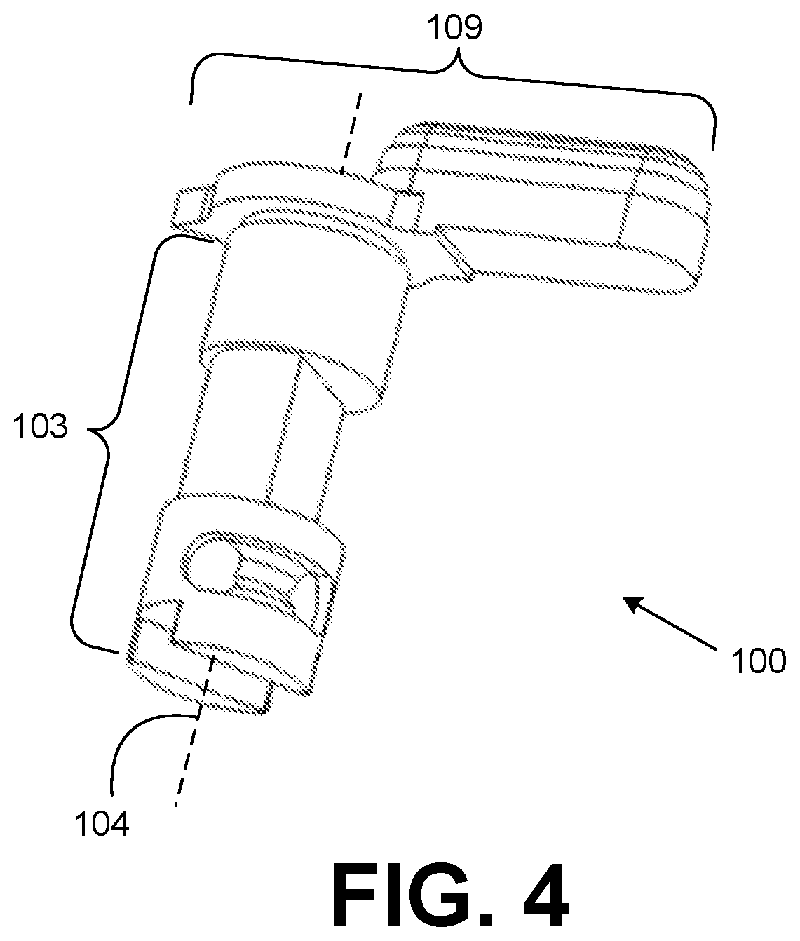
[0007] FIG. 4 shows the safety selector of FIGS. 1A-1B with one of the arms removed.
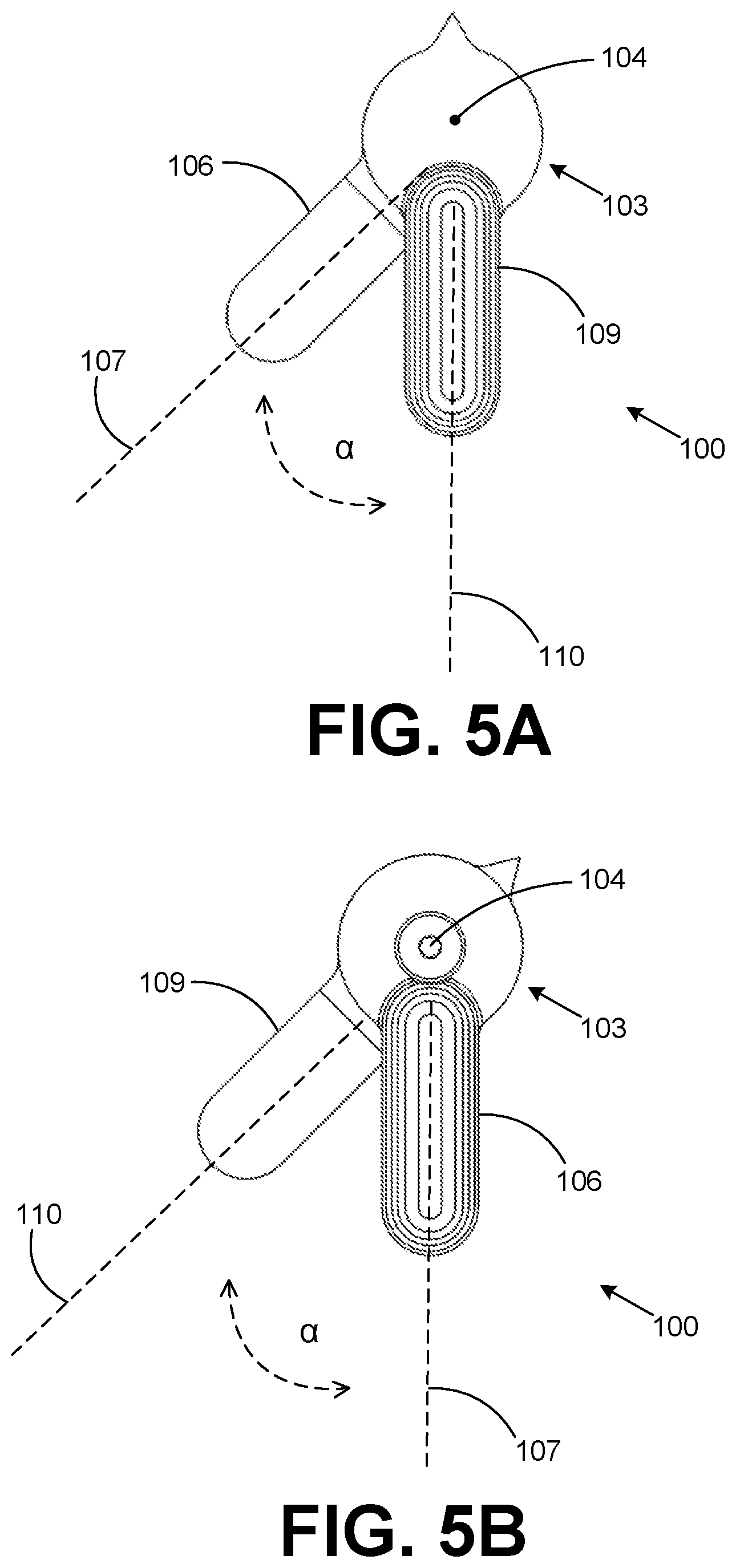
[0008] FIGS. 5A-5B show side view of the safety selector of FIGS. 1A-1B.
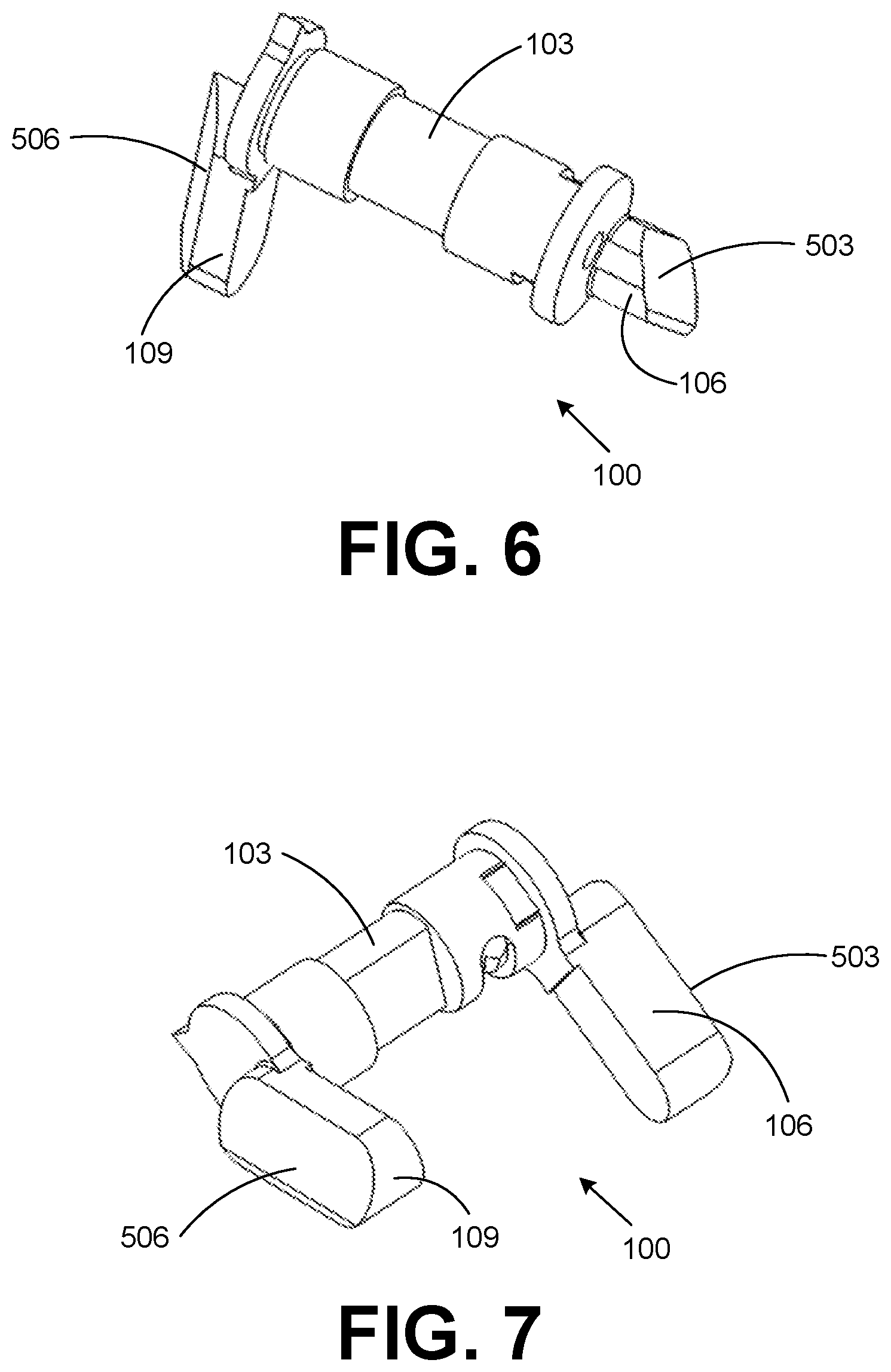
[0009] FIGS. 6-7 show another example of a safety selector for a firearm according to various embodiments of the present disclosure.
DETAILED DESCRIPTION
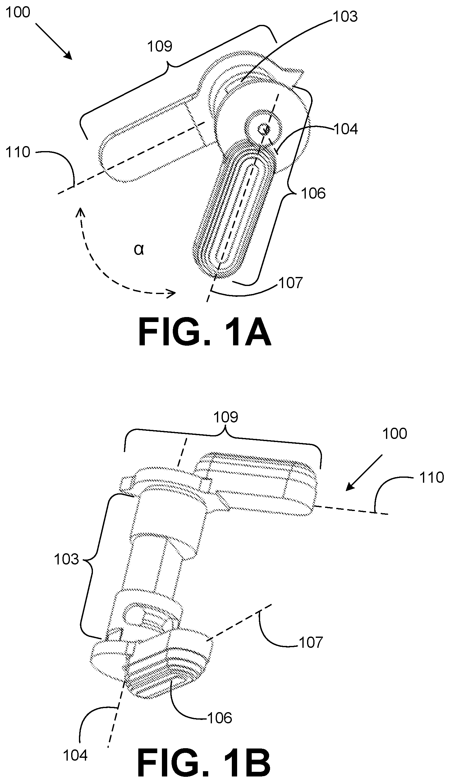
[0010] The present disclosure relates to safety selectors for firearms. With reference to FIGS. 1A-1B, shown is an example of safety selector 100 according to various embodiments of the present disclosure. The safety selector 100 shown in FIGS. 1A-1B is configured for use with an AR-15 rifle (not shown). However, safety selectors 100 in accordance with the present disclosure can be used with other types of firearms. Moreover, the safety selector 100 shown in FIGS. 1A-1B is configured for a right-handed user. However, as can be appreciated, the safety selector 100 can be configured for left-handed users in alternative embodiments.
[0011] As shown in FIGS. 1A-1B, the safety selector 100 can include a body 103, a first arm 106, a second arm 109, and/or other features. The body 103 can have a generally cylindrical shape with a longitudinal axis 104 that extends through the ends of the body 103. When the safety selector 100 is installed in a firearm, the body 103 of the safety selector 100 can reside internal to the firearm. By rotating the safety selector 100 using the first arm 106 and/or second arm 109, the body 103 can engage and disengage the internal safety mechanism of the firearm in order to cause the firearm to selectively enter a safe state or a fire state.
[0012] The first arm 106 and the second arm 109 can be the portions of the safety selector 100 that are configured to be contacted and manipulated by a user. Accordingly, when the safety selector 100 is installed in the firearm, the first arm 106 and the second arm 109 can be located proximate to the external sides of the firearm. In this location, a user can push or pull the first arm 106 and/or second arm 109 using a finger and/or thumb to rotate the safety selector 100 and selectively cause the firearm to enter a safe or fire state. For a right-handed firearm, the second arm 109 can be the primary selector arm for the safety selector 100 (and manipulated using a thumb), and the first arm 106 can be the secondary selector arm (and manipulated with a finger), which may also be referred to as the "ambidextrous arm."
[0013] The first arm 106 can be attached to the body 103 of the safety selector 100 such that the first arm 106 is generally perpendicular to the longitudinal axis 104 of the body 103. For example, a first arm axis 107 extending from a proximal end to a distal end of the first arm 106 relative to the body 103 can be generally perpendicular to the longitudinal axis 104 of the body 103.
[0014] Similarly, the second arm 109 can be attached to the body 103 of the safety selector 100 such that the second arm 109 is generally perpendicular to the longitudinal axis 104 of the body 103. For example, a second arm axis 110 extending from a proximal end to a distal end of the first arm 106 relative to the body 103 can be generally perpendicular to the longitudinal axis 104 of the body 103.
[0015] As shown in FIGS. 1A-1B, the first arm 106 and second arm 109 can be located in planes where they operate and move generally parallel to each other. Additionally, the interior sides of the first arm 106 and second arm 109, which face the firearm when the safety selector 100 is installed, can be generally flat and oriented so that the first arm 106 and second arm 109 are able to freely rotate so that the safety selector 100 can rotate between the fire and safe positions when manipulated by a user.
[0016] As depicted in FIG. 1A-1B, the first arm 106 and second arm 109 can be oriented relative to each other such that there is a non-zero angle .alpha. between the first arm axis 107 of the first arm 106 and the second arm axis 110 of the second arm 109. In one embodiment, the angle .alpha. between the first arm axis 107 of the first arm 106 and the second arm axis 110 of the second arm 109 can be about 15 degrees. In another embodiment, the angle .alpha. between the first arm axis 107 of the first arm 106 and the second arm axis 110 of the second arm 109 can be about 20 degrees. In another embodiment, the angle .alpha. between the first arm axis 107 of the first arm 106 and the second arm axis 110 of the second arm 109 can be about 25 degrees. In another embodiment, the angle .alpha. between the first arm axis 107 of the first arm 106 and the second arm axis 110 of the second arm 109 can be about 30 degrees. In another embodiment, the angle .alpha. between the first arm axis 107 of the first arm 106 and the second arm axis 110 of the second arm 109 can be about 35 degrees. In another embodiment, the angle .alpha. between the first arm axis 107 of the first arm 106 and the second arm axis 110 of the second arm 109 can be about 40 degrees. In another embodiment, the angle .alpha. between the first arm axis 107 of the first arm 106 and the second arm axis 110 of the second arm 109 can be about 45 degrees. In another embodiment, the angle .alpha. between the first arm axis 107 of the first arm 106 and the second arm axis 110 of the second arm 109 can be about 50 degrees. In another embodiment, the angle .alpha. between the first arm axis 107 of the first arm 106 and the second arm axis 110 of the second arm 109 can be about 60 degrees. For the embodiments depicted in the figures, the angle .alpha. between the first arm axis 107 of the first arm and the second arm axis 110 of the second arm 109 is 45 degrees.
[0017] Providing a non-zero angle between the first arm axis 107 of the first arm 106 and the second arm axis 110 of the second arm 109 can facilitate a user toggling the firearm between the fire state and the safety state. For example, a user can use his or her thumb to rotate the second arm 109 to a fire position, for example, and can also use his or her forefinger to rotate the first arm 106 to a safe position, for example. Because of the non-zero angle .alpha. between the first arm axis 107 of the first arm 106 and the second arm axis 110 of the second arm 109, it may be possible for the user to rotate the first arm 106 using his or her forefinger without needing to significantly modify his or her hand position with respect to the hand grip of the firearm.
[0018] With reference to FIG. 2, shown is the safety selector 100 installed in a lower receiver 200 of an AR-15 rifle in a position that causes the firearm to be in a fire state. In the right-handed embodiment of the safety selector 100 shown in FIG. 2, the distal end of the first arm 106 can extend further forward than the distal end of the second arm 109 (not shown) due to the angle .alpha. between the first arm axis 107 of the first arm 106 and the second arm axis 110 of the second arm 109. To cause the safety selector 100 to be in the fire position shown, a right-handed user can use his or her trigger finger to push the first arm 106 forward. Alternatively, the user can use his or her thumb to push the second arm 109 (not visible) forward. Because the distal end of the first arm 106 extends further forward than the distal end of the second arm 109, the user can perform either maneuver without significantly moving his or her hand position relative to the grip of the firearm. This can be particularly advantageous, especially in tactical situations, where it may be desirable for the user to be able to accurately fire the weapon quickly after toggling the firearm to the fire state.
[0019] For a left-handed embodiment of the safety selector 100, the first arm 106 and second arm 109 can be oriented such that the distal end of the second arm 109 (on the left side of the firearm) is further forward than the distal end of the first arm 106 (on the right side of the firearm). This arrangement can provide a left-handed user the same benefits discussed above with respect to the right-handed embodiment.
[0020] With reference to FIG. 3, shown is the safety selector 100 installed in the lower receiver 200 of the AR-15 rifle in a position that causes the firearm to enter a safe state. To cause the safety selector 100 to be in the safe position shown, a right-handed user can use his or her trigger finger to rotate the first arm 106 clockwise. Alternatively, the user can use his or her thumb to rotate the second arm 109 (not visible) clockwise. Because the distal end of the first arm 106 extends further forward than the distal end of the second arm 109, the user can perform either maneuver without significantly moving his or her hand position relative to the grip of the firearm. This can be particularly advantageous, especially in tactical situations, where it may be desirable for the user to be able to toggle the firearm to a safe state while maintaining his or her hand in a position that allows for the weapon to be quickly returned to the fire state and accurately fired.
[0021] With reference to FIG. 4, shown is the safety selector 100 with the first arm 106 removed. In various embodiments, the first arm 106 and/or the second arm 109 can be detachable from the body 103 to facilitate the user installing the safety selector 100 in a firearm. For example, prior to installing the safety selector 100, the first arm 106 can be removed, and the body 103 can then be inserted into the firearm so that the body 103 is in the correct position to properly cause the firearm's internal safety mechanism to engage and disengage. Then, the second arm 109 can be aligned with the body 103, and the second arm 109 can be retained to the body 103 using a screw or other suitable mechanism. The first arm 106 and second arm 109 are fixed relative to the body 103 such that rotating the first arm 106 and/or second arm 109 causes the body 103 to rotate internal to the firearm and selectively engage or disengage an internal safety mechanism.
[0022] With reference to FIGS. 5A-5B, shown are side views of the safety selector 100. As shown in FIGS. 5A-5B, the first arm axis 107 of the first arm 106 and the second arm axis 110 of the second arm 109 can be generally perpendicular to the longitudinal axis 104 of the body 103 of the safety selector 100. Additionally, FIGS. 5A-5B further show that the first arm 106 and the second arm 109 can be oriented such that there is a non-zero angle .alpha. between the first arm axis 107 of the first arm 106 and the second arm axis 110 of the second arm 109.
[0023] In various embodiment, the first arm 106 and/or the second arm 109 can include features to facilitate a user's manipulation of the safety selector 100. For example, the first arm 106 and/or the second arm 109 can include texturization, such as stippling, ridges, grooves, or crosshatching, which can improve the friction characteristics of the first arm 106 and/or the second arm 109 and aid in a user manipulating the safety selector 100. Further, in some embodiments, the first arm 106 and/or the second arm 109 can be curved to facilitate a user manipulating the safety selector 100. Moreover, as shown in FIGS. 6-7, the first arm 106 and/or the second arm 109 can have exterior surfaces 503 and 506 that are not perpendicular to the longitudinal axis of the body 103 of the safety selector 100.
[0024] Conditional language used herein, such as the words and phrases "can," "could," "might," "may," "e.g.," and the like, unless specifically stated or indicated otherwise, is generally intended to convey that certain embodiments include, while other embodiments do not include, certain features, elements, and/or steps. Thus, such conditional language is generally not intended to imply that features, elements, and/or steps are in any way required for one or more embodiments. The terms "comprising," "including," "having," and the like are synonymous and are used inclusively, in an open-ended fashion, and do not exclude additional elements, features, acts, operations, and so forth. Also, the term "or" is used in its inclusive sense, and not in its exclusive sense, so that when used, for example, to connect a list of elements, the term "or" means one, some, or all of the elements in the list.
[0025] Disjunctive language, such as the phrase "at least one of X, Y, Z," unless indicated otherwise, is used in general to present that an item, term, etc., may be either X, Y, or Z, or any combination thereof (e.g., X, Y, and/or Z). Thus, such disjunctive language is not generally intended to, and should not, imply that certain embodiments require at least one of X, at least one of Y, or at least one of Z to each be present.
[0026] Numerical ranges described herein are used for convenience and brevity and thus should be interpreted in a flexible manner to include not only the numerical values explicitly recited as the limits of the range, but also to include all the individual numerical values or sub-ranges encompassed within that range as if each numerical value and sub-range is explicitly recited. To illustrate, a numerical range of "about 0.1% to about 5%" should be interpreted to include not only the explicitly recited values of about 0.1% to about 5%, but also include individual values (e.g., 1%, 2%, 3%, and 4%) and the sub-ranges (e.g., 0.5%, 1.1%, 2.2%, 3.3%, and 4.4%) within the indicated range. Where the stated range includes one or both of the limits, ranges excluding either or both of those included limits are also included in the disclosure. For example, the phrase "x to y" includes the range from "x" to "y" as well as the range greater than "x" and less than "y." The range can also be expressed as an upper limit. For example, "about x, y, z, or less" and should be interpreted to include the specific ranges of "about x," "about y," and "about z," as well as the ranges of "less than x," "less than y," and "less than z." Likewise, the phrase "about x, y, z, or greater" should be interpreted to include the specific ranges of "about x," "about y," and "about z," as well as the ranges of "greater than x," "greater than y," and "greater than z." In some embodiments, the term "about" can include traditional rounding according to significant figures of the numerical value. In addition, the phrase "about `x` to `y`", where `x` and `y` are numerical values, includes "about `x` to about `y`".
[0027] The above-described embodiments of the present disclosure are merely examples of implementations to provide a clear understanding of the principles of the present disclosure. Many variations and modifications can be made to the above-described embodiments without departing substantially from the spirit and principles of the disclosure. In addition, components and features described with respect to one embodiment can be included in another embodiment. All such modifications and variations are intended to be included herein within the scope of this disclosure.
* * * * *
D00000
D00001
D00002
D00003
D00004
D00005
XML
uspto.report is an independent third-party trademark research tool that is not affiliated, endorsed, or sponsored by the United States Patent and Trademark Office (USPTO) or any other governmental organization. The information provided by uspto.report is based on publicly available data at the time of writing and is intended for informational purposes only.
While we strive to provide accurate and up-to-date information, we do not guarantee the accuracy, completeness, reliability, or suitability of the information displayed on this site. The use of this site is at your own risk. Any reliance you place on such information is therefore strictly at your own risk.
All official trademark data, including owner information, should be verified by visiting the official USPTO website at www.uspto.gov. This site is not intended to replace professional legal advice and should not be used as a substitute for consulting with a legal professional who is knowledgeable about trademark law.