Heat Transferring Module And Manufacturing Method Thereof
Kuo; Chih-Yao ; et al.
U.S. patent application number 16/425953 was filed with the patent office on 2020-04-16 for heat transferring module and manufacturing method thereof. This patent application is currently assigned to HTC Corporation. The applicant listed for this patent is HTC Corporation. Invention is credited to Shuo-Hsiu Chang, Chun-Lung Chu, Chih-Yao Kuo, Tien-Tso Liu, Wei-Cheng Liu, Chin-Kai Sun.
| Application Number | 20200116436 16/425953 |
| Document ID | / |
| Family ID | 70159565 |
| Filed Date | 2020-04-16 |


| United States Patent Application | 20200116436 |
| Kind Code | A1 |
| Kuo; Chih-Yao ; et al. | April 16, 2020 |
HEAT TRANSFERRING MODULE AND MANUFACTURING METHOD THEREOF
Abstract
A heat transferring module includes a first conductor plate, a second conductor plate, a working fluid and a reinforcing layer. The second conductor plate is connected to the first conductor plate to form a cavity. The working fluid is located in the cavity. The reinforcing layer is formed on an outer surface of at least one of the first conductor plate and the second conductor plate, wherein at least one of the first conductor plate and the second conductor plate has a capillary structure. The capillary structure is located on an inner surface of at least one of the first conductor plate and the second conductor plate, and a structural strength of the reinforcing layer is greater than a structural strength of the first conductor plate and a structural strength of the second conductor plate. In addition, a manufacturing method of a heat transferring module is also provided.
| Inventors: | Kuo; Chih-Yao; (Taoyuan City, TW) ; Sun; Chin-Kai; (Taoyuan City, TW) ; Chu; Chun-Lung; (Taoyuan City, TW) ; Liu; Wei-Cheng; (Taoyuan City, TW) ; Liu; Tien-Tso; (Taoyuan City, TW) ; Chang; Shuo-Hsiu; (Taoyuan City, TW) | ||||||||||
| Applicant: |
|
||||||||||
|---|---|---|---|---|---|---|---|---|---|---|---|
| Assignee: | HTC Corporation Taoyuan City TW |
||||||||||
| Family ID: | 70159565 | ||||||||||
| Appl. No.: | 16/425953 | ||||||||||
| Filed: | May 30, 2019 |
Related U.S. Patent Documents
| Application Number | Filing Date | Patent Number | ||
|---|---|---|---|---|
| 62744655 | Oct 12, 2018 | |||
| Current U.S. Class: | 1/1 |
| Current CPC Class: | B21D 53/04 20130101; F28D 15/0283 20130101; F28D 15/04 20130101; F28F 2225/04 20130101; F28D 15/046 20130101 |
| International Class: | F28D 15/04 20060101 F28D015/04; F28D 15/02 20060101 F28D015/02; B21D 53/04 20060101 B21D053/04 |
Claims
1. A heat transferring module, comprising: a first conductor plate; a second conductor plate, connected to the first conductor plate to form a cavity; a working fluid, located in the cavity; and a reinforcing layer, formed on an outer surface of at least one of the first conductor plate and the second conductor plate, wherein at least one of the first conductor plate and the second conductor plate has a capillary structure, the capillary structure is located on an inner surface of the at least one of the first conductor plate and the second conductor plate, and a structural strength of the reinforcing layer is greater than a structural strength of the first conductor plate and a structural strength of the second conductor plate.
2. The heat transferring module according to claim 1, wherein a material of the first insulating layer comprises a tungsten-nickel alloy or a nickel-cobalt alloy.
3. The heat transferring module according to claim 1, wherein the reinforcing layer is an electroplated reinforcing layer.
4. The heat transferring module according to claim 1, wherein the reinforcing layer comprises a first reinforcing layer and a second reinforcing layer, the first reinforcing layer is formed on the outer surface of the first conductor plate, and the second reinforcing layer is formed on the outer surface of the second conductor plate.
5. The heat transferring module according to claim 1, wherein a material of at least one of the first conductor plate and the second conductor plate is selected from a group consisting of copper, aluminum and titanium.
6. The heat transferring module according to claim 1, wherein a maximum thickness of the heat transferring module is less than or equal to 0.5 mm.
7. The heat transferring module according to claim 1, wherein a thickness of the first conductor plate ranges between 0.1 mm and 0.4 mm, and a thickness of the second conductor plate ranges between 0.1 mm and 0.4 mm.
8. The heat transferring module according to claim 1, wherein the capillary structure comprises a first capillary structure and a second capillary structure, the first capillary structure is formed by a part of the first conductor plate, and the second capillary structure is formed by a part of the second conductor plate.
9. A manufacturing method of a heat transferring module, comprising: providing a first conductor plate and a second conductor plate; etching at least one of the first conductor plate and the second conductor plate to form a capillary structure; combining the first conductor plate and the second conductor plate to form a cavity; forming a reinforcing layer on an outer surface of at least one of the first conductor plate and the second conductor plate, wherein a structural strength of the reinforcing layer is greater than that of at least one of the first conductor plate and the second conductor plate; and vacuuming the cavity and providing a working fluid to the cavity.
10. The manufacturing method of the heat transferring module according to claim 9, wherein among the steps, performing in sequence the steps of etching to form the capillary structure; combining the first conductor plate and the second conductor plate; and forming the reinforcing layer.
11. The manufacturing method of the heat transferring module according to claim 9, wherein among the steps, performing in sequence the steps of etching to form the capillary structure; forming the reinforcing layer; and combining the first conductor plate and the second conductor plate.
12. The manufacturing method of the heat transferring module according to claim 9, wherein among the steps, performing in sequence the steps of forming the reinforcing layer; etching to form the capillary structure; and combining the first conductor plate and the second conductor plate.
13. The manufacturing method of the heat transferring module according to claim 9, wherein a material of the first insulating layer comprises a tungsten-nickel alloy or a nickel-cobalt alloy.
14. The manufacturing method of the heat transferring module according to claim 9, wherein the method of forming the reinforcing layer on the outer surface of the at least one of the first conductor plate and the second conductor plate further comprises: forming the reinforcing layer on the outer surface of the at least one of the first conductor plate and the second conductor plate by means of electroplating.
15. The manufacturing method of the heat transferring module according to claim 9, wherein the reinforcing layer comprises a first reinforcing layer and a second reinforcing layer, and the method of forming the reinforcing layer on the outer surface of the at least one of the first conductor plate and the second conductor plate further comprises: forming the first reinforcing layer on the outer surface of the first conductor plate by means of electroplating; and forming the second reinforcing layer on the outer surface of the second conductor plate by means of electroplating.
16. The manufacturing method of the heat transferring module according to claim 9, wherein the capillary structure comprises a first capillary structure and a second capillary structure, and the method of etching the at least one of the first conductor plate and the second conductor plate to form the capillary structure further comprises: etching a part of the first conductor plate to form the first capillary structure; and etching a part of the second conductor plate to form the second capillary structure.
Description
CROSS-REFERENCE TO RELATED APPLICATION
[0001] This application claims the priority benefit of U.S. provisional application Ser. No. 62/744,655, filed on Oct. 12, 2018. The entirety of the above-mentioned patent application is hereby incorporated by reference herein and made a part of this specification.
BACKGROUND
Technical Field
[0002] The application relates to a heat transferring device and more particularly, to a heat transferring module.
Description of Related Art
[0003] In recent years, along with development of the technology industry, information products, such as notebook computers, tablet computers, mobile phones, or other electronic devices, have been widely used in daily life. Electronic devices are diverse in their styles and functions, and the convenience and the usefulness enable the popularity of those electronic devices. A central processing unit (CPU), a processing chip, or other electronic elements are disposed in an electronic device, and heat is generated during the operation of the electronic elements. However, as a volume of the electronic device is reduced, the electronic elements are disposed more and more densely, so that an issue of heat accumulation inside the electronic device becomes more and more difficult to handle and usually causes a crash to the electronic device due to heat. Thus, improvement of heat dissipation becomes more and more important.
[0004] Currently, a maximum thickness of an ordinary vapor chamber is about 1 mm or more and not applicable to a miniaturized electronic device. In a preferred condition, the miniaturized electronic device requires a thin vapor chamber with a maximum thickness less than 0.5 mm therein side. However, a material currently adopted by the vapor chamber is copper, a titanium alloy or aluminum. However, it may result in insufficient structural strength in a scenario that copper or aluminum is used as the material, while an issue of high cost may occur in a scenario that the titanium alloy is used as the material.
SUMMARY
[0005] The application provides a heat dissipation module, capable of improving structural rigidity.
[0006] The application provides a heat transferring module, including a first conductor plate, a second conductor plate, a working fluid and a reinforcing layer. The second conductor plate is connected to the first conductor plate to form a cavity. The working fluid is located in the cavity. The reinforcing layer is formed on an outer surface of at least one of the first conductor plate and the second conductor plate, wherein at least one of the first conductor plate and the second conductor plate has a capillary structure. The capillary structure is located on an inner surface of at least one of the first conductor plate and the second conductor plate, and a structural strength of the reinforcing layer is greater than a structural strength of the first conductor plate and a structural strength of the second conductor plate.
[0007] The application further provides a manufacturing method of a heat transferring module, including steps of providing a first conductor plate and a second conductor plate; etching at least one of the first conductor plate and the second conductor plate to form a capillary structure; combining the first conductor plate and the second conductor plate to form a cavity; forming a reinforcing layer on an outer surface of at least one of the first conductor plate and the second conductor plate, wherein a structural strength of the reinforcing layer is greater than a structural strength of at least one of the first conductor plate and the second conductor plate; and vacuuming the cavity and providing a working fluid to the cavity.
[0008] To sum up, in the heat transferring module and the manufacturing method thereof provided by the application. The reinforcing layer having the structural strength greater than that of each of the first conductor plate and the second conductor plate is formed on the outer surface of at least one of the first conductor plate and the second conductor plate. Thus, when the first conductor plate and the second conductor plate are combined together, a preferable heat transfer effect can brought by the capillary structure, and a preferable structural stability can be brought by the reinforcing layer.
[0009] To make the above features and advantages of the invention more comprehensible, embodiments accompanied with drawings are described in detail below.
BRIEF DESCRIPTION OF THE DRAWINGS
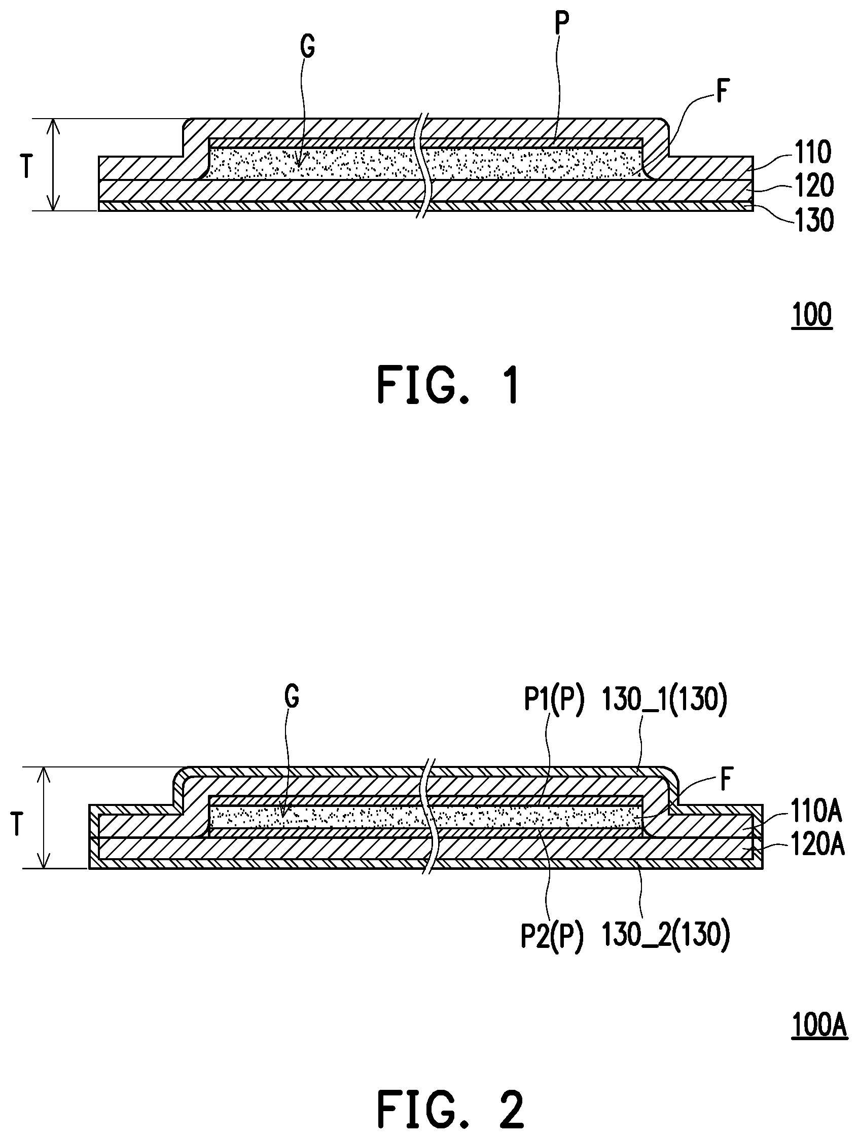
[0010] FIG. 1 is a schematic cross-sectional diagram illustrating a heat transferring module according to an embodiment of the invention.
[0011] FIG. 2 is a schematic cross-sectional diagram illustrating a heat transferring module according to another embodiment of the invention.
[0012] FIG. 3A to FIG. 3E are respectively schematic cross-sectional diagrams illustrating a manufacturing process of the heat transferring module depicted in FIG. 2.
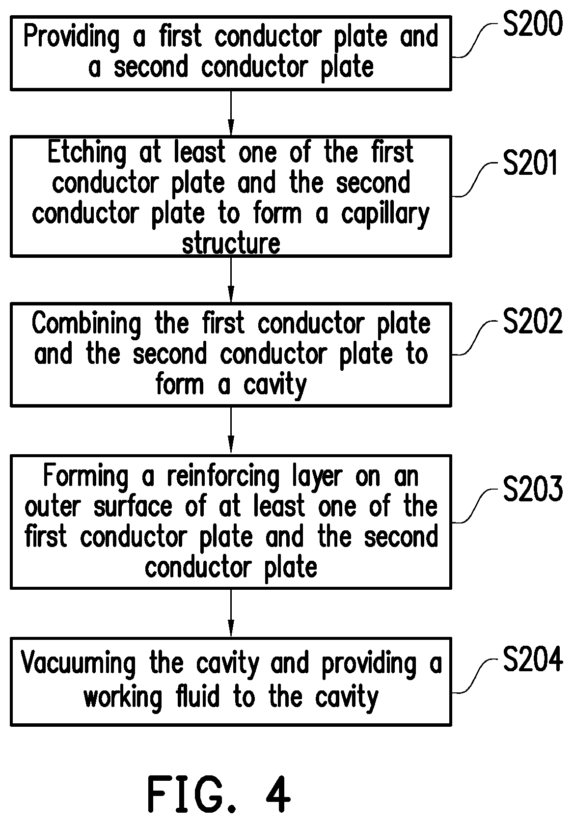
[0013] FIG. 4 is a flowchart illustrating steps of a manufacturing method of a heat transferring module according to an embodiment of the invention.
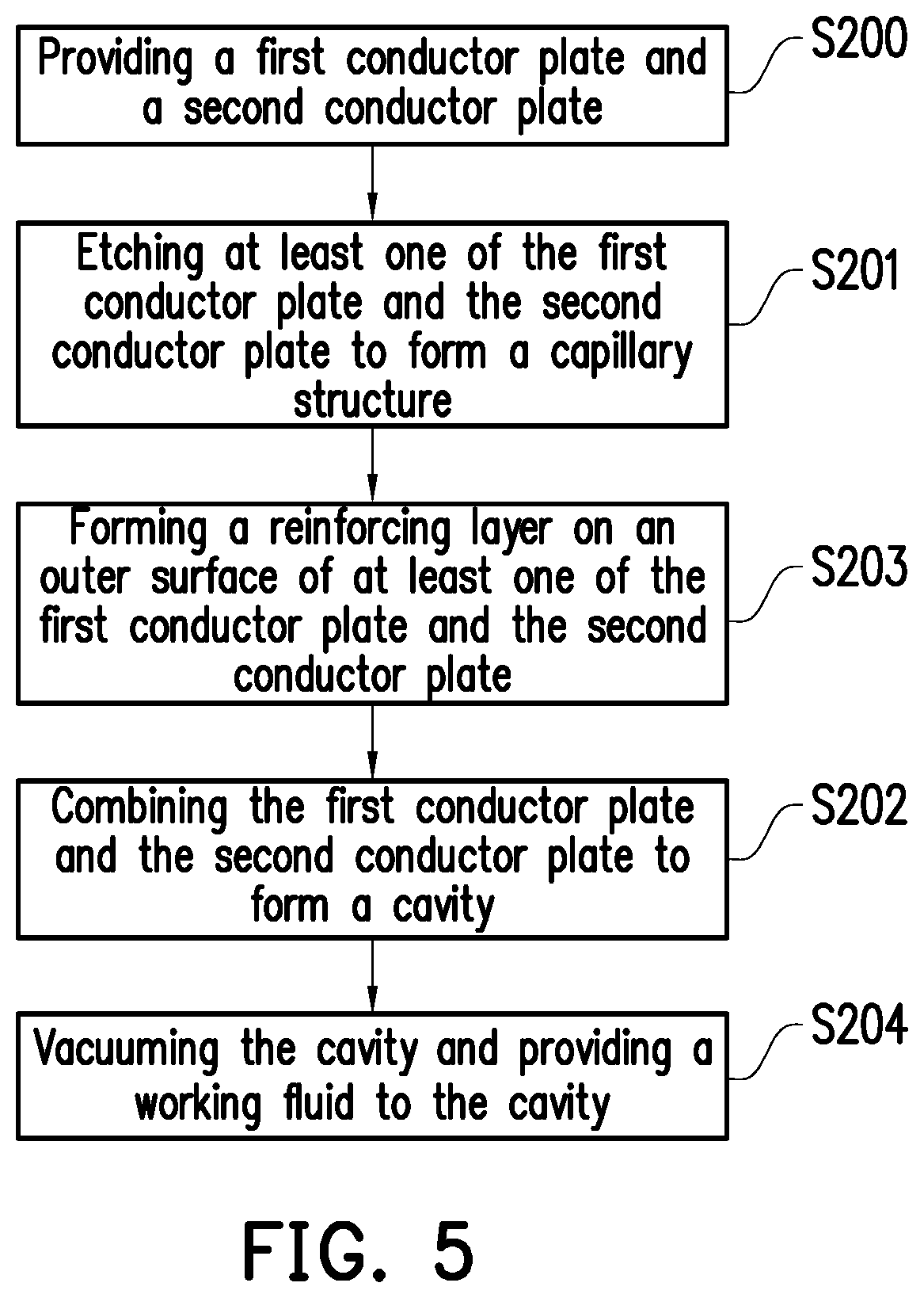
[0014] FIG. 5 is a flowchart illustrating steps of a manufacturing method of a heat transferring module according to another embodiment of the invention.
[0015] FIG. 6 is a flowchart illustrating steps of a manufacturing method of a heat transferring module according to another embodiment of the invention.
DESCRIPTION OF EMBODIMENTS
[0016] FIG. 1 is a schematic cross-sectional diagram illustrating a heat transferring module according to an embodiment of the invention. Referring to FIG. 1, the present embodiment provides a heat transferring module 100 adapted to contact a heating element and transfer heat generated by the heating element to a heat dissipation element, such as a fan or heat dissipation fins, or to outside by means of heat conduction, so as to achieve a heat dissipation effect. For instance, the heat transferring module 100 is a thin vapor chamber with a maximum thickness T, for example, less than or equal to 0.5 mm. The heating element is, for example, a central processing unit, a processor chip or other heat generating electronic elements of a portable electronic device (e.g., a smart cell phone). The heat transferring module 100 transfers the heat by means of heat convection and transfers the heat by means of heat conduction. Thus, the heat generated by the heating element may be transferred to a heat dissipation element such as a fan or heat dissipation fins or to outside by means of heat convection and heat conduction, so as to achieve a heat dissipation effect. For descriptive convenience, a size of the heat transferring module 100 is merely schematically illustrated in FIG. 1 and does not represent an actual size ratio of the heat transferring module 100.
[0017] In the present embodiment, the heat transferring module 100 includes a first conductor plate 110, a second conductor plate 120, a working fluid F and a reinforcing layer 130. The first conductor plate 110 and the second conductor plate 120 are connected to each other to form a cavity G, and the working fluid F is located in the cavity. A thickness of the first conductor plate 110 ranges between 0.1 mm and 0.4 mm, and a thickness of the second conductor plate ranges between 0.1 mm and 0.4 mm. In the present embodiment, the thickness of the first conductor plate 110 is 0.4 mm, and the thickness of the first conductor plate 110 is 0.1 mm. In the present embodiment, a material of the first conductor plate 110 and the second conductor plate 120 includes a copper alloy. However, in other embodiments, a material of at least one of the first conductor plate 110 and the second conductor plate 120 is selected from a group consisting of copper, aluminum and titanium, but the application is not limited thereto. A shape of at least one of the first conductor plate 110 and the second conductor plate 120 may be formed by stamping design, so as to form the cavity G after the first conductor plate 110 and the second conductor plate 120 are combined. In the present embodiment, a method of connecting the first conductor plate 110 and the second conductor plate 120 to each other is, for example, welding, but the application is not limited thereto.
[0018] To be detailed, at least one of the first conductor plate 110 and the second conductor plate 120 has a capillary structure P, and this capillary structure P is located on an inner surface of at least one of the first conductor plate 110 and the second conductor plate 120. For example, in the present embodiment, the thickness of the first conductor plate 110 is greater than the thickness of the second conductor plate 120, and thus, the first conductor plate 110 may be designed with the capillary structure P, as illustrated in FIG. 1. In the present embodiment, the capillary structure P is formed by, for example, etching a plate body of a conductor plate to form a micro structure capable of generating a capillarity phenomenon. The working fluid F may be condensed from a gas into a liquid by the capillary structure P, so as to achieve a purpose of heat transfer.
[0019] Specifically, during the process of heat dissipation, the heat of the heating element is transferred to the heat transferring module 100, and the working fluid F which is more adjacent to the heating element is heated and evaporated into a gas which flows upward and fills up the entire cavity G. When the evaporated working fluid F flows to a location which is relatively far away from the heating element, as this location has a relatively low temperature, the working fluid F, after exchanging heat with another medium (e.g., the capillary structure P, the first conductor plate 110, the second conductor plate 120 or cool air) and being condensed into a liquid, flows back by the capillarity phenomenon of the first conductor plate 110 and the second conductor plate 120. The evaporation and condensation operations are repeatedly performed inside the cavity G. Thus, the heat transferring module 100 may dissipate the heat generated by the heating element to other media.
[0020] The reinforcing layer 130 is formed on an outer surface of at least one of the first conductor plate 110 and the second conductor plate 120, and a structural strength of the reinforcing layer 130 is greater than a structural strength of the first conductor plate 110 and a structural strength of the second conductor plate 120. Thus, the structural strength of at least one of the first conductor plate 110 and the second conductor plate 120 may be improved, such that the thickness of at least one of the first conductor plate 110 and the second conductor plate 120 may be reduced for being used in manufacturing a thin vapor chamber.
[0021] To be detailed, a material of the reinforcing layer 130 includes a tungsten-nickel alloy or a nickel-cobalt alloy, and, in the present embodiment, the reinforcing layer 130 is formed on the outer surface of the second conductor plate 120 by means of electroplating. In other words, the reinforcing layer 130 is an electroplated reinforcing layer. In this way, the structural strength of the second conductor plate 120 may be further improved. It is to be mentioned that in the heat transferring module 100, two conductor plates which respectively include a thick one and a thin one may be selected to serve as the first conductor plate 110 and the second conductor plate 120, the thicker conductor plate is etched to form the capillary structure P, and the thinner conductor plate is electroplated to form the reinforcing layer 130. The relative thickness and the manufacturing process of each of the first conductor plate 110 and the second conductor plate 120 are not limited in the application. In this way, when the first conductor plate 110 and the second conductor plate 120 are combined together, a preferable heat transfer effect may be brought by the capillary structure P, and a preferable structural stability may be brought by the reinforcing layer 130.
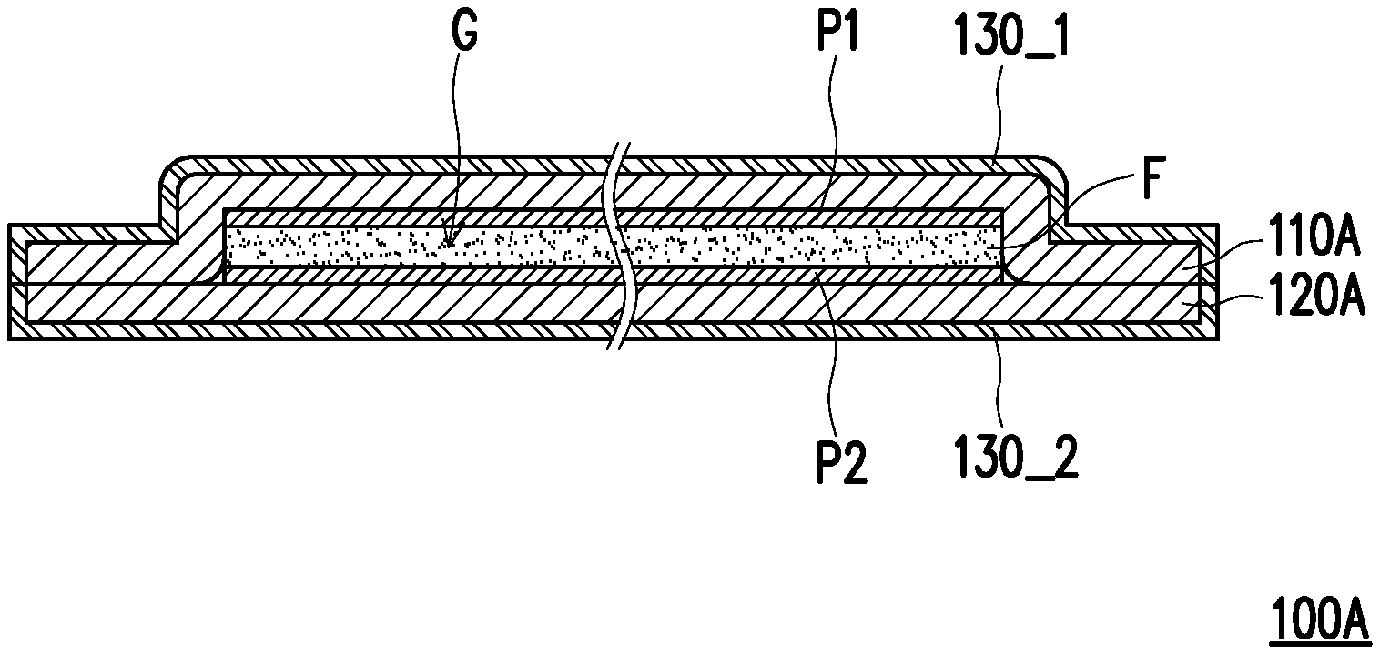
[0022] FIG. 2 is a schematic cross-sectional diagram illustrating a heat transferring module according to another embodiment of the invention. Referring to FIG. 2, a heat transferring module 100A of the present embodiment is similar to the heat transferring module 100 illustrated in FIG. 1. The difference therebetween is as follows. In the present embodiment, a second conductor plate 120A also has the capillary structure P, and the reinforcing layer 130 is formed on the outer surface of each of a first conductor plate 110A and the second conductor plate 120A. For descriptive convenience, a size of the heat transferring module 100A is merely schematically illustrated in FIG. 2 and does not represent an actual size ratio of the heat transferring module 100A.
[0023] To be detailed, in the present embodiment, each of the first conductor plate 110A and the second conductor plate 120A has a thickness of 0.25 mm, and the first conductor plate 110A and the second conductor plate 120A are respectively etched to form a first capillary structure P1 and a second capillary structure P2. In other words, the first capillary structure P1 is formed by a part of the first conductor plate 110A, and the second capillary structure P2 is formed by a part of the second conductor plate 120A. The reinforcing layer 130 includes a first reinforcing layer 130_1 and a second reinforcing layer 130_2. The first reinforcing layer 130_1 is formed on an outer surface of the first conductor plate 100A, and the second reinforcing layer 130_2 is formed on an outer surface of the second conductor plate 120A. Thus, when the first conductor plate 110A and the second conductor plate 120A are combined, a preferable heat transfer effect may be brought by the first capillary structure P1 and the second capillary structure P2, and a preferable structural stability may be brought by the first capillary structure P1 and the second capillary structure P2.
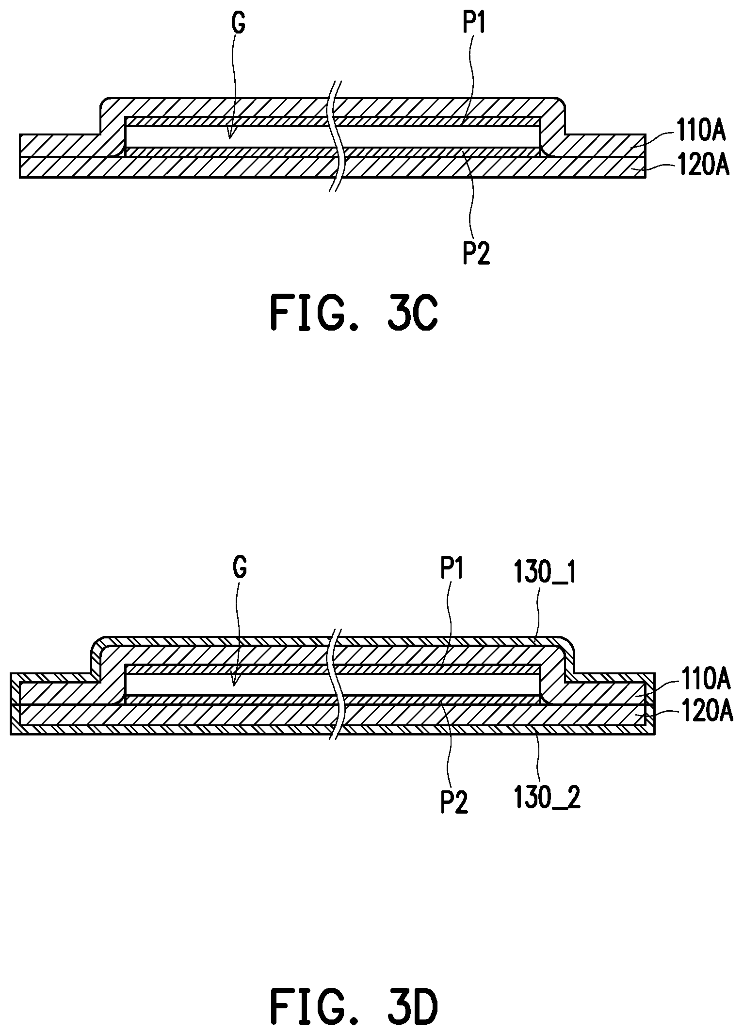
[0024] FIG. 3A to FIG. 3E are respectively schematic cross-sectional diagrams illustrating a manufacturing process of the heat transferring module depicted in FIG. 2. FIG. 4 is a flowchart illustrating steps of a manufacturing method of a heat transferring module according to an embodiment of the invention. Referring first to FIG. 2, FIG. 3A and FIG. 4 simultaneously, the application provides a manufacturing method of a heat transferring module, and the manufacturing method may be at least applied to the heat transferring module 100A illustrated in FIG. 2. However, the application is not limited thereto. In the present embodiment, first, step S200 is performed, the first conductor plate 110A and the second conductor plate 120A are provided, wherein shapes the first conductor plate 110A and the second conductor plate 120A may be formed by stamping design.
[0025] Referring to FIG. 2, FIG. 3B and FIG. 4 simultaneously, then, step S201 is performed. At least one of the first conductor plate 110A and the second conductor plate 120A is etched to form the capillary structure P. Specifically, in the present embodiment, the first conductor plate 110A is etched to form the first capillary structure P1, and the second conductor plate 120A is etched to form the second capillary structure P2.
[0026] Referring to FIG. 2, FIG. 3C and FIG. 4 simultaneously, then, step S202 is performed. The first conductor plate 110A and the second conductor plate 120A are combined to form the cavity G. Specifically, in the present embodiment, the first conductor plate 110A and the second conductor plate 120A are combined by means of welding, so as to form the cavity G inside the location that is welded.
[0027] Referring to FIG. 2, FIG. 3D and FIG. 4 simultaneously, then, step S203 is performed. The reinforcing layer 130 is formed on an outer surface of at least one of the first conductor plate 110A and the second conductor plate 120A, wherein the structural strength of the reinforcing layer 130 is greater than that of at least one of the first conductor plate 110A and the second conductor plate 120A. Specifically, in the present embodiment, the first reinforcing layer 130_1 is formed on the outer surface of the first conductor plate 110A by means of electroplating, and the second reinforcing layer 130_2 is formed on the outer surface of the second conductor plate 120A by means of electroplating.
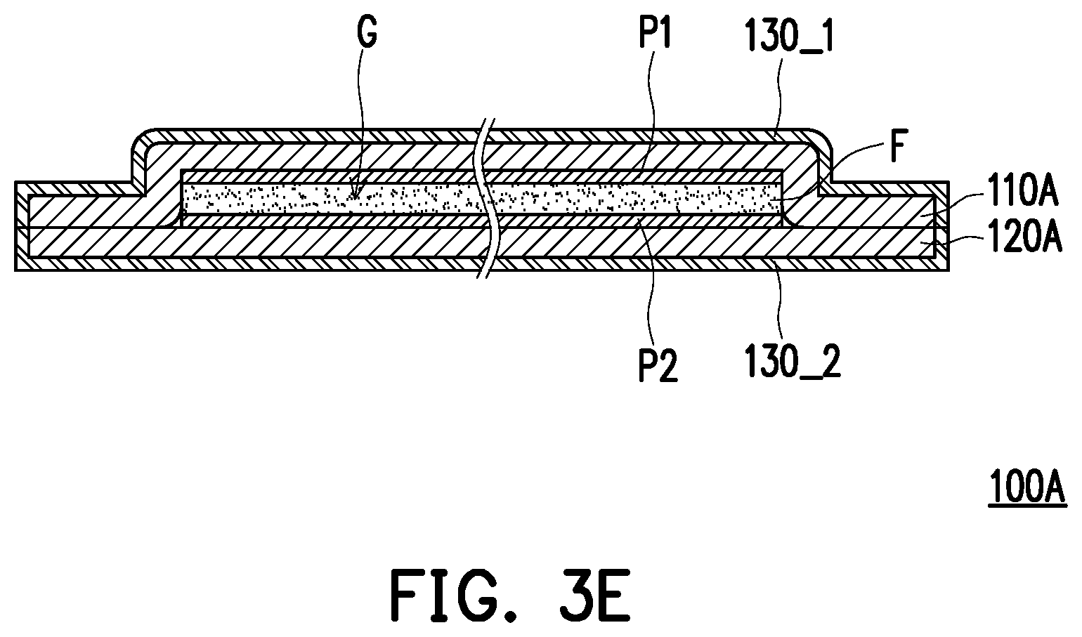
[0028] Referring to FIG. 2, FIG. 3E and FIG. 4 simultaneously, then, step S204 is performed. The cavity G is vacuumed, and the working fluid F is provided to the cavity G. Specifically, in the present embodiment, the vacuuming may be performed via a reserved through hole (not shown) on the first conductor plate 110A or the second conductor plate 120A, the working fluid F is provided into the cavity G after the vacuuming, and finally, the through hole is sealed by means of welding. Thereby, the heat transferring module 100A may be formed.
[0029] FIG. 5 is a flowchart illustrating steps of a manufacturing method of a heat transferring module according to another embodiment of the invention. Referring to FIG. 2 and FIG. 5, the manufacturing method of the heat transferring module may be at least applied to the heat transferring module 100A illustrated in FIG. 2. However, the application is not limited thereto. A manufacturing method of the heat transferring module 100A of the present embodiment is similar to the manufacturing method of the heat transferring module illustrated in FIG. 4. The difference therebetween is as follows. In the present embodiment, step S203 is performed after step S201 of etching to form the capillary structure P is performed. The reinforcing layer 130 is formed on the outer surface of at least one of the first conductor plate 110A and the second conductor plate 120A, wherein the structural strength of the reinforcing layer 130 is greater than that of at least one of the first conductor plate 110A and the second conductor plate 120A. Then, after the aforementioned steps are completed, step S202 is performed, wherein the first conductor plate 110A and the second conductor plate 120A are combined to form the cavity G. In other words, among the aforementioned steps, the steps of etching to form the capillary structure P, forming the reinforcing layer 130 and combining the first conductor plate 110A and the second conductor plate 120A are performed in sequence. Thus, the embodiments may have different manufacturing processes to be adapted to structural requirements.
[0030] FIG. 6 is a flowchart illustrating steps of a manufacturing method of a heat transferring module according to another embodiment of the invention. Referring to FIG. 2 and FIG. 6, the manufacturing method of the heat transferring module may be at least applied to the heat transferring module 100A illustrated in FIG. 2. However, the application is not limited thereto. A manufacturing method of the heat transferring module 100A of the present embodiment is similar to the manufacturing method of the heat transferring module illustrated in FIG. 4. The difference therebetween is as follows. In the present embodiment, step S203 is performed after step S200 of providing the first conductor plate 110A and the second conductor plate 120A is performed, wherein the reinforcing layer 130 is formed on the outer surface of at least one of the first conductor plate 110A and the second conductor plate 120A, wherein the structural strength of the reinforcing layer 130 is greater than that of at least one of the first conductor plate 110A and the second conductor plate 120A. Then, after the aforementioned steps are completed, step S201 is performed, where at least one of the first conductor plate 110A and the second conductor plate 120A is etched to form the capillary structure P. Then, after the aforementioned steps are completed, step S202 is performed, where the first conductor plate 110A and the second conductor plate 120A are combined to form the cavity G. In other words, among the aforementioned steps, the steps of forming the reinforcing layer 130, etching to form the capillary structure P and combining the first conductor plate 110A and the second conductor plate 120A are performed in sequence. Thus, the embodiments may have different manufacturing processes to be adapted to structural requirements.
[0031] In view of the foregoing, in the heat transferring module and the manufacturing method thereof provided by the application, the reinforcing layer having the structural strength greater than that of each of the first conductor plate and the second conductor plate is formed on the outer surface of at least one of the first conductor plate and the second conductor plate. Thus, when the first conductor plate and the second conductor plate are combined together, a preferable heat transfer effect can brought by the capillary structure, and a preferable structural stability can be brought by the reinforcing layer.
[0032] Although the invention has been described with reference to the above embodiments, the invention is not limited to the above embodiments. It is apparent to one of ordinary skill in the art that modifications and variations to the described embodiments may be made without departing from the spirit and scope of the invention. Accordingly, the scope of the invention will be defined by the attached claims. What is claimed is:
* * * * *
D00000
D00001
D00002
D00003
D00004
D00005
D00006
D00007
XML
uspto.report is an independent third-party trademark research tool that is not affiliated, endorsed, or sponsored by the United States Patent and Trademark Office (USPTO) or any other governmental organization. The information provided by uspto.report is based on publicly available data at the time of writing and is intended for informational purposes only.
While we strive to provide accurate and up-to-date information, we do not guarantee the accuracy, completeness, reliability, or suitability of the information displayed on this site. The use of this site is at your own risk. Any reliance you place on such information is therefore strictly at your own risk.
All official trademark data, including owner information, should be verified by visiting the official USPTO website at www.uspto.gov. This site is not intended to replace professional legal advice and should not be used as a substitute for consulting with a legal professional who is knowledgeable about trademark law.