Cooling Device
NAKAE; Nobuya ; et al.
U.S. patent application number 16/595497 was filed with the patent office on 2020-04-16 for cooling device. This patent application is currently assigned to NIDEC CORPORATION. The applicant listed for this patent is NIDEC CORPORATION. Invention is credited to Takahiro IMANISHI, Akihiko MAKITA, Nobuya NAKAE, Takehito TAMAOKA, Toshihiko TOKESHI.
| Application Number | 20200116430 16/595497 |
| Document ID | / |
| Family ID | 70161568 |
| Filed Date | 2020-04-16 |

| United States Patent Application | 20200116430 |
| Kind Code | A1 |
| NAKAE; Nobuya ; et al. | April 16, 2020 |
COOLING DEVICE
Abstract
Provided is a cooling device which includes a plurality of cooling units and a blocking member and in which at least a portion of the blocking member is disposed between the cooling units.
| Inventors: | NAKAE; Nobuya; (Kyoto, JP) ; TOKESHI; Toshihiko; (Kyoto, JP) ; IMANISHI; Takahiro; (Kyoto, JP) ; MAKITA; Akihiko; (Kyoto, JP) ; TAMAOKA; Takehito; (Kyoto, JP) | ||||||||||
| Applicant: |
|
||||||||||
|---|---|---|---|---|---|---|---|---|---|---|---|
| Assignee: | NIDEC CORPORATION Kyoto JP |
||||||||||
| Family ID: | 70161568 | ||||||||||
| Appl. No.: | 16/595497 | ||||||||||
| Filed: | October 8, 2019 |
| Current U.S. Class: | 1/1 |
| Current CPC Class: | F28D 1/0246 20130101; F28F 2215/02 20130101; F28F 2255/02 20130101; F28D 1/0408 20130101; F28F 3/12 20130101; F28F 2270/00 20130101; F28D 2021/0029 20130101; F28F 1/325 20130101 |
| International Class: | F28D 1/02 20060101 F28D001/02; F28F 3/12 20060101 F28F003/12 |
Foreign Application Data
| Date | Code | Application Number |
|---|---|---|
| Oct 13, 2018 | JP | 2018-193912 |
Claims
1. A cooling device, comprising: a plurality of cooling units; and a blocking member, wherein at least a portion of the blocking member is arranged between the cooling units.
2. The cooling device according to claim 1, wherein the cooling units each include: a cold plate, extending in a horizontal direction; and a radiator disposed on an upper side of the cold plate in a first direction perpendicular to the horizontal direction, wherein the radiator includes a plurality of fins extending in the first direction and disposed in parallel in a second direction perpendicular to the first direction, and the blocking member is disposed between the cooling units horizontally in a third direction that is perpendicular to the second direction.
3. The cooling device according to claim 2, further comprising a cover member, wherein the cover member is disposed on an upper side of the radiator in the first direction.
4. The cooling device according to claim 3, wherein the cover member is disposed to straddle a plurality of the radiators.
5. The cooling device according to claim 1, wherein the blocking member has elasticity.
6. The cooling device according to claim 1, further comprising a pump.
Description
CROSS REFERENCE TO RELATED APPLICATIONS
[0001] This application claims the priority benefit of Japanese Patent Application No. 2018-193912, filed on Oct. 13, 2018. The entirety of the above-mentioned patent application is hereby incorporated by reference herein and made a part of this specification.
BACKGROUND
Technical Field
[0002] The present disclosure relates to a cooling device.
Description of Related Art
[0003] A conventional cooling device includes a plurality of radiators and a cooling fan which supplies cooling air to these radiators (for example, Patent Document 1: Japanese Patent Application Laid Open No. 2010-156467).
[0004] However, in the cooling device disclosed in Patent Document 1, since gaps are formed between a plurality of radiators, some of the cooling air of a cooling fan may flow between the plurality of radiators. Therefore, there is a possibility that the cooling air may not be blown to the radiators efficiently.
SUMMARY
[0005] The disclosure tries to address the cooling efficiency of a radiator by causing cooling air to be efficiently blown to the radiator.
[0006] According to one embodiment, the disclosure provides a cooling device, including a plurality of cooling units and a blocking member, in which at least a portion of the blocking member is arranged between the plurality of cooling units.
[0007] According to the above exemplary cooling device, the cooling efficiency of the radiator is improved.
BRIEF DESCRIPTION OF THE DRAWINGS
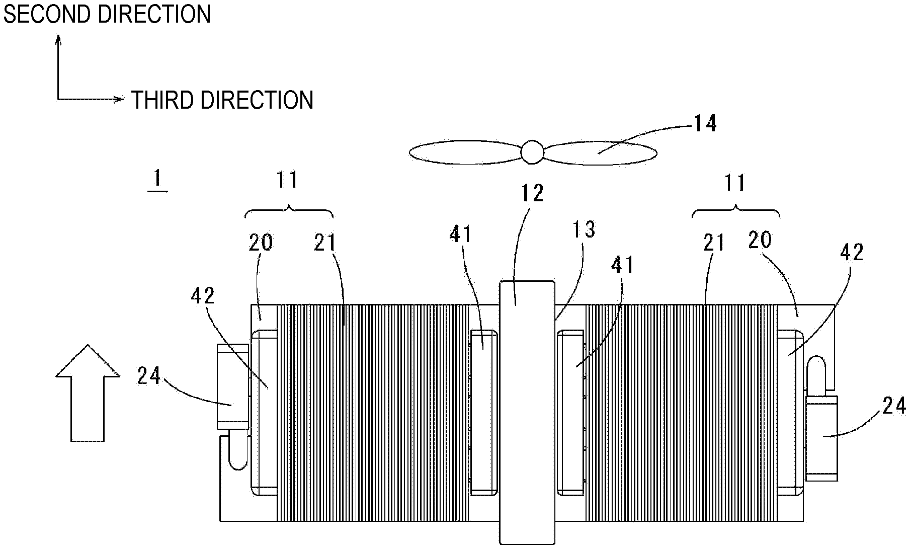
[0008] FIG. 1 is a plan view of a cooling device according to an exemplary first embodiment of the present disclosure.
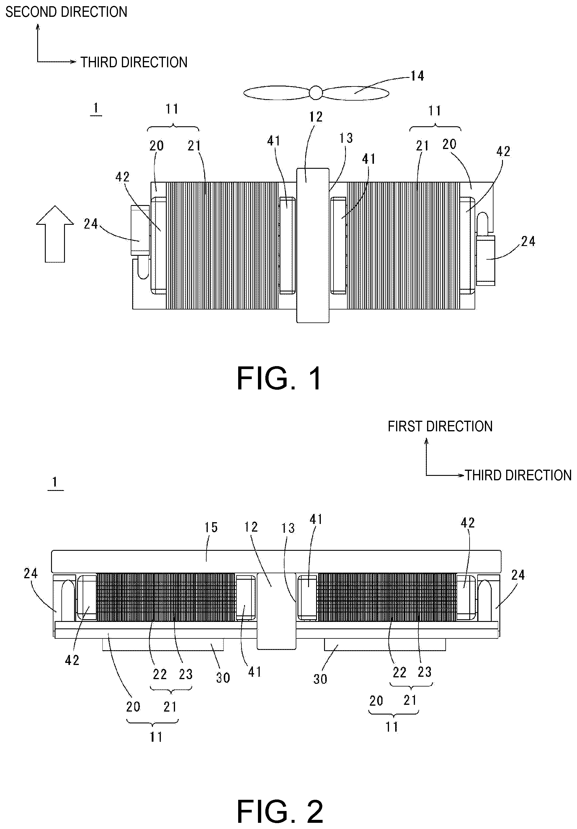
[0009] FIG. 2 is a front view of the cooling device according to the exemplary first embodiment of the present disclosure.
[0010] FIG. 3 is a perspective view of a cooling unit according to the exemplary first embodiment of the present disclosure.
[0011] FIG. 4 is a plan view of a cooling device according to an exemplary second embodiment of the present disclosure.
DESCRIPTION OF EMBODIMENTS
[0012] Hereinafter, exemplary embodiments of the present disclosure will be described with reference to the drawings. In the present disclosure, a vertical direction is defined such that a direction in which a radiator 21 is disposed with respect to a cold plate 20 is referred to as an "upper side," and a direction opposite to that in which the radiator 21 is disposed is referred to as a "lower side." In the present disclosure, a direction in which the radiator 21 is disposed with respect to the cold plate 20 is referred to as a "first direction." A direction which is perpendicular to the "first direction" and in which a fin 22 extends in a longitudinal direction is referred to as a "second direction." A direction perpendicular to the "second direction" in a horizontal direction is referred to as a "third direction," based on which shapes and positional relationships between respective parts will be described. Also, a direction in which cooling air flows from an upstream side to a downstream side is indicated by an arrow in the figure. However, this is a definition of the vertical direction and horizontal direction merely for convenience of description and does not limit an orientation of a cooling device 1 according to the present disclosure at the time of manufacturing and use.
[0013] Also, in the present disclosure, a "parallel direction" includes a substantially parallel direction. Further, in the present disclosure, a "perpendicular direction" includes a substantially perpendicular direction.
[0014] <First Embodiment>
[0015] A cooling device according to an exemplary first embodiment of the present disclosure will be described. FIG. 1 is a plan view of a cooling device according to the exemplary first embodiment of the present disclosure. FIG. 2 is a front view of the cooling device according to the exemplary first embodiment of the present disclosure. FIG. 3 is a perspective view of a cooling unit according to the exemplary first embodiment of the present disclosure.
[0016] The cooling device 1 includes a plurality of cooling units 11, a blocking member 12, and a cover member 15.
[0017] At least a portion of the blocking member 12 is disposed between adjacent cooling units 11. When a plurality of cooling units 11 are disposed, since cooling air flows into a space between the cooling units 11, a cooling efficiency of the radiator 21 decreases. When the blocking member 12 is disposed between adjacent cooling units 11, cooling air flowing between the adjacent cooling units 11 is hindered, the cooling air is caused to flow toward the radiator 21 side, and thereby the cooling efficiency of the radiator 21 is improved.
[0018] Each of the cooling units 11 includes the cold plate 20 and the radiator 21. The radiator 21 is disposed on an upper side of the cold plate 20. An upper surface of the cold plate 20 and a lower surface of the radiator 21 are in contact with each other.
[0019] <Cold Plate>
[0020] The cold plate 20 is made of a metal having high thermal conductivity such as copper or aluminum and has a rectangular plate shape that extends in the horizontal direction when viewed from above. Further, the cold plate 20 of the present embodiment has a quadrangular shape when viewed from above but is not limited thereto, and may have, for example, a polygonal shape having a plurality of corners or a circular shape when viewed from above. A heat generating component 30 is disposed on a lower surface of the cold plate 20.
[0021] The cold plate 20 includes a first refrigerant flow path (not illustrated) through which a refrigerant flows. The first refrigerant flow path is a space in the cold plate 20. A plurality of blades (not illustrated) disposed side by side parallel to each other are provided inside the first refrigerant flow path. Also, an inlet (not illustrated) and an outlet (not illustrated) are provided in the first refrigerant flow path. The refrigerant that has flowed into the first refrigerant flow path via the inlet is discharged from the first refrigerant flow path via the outlet.
[0022] The refrigerant in the present embodiment is a liquid, and for example, an antifreeze such as an ethylene glycol aqueous solution or a propylene glycol aqueous solution, pure water, or the like is used.
[0023] <Radiator>
[0024] The radiator 21 is disposed on the upper side of the cold plate 20 in the first direction perpendicular to the horizontal direction. The radiator 21 includes a plurality of fins 22 for cooling and a pipe 23. The fins 22 are formed in a flat plate, stand upward from the upper surface of the cold plate 20, and extend in the second direction perpendicular to the first direction. The plurality of fins 22 extend parallel to each other on the upper surface of the cold plate 20 and are disposed at equal intervals. The fins 22 provided on the radiator 21 are disposed parallel to each other. Further, in a plurality of cooling devices 1, the respective fins 22 extend in the same second direction.
[0025] A lower end of each of the fins 22 is in contact with the upper surface of the cold plate 20. Thereby, thermal conductivity from the cold plate 20 to the fin 22 is improved. Further, the fin 22 and the cold plate 20 may be separate members or the same member. In the present embodiment, the fin 22 is a separate member from the cold plate 20. For example, the lower end of the fin is joined to the upper surface of the cold plate 20 by welding.
[0026] When the fin 22 is the same member as the cold plate 20, the fin 22 is formed, for example, by a process of cutting the cold plate 20. Further, when the fin 22 and the cold plate 20 are separate members, the fin 22 may be a metal having high thermal conductivity such as copper or aluminum as in the cold plate 20 described above. When the fin 22 is formed of a metal having high thermal conductivity as in the cold plate 20, heat from the cold plate 20 can be efficiently transmitted to the fin 22.
[0027] The pipe 23 has a hollow inside and forms a second refrigerant flow path through which the refrigerant passes. One end portion of the second refrigerant flow path communicates with the first refrigerant flow path. As will be described below, the second refrigerant flow path may communicate with the first refrigerant flow path via, for example, a tank or a pump.
[0028] The pipe 23 extends linearly in the third direction. The pipe 23 is inserted into through holes provided in the plurality of fins 22 and fixed to the plurality of fins 22 by welding. At this time, a direction in which the pipe 23 extends and a direction in which the fins 22 extend are perpendicular to each other. That is, the plurality of fins 22 extend in the second direction, and the pipe 23 extends in the third direction in the present embodiment.
[0029] In the present embodiment, the cooling units 11 have the same configuration and the same size. The cooling units 11 are disposed parallel to the third direction. The cooling units 11 have end portions in the second direction which are coplanar with each other. Among the plurality of cooling units 11, adjacent cooling units 11 are disposed in the third direction with a gap therebetween. Also, the cooling units 11 may have sizes different from each other.
[0030] <Tank>
[0031] Each of the cooling units 11 further includes a first tank 41 and a second tank 42. One end of the pipe 23 is connected to the first tank 41, and the other end of the pipe 23 is connected to the second tank 42. The first tank 41 and the second tank 42 are disposed to face each other in the direction in which the pipe 23 extends. The refrigerant smoothly flows linearly from the first tank 41 to the second tank 42 through the pipe 23.
[0032] The first tank 41 and the second tank 42 are disposed parallel to a direction in which the fins 22 are arranged, and thereby more of the plurality of fins 22 can be disposed between the first tank 41 and the second tank 42 at predetermined intervals. Thereby, a surface area of the entire fins 22 can be enlarged so that a cooling performance of the radiator 21 can be improved. Also, the pipe 23 can be easily connected to the first tank 41 and the second tank 42.
[0033] The pipe 23 penetrates side surfaces of the first tank 41 and the second tank 42 to be directly connected to the first tank 41 and the second tank 42. Thereby, the number of parts of the cooling device 1 can be reduced.
[0034] The first tank 41 and the second tank 42 are cuboids. A hole (not illustrated) connected to a pump 24 to be described below is provided in the second tank.
[0035] When the first tank 41 and the second tank 42 are provided, an amount of the refrigerant circulated in the cooling unit 11 can be increased. Accordingly, a cooling efficiency of the cooling unit 11 is improved.
[0036] <Pump>
[0037] The cooling unit 11 further includes the pump 24. In the present embodiment, the pump 24 is a centrifugal-type pump and includes a pump flow path (not illustrated) that is a flow path of the refrigerant inside a rectangular parallelepiped housing. An impeller (not illustrated) is disposed in the pump flow path. The housing includes a suction port (not illustrated) and a discharge port (not illustrated).
[0038] The suction port of the pump 24, the radiator 21, and the second flow path are connected directly or indirectly. The discharge port communicates with the suction port. In the present embodiment, the suction port of the pump 24 and the radiator 21 are connected via the second tank 42.
[0039] The impeller of the pump 24 is supported to be rotatable around a central axis extending in the first direction and is connected to a rotating shaft of a motor (not illustrated). The impeller rotates due to driving of the motor, and the refrigerant that has flowed in from the suction port is discharged from the discharge port. The pump 24 suctions the refrigerant in the direction in which the pipe 23 extends through the suction port.
[0040] In the present embodiment, the pump 24 is disposed adjacent to the radiator 21.
[0041] In the cold plate 20, a notch part 20a in which a side surface is cut out is formed. At least a portion of the pump 24 is disposed in the notch part 20a and is disposed to face the radiator 21 in the second direction. Specifically, the pump is disposed on a side surface of the radiator 21. Thereby, the entire cooling unit 11 can be further reduced in size. Also, the pump 24 can be increased in size and have a high output in the limited space of the cooling device 1 while an increase in size of the entire cooling unit 11 is suppressed.
[0042] (Operation of Cooling Unit)
[0043] The pump 24 is driven by bringing the heat generating component 30 to be cooled such as, for example, a central processing unit (CPU) into contact with the lower surface of the cold plate 20. Thereby, the refrigerant circulates in the order of the first refrigerant flow path, the first tank 41, the second refrigerant flow path, and the second tank 42. Heat generated by the heat generating component 30 is transmitted to the cold plate 20. The heat transmitted to the cold plate 20 is transmitted to the fins 22 via the refrigerant flowing through the first refrigerant flow path and the second refrigerant flow path. Thereby, heat dissipation is performed via the fins 22 and a temperature rise in the heat generating component 30 can be inhibited.
[0044] <First Embodiment>
[0045] A slit 13 is formed between adjacent cooling units 11 of the plurality of cooling units 11. The slit 13 is a gap between adjacent cooling units 11. In the present embodiment, the slit 13 indicates a gap between adjacent cooling units 11 in the third direction. Thereby, when the cooling units 11 are arranged, since interference between the cooling units 11 can be inhibited, the cooling device 1 can be prevented from being damaged. On the other hand, when a gap is provided between adjacent cooling units 11, there is a likelihood that cooling air will flow into the gap and the cooling performance of the radiator 21 will be reduced.
[0046] <Blocking Member>
[0047] At least a portion of the blocking member 12 is disposed in the slit 13. When the blocking member 12 is disposed in the slit 13, cooling air does not easily flow through the slit 13. Therefore, the cooling air generated by a cooling fan 14 to be described below is supplied to the radiator 21, and heat dissipation from the heat generating component 30 can be efficiently performed using the radiator 21.
[0048] The blocking member 12 may be in contact with end surfaces on the third direction side of adjacent cooling units 11. When a gap between the blocking member 12 and the end surfaces in the third direction of the cooling units 11 is eliminated, the cooling air flowing into the slit 13 is further inhibited. Therefore, heat dissipation from the heat generating component 30 can be efficiently performed using the radiator 21 of the cooling unit 11.
[0049] The blocking member 12 need only be provided at an end portion in the second direction of the slit 13. Specifically, when the blocking member 12 is disposed at an entrance through which cooling air enters the slit 13, the cooling air flowing into the slit 13 can be inhibited. Compared to a case in which the blocking member 12 is disposed in the entire region in the slit 13, an amount of the blocking member 12 used can be reduced.
[0050] In the present embodiment, the blocking member 12 is inserted into the slit 13 from the upper side in the first direction. Further, the blocking member 12 may also be inserted into the slit 13 from the second direction.
[0051] The blocking member 12 may have elasticity such as, for example, that of a sponge or a rubber. Insertion property when the blocking member 12 is inserted into the slit 13 can then be improved. Specifically, since the blocking member 12 is deformed along a shape of the slit 13, the blocking member 12 can be easily arranged even when a portion of the slit 13 has a complicated shape. Also, the blocking member 12 may have a plate shape using such as, for example, a plastic which does not have elasticity.
[0052] At least a portion of the cover member 15 is disposed on an upper side of the radiator 21 in the first direction. Specifically, the cover member 15 is disposed on an upper surface of the fins 22 on the upper side in the first direction. When cooling air flows into a space on the upper side of the radiator 21 in the first direction, the cooling efficiency of the radiator 21 decreases. When the cover member 15 is disposed in the space on the upper side of the radiator 21 in the first direction, the cooling air flowing into the space is hindered. Therefore, heat dissipation from the heat generating component 30 can be efficiently performed using the radiator 21 of the cooling unit 11.
[0053] The cover member 15 is disposed to straddle a plurality of radiators 21. Specifically, the cover member 15 is disposed to be continuous over upper surfaces of adjacent radiators 21. In this case, the upper surface in the first direction of the blocking member 12 faces a surface on a lower side in the first direction of the cover member 15. Thereby, the number of parts can be reduced compared to a case in which the cover member 15 is disposed on an upper side of each radiator 21. Also, the number of work man-hours for attaching the cover member 15 can be reduced.
[0054] The upper surface in the first direction of the blocking member 12 and the surface on the lower side in the first direction of the cover member 15 may be in contact with each other. In this case, the slit 13 can be more reliably closed. Also, a portion of the cover member 15 may be disposed in the slit 13.
[0055] <Fan>
[0056] The fan 14 is provided to face the cooling unit 11 in the second direction. The fan 14 of the present embodiment is an axial flow type fan. When cooling air blows in a direction in which the fins 22 extend in a longitudinal direction (second direction), heat dissipation from the fins 22 is promoted, and the cooling performance of the radiator 21 is improved. Also, a plurality of fans 14 may be disposed to face the cooling units 11 in the second direction.
[0057] <Second Embodiment>
[0058] Next, a second embodiment will be described. FIG. 4 is a plan view illustrating a cooling device 1 of the second embodiment. For convenience of description, portions the same as those in the above-described first embodiment are denoted by the same reference signs.
[0059] At least one of a plurality of cooling units 11 is disposed downstream in cooling air in a second direction with respect to the other cooling units 11. Specifically, the other cooling units 11B are disposed downstream in the cooling air with respect to one cooling unit 11A. Specifically, when viewed from the second direction, all the cooling units 11A and 11B do not overlap in the second direction. More specifically, the radiators 21A and 21B of the cooling units 11A and 11B do not overlap in the second direction. Cooling air flowing from the second direction flows into the radiator 21B of the cooling unit 11B on the downstream side without being hindered by the radiators 21A of the cooling units 11A on the upstream side. Therefore, even when a plurality of radiators 21A and 21B are disposed in the second direction, cooling air can efficiently flow into all the cooling units 11A and 11B.
[0060] Fins 22A and 22B of the radiators 21A and 21B of the respective cooling units 11A and 11B extend in the second direction. In other words, directions in which the fins 22A and 22B of the cooling units 11A and 11B extend are the same.
[0061] A blocking member 12A may be provided between the cooling units 11A and the cooling unit 11B. Cooling air passing between adjacent cooling units 11A flows into spaces between the cooling units 11A and the cooling unit 11B, and thereby a cooling efficiency of the radiator 21B of the cooling unit 11B decreases. When the blocking member 12A is provided in the spaces between the cooling units 11A and the cooling unit 11B, the cooling air flowing into the spaces is hindered so that the cooling air is caused to flow into the radiator 21B, and thereby the cooling efficiency of the radiator 21B improves.
[0062] (Other)
[0063] The embodiments described above are merely examples of the present disclosure. Configurations of the embodiments may be changed as appropriate without departing from the technical spirit of the present disclosure. Also, the embodiments may be implemented in combination within a possible range.
[0064] In the above-described embodiment, a centrifugal-type pump 24 is used, but a diaphragm-type pump, a cascade-type pump, or the like may also be used. Also, although the axial flow type fan was used for the fan 14, for example, a centrifugal-type fan or the like may also be used.
[0065] It will be apparent to those skilled in the art that various modifications and variations can be made to the disclosed embodiments without departing from the scope or spirit of the disclosure. In view of the foregoing, it is intended that the disclosure covers modifications and variations provided that they fall within the scope of the following claims and their equivalents.
* * * * *
D00000
D00001
D00002
XML
uspto.report is an independent third-party trademark research tool that is not affiliated, endorsed, or sponsored by the United States Patent and Trademark Office (USPTO) or any other governmental organization. The information provided by uspto.report is based on publicly available data at the time of writing and is intended for informational purposes only.
While we strive to provide accurate and up-to-date information, we do not guarantee the accuracy, completeness, reliability, or suitability of the information displayed on this site. The use of this site is at your own risk. Any reliance you place on such information is therefore strictly at your own risk.
All official trademark data, including owner information, should be verified by visiting the official USPTO website at www.uspto.gov. This site is not intended to replace professional legal advice and should not be used as a substitute for consulting with a legal professional who is knowledgeable about trademark law.