Ammonia-based Flue Gas Desulfurization System And Method
Leicht; Paul M. ; et al.
U.S. patent application number 16/599864 was filed with the patent office on 2020-04-16 for ammonia-based flue gas desulfurization system and method. The applicant listed for this patent is Marsulex Environmental Technologies Corporation. Invention is credited to Michael T. Hammer, Paul M. Leicht, Michael L. Mengel.
| Application Number | 20200116355 16/599864 |
| Document ID | / |
| Family ID | 70161210 |
| Filed Date | 2020-04-16 |

| United States Patent Application | 20200116355 |
| Kind Code | A1 |
| Leicht; Paul M. ; et al. | April 16, 2020 |
AMMONIA-BASED FLUE GAS DESULFURIZATION SYSTEM AND METHOD
Abstract
Wet flue gas desulfurization systems and methods for contacting a flue gas with a scrubbing liquid to produce ammonium thiosulfate. The scrubbing liquid absorbs sulfur dioxide and optionally additional acidic gases from the flue gas to produce a scrubbed flue gas, the scrubbing liquid with the absorbed sulfur dioxide therein is collected, and ammonia and elemental sulfur are introduced into the collected scrubbing liquid to react the ammonia, the absorbed sulfur dioxide, and the elemental sulfur in the collected scrubbing liquid to produce ammonium thiosulfate.
| Inventors: | Leicht; Paul M.; (Myerstown, PA) ; Mengel; Michael L.; (Fredericksburg, PA) ; Hammer; Michael T.; (Birdsboro, TN) | ||||||||||
| Applicant: |
|
||||||||||
|---|---|---|---|---|---|---|---|---|---|---|---|
| Family ID: | 70161210 | ||||||||||
| Appl. No.: | 16/599864 | ||||||||||
| Filed: | October 11, 2019 |
Related U.S. Patent Documents
| Application Number | Filing Date | Patent Number | ||
|---|---|---|---|---|
| 62744338 | Oct 11, 2018 | |||
| Current U.S. Class: | 1/1 |
| Current CPC Class: | F23J 15/04 20130101; F23J 2215/20 20130101; F23J 2219/40 20130101; F23J 2217/50 20130101 |
| International Class: | F23J 15/04 20060101 F23J015/04 |
Claims
1. A wet flue gas desulfurization system comprising: an absorber through which a flue gas flows; a contact region in the absorber having means for contacting the flue gas with a scrubbing liquid so that the scrubbing liquid absorbs sulfur dioxide and optionally additional acidic gases from the flue gas to produce a scrubbed flue gas; a reaction tank located so that the scrubbing liquid is received in the reaction tank after the scrubbing liquid has absorbed the sulfur dioxide from the flue gas; a source of elemental sulfur; and a device for introducing the elemental sulfur from the source into the scrubbing liquid within the reaction tank; wherein the scrubbing liquid contains ammonia and ammonium thiosulfate is produced as a byproduct of a reaction of the ammonia, the sulfur dioxide, and the elemental sulfur in the scrubbing liquid.
2. The wet flue gas desulfurization system of claim 1, further comprising an injector that injects the ammonia into the scrubbing liquid.
3. The wet flue gas desulfurization system of claim 1, wherein the device for introducing the elemental sulfur is an injector.
4. The wet flue gas desulfurization system of claim, wherein the absorber is a converted absorber of a pre-existing calcium-based flue gas desulfurization system.
5. The wet flue gas desulfurization system of claim 1, wherein the absorber is a converted absorber of a pre-existing ammonia-based flue gas desulfurization system.
6. A wet flue gas desulfurization method comprising: contacting a flue gas with a scrubbing liquid so that the scrubbing liquid absorbs sulfur dioxide and optionally additional acidic gases from the flue gas to produce a scrubbed flue gas; collecting the scrubbing liquid with the absorbed sulfur dioxide and introducing ammonia and elemental sulfur into the collected scrubbing liquid to react the ammonia, the absorbed sulfur dioxide, and the elemental sulfur in the collected scrubbing liquid to produce ammonium thiosulfate.
7. The wet flue gas desulfurization method of claim 6, the method further comprising controlling operating parameters including temperature, pH, and sulfur concentration in the collected scrubbing liquid to form the ammonium thiosulfate without forming a secondary byproduct.
8. The wet flue gas desulfurization method of claim 7, wherein the method is performed with a wet flue gas desulfurization system.
9. The wet flue gas desulfurization method of claim 8, the method further comprising constructing the wet flue gas desulfurization system by converting a pre-existing calcium-based flue gas desulfurization system.
10. The wet flue gas desulfurization method of claim 8, the method further comprises constructing the wet flue gas desulfurization system by converting a pre-existing ammonia-based flue gas desulfurization system.
Description
CROSS-REFERENCE TO RELATED APPLICATIONS
[0001] This application claims the benefit of U.S. Provisional Application No. 62/744,338, filed Oct. 11, 2018, the contents of which are incorporated herein by reference.
BACKGROUND OF THE INVENTION
[0002] The present invention generally relates to flue gas desulfurization (FGD) systems and processes for removing acidic gases from gas streams, including but not limited to utility and industrial flue gases. The invention particularly relates to an ammonia-based flue gas desulfurization (FGD) system and method for producing ammonium thiosulfate as a valuable byproduct.
[0003] Gas-liquid contactors and absorbers (hereinafter collectively referred to as absorbers) are widely used to remove substances such as gases and particulate matter from flue gases produced by utility and industrial plants. Often of particular concern are sulfur dioxide (SO.sub.2) and other acidic gases produced by the combustion of fossil fuels and various industrial operations. These gases are known to be hazardous to the environment and their emission into the atmosphere is closely regulated by clean air statutes. The method by which these gases are removed with an absorber is commonly referred to as wet flue gas desulfurization (wet FGD, or WFGD).
[0004] Wet FGD systems are typically located downstream of a baghouse and/or an electrostatic precipitator intended to remove particulate matter from a flue gas. The cleansing action produced by absorbers is generally derived from the passage of the flue gas cocurrently or countercurrently to a descending scrubbing liquid (typically a slurry or solution) that absorbs the targeted gas(es) and particulate matter. The scrubbing liquid is typically pumped through banks of spray nozzles, which atomize the scrubbing liquid into fine droplets to promote contact with the flue gas. The droplets absorb SO.sub.2 and other gases from the flue gas to yield what may be termed a scrubbed or desulfurized flue gas. Introducing the scrubbing liquid as fine droplets also facilitates the reaction of the SO.sub.2 with reagents in the scrubbing liquid. The resulting desulfurized flue gas passes through mist eliminators to remove entrained droplets before being sent to a stack for release. The scrubbing liquid with the absorbed SO.sub.2 is collected in a reaction tank where reactions occur to produce byproducts of the scrubbing process.
[0005] Wet flue gas desulfurization processes have typically involved the use of an alkaline scrubbing liquid, such as a calcium-based slurry, or a sodium-based solution, or an ammonia-based solution. While effective, absorbers utilizing calcium-based slurries produce large quantities of wastes or gypsum, the latter having only nominal commercial value. In contrast, ammonia-based scrubbing processes have been gaining use to produce a more valuable ammonium sulfate byproduct that is usable as a fertilizer. In these processes, sulfur dioxide is absorbed from flue gases with an ammonium sulfate solution as the scrubbing liquid, after which the absorbed sulfur dioxide is reacted with oxygen and anhydrous or aqueous ammonia injected into the solution to form additional ammonium sulfate solution or ammonium sulfate crystals ((NH.sub.4).sub.2SO.sub.4). Particular examples of ammonia-based scrubbing processes are disclosed in U.S. Pat. Nos. 4,690,807, 5,362,458, 6,187,278, 6,277,343, 7,771,685, and 9,327,234, whose contents are incorporated herein by reference. In addition to being required to react with sulfur dioxide to produce ammonium sulfate, ammonia also serves to increase the efficiency of sulfur dioxide removal by reducing the acidity of the ammonium sulfate solution, which becomes more acidic with the absorption of sulfur dioxide. Compared to calcium-based and sodium-based scrubbing processes, ammonia-based scrubbing processes often require a relatively large reaction tank in which the absorbed sulfur dioxide can be reacted to form the desired ammonium sulfate byproduct.
BRIEF DESCRIPTION OF THE INVENTION
[0006] The present invention provides ammonia-based flue gas desulfurization (FGD) systems and methods suitable for removing sulfur dioxide from flue gases and generating ammonium thiosulfate as a byproduct.
[0007] According to one aspect of the invention, a flue gas desulfurization (FGD) system is provided that includes an absorber through which a flue gas flows. A contact region in the absorber has means for contacting the flue gas with a scrubbing liquid so that the scrubbing liquid absorbs sulfur dioxide and optionally additional acidic gases from the flue gas to produce a scrubbed flue gas. A reaction tank is located so that the scrubbing liquid is received in the reaction tank after the scrubbing liquid has absorbed the sulfur dioxide from the flue gas. The system further includes a source of elemental sulfur, and a device for introducing the elemental sulfur from the source into the scrubbing liquid within the reaction tank. The scrubbing liquid contains ammonia and ammonium thiosulfate is produced as a byproduct of a reaction of the ammonia, the sulfur dioxide, and the elemental sulfur in the scrubbing liquid.
[0008] According to another aspect of the invention, a wet flue gas desulfurization method includes contacting a flue gas with a scrubbing liquid so that the scrubbing liquid absorbs sulfur dioxide and optionally additional acidic gases from the flue gas to produce a scrubbed flue gas, and collecting the scrubbing liquid with the absorbed sulfur dioxide and introducing ammonia and elemental sulfur into the collected scrubbing liquid to react the ammonia, the absorbed sulfur dioxide, and the elemental sulfur in the collected scrubbing liquid to produce ammonium thiosulfate.
[0009] Technical effect of systems and methods having features as described above preferably include the capability of removing sulfur dioxide from a flue gas and producing ammonium thiosulfate as a byproduct, which is currently a significantly higher value byproduct than conventional WFGD byproducts such as gypsum.
[0010] Other aspects and advantages of this invention will be appreciated from the following detailed description.
BRIEF DESCRIPTION OF THE DRAWINGS
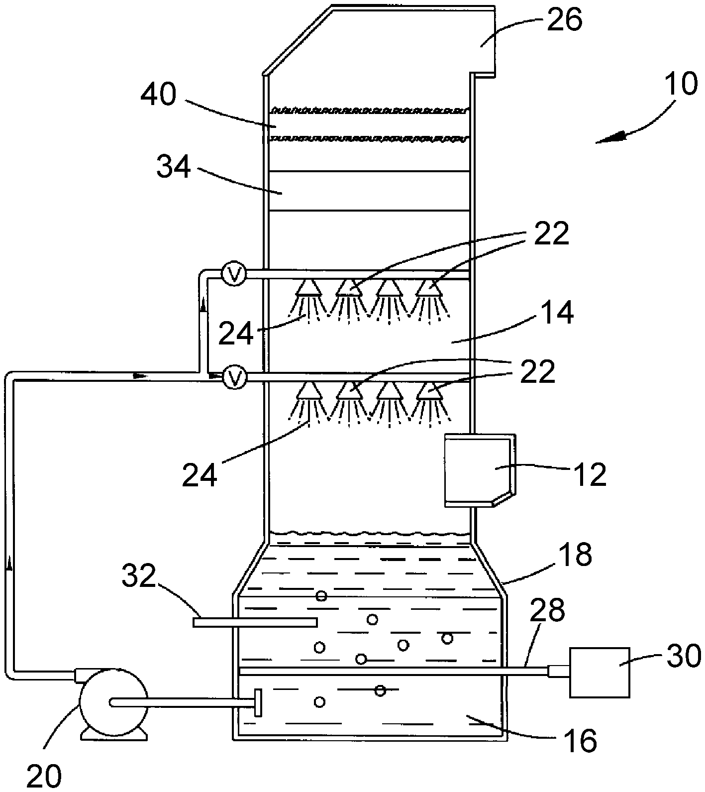
[0011] FIG. 1 schematically represents a cross-sectional view of an absorber of a wet flue gas desulfurization system configured in accordance with a nonlimiting embodiment of the present invention.
DETAILED DESCRIPTION OF THE INVENTION
[0012] Disclosed herein are wet flue gas desulfurization (FGD) systems equipped with an absorber for contacting a flue gas with a scrubbing liquid to remove sulfur dioxide and potentially other acidic gases from the flue gas, and further include the injection of elemental sulfur into the scrubbing solution to produce a thiosulfate (S.sub.2O.sub.3.sup.-2) byproduct, for example, ammonium thiosulfate ((NH.sub.4).sub.2S.sub.2O.sub.3; or H.sub.8N.sub.2O.sub.3S.sub.2).
[0013] Ammonium thiosulfate, which has various uses in industry, has been typically produced by one of two methods. One method is to mix solutions of ammonium sulfate and sodium thiosulfate, followed by cooling and filtration of the resultant products, which are a solid sodium sulfate precipitant and the highly soluble ammonium thiosulfate. The second process utilizes hydrogen sulfide, sulfur dioxide, ammonia, and oxygen to generate ammonium thiosulfate. The present invention provides for the production of ammonium thiosulfate as a valuable byproduct of a desulfurization process. As such, the process disclosed herein does not require feed streams conventionally required to produce ammonium thiosulfate, and instead can be incorporated into existing processes intended to provide the environmental advantage of removing acidic gases from waste streams, including but not limited to utility and industrial flue gases.
[0014] FIG. 1 schematically represents a nonlimiting embodiment of a flue gas absorber 10 of a type that can be employed by the invention. The absorber 10 is generally of the type that scrubs flue gases produced by utility and industrial facilities that burn fossil fuels, as well as other processes that result in a flue gas that contains sulfur dioxide and often other acidic gas, nonlimiting examples of which include hydrogen chloride and hydrogen fluoride. The absorber 10 includes a contact region 14 in which a contact medium is brought into contact with a flue gas that enters the absorber 10 through an inlet duct 12. The contact medium is an alkaline liquor, typically a slurry or solution, referred to herein as a scrubbing liquid 16 as a matter of convenience. The scrubbing liquid 16 is shown as being collected in a reaction tank 18 at a lower end of the absorber 10, and circulated with a pump 20 to the contact region 14, where devices 22 (as nonlimiting examples, spray nozzles) atomize and disperse the scrubbing liquid 16 as fine droplets 24 within the contact region 14 to promote contact with the flue gas and absorb acidic gases therefrom.
[0015] After being scrubbed by the scrubbing liquid 16, the scrubbed (desulfurized) flue gas continues upward from the contact region 14 to enter a section of the absorber 10 intended to remove liquid carryover of the scrubbing liquid 16, for example, droplets and/or fine aerosol particulates that are typically entrained in the scrubbed flue gas. In FIG. 1, the scrubbed flue gas enters a bulk liquid entrainment separator 34, which is intended to remove large droplets from the flue gas by causing the droplets to impinge one or more surfaces that collect the droplets and enable the collected liquid to be drained from the absorber 10. FIG. 1 schematically represents a mist eliminator 40 located above the entrainment separator 34 to further remove droplets of the scrubbing liquid from the scrubbed flue gas, and particularly fine droplets and/or aerosol particulates that the entrainment separator 34 did not or cannot remove from the scrubbed flue gas. Various designs for entrainment separators and mist eliminators that are suitable for use in the absorber 10 are conventional or otherwise known in the art, and therefore will not be discussed in any detail here. After passing through the mist eliminator 40, the desulfurized flue gas is eventually released to atmosphere through a chimney 26 or other suitable structure.
[0016] In the present invention, in which ammonium thiosulfate ((NH.sub.4).sub.2S.sub.2O.sub.3) is the or an intended byproduct, the scrubbing liquid 16 represented in FIG. 1 is an aqueous solution that contains ammonium sulfate and the embodiment of the absorber 10 is further equipped with means for injecting elemental sulfur and ammonia (anhydrous or aqueous (ammonium hydroxide)) into the scrubbing liquid 16 that has collected in the reaction tank 18 below the contact region 14. As part of the chemical reaction to meet the required sulfur levels for producing ammonium thiosulfate, FIG. 1 represents elemental sulfur as being introduced directly into the scrubbing liquid 16 within the tank 18 with an injector 28 connected to a source 30 of elemental sulfur. In FIG. 1, ammonia is represented as being introduced into the tank 18 with a separate injector 32. In addition to being required for the reaction that produces ammonium thiosulfate, ammonia also serves to increase the efficiency of sulfur dioxide removal from the scrubbing liquid 16 by reducing the acidity of the scrubbing liquid 16, which becomes more acidic with the absorption of sulfur dioxide. A reaction occurring in the scrubbing liquid 16 collected in the tank 18 is summarized as follows.
2NH.sub.3+SO.sub.2+H.sub.2O+S.fwdarw.(NH.sub.4).sub.2S.sub.2O.sub.3
As noted above, the ammonia is present as a result of the anhydrous and/or aqueous ammonia introduced into the scrubbing liquid 16 by the injector 32, the sulfur dioxide is present in the scrubbing liquid 16 as a result of being absorbed from the flue gases, the water is present as a constituent of the aqueous ammonium sulfate solution of the scrubbing liquid 16, and the elemental sulfur is introduced into the scrubbing liquid 16 by the injector 28. A portion of the scrubbing liquid 16 can be removed from the tank 18 and dewatered to precipitate ammonium thiosulfate, which can then be sold as a valuable byproduct of the FGD process.
[0017] In preferred embodiments, the absorber 10 is specifically designed and operated, by controlling such operating parameters as temperature, pH and sulfur concentration, to generate ammonium thiosulfate without producing or yielding a secondary byproduct. The reaction that produces ammonium thiosulfate does not require a reaction tank of a size (volume) typically required of prior ammonia-based WFGD systems, allowing pre-existing calcium-, sodium-, and ammonia-based WFGD systems to be converted to produce ammonium thiosulfate. As such, the absorber 10 may be part of a new or pre-existing ammonia-based WFGD system, or be installed as an upgrade and retrofit of a pre-existing calcium-based (lime/limestone) or sodium-based WFGD system.
[0018] While the invention has been described in terms of a specific or particular embodiment, it should be apparent that alternatives could be adopted by one skilled in the art. For example, the absorber 10 and its components could differ in appearance and construction from the embodiment described herein and shown in the drawing, functions of certain components of the absorber 10 could be performed by components of different construction but capable of a similar (though not necessarily equivalent) function, various materials could be used in the fabrication of the absorber 10 and/or its components, and the absorber 10 could be installed in various types of FGD systems. In addition, the invention encompasses additional or alternative embodiments in which one or more features or aspects of a particular embodiment could be eliminated. Accordingly, it should be understood that the invention is not necessarily limited to any embodiment described herein or illustrated in the drawing. It should also be understood that the phraseology and terminology employed above are for the purpose of describing the disclosed embodiment, and do not necessarily serve as limitations to the scope of the invention. Therefore, the scope of the invention is to be limited only by the following claims.
* * * * *
D00000
D00001
XML
uspto.report is an independent third-party trademark research tool that is not affiliated, endorsed, or sponsored by the United States Patent and Trademark Office (USPTO) or any other governmental organization. The information provided by uspto.report is based on publicly available data at the time of writing and is intended for informational purposes only.
While we strive to provide accurate and up-to-date information, we do not guarantee the accuracy, completeness, reliability, or suitability of the information displayed on this site. The use of this site is at your own risk. Any reliance you place on such information is therefore strictly at your own risk.
All official trademark data, including owner information, should be verified by visiting the official USPTO website at www.uspto.gov. This site is not intended to replace professional legal advice and should not be used as a substitute for consulting with a legal professional who is knowledgeable about trademark law.