Annular Seal For Spherical Blowout Preventer
Pendleton; Gary
U.S. patent application number 16/160326 was filed with the patent office on 2020-04-16 for annular seal for spherical blowout preventer. The applicant listed for this patent is Axon Pressure Products, Inc.. Invention is credited to Gary Pendleton.
| Application Number | 20200115985 16/160326 |
| Document ID | / |
| Family ID | 70159417 |
| Filed Date | 2020-04-16 |


View All Diagrams
| United States Patent Application | 20200115985 |
| Kind Code | A1 |
| Pendleton; Gary | April 16, 2020 |
ANNULAR SEAL FOR SPHERICAL BLOWOUT PREVENTER
Abstract
A method for closing an annular BOP and restricting flow from the wellbore through the BOP using hardened segments of the packing element is provided. The method relies on a translation motion (e.g., at least partially in a tangential direction) of the hardened segments, rather than a purely radial motion of the segments. The translation motion is a spiral motion of the hardened segments with respect to a longitudinal axis of the packing element. An elastomer is bonded to the hardened segments, and the translation action of the hardened segments supports the elastomer to close to a zero position and affect a fluid tight seal of the bore.
| Inventors: | Pendleton; Gary; (Durham, GB) | ||||||||||
| Applicant: |
|
||||||||||
|---|---|---|---|---|---|---|---|---|---|---|---|
| Family ID: | 70159417 | ||||||||||
| Appl. No.: | 16/160326 | ||||||||||
| Filed: | October 15, 2018 |
| Current U.S. Class: | 1/1 |
| Current CPC Class: | E21B 33/06 20130101 |
| International Class: | E21B 33/06 20060101 E21B033/06 |
Claims
1. A method, comprising: pressing on a packing element of an annular blowout preventer (BOP) via a piston of the annular BOP, wherein the packing element comprises: an array of hardened segments arranged circumferentially about a longitudinal axis of the packing element; an actuator plate; and an elastomer disposed between and bonded to the actuator plate and the array of hardened segments; and moving the array of hardened segments in a spiral configuration relative to the longitudinal axis of the packing element to reduce a size of or fully close a bore through the packing element.
2. The method of claim 1, wherein each hardened segment of the array of hardened segments comprises a leading edge oriented substantially tangential to the bore through the packing element, and wherein moving the array of hardened segments in a spiral configuration comprises moving each hardened segment in a tangential direction relative to the bore and in a radially inward direction with respect to the axis of the packing element.
3. The method of claim 1, wherein the annular BOP comprises a BOP head with a concave semi-spherical internal surface formed therein, wherein each of the hardened segments comprise a convex external surface, and wherein pressing on the packing element engages the convex external surfaces of the array of hardened segments with the concave semi-spherical internal surface.
4. The method of claim 3, wherein the concave semi-spherical internal surface of the BOP head guides the array of hardened segments to move in the spiral configuration.
5. The method of claim 1, further comprising guiding the movement of the array of hardened segments in the spiral configuration via the actuator plate, wherein the actuator plate comprises slots formed therein, and wherein each hardened segment comprises a support arm extending therefrom and seated in a corresponding one of the slots in the actuator plate.
6. The method of claim 1, comprising moving the array of hardened segments in the spiral configuration to fully close the bore through the packing element.
7. The method of claim 6, further comprising sealing the bore through the packing element via the elastomer.
8. The method of claim 7, wherein the elastomer seals the bore through the packing element before the array of hardened segments fully close the bore through the packing element.
9. The method of claim 1, wherein each hardened segment comprises a wedge shape with a leading edge facing the axis of the packing element, a trailing edge facing away from the axis of the packing element, and complementary stepped profiles formed along the leading edge and the trailing edge, wherein the trailing edge of each hardened segment receives and guides the leading edge of an adjacent hardened segment.
10. The method of claim 1, comprising providing variable bore sealing of the annular BOP via the packing element.
11. A packing element for an annular BOP, the packing element comprising: an array of hardened segments arranged circumferentially about a longitudinal axis of the packing element; an actuator plate; and an elastomer disposed between and bonded to the actuator plate and the array of hardened segments; wherein the array of hardened segments is movable in a spiral configuration relative to a longitudinal axis of the packing element to reduce a size of or fully close a bore through the packing element.
12. The packing element of claim 11, wherein each of the hardened segments comprises a leading edge oriented substantially tangential to the bore through the packing element.
13. The packing element of claim 12, wherein the array of hardened segments is movable in a spiral configuration whereby each hardened segment moves in a tangential direction relative to the bore and in a radially inward direction with respect to the axis of the packing element.
14. The packing element of claim 11, wherein each of the hardened segments comprise a convex external surface configured to engage with a complementary concave semi-spherical internal surface formed in a BOP head of the annular BOP.
15. The packing element of claim 11, wherein each hardened segment comprises a rounded wedge shape with a leading edge facing the axis of the packing element, a trailing edge facing away from the axis of the packing element, and a convex external surface extending between the leading and trailing edges.
16. The packing element of claim 15, wherein each hardened segment comprises a stepped profile formed along the leading edge and a complementary stepped profile formed along the trailing edge, wherein the trailing edge of each hardened segment receives and guides the leading edge of an adjacent hardened segment.
17. The packing element of claim 11, wherein the actuator plate comprises slots formed therein, and wherein each hardened segment comprises a support arm extending therefrom and seated in a corresponding one of the slots in the actuator plate.
18. The packing element of claim 17, wherein each of the slots is aligned in a tangential orientation with respect to the bore through the packing element.
19. The packing element of claim 11, wherein each hardened segment comprises a downward facing surface with an extension extending therefrom, wherein the elastomer is bonded to the concave surface and to the extension.
20. The packing element of claim 11, wherein movement of the array of hardened segments in the spiral configuration forces the elastomer to deform radially inward.
Description
TECHNICAL FIELD
[0001] Embodiments of the present disclosure relate generally to annular blowout preventers, and more specifically, to an improved seal for annular blowout preventers.
BACKGROUND
[0002] This section is intended to introduce the reader to various aspects of art that may be related to various aspects of the present disclosure, which are described and/or claimed below. This discussion is believed to be helpful in providing the reader with background information to facilitate a better understanding of the various aspects of the present disclosure. Accordingly, it should be understood that these statements are to be read in this light and not as admissions of prior art.
[0003] Blowout preventers are used extensively throughout the oil and gas industry. Typical blowout preventers include a main body to which are attached various types of ram units or packing units. The two categories of blowout preventers that are most prevalent are ram blowout preventers and annular blowout preventers. Blowout preventer stacks frequently utilize both types, typically with at least one annular blowout preventer stacked above several ram blowout preventers. A blowout preventer stack may be secured to a wellhead and may provide a means for sealing the well in the event of a system failure.
[0004] Annular blowout preventers can close around a drill string, casing, and even non-cylindrical objects (e.g., a kelly). Drill pipe, including larger-diameter tool joints (e.g., threaded connectors) can be "stripped" (i.e., moved vertically while pressure is contained below) through an annular blowout preventer by careful control of the hydraulic closing pressure. Annular blowout preventers are also effective at maintaining a seal around drill pipe, even as it rotates during drilling. Regulations typically require that an annular blowout preventer is able to completely close a wellbore.
[0005] Annular blowout preventers generally include annular packing units or packing elements made at least partially from elastomeric material. Upon activation of the annular BOP, the packing element seals the wellbore. The annular blowout preventer typically includes a piston that is actuated (e.g., through pressurized air or fluid) into engagement with the elastomeric packing element. Such activation of the annular packing element compresses the elastomeric material within the annular space until the elastomeric material deforms in a radially inward direction to ultimately seal the wellbore. Metallic or other hardened segments are often included in the annular packing element to help close off the wellbore and guide the elastomer. Annular blowout preventers have two moving parts, the piston and the packing element, making them simple to operate and easy to maintain.
[0006] Existing annular packing elements can have issues with rubber loss and decreased sealing performance when used over long periods of time. It is now recognized that an annular blowout preventer packing unit with improved sealing function and reduced elastomer loss over time is desired.
SUMMARY
[0007] In accordance with an embodiment of the present disclosure, a method includes pressing on a packing element of an annular blowout preventer (BOP) via a piston of the annular BOP. The packing element includes an array of hardened segments arranged circumferentially about a longitudinal axis of the packing element, an actuator plate, and an elastomer disposed between and bonded to the actuator plate and the array of hardened segments. The method also includes moving the array of hardened segments in a spiral configuration relative to the longitudinal axis of the packing element to reduce a size of or fully close a bore through the packing element.
[0008] In accordance with another embodiment of the present disclosure, a packing element for an annular blowout preventer (BOP) includes an array of hardened segments arranged circumferentially about a longitudinal axis of the packing element, an actuator plate, and an elastomer disposed between and bonded to the actuator plate and the array of hardened segments. The array of hardened segments is movable in a spiral configuration relative to a longitudinal axis of the packing element to reduce a size of or fully close a bore through the packing element
BRIEF DESCRIPTION OF THE DRAWINGS
[0009] For a more complete understanding of the present disclosure and its features and advantages, reference is now made to the following description, taken in conjunction with the accompanying drawings, in which:
[0010] FIG. 1 is a schematic cross-sectional view of an annular blowout preventer, in accordance with an embodiment of the present disclosure;
[0011] FIG. 2 is a perspective partial cutaway view of portions of the annular blowout preventer of FIG. 1, in accordance with an embodiment of the present disclosure;
[0012] FIGS. 3A and 3B are perspective views of a hardened segment of the annular blowout preventer of FIG. 2, in accordance with an embodiment of the present disclosure;
[0013] FIG. 4 is a perspective view of a lower plate of the annular blowout preventer of FIG. 2, in accordance with an embodiment of the present disclosure;
[0014] FIG. 5 is a perspective cutaway view of a blowout preventer head of the annular blowout preventer of FIG. 2, in accordance with an embodiment of the present disclosure;
[0015] FIGS. 6A-6G are a series of perspective partial cutaway views and top partial cutaway views of the portions of the annular blowout preventer of FIG. 2 being closed, in accordance with an embodiment of the present disclosure; and
[0016] FIGS. 7A-7F are a series of cross-sectional views of the annular blowout preventer of FIG. 2 with an elastomer portion being closed, in accordance with an embodiment of the present disclosure.
DETAILED DESCRIPTION
[0017] One or more specific embodiments of the present disclosure will be described below. In an effort to provide a concise description of these embodiments, not all features of an actual implementation are described in the specification. It should be appreciated that in the development of any such actual implementation, as in any engineering or design project, numerous implementation-specific decisions must be made to achieve the developers' specific goals, such as compliance with system-related and business-related constraints, which may vary from one implementation to another. Moreover, it should be appreciated that such a development effort might be complex and time consuming, but would nevertheless be a routine undertaking of design, fabrication, and manufacture for those of ordinary skill having the benefit of this disclosure.
[0018] Generally, embodiments of the present disclosure are directed to a spherical packing element that may be utilized in annular blowout preventers. Existing spherical packing elements function such that, as the piston rises, the packing element is thrust upward against a curved head which constricts the packing element inward. There are some issues with commonly used spherical annular packing elements. Typically, the packing elements have wedge-style inserts that are embedded in an elastomer. These inserts impinge on the inner surfaces of the curved annular head as the piston rises, helping deform the elastomer toward the wellbore center. In existing packing elements, the wedge inserts are radially spaced, and have to be designed to close to a zero or near zero position.
[0019] Unfortunately, in the open position, the spacing between the wedge inserts of the packing element is increased, and consequently elastomer (rubber) can become trapped between the wedge inserts. This elastomer is increasingly compressed as the wedge inserts draw radially to the zero (closed) position. The compressed elastomer often extrudes out between the metal inserts, in a slightly uncontrolled manner, i.e., the metal elements are dislocated depending on the stress levels built within the rubber. Due to the significant stresses built up within the elastomer (both in compression and tension), shearing of the rubber can occur, especially after several operation cycles. This can cause undesirable degradation of the elastomer and, if unchecked, inefficient operation of the BOP.
[0020] The disclosed spherical packing element overcomes the drawbacks associated with existing packing elements. Specifically, the disclosed packing element is arranged such that vital sealing surfaces of the elastomer cannot become caught between the metal inserts of the packing element. The hardened inserts in the disclosed embodiments are tangentially, rather than radially, oriented and are configured to be closed in a spiral configuration that prevents extrusion of the elastomer between the edges of the inserts.
[0021] Presently disclosed embodiments are directed to a method for closing an annular BOP and restricting flow from the wellbore through the BOP purely using the hardened segments of the packing element. The method relies on a translation motion (e.g., at least partially in a tangential direction) of the hardened segments, rather than a purely radial motion of the segments. In present embodiments, for example, the translation motion is generally a spiral motion of the hardened segments with respect to a longitudinal axis of the packing element.
[0022] The hardened segments of the packing element do not themselves provide a fluid tight seal. An elastomer is internally bonded to the hardened segments, and the translation action of the hardened segments support the elastomer to close to a zero position and affect a fluid tight seal of the bore. The disclosed translation motion generally provides a tangential face of each segment to the bore of the packing element, thereby allowing gradual restriction of the size of the bore from full bore to a zero (closed and sealed) position. With the disclosed method, movement of the hardened segments of the annular packing element can cater from full bore down to zero position sealing, thereby providing variable bore sealing.
[0023] Turning now to the drawings, FIG. 1 is a schematic cross-sectional view of an annular BOP 10 which may employ the disclosed annular packing element 12. The annular BOP 10 may include a housing 14, a piston 16 disposed in an annular chamber 18 within the housing 14, and the annular packing element 12. The illustrated annular BOP 10 may be combined with a number of other BOP units arranged in a vertical stack. Such a stack of units is commonly referred to as a BOP stack, and may include one or more ram-type BOPs (not shown) as well as one or more annular BOPs (e.g., 10). As such, FIG. 1 is merely representative of a single annular BOP 10, which may be combined with any number of other BOPs not shown.
[0024] The annular BOP 10 generally includes a vertical bore 20 extending therethrough, and a tubular 22 (or other equipment component) may be disposed within the vertical bore 20. The tubular 22 may form part of a drillpipe, casing, riser, liner, production tubing, coiled tubing, or any other string of tubular that is being positioned within a wellbore below the BOP 10. The BOP 10 is designed to lock the tubular 22 in place and seal the tubular 22 against large pressures from downhole in the event of a kick or other unanticipated event.
[0025] The housing 14 may enclose the other components of the annular BOP 10. The housing 14 may be one continuous component or may include two or more outer housing components coupled together via appropriate fasteners such as bolts. An upper portion 24 of the housing 14, which may be a separate element, may have a curved or spherical shape for accommodating the annular packing element 12. Inside the housing 14, the annular packing element 12 is generally positioned above the piston 16, and the piston 16 is at least partially seated within the annular chamber 18.
[0026] One or more walls 26 located inside the housing 14 may define the annular chamber 18. As shown, for example, the annular BOP 10 may include a cylindrical wall 26 coupled to and extending upward from a bottom surface of the housing 14 to form a radially internal wall of the annular chamber 18. The rest of the annular chamber 18 may be defined by an external side wall of the housing 14 and the bottom surface of the housing 14, as shown. However, other arrangements of walls, surfaces, and similar components may define the annular fluid chamber 18 in other embodiments. Seals 28 are generally located between the walls of the chamber 18 and the piston 16 disposed therein.
[0027] Actuating the annular BOP 10 to close off and/or seal the tubular 22 involves directing pressurized fluid into the chamber 18. This pressurized fluid forces the piston 16 to move upward within the chamber 18. An upper surface 30 of the piston 16 presses directly into the annular packing element 12 in response to this upward movement. This force from the piston 16 compresses the packing element 12 against the surfaces of the housing 14, which direct the packing element 12 to collapse radially inward into locking/sealing engagement with the tubular 22 extending through the BOP 10.
[0028] As illustrated, the packing element 12 may be a spherical annular packing element having a rounded or spherical upper surface shape. The packing element 12 of FIG. 1 may include hardened segments bonded to an elastomer and a lower actuator plate, and the arrangement of these components are such that the hardened packing element segments move in a spiral (i.e., at least partially tangential) direction rather than a purely radial direction to close and/or seal against the tubular 22. As such, the disclosed packing element 12 may provide an enhanced method of annular BOP element closure that prevents undesirable elastomer extrusion and degradation.
[0029] FIGS. 2-5 illustrate the presently disclosed annular packing element 12 and its constituent components in greater detail. FIG. 2 illustrates certain non-elastomer components of the packing element 12 along with a BOP head 100, which may form part (e.g., upper portion 24) of the BOP housing 14 of FIG. 1. As mentioned above, the disclosed annular packing element 12 includes a plurality of hardened segments 110, an elastomer (not shown in FIG. 2), and an actuator plate 114. The hardened segments 110 are arranged in a circumferentially spaced array and are each coupled to an upper surface of the elastomer. The hardened segments 110 form an upper bound of the overall packing element 12. When the packing element 12 of FIG. 2 is assembled into the BOP of FIG. 1, for example, these hardened segments 110 will be the portions of the packing element 12 that directly interface with the BOP head 100 during actuation of the annular BOP.
[0030] The BOP head 100 is illustrated as having one half of the BOP head 100 cut away so that the packing element 12 is visible. It will be understood that the full BOP head 100 extends a full 360 degrees around a longitudinal axis 116 of the packing element 12. In this way, the full BOP head 100 entirely encircles the packing element 12 during operation of the annular BOP.
[0031] As discussed in greater detail below, the hardened segments 110 have a rounded shape at their upper surfaces to form a spherical annular packing element 12. The spherical shape formed by the hardened segments 110 taken together matches that the of the inside of the BOP head 100. The illustrated embodiment of the packing element 12 is made up of twelve individual hardened segments 110. However, it should be noted that any desired number of multiple segments can be used depending on the size constraints of the annular BOP. The packing element 12 also includes the lower actuation plate 114, which is driven by the BOP piston. As discussed in greater detail below, the hardened segments 110 each include support arms 316 that are located within the lower plate 114.
[0032] The hardened segments 110 are located within the spherical BOP head 100, and they are activated with the aid of the lower plate 114 in response to pressure from the BOP piston. The lower plate 114 both impinges on the hardened segments 110 and helps to guide their trajectory in conjunction with the spherical profile of the inside of the BOP head 100. The elastomer (again, not shown in FIG. 2), once bonded into position, provides both sealing of the bore through the annular BOP and a spring resistance to the hardened segments 110, ensuring the segments 110 are pressed to the spherical feature of the BOP head 100 throughout the entire operation.
[0033] FIGS. 3A and 3B provide two detailed views of an individual one of the plurality of hardened segments 110 used in the packing element 12 of FIG. 2. Each of the hardened segments 110 that make up the packing element 12 has the same relative shape and size of the individual hardened segment 110 of FIGS. 3A and 3B; these individual pieces fit together to form a movable upper portion of the packing element.
[0034] As shown in FIGS. 3A and 3B, the hardened segment 110 includes a main wedge-shaped feature 300. The wedge-shaped feature 300 has a leading edge 302 and a trailing edge 304, and the leading edge 302 and trailing edge 304 meet at a point 306. The wedge-shaped feature 300 is slightly rounded to provide a convex shaped outer face 308. This convex shaped outer face 308 is designed to directly contact the spherical feature of the BOP head (100 of FIG. 2). Although the wedge-shaped feature 300 is curved, the leading edge 302 may extend in a generally "straight" direction, i.e., a projection of a straight line onto the curved outer surface 308. The trailing edge 304 may extend in a generally "straight" direction for part of the edge 304, before forming a rounded corner 310 connecting back to the leading edge 302. This rounded corner 310 is where the leading edge 302 and the trailing edge 304 meet opposite the point 306.
[0035] When the multiple hardened segments 110 are fully assembled in the packing element (e.g., of FIG. 2), the leading edge 302 of each hardened segment 110 faces (i.e., is radially closer to) the longitudinal axis (116 of FIG. 2) of the packing element, while the trailing edge 304 of each hardened segment 110 faces away from (i.e., is radially father from) the axis of the packing element.
[0036] As illustrated, the hardened segment 110 may be machined such that the leading and trailing edges 302 and 304 each include a stepped or undercut profile. For example, the leading edge 302 is formed by only an upper portion 312 of the full thickness of the wedge-shaped feature 300, while a lower portion of the wedge is cut out at this edge 302. Similarly, but reversed, the trailing edge 304 is formed by only a lower portion 314 of the full thickness of the wedge-shaped feature 300, while an upper portion of the wedge is cut out at this edge 304. This way, the multiple hardened segments 110 can be placed one over the other, with the leading edge 302 of one hardened segment 110 overlapping the trailing edge 304 of an adjacent hardened segment 110. This arrangement of the array of hardened segments 110 is illustrated in FIG. 2. The undercut portions of the trailing edges 304 of the segments 110 help to guide the leading edges 302 of the adjacent segments 110 as the segments 110 move to open or close the bore through the annular BOP. This arrangement also helps to keep the elastomer from extruding between adjacent hardened segments 110, since the hardened segments 110 are already overlapping each other except at the center/top portion of the packing element.
[0037] When assembled together within the packing element of FIG. 2, each of the hardened segments 110 is positioned such that their leading edge 302, near the point 306 of the wedge-shaped feature 300, defines an edge of a bore 600 through the packing element 12. The bore 600 can be opened or closed via translational movement of the multiple hardened segments 110. The bore 600 can even be fully closed via translational movement of the hardened segments 110 from their positions in FIG. 2 to positions where the wedge-shaped features 300 come together at a point at the top of the spherical packing element 12. The direction of movement of each hardened segment 110 toward the closed position has a tangential component with respect to the bore through the packing element and a radial component in a direction toward the axis 116. As the segments 110 move together in unison, they change the size of the bore through the packing element 12. The leading edge 302 proximate the point 306 of each segment 110 remains tangential to the bore throughout movement of the packing element.
[0038] Turning back to FIGS. 3A and 3B, each hardened segment 110 may also include a lever arm 316 extending therefrom in a downward direction. The lever arm 316 may be engaged with the lower plate (114 of FIG. 2) of the packing element and guided in a corresponding slot of the lower plate. The hardened segments 110 may each include an extension 318 extending downward from a lower surface 320 of the wedge-shaped feature 300. This extension 318 may support and help to move the elastomer of the packing element for sealing the wellbore. The elastomer may be bonded directly to the lower surface 320 of the wedge-shaped feature 300 and to one or both sides of the extension 318. The extension 318 may help to urge the elastomer in a radially inward direction as desired to seal the annular BOP during closing of the annular packing element.
[0039] The hardened segments 110 may be constructed from sufficiently hard metallic material including, but not limited to, steel. The material of the segments 110 may be any material that meets the API 164 4th edition 5.3 pressure-containing parts requirements for 60 Ksi to 75 Ksi (see table 1 below) with a chemical composition in accordance with the steel composition limits for pressure-containing parts per table 2 below.
TABLE-US-00001 TABLE 1 Elongation in Reduction of Yield Strength 0.2% Offset Tensile Strength 50 mm Area Material min. min. min. min. Designation MPa (psi) MPa (psi) % % 36K 248 (36,000) 483 (70,000) 21 none specified 45K 310 (45,000) 483 (70,000) 19 32 60K 414 (60,000) 586 (85,000) 18 35 75K 517 (75,000) 655 (95,000) 18 35 Non-standard As specified As specified As specified As specified 15 20 Materials NOTE Information on strength of materials at elevated temperature is found in API 6A and API TR 6MET.
TABLE-US-00002 TABLE 2 Carbon and Low-alloy Martensitic Stainless Steels Limit Steels Limit % Mass Fraction % Mass Fraction Alloying Element (Maximum) (Maximum) Carbon 0.45 0.15 Manganese 1.80 1.00 Silicon 1.00 1.50 Phosphorus 0.025 0.025 Sulphur 0.025 0.025 Nickel 1.00 4.50 Chromium 2.75 11.0 to 14.0 Molybdenum 1.50 1.00 Vanadium 0.30 N/A
[0040] FIG. 4 provides a more detailed view of the lower actuator plate 114 of the packing element 12 of FIG. 2. The lower plate 114 is annular is shape, and includes a flat downward facing surface 400 that is in engagement with (or integral with) the piston of the annular BOP. The lower plate 114 may include an upwardly projecting feature 402 with a unique shape to function with the rest of the spherical packing element (12 of FIG. 2). The upwardly projecting feature 402 may have an annular shape with an inner diameter 404 that is larger than an inner diameter 406 of the downward facing surface 400. The radially outer edge of the upwardly projecting feature 402 may have a series of slots 408 formed therein. The slots 408, as illustrated, are linear. Each slot 408 may oriented in a specific manner with respect to a bore formed through the packing element. The directions in which the slots 408 are oriented correspond to a direction that is substantially tangent to the bore through the packing element at a point that is aligned in a radial direction with a radially innermost edge 410 of the slot 408. However, it should be noted that other relative orientations of the slots 408 to the bore are possible. For example, the slots 408 may be aligned in a direction that has both a tangential component with respect to the bore of the packing element as well as a radial component with respect to the longitudinal axis of the packing element. Although not shown, in other embodiments the slots 408 may be curved.
[0041] The slots 408 help to guide the lever arms (316 of FIGS. 3A and 3B) of the hardened segments (110 of FIG. 2). Each slot 408 receives a lever arm from a corresponding one of the array of hardened segments of the packing element. As the lower plate 114 pushes upward on the hardened segments, engaging the hardened segments with the above spherical BOP head, the lever arms may rotate within the slots 408 from a position where the lever arms are generally vertically aligned to a position where the lever arms are collapsed in a near horizontal direction within the slots 408.
[0042] The lower plate 114 includes an upper facing annular surface 412 and a radially inner wall 414 of the upwardly projecting feature 402. The elastomer of the packing element may be bonded directly to the upper facing annular surface 412 and the radially inner wall 414 of the lower plate 114.
[0043] The lower plate 114 may be formed from a single piece of material, and the plate 114 may be constructed from any sufficiently hard metallic material including, but not limited to, steel. The material of the lower plate 114 may be any material that meets the API 164 4th edition 5.3 pressure-containing parts requirements for 36 Ksi to 75 Ksi (see table 1 above) with a chemical composition in accordance with the steel composition limits for pressure-containing parts per table 2 above.
[0044] FIG. 5 is a cutaway view of the BOP head 100 of the annular BOP for use with the disclosed packing element. The BOP head 100 has a spherical feature 500 formed therein, this spherical feature 500 being a concave semi-spherical internal surface formed in the BOP head 100. The convex shaped external surfaces of the hardened segments of the packing element are pressed against this spherical feature 500 of the BOP head 100 when the piston presses the lower plate (and attached hardened segments) in an upward direction in the BOP. The concave semi-spherical internal surface 500 of the BOP head 100 guides the array of hardened segments to move in a spiral configuration to close the bore through the BOP. The BOP head 100 also includes a bore 502 formed therethrough at a top surface of the BOP head 100. The bore 502 defines the maximum possible diameter of the bore through the annular BOP. The disclosed packing element is used to change the diameter of the bore through the BOP from this maximum diameter to a reduced diameter as needed (e.g., to perform stripping or sealing against a drill pipe), or to a zero diameter closed position (to close and seal the wellbore).
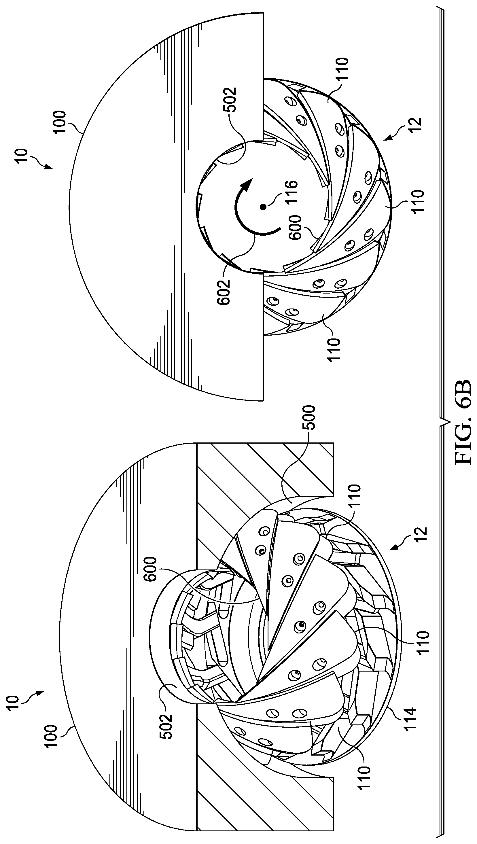
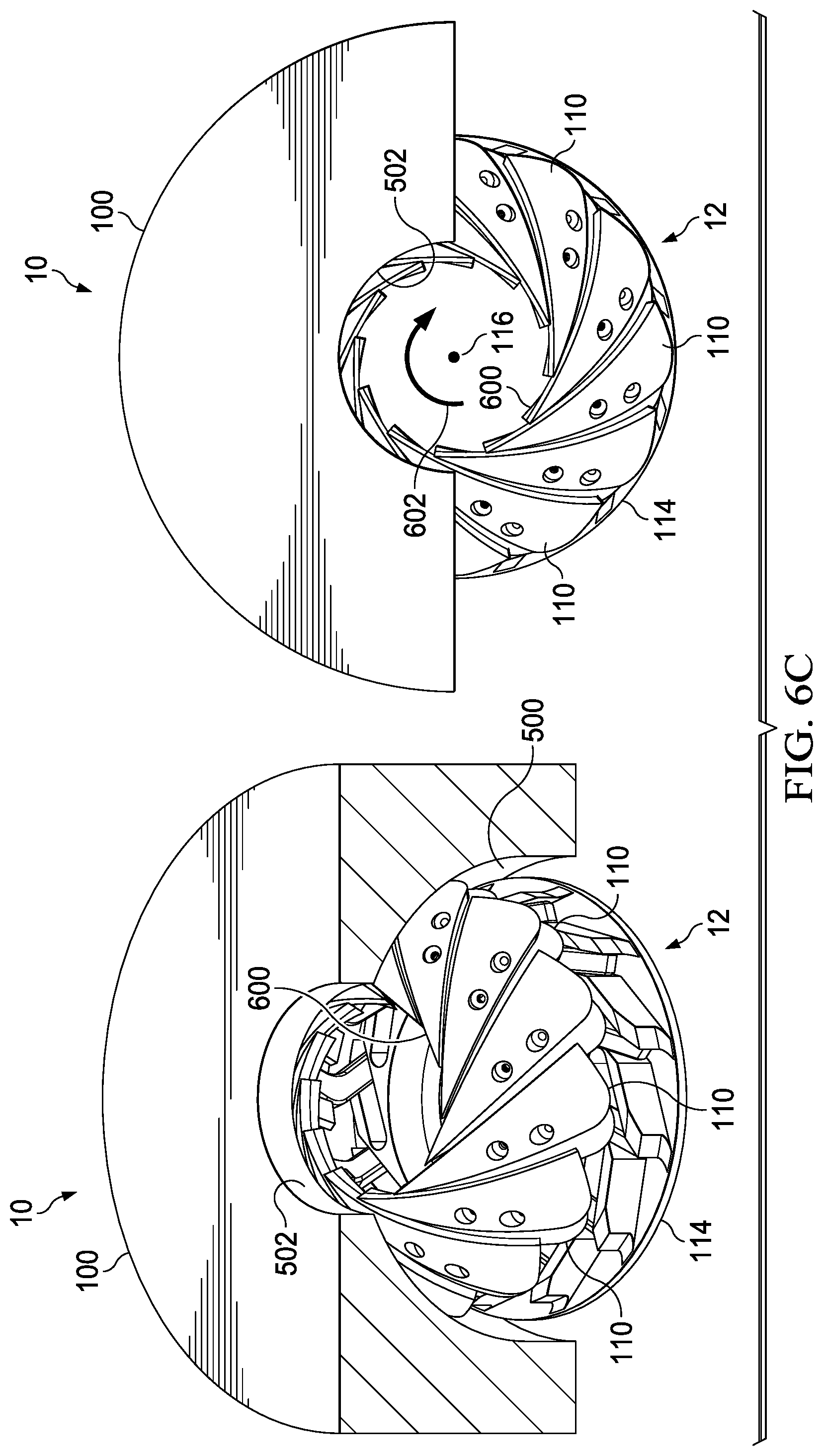
[0045] FIGS. 6A-6G illustrate the operation of reducing and eventually closing the bore through the annular BOP 10 in accordance with an embodiment of the present disclosure. FIGS. 6A-6G illustrate this operation with the BOP head 100 partially cut away, and without showing the elastomer of the packing element 12.
[0046] In FIG. 6A, the annular BOP 10 is in full bore operation, or a fully open position. That is, the hardened segments 110 are in positions such that the bore 600 formed through the annular packing element 12 via the array of hardened segments 110 has a larger diameter than the diameter of the bore 502 through the BOP head 100 (and corresponding bore through the lower plate 114). As such, the full bore of the BOP is the size of the bore 502 through the BOP head 100.
[0047] FIG. 6B shows the annular BOP 10 being actuated to begin the closing operation. The piston (not shown) of the BOP presses upward on the lower plate 114, which in turn presses the hardened segments 110 upward and into contact with the spherical feature 500 of the BOP head 100. This contact on the hardened segments 110 causes the hardened segments 110 to move in a spiral configuration (arrow 602) with respect to the longitudinal axis 116 of the packing element 12. During this movement, the leading edge (302 of FIGS. 3A and 3B) of each hardened segment 110 remains substantially tangential to the bore 600 of the packing element 12. Moving the array of hardened segments 110 in the spiral configuration (arrow 602) involves moving each hardened segment 110 in a tangential direction relative to the bore 600 and in a slightly radially inward direction with respect to the axis 116. The hardened segments 110 are collapsed inward on each other as they tangentially slide past each other in response to force from the lower plate 114 below and the spherical feature of the BOP head 100 above. The lever arms (316 of FIGS. 3A and 3B) begin to rotate to guide the hardened segments 110 as they collapse radially inward and downward against the elastomer.
[0048] FIG. 6B shows the BOP 10 when it has reached a position where the bore 600 of the annular packing element 12 is approximately equal to the bore 502 through the BOP head 100. Continued upward force on the lower portion 114 causes continued closure of the annular packing element 12, which is illustrated in FIGS. 6C-6G. FIG. 6C illustrates the BOP 10 when it has reached a position where the hardened segments 110 have decreased the diameter of the bore 600 through the annular packing element 12 to less than the starting diameter of the BOP head 100. At this point, the packing element 12 is beginning to close around any tubular components disposed through the BOP 10. FIGS. 6D, 6E, and 6F show the BOP 10 with the annular packing element 12 further closing the bore 600 therethrough. Throughout this operation, the leading edges of the hardened segments remain tangential to the ever shrinking bore 600 of the packing element 12.
[0049] FIG. 6G illustrates the BOP 10 when the hardened segments 110 have fully closed the bore 600 through the packing element. As shown, the points (306 of FIGS. 3A and 3B) of each hardened segment 110 are meeting together at a longitudinal center of the BOP 10. In this position, the BOP 10 is fully closed. Although the illustrated segments 110 are responsible for closing the bore through the BOP 10, the elastomer bonded to the bottom of these segments 110 provides a fluid tight seal through the BOP 10.
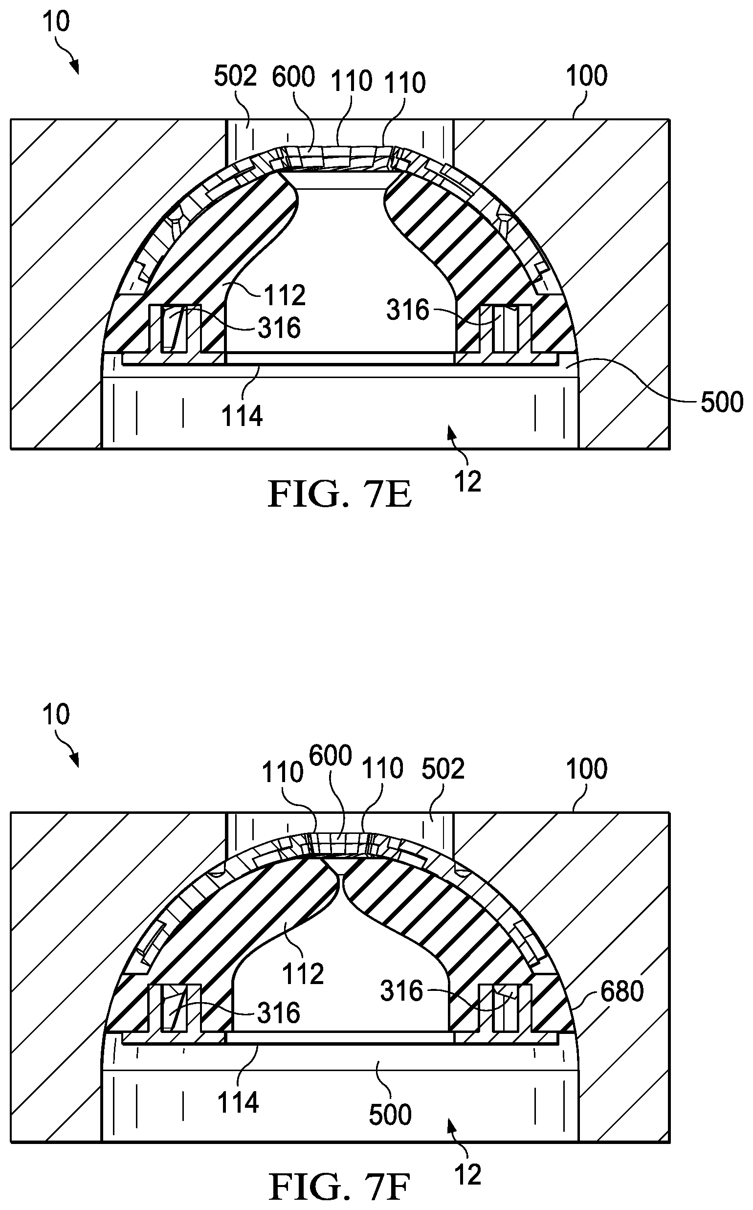
[0050] FIGS. 7A-7F show the operation of reducing the bore through the annular BOP 10 in accordance with an embodiment of the present disclosure. FIGS. 7A-7F correspond generally to earlier FIGS. 6A-6F in terms of closing positions of the annular packing element 12. In FIGS. 7A-7F, however, the operation is shown with the elastomer 112 of the packing element 12.
[0051] The elastomer 112 generally forms a bulk portion of the packing element 12. The elastomer 112 is a single piece of material coupled between the lower surfaces of each of the hardened segments 110 and above described surfaces of the lower plate 114. The elastomer 112 may be located both along the bore of the packing element 12 under the hardened segments 110 as well as in annular spaces 680 between the lower plate 114, the hardened segments 110, and the BOP head 100. The hardened segments 110 may be bonded directly to an upper surface of the elastomer 112, and the hardened segments 110 together may cover an entire upper surface of the elastomer 112 so that none of the elastomer 112 is exposed in spaces between the adjacent hardened segments 110. That way, no elastomer 112 will become extruded between adjacent hardened segments 110 during closing of the bore 600 through the annular packing element 12.
[0052] The elastomer 112 may be formed into the specific shape for the packing element 12 via a molding process. The elastomer 112 may be made from rubber or any other desirable elastomeric material that is sufficiently compressible for use in the disclosed packing/sealing operation.
[0053] The elastomer 112 is designed as having a free bore arrangement. That is, there is no restriction from the elastomer 112 when the BOP 10 is in the fully open position, as shown in FIG. 7A. As shown in the figure, the elastomer 112 generally has a consistent bore 700 therethrough, which is approximately the same diameter as the bore 502 through the BOP head 100 and the corresponding bore through the lower plate 114. The elastomer 112 does not come up as high as the uppermost portions of the hardened segments 110, and therefore no elastomer is extruded between these hardened segments 110 as they shift and move during the closing operation.
[0054] Once the piston is activated, thereby moving the lower plate 114 upward and contacting the hardened segments 110 with the spherical feature 500 of the BOP head 100, this causes the segments 110 to start to rotate across the spherical feature 500 (FIG. 7B). As the segments 110 are designed to create a tangential contact with the bore 600, continued motion of the piston (and therefore the lower plate 114 and hardened segments 110) starts to close the bore 600 of the packing element 12, which quickly becomes the effective bore of the BOP 10 (FIG. 7C).
[0055] The elastomer 112 is bonded with the hardened segments 110; as the segments 110 move, the elastomer 112 is also drawn toward the closing (restricted) bore 600. In addition, the piston pushing on the lower plate 114 is reducing the physical volume between the lower plate 114 and the spherical feature 502 of the BOP head 100. This causes the elastomer 112 to deform into the reducing volume, resulting in distortion of the elastomer 112, as shown in FIGS. 7B-7F. As the hardened segments 110 draw to a close (zero position of FIG. 6G), the elastomer 112 will have sufficiently deformed to create a seal against the supported segments 110. This is illustrated in FIG. 7F, for example, where the elastomer 112 has reached a zero position bore with the final movement of the hardened segments 110 still to come.
[0056] As shown in FIGS. 7A-7F, the hardened segments 110 provide restriction to the bore 600 during the closing operation. The hardened segments do not themselves create an effective seal for the wellbore. With the addition of the elastomer 112, both to the bore side and to an outer profile 680 (between the lower plate 114, the hardened segments 110, and the spherical feature 502 of the BOP head 100) the disclosed packing element 12 will provide an effective fluid tight seal of the BOP 10 once it is closed. With the tangential operation of the hardened segments 110 and the deformation of the elastomer 112, the annulus around a tubular through the BOP 10 can be sealed, allowing total variable bore operation of the packing element 12.
[0057] While the disclosure may be susceptible to various modifications and alternative forms, specific embodiments have been shown by way of example in the drawings and have been described in detail herein. However, it should be understood that the disclosure is not intended to be limited to the particular forms disclosed. Rather, the disclosure is to cover all modifications, equivalents, and alternatives falling within the spirit and scope of the disclosure as defined by the following appended claims.
* * * * *
D00000
D00001
D00002
D00003
D00004
D00005
D00006
D00007
D00008
D00009
D00010
D00011
D00012

D00013

D00014
XML
uspto.report is an independent third-party trademark research tool that is not affiliated, endorsed, or sponsored by the United States Patent and Trademark Office (USPTO) or any other governmental organization. The information provided by uspto.report is based on publicly available data at the time of writing and is intended for informational purposes only.
While we strive to provide accurate and up-to-date information, we do not guarantee the accuracy, completeness, reliability, or suitability of the information displayed on this site. The use of this site is at your own risk. Any reliance you place on such information is therefore strictly at your own risk.
All official trademark data, including owner information, should be verified by visiting the official USPTO website at www.uspto.gov. This site is not intended to replace professional legal advice and should not be used as a substitute for consulting with a legal professional who is knowledgeable about trademark law.