Support for a Folded Garment
WONG; John
U.S. patent application number 16/185368 was filed with the patent office on 2020-04-16 for support for a folded garment. This patent application is currently assigned to Taltech Limited. The applicant listed for this patent is Support for a Folded Garment. Invention is credited to John WONG.
| Application Number | 20200115147 16/185368 |
| Document ID | / |
| Family ID | 70159426 |
| Filed Date | 2020-04-16 |


| United States Patent Application | 20200115147 |
| Kind Code | A1 |
| WONG; John | April 16, 2020 |
Support for a Folded Garment
Abstract
A support for a folded garment, the support comprising a planar supporting member arranged to support the folded garment and a tab coupled to the planar supporting member. The tab is configured to project from a plane of the planar supporting member. The tab comprises an aperture and the aperture is configured to receive a button of the folded garment so as to hold the folded garment in a position against the planar supporting member.
| Inventors: | WONG; John; (Kowloon, HK) | ||||||||||
| Applicant: |
|
||||||||||
|---|---|---|---|---|---|---|---|---|---|---|---|
| Assignee: | Taltech Limited Tortola VG |
||||||||||
| Family ID: | 70159426 | ||||||||||
| Appl. No.: | 16/185368 | ||||||||||
| Filed: | November 9, 2018 |
| Current U.S. Class: | 1/1 |
| Current CPC Class: | B65D 85/182 20130101 |
| International Class: | B65D 85/18 20060101 B65D085/18 |
Foreign Application Data
| Date | Code | Application Number |
|---|---|---|
| Oct 12, 2018 | GB | 1816620.7 |
| Oct 22, 2018 | GB | 1817148.8 |
Claims
1. A support for a folded garment, the support comprising: a planar supporting member arranged to support the folded garment; a tab coupled to the planar supporting member, and configured to project from a plane of the planar supporting member; and wherein the tab comprises a slot, wherein the slot is configured to receive a thread of a button of the folded garment so as to hold the folded garment in a position against the planar supporting member, wherein the slot comprises projections forming a series of discrete holes in the slot which a thread of the button of the folded garment may be located.
2. A support according to claim 1 wherein the tab is integrally formed with the planar supporting member.
3. A support according to claim 1, wherein the planar supporting member comprises an orifice, and the tab is arranged to extend though said orifice in the planar supporting member.
4. A support according to claim 1, wherein the series of discrete holes are formed by projections which do not interdigitate.
5. A support according to claim 1, wherein the positions of the projections mirror one another so as to form the series of holes.
6. A support according to claim 1, wherein the projections are triangle shaped.
7. A support according to claim 1, wherein the projections are curved.
8. A support according claim 1, wherein the support further comprises an opening, wherein a portion of the slot terminates at the opening and where the opening has a width greater than the slot.
9. A support according to claim 8, wherein the opening is located at an end of the slot in the tab.
10. A support according to claim 1, wherein the tab comprises a foldable portion, the foldable portion arranged to fold out of a plane of the tab, and comprising a side of the slot.
11. A support according to claim 10, further comprising a second foldable portion opposing the said first foldable portion, the second foldable portion arranged to fold out of a plane of the tab and comprising a second side of the slot.
12. A support according to claim 1, wherein the planar support member comprises cardboard or plastic.
13. A support according to claim 1, wherein the tab comprises cardboard or plastic.
14. A support according to claim 1, further comprising a void, the void configured to provide a portion of the support in which no material of the support is present.
15. An article comprising a folded garment and a support according to claim 1, wherein the folded garment is folded over the planar supporting member such that a portion of the folded garment is located between the planar supporting member and the tab, and a button of the folded garment is received by the tab.
Description
TECHNICAL FIELD
[0001] The present invention relates to a support for a folded garment, and in particular, to a support for a folded shirt.
BACKGROUND
[0002] It is conventional practice in retailing to pack garments, such as shirts, in individual transparent bags and to fold the shirts so as to present an attractive appearance. During manufacturing, when a shirt has been produced, such as when it emerges from a pressing operation that follows sewing assembly, the shirt is folded in a specified manner and is usually provided with additional materials to stabilize the folded shape during packing, shipping, warehousing and distribution of the shirt.
[0003] One method of supporting the shirt is to use a cardboard insert, where the cardboard insert is usually in the form of an appropriately shaped flat sheet of cardboard, and is tucked inside a folded body of the shirt. For example, towards the end of a shirt manufacturing process, the cardboard insert may be placed at the back of the shirt, and then portions of the shirt, including the arm portions, may be folded back so as to fold over the cardboard insert, such that the cardboard insert can be said to be located inside the folded body of the shirt.
[0004] Further additional materials that can help support the shirt may include a plastic or cardboard insert to shape a neck of the shirt, a plastic or cardboard insert to maintain the shape of a collar of the shirt, and/or pins or clips to prevent slippage of one part of the shirt against another and/or hold the shirt relative to any of the other supporting materials, such as the cardboard insert. For example, one or more plastic clips may be used to secure the sleeves of the shirt to each other to prevent the sleeves from slipping relative to the rest of the folded shirt. One or more layers of a flexible material such as tissue paper may be placed between the shirt and a cardboard insert before the shirt is folded around the cardboard insert. The one or more layers of flexible material may improve the appearance of the folded shirt by, for example, at least partially occupying a volume between the cardboard insert and the shirt such that the shirt is pushed outwardly. FIG. 1 shows a portion of a folded shirt 1 according to a prior art method where clips 2 have been used to help support the shirt 1. The clips 2 effectively clamp the shirt 1 and the cardboard insert (not shown) together, thus preventing the shirt 1 from moving relative to the cardboard insert. This helps the shirt 1 maintain its folded shape during shipping and distribution.
[0005] Pins have been used to prevent slippage for decades but many users now specify "metal free" packaging, or otherwise prefer plastic clips because of perceived disadvantages of pins. For example, pins may injure customers if not removed before putting on the garment. Additionally, pins can damage the fabric of the garment if pushed through the yarn, for example. Pins can also become rusty after prolonged storage, and lubricants which may be applied to the pins to prevent rust can leave marks on the shirt. The marks may, for example, be especially visible on white shirts.
[0006] Furthermore, using pins, as well as plastic clips, for the aforementioned purpose adds additional time to the manufacture process, since, in many cases, a worker must manually add the pins or clips. The additional time increases with the number of pins or clips that must be used. Further still, using pins or clips adds an additional cost to the finished, packed shirt, both in terms of the additional time taken to package the shirt, and in terms of the cost of the individual pins and clips.
[0007] There remains a need to provide an improved method of supporting a folded garment, such as a shirt.
SUMMARY OF THE INVENTION
[0008] It is the objective of the invention to alleviate one or more of the aforementioned problems.
[0009] In a first aspect of the invention there is provided a support for a folded garment. The support comprises a planar supporting member arranged to support the folded garment, and a tab coupled to the planar supporting member, and configured to project from a plane of the planar supporting member. The tab comprises a slot, wherein the slot is configured to receive a thread of a button of the folded garment so as to hold the folded garment in a position against the planar supporting member. The slot further comprises projections forming a series of discrete holes in which a thread of the button of the folded garment may be located.
[0010] For example, the discrete holes may be formed between projections from one side of the slot meeting either of the other side of the slot, or projections of the other side of the slot. It will be appreciated that "meeting" does not necessarily mean touching. For example, while a number of discrete holes may be formed by the projections, there may be a relatively small space between the projections from one side and either of the other side of the slot, or projections of the other side of the slot. Therefore, the holes may be thought of as regions of the slot having a relatively large area of no material between each side of the slot, compared with regions of the slot where each side of the slot meet, providing a relatively small area of no material between each side of the slot.
[0011] Advantageously, the first aspect provides a support for a folded garment, such as a shirt, which does not require the use of pins or clips to hold the shirt in place relative to the support. This improves the packaging process by improving the speed with which shirts may be packaged and reducing the cost of the packaging process.
[0012] Providing a series of discrete holes provides a discrete space in which to locate the thread of the button when the button is pushed through the slot. The thread of the button is then constrained within the discrete hole. This is in contrast to, for example, slots having projections on either side of the slot which interdigitate, such as a zigzag line being cut to form the slot, where no discrete holes are provided. Providing discrete holes allows one hole to be selected for a given button, and provides an increase in space for the thread to be received and accomdated, while still constraining the thread to the discrete hole. This reduces deformation of the tab and reduces the risk of damage to the thread.
[0013] Optionally, the tab is integrally formed with the planar supporting member. The term "integrally formed" is intended to indicate that the tab and the planar supporting member are parts of a single body rather than the tab and the planar supporting member being two connected bodies. Alternatively, the planar supporting member comprises an orifice, and the tab is arranged to extend though said orifice in the planar supporting member. That is, the tab may be moved through the orifice to extend therefrom.
[0014] The tab may be held in place by any suitable means. For example, the tab may have an enlarged portion having a width greater than the width of the orifice so as to prevent the enlarged portion of the tab from extending through the orifice. Alternatively, an adhesive may be used to connect a portion of the tab to the planar supporting member.
[0015] The slot may be elongated, where the slot has a main axis (length) and a minor axis (width), where the size of the main axis is greater than the size of the minor axis. The main axis may, in use, run substantially parallel with an axis of the front buttons of a shirt. The word "slot" is not intended to limit the slot to having planar sides. The slot may have curved and/or angled sides, e.g, the projections of the slot may comprise teeth on one or more sides of the slot.
[0016] The series of discrete holes may be formed by projections which do not interdigitate For example, both sides of the slot may comprise projections and the position of the projections may mirror one another so as to form the series of holes.
[0017] The projections may be any suitable shape. For example, the projections may be triangle shaped, square shaped, curved etc. The projections may, for example, be teeth or wave-like structures. The projections may be formed integrally with the tab. The projections may be reinforced by, for example, increasing a thickness of the tab at the projections relative to the rest of the tab.
[0018] When the projections on both sides of the slot are triangle shaped, the discrete holes may be square, or may be diamond shaped.
[0019] The projections may be resiliently deformable.
[0020] Optionally, the aperture further comprises an opening, wherein a portion of the slot terminates at the opening and where the opening has a width greater than the slot. The opening may help facilitate moving the button into the slot by allowing the button to first pass through the opening. The opening may have a width greater than the width of the button. The opening may be located in either the tab, the planar support member, or may extend over both the tab and planar support member.
[0021] Optionally, the tab comprises a foldable portion, the foldable portion arranged to fold out of a plane of the tab, and comprising a first edge of the slot. The foldable portion may be formed by providing a slit in the tab substantially perpendicular to the slot.
[0022] A foldable portion which comprises a first edge of the slot allows the width of the slot to be increased as the foldable portion is folded out of the plane of the tab, facilitating moving a button through the slot.
[0023] Optionally, the tab comprises a second foldable portion opposing the first foldable portion, the second foldable portion arranged to fold out of a plane of the tab and comprising a second edge of the slot. The second foldable portion may be formed by providing a slit in the tab substantially perpendicular to the slot.
[0024] The first and second edges of the slot may be edges of the slot that run along the main axis of the slot.
[0025] Optionally, the planar support member comprises cardboard. The planar support member may comprise plastic.
[0026] Optionally, the tab comprises cardboard. The tab may comprise plastic.
[0027] The support may further comprise a void. The void may be configured to provide a portion of the support in which no material of the support is present. The void provides a region of the support in which a user can feel the folded garment without interference from the support.
[0028] In a second aspect of the invention there is provided an article. The article comprises a folded garment and a support according to the first aspect, wherein the folded garment is folded over the planar supporting member such that a portion of the folded garment comprising the button is located between the planar supporting member and the tab, and a button of the folded garment is received by the tab.
[0029] In a third aspect of the invention there is provided a support for a folded garment.
[0030] The support comprises a planar supporting member arranged to support the folded garment, and a tab coupled to the planar supporting member, and configured to project from a plane of the planar supporting member. The tab comprises an aperture, wherein the aperture is configured to receive a button of the folded garment so as to hold the folded garment in a position against the planar supporting member.
[0031] The aperture may comprise a slot. The slot may comprise projections.
[0032] Any of the features of any of the above aspects of the invention may be combined with any other feature of any of the other aspects of the invention, in any combination.
BRIEF DESCRIPTION OF DRAWINGS
[0033] Specific embodiments of the present invention will now be described, by way of example only, with reference to the accompanying drawings in which:
[0034] FIG. 1 shows a portion of a folded shirt according to a prior art method where clips have been used to help support the shirt;
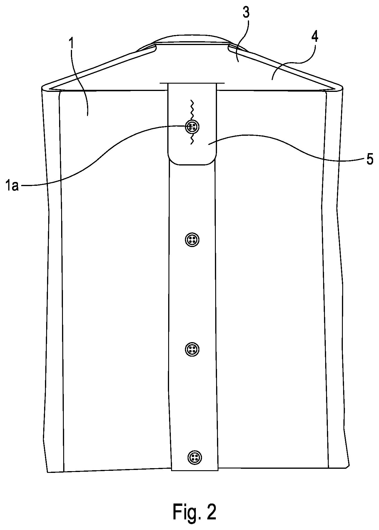
[0035] FIG. 2 shows a portion of a folded shirt according to a first embodiment of the invention;
[0036] FIG. 3 shows an enlarged view of a portion of FIG. 2;
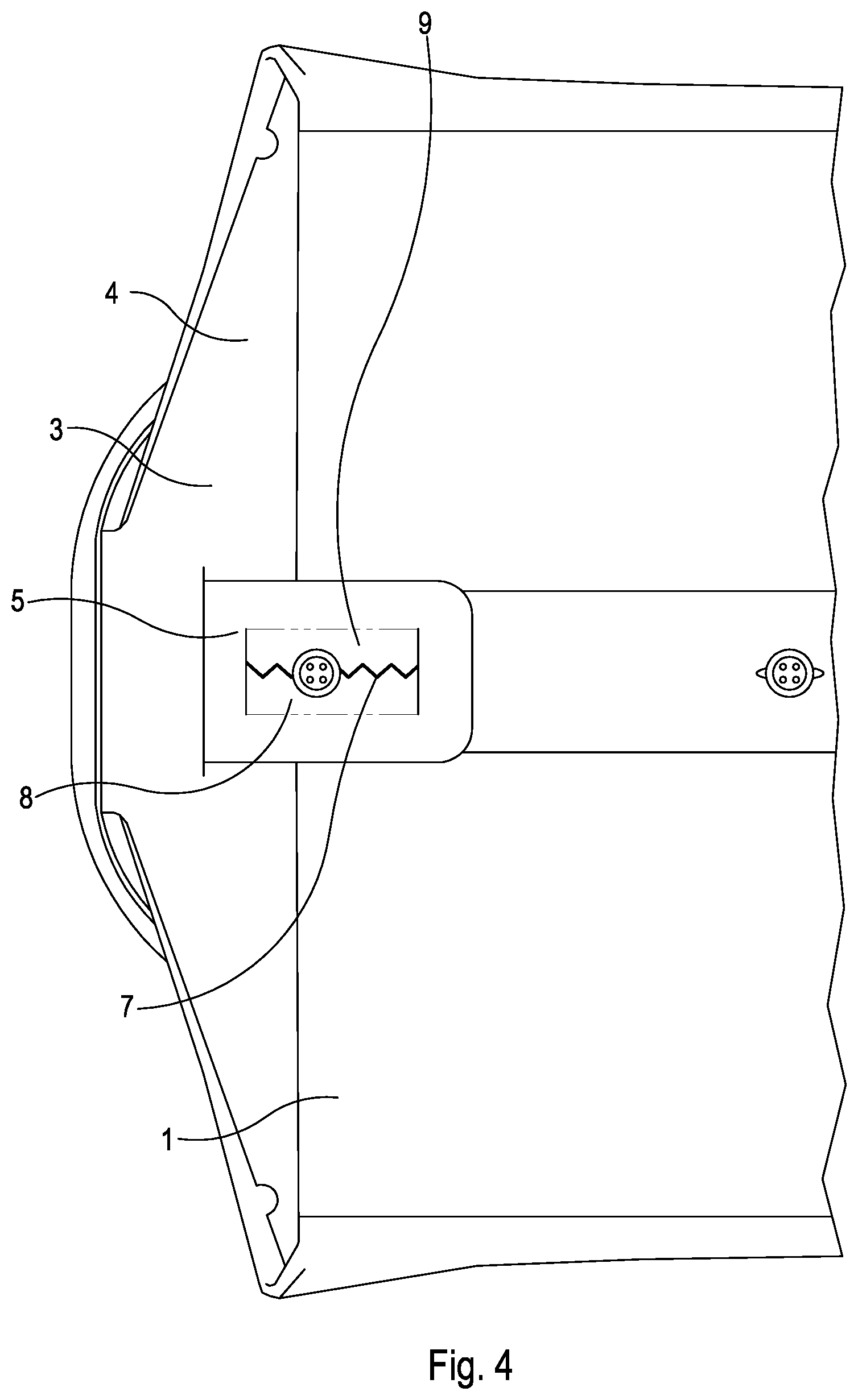
[0037] FIG. 4 shows a portion of a folded shirt according to a second embodiment of the invention;
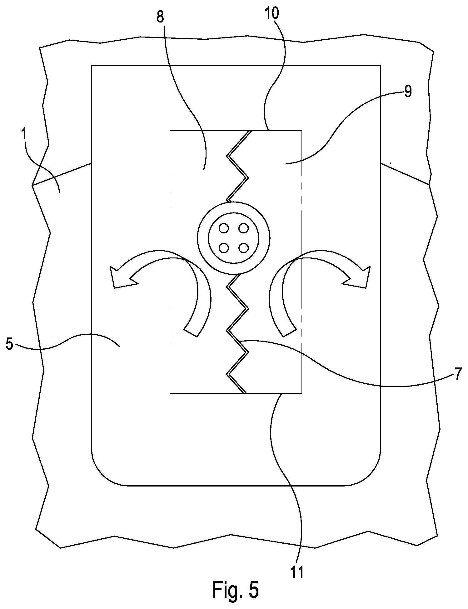
[0038] FIG. 5 shows an enlarged view of a portion of FIG. 4;
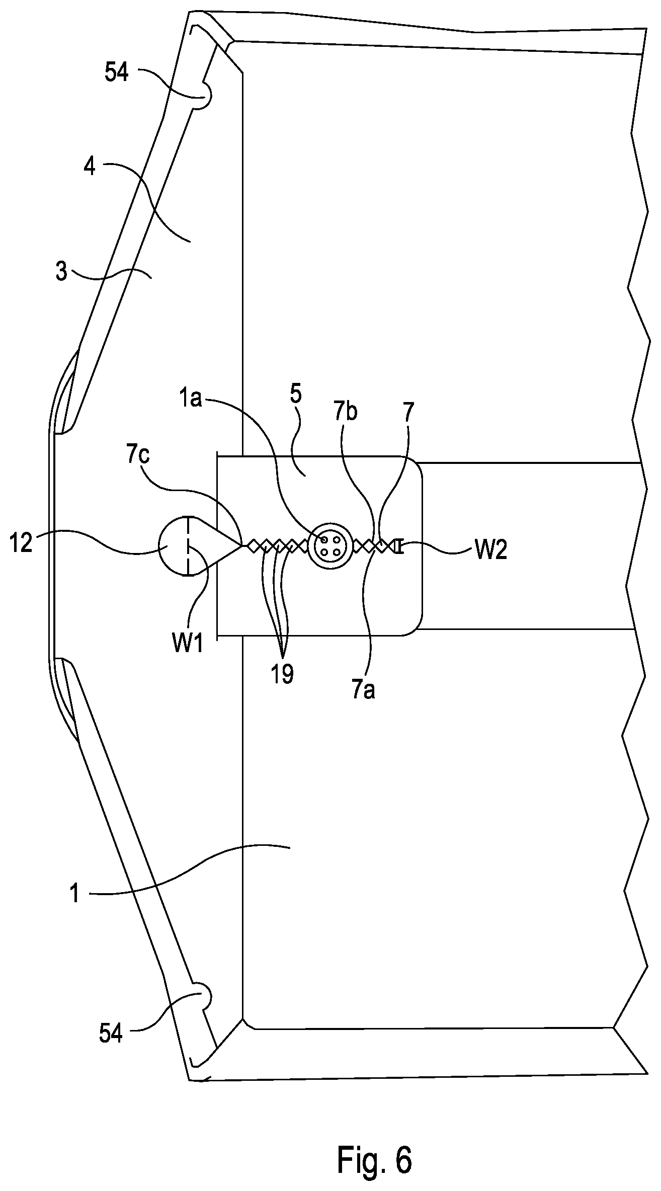
[0039] FIG. 6 shows a portion of a folded shirt according to a third embodiment of the invention;
[0040] FIG. 7 shows a portion of a folded shirt according to a fourth embodiment of the invention;
[0041] FIG. 8 shows a schematic view of a support according to a fifth embodiment of the invention;
[0042] FIG. 9 shows an illustration side view of a button located within a slot having interdigitate projections; and
[0043] FIG. 10 shows an illustration side view of a button located within a slot having non-interdigitate projections.
DETAILED DESCRIPTION
[0044] With reference to FIGS. 2 to 8, there will now be described several embodiments for a support for a folded garment, such as a shirt, which does not require the use of pins or clips. Common features between the embodiments use the same reference numerals.
[0045] FIG. 2 shows a portion of a folded shirt 1 and a support 3 according to a first embodiment of the invention, and. FIG. 3 shows an enlarged view of the support 3. The support 3 comprises a planar supporting member 4 and a tab 5 coupled to the planar supporting member 4. The planar supporting member 4 may, for example, be a sheet of cardboard. The planar supporting member 4 may be a sheet of, for example, plastic. The tab 5 may, for example, be a sheet of cardboard. The tab 5 may be a sheet of, for example, plastic.
[0046] In the first embodiment, the tab 5 is coupled to the planar supporting member 4 by extending though an orifice 6 in the planar supporting member 4. The planar supporting member 4 and the tab 5 may be separate components (i.e. not formed integrally), and the tab 5 is placed such that the tab 5 extends through the orifice 6. The tab 5 may have an enlarged portion (not shown) having a width greater than the width of the orifice 6 so as to prevent the enlarged portion of the tab 5 from extending through the orifice 6, and thus preventing the tab 5 from further extending from (and falling out of) the orifice 6.
[0047] The tab 5 is arranged to project from a plane of the planar supporting member 4. Such projection allows a portion of the shirt 1 to be placed between the planar supporting member 4 and the tab 5. The tab 5 may be able to pivot and/or flex relative to the planar supporting member 4. For example, the tab 5 may pivot about an axis coaxial with the orifice 6. The material of the tab 5 may also be resiliently deformable such that the tab 5 may flex.
[0048] The tab 5 comprises a slot 7. In the embodiment shown in FIGS. 2 and 3, the slot 7 is in the form of a zig-zag. The zig-zag shape may be formed by cutting the slot 7 in the tab 5 such that the slot 7 resembles a series of projections having complimentary formations 7a, 7b. In an alternative embodiment, the projections 7a, 7b need not have complimentary formations, i.e., the projections 7a, 7b may partially interdigitate, or may not interdigitate at all (see FIGS. 6 and 8 for example, which shows projections 7a, 7b which do not interdigitate). When the projections 7a, 7b do not interdigitate, tips of the projections 7a, 7b may touch each other.
[0049] The slot 7 is configured to receive a button 1a of the shirt 1. That is, the button 1a may be passed through the slot 7. The button 1a is connected to fabric of the shirt 1 in a conventional way, such as by using a thread 53 (shown in FIG. 9). As such, when the button 1a has passed through the slot 7, the thread 53 extends from the shirt 1, through the slot 7, to the button 1a. The button 1a may, for example, be a front button 1a of the shirt 1. As can be seen in FIG. 2, the shirt 1 is folded in such a way that a portion of the shirt 1 is located between the planar supporting member 4 and the tab 5. The portion of the shirt 1 located between the planar supporting member 4 and the tab 5 comprises the button 1a, where the button 1a faces towards the tab 5.
[0050] Once the shirt 1 is appropriately folded, the button 1a is moved through the slot 7. When the button 1a is in its normal position, i.e., when a plane of the button 1a generally coincides with a plane of the shirt 1, the width of the slot 7 is less than the width of the button 1a, which prevents the button 1a from passing back through the slot 7. In order to initially move the button 1a through the slot 7, a user may manipulate the button 1a, such as by rotating the button 1a so as to present a smaller width to the slot 7 (i.e. the button 1a is presented to the slot 7 side-on). Once the button 1a has been moved through the slot 7, the button 1a can return to its normal position, i.e. in the plane of the shirt 1. The button 1a is then located on an opposite side of the tab 5 to the portion of the shirt 1 to which the button 1a is coupled to.
[0051] The projections 7a, 7b may be resiliently deformable so as to assist with moving the button 1a through the slot 5. The projections 7a, 7b help constrain, grip and/or restrict movement of the thread 53 which connects the button 1a to the shirt 1, so as to hold the button 1a. In place relative to the tab 5. This in turn holds the shirt 1 in place relative to the planar supporting member 4. The shirt 1 is then ready for packing, where, for example, the folded shirt 1 is placed in a transparent plastic bag.
[0052] FIG. 4 shows a portion of a folded shirt 1 and a support 3 according to a second embodiment of the invention. FIG. 5 shows an enlarged view of the tab 5 of the support 3 shown in FIG. 4. The tab 5 comprises a first foldable portion 8 and a second foldable portion 9. The first and second foldable portions 8, 9 are formed by providing two slits 10, 11 at either end of the slot 7, such that the first and second foldable portions 8, 9 can fold out of a plane of the tab 5. The arrows in FIG. 5 show the direction in which the first and second foldable portions 8, 9 may fold.
[0053] The first and second foldable portions 8, 9, aid with passing the button 1a through the slot 7, because the first and second foldable portions 8, 9 allow the slot 7 to be opened up, i.e. the width of the slot 7 is increased, in order to assist with passing the button 1a through the slot 7. Once the button 1a has passed through the slot 7, the first and second foldable portions 8, 9 can be manipulated so as to return to their normal unfolded position, with the button 1a remaining on an opposite side of the tab 5 than the portion of the shirt 1 to which the button 1a is coupled. Furthermore, the button 1a then prevents the first and second foldable portions 8, 9 from folding back out of a plane of the tab 5 without intentional manipulation, such as when a user removes the tab 5, to avoid accidental removal of the button 1a from the tab 5.
[0054] FIG. 6 shows a portion of a folded shirt 1 and a support 3 according to a third embodiment of the invention. In the third embodiment, the tab 5 is integrally formed with the planar supporting member 4. In an embodiment, the integrally formed tab 5 is formed by cutting a portion of the planar support member 4 so as to define the tab 5 and then pivoting the tab 5 out of a plane of the planar support member 4. The support 3 is shown with two recesses 54 which may be used to each receive a clip for holding the shirt 1 to the support 3 While embodiments of the present invention relate to supports which can be used without pins or clips, providing a recess for receiving a clip provides additional flexibility to the support 3, allowing a user to choose whether to use a clip or not. It will be appreciated that such a feature is not essential.
[0055] The support 3 further comprises an opening 12 which is located at an end 7c of the slot 7 in the tab 5. The opening 12 is arranged such that it has a greater width W1 than a width W2 of the slot 7. The width W1 of the opening 12 may, for example, be about 1 cm. In the embodiment shown in FIG. 6, the opening 12 tapers in width towards the slot 7 (i.e. the opening 12 becomes narrower as the opening 12 approaches the slot 7). While the opening 12 is shown as being located substantially in the planar support member 4, it will be appreciated that the opening 12 may be located in the tab 5 (as shown in FIG. 7).
[0056] The opening 12 provides an enlarged portion of the slot 7 through which the button 1a can be more easily moved. For example, the width WI of the opening 12 may be greater than the diameter of the button 1a. Once the button 1a has been moved through the opening 12, the button 1a may be moved along the main axis of the slot 7 to a position where the slot 7 is sufficiently narrow to hold the button 1a in place, and which holds the shirt 1 in a suitable folded configuration. For example, as shown in FIG. 6, the button 1a has been moved downward (as viewed in FIG. 6) relative to the opening 12 such that the button 1a is located between the projections 7a, 7b. In the embodiment shown in FIG. 6, the projections 7a, 7b are triangular shaped and the positions of the projections 7a, 7b mirror one another so as to form a series of square holes 19 (that is, the projections 7a, 7b are not interdigitate). The series of square holes 19 are configured to provide discrete selection of positions in which to locate the button 1a, i.e. the thread 53 (see FIG. 10) which couples the button 1a to the shirt 1 is located in one of the square holes 19 when the button 1a has passed through the slot 7. In other words, the projections 7a, 7b form a series of discrete holes 19 in which the thread 53 of the button 1a of the shirt 1 may be located. The holes 19 formed by the projections 7a, 7b may take any shape, e.g. triangular, rectangular, diamond, etc., dependent on the shape of the projections 7a, 7b.
[0057] It will be appreciated that the opening 12 is not necessary in all embodiments. In other embodiments the opening 12 may be formed at the opposite end of the slot 7. In further embodiments, there may be two openings, one at either end of the slot 7.
[0058] Providing the slot with a series of projections 7a, 7b which do not interdigitate, such as that shown in FIG. 6, has advantages over projections 7a, 7b which interdigitate (such as that shown in FIG. 5). For example, use, and in particular, repeated use, of a slot 7 with projections 7a, 7b which interdigitate can cause the projections 7a, 7b to become deformed. For example, a slot 7 which is formed in a tab 5 by cutting a zigzag such that the formed projections 7a, 7b interdigitate leaves little distance between each projection 7a, 7b, as can be seen in FIG. 5. If the distance between the projections 7a, 7b is smaller than the width of the thread 53 passing between the projections 7a, 7b, the projections 7a, 7b will be pushed apart and deform. Said deformation may also cause the tab 5 to deform, such as becoming concave or convex.
[0059] Deformation of the tab 5 may lead to an increase in packing space, undesirable appearance, and compromise the structural integrity of the support 3. Additionally, deformation of either the projections 7a, 7b or the tab 5 will reduce the effectiveness of the connection between the shirt 1 and the support 3. For example, deformed projections 7a, 7b will not robustly hold the button 1a. Projections 7a, 7b which do not interdigitate do not suffer from the same drawbacks. This is because a larger distance is provided between the projections 7a, 7b in which the thread 53 of the button 1a may be located. For example, the square holes 19 shown in FIG. 6 provide adequate space for the thread 53 of the button la to be located without deforming the projections 7a, 7b of the tab 5.
[0060] A further advantage of projections 7a, 7b which do not interdigitate is a reduction in the risk of damage to the thread 53 of the button 1a. As described above, projections 7a, 7b which interdigitate leave little distance between each projection 7a, 7b along the length of the slot 7. This can cause the thread 53 to be constrained more tightly in its movement between each projection 7a, 7b. If the fit between the thread 53 and the projections 7a, 7b is too tight, excessive rubbing between the projections 7a, 7b and the thread 53 may occur, causing damage to the thread 53.
[0061] FIGS. 9 and 10 are illustrations of a side view of the thread 53 being located between projections 7a, 7b which interdigitate and which do not interdigitate respectively. As can be seen when comparing FIGS. 9 and 10, the additional space provided by the square hole 19 formed by projections 7a, 7b (which do not interdigitate) means that the projections 7a, 7b do not restrict movement of the thread 53 as strongly as in the case where the projections 7a, 7b interdigitate as shown in FIG. 9. Therefore, the arrangement shown in FIG. 10 reduces excessive rubbing between the thread 53 and projections 7a, 7b. This reduces the risk of causing damage to the thread 53, while maintaining the thread 53 within the confines of the square hole 19.
[0062] FIG. 7 shows a portion of a folded shirt 1 and a support 3 according to a fourth embodiment of the invention. As in the third embodiment, the tab 5 is integrally formed with the planar supporting member 4. The third embodiment or the fourth embodiment of the invention may be the preferred embodiment of the invention because the third and fourth embodiments comprise a tab 5 that is integrally formed with the planar supporting member 4. The fourth embodiment may be the preferred embodiment of the invention because the fourth embodiment also includes slits 21, 22 that assist in facilitating opening of the slot 7 thus allowing the button 1a to pass through the slot 7. The opening 12 of the fourth embodiment does not taper towards the slot 7, as in the third embodiment. That is, a side 12a of the opening 12 that meets with the end 7c of the slot 7 may be substantially perpendicular to the slot 7. The side 12a of the opening 12 that meets the end 7c of the slot may be generally transverse to the slot 7. The width W3 of the opening 12 is greater than the width W2 of the opening 12 of the third embodiment. The width W3 of the opening 12 may, for example, be in the range of about 1 cm to about 3 cm, e.g. about 1.7 cm. This arrangement helps to facilitate opening of the slot 7 in order to move the button 1a through the slot 7. For example, by providing a side 12a of the opening 12 that is relatively flat in the horizontal plane (as viewed in FIG. 7), portions of the tab 5 either side of the slot 7 may be bent more easily out of the plane of the tab 5, thus increasing the width W2 of the slot 7 and allowing the button 1a to pass through the slot 7.
[0063] In the example of FIG. 7, the tab 5 comprises two slits 21, 22 at an end of the slot 7 that opposes the opening 12. The slits 21, 22 are arranged such that they are generally transverse to the slot 7. That is, the slits 21, 22 extend in a direction that is not parallel with the slot 7. The slits 21, 22 are configured to assist in allowing the button 1a to pass through the slot 7 at an end of the slot 7 that opposes the opening 12 by increasing the extent to which the foldable portions 8, 9 are able to fold out of a plane of the tab 5. The slits 21, 22 allow the foldable portions 8, 9 to move with less restriction from the tab 5, thereby increasing the size and/or changing the shape of the slot 7 when the foldable portions 8, 9 are moved out of a plane of the tab 5. A distance 25 between an end of the slot 7 that opposes the opening 12 and an end of the tab 5 may be selected so as to decrease a risk of the tab 5 tearing when inserting or removing the button 1a from the slot 7. The distance 25 may, for example be in the range of about 0.5 cm to about 1 cm.
[0064] FIG. 8 shows a schematic view of a support 3 according to a fifth embodiment of the invention. FIG. 8 shows the support 3 in an unfolded configuration, showing values of relative measurements of features of the support 3. A first width 40 of the tab 5 at an end of the tab 5 that is attached to the planar support member 4 may, for example, be within the range of about 4.5 cm to about 6.5 cm. A second width 46 of the tab 5 at an end of the tab 5 that opposes the first width 40 may, for example, be in the range of about 3.5 cm to about 4.5 cm. A length 50 of the tab 5 may, for example, be in the range of about 5.5 cm to about 7.5 cm. The opening 12 may, for example, have a width 41 in the range of about 1.5 cm to about 2.0 cm. The opening 12 may, for example, have a length 42 in the range of about 0.5 cm to about 1 cm. The slot 7 may, for example, have a length 51 in the range of about 4.5 cm to about 5.5 cm.
[0065] In the example of FIG. 8 the tab 5 comprises a second opening 30 at an end of the slot 7 that opposes the opening 12. The second opening 30 performs a function similar to the slits 21, 22 shown in FIG. 7. That is, the second opening 30 assists in allowing a button to pass through the slot 7 at an end of the slot 7 that opposes the opening 12 by increasing the extent to which the foldable portions are able to fold out of a plane of the tab 5. The second opening 30 allows the foldable portions to move with less restriction from the tab 5, thereby increasing the size and/or changing the shape of the slot 7 when the foldable portions are moved out of a plane of the tab 5. The second opening 30 may, for example, have a width 45 in the range of about 0.5 cm to about 1 cm. The second opening 30 may, for example, have a length 48 in the range of about 0.5 cm to about 1 cm. A length 49 between the opening 12 and the second opening 30 may, for example, be in the range of about 5 cm to about 7 cm. It will be appricated that the second opening 30 may be replaced with a slit, or slits, such as that shown in FIG. 7,
[0066] In the example of FIG. 8, the width of the slot 7 increases from the opening 12 to the second opening 30. The size of the holes 19 may, for example, have a width that increases from about 0.3 cm to about 0.6 cm from the opening 12 to the second opening 30. That is, the width 43 of the slot 7 near the opening 12 may be about 0.3 cm and the width 44 of the slot 7 near the second opening 30 may be about 0.6 cm. A slot 7 that increases in width towards the second opening 30 may advantageously increase the ease with which a button is inserted into and/or is removed from the slot 7 at a location near the second opening 30. Alternatively a straight slot 7 (i.e. a slot 7 that doesn't have a varied width) may be provided.
[0067] Referring to FIG. 8, the planar supporting member 4 has a collar support 13, first, second, third and fourth wings, 14, 15, 16, 17, and a central support 18. It will be appreciated that these features are not essential to the use, and operation, of the tab 5. The collar support 13 can be folded so as to support the collar of a folded shirt. The first, second, third and fourth wings, 14, 15, 16, 17 help maintain the shape of the folded shirt, by reinforcing the corners of the folded shirt. The central support 18 is shown in FIG. 8 as being narrower than the wings, which reduces the amount of material used in the support 3, reducing both the weight and cost of the support 3. The width 47 of the central support 18 may, for example, be in the range of about 5 cm to about 7 cm. An additional advantage of providing a central support 18 which is narrower than the wings 14, 15, 16, 17 is that a portion 52 of the support 3 is provided in which no material of the support 3 is present. That is, a void is provided in the support 3. This allows a user, such as a customer, to feel the shirt 1 prior to unpacking, without interference from the support 3. For example, a customer may feel the softness of the fabric of the shirt by feeling the shirt 1 in portion 52. The portion 52 of the support 3 in which no material of the support is present may be achieved in any suitable way. For example, rather than using wings 14, 15, 16, 17 and a narrow central support 18, any portion of the support 3 may be cut out to provide a void as described.
[0068] While the embodiments described have referred to using projections 7a, 7b to help constrain, grip or restrict movement of the thread 53 of the button 1a, other such means may be used. For example, the slot 7 may have a length that is small enough to prevent substantial movement of the button, i.e. the length of the slot may be comparable to the length of the button. The tab 5 may comprise a number of series of such slots, where the button 1a is placed through an appropriated slot in the series which lines up with the way the shirt 1 has been folded. The support 3 may, for example, be generally I-shaped, generally T-shaped or generally rectangular. In general, the support 3 may be any desired shape.
[0069] While the embodiments described have related to shirts, it will be appreciated that the support 3 may be used with other garments having one or more buttons, such as t-shirts, trousers, jumpers, etc. The support for a folded garment described and depicted herein advantageously does not require the use of pins or clips to hold the folded garment in place relative to the support. Wastage is reduced because clips and/or pins are not needed. Costs involved in manufacturing folded garments are reduced because fewer components (i.e. clips and/or pins) are needed. The speed with which garments may be packaged is increased because workers don't need to spend time attaching clips or pins to the support, thus improving the productivity of a packaging process.
[0070] It will be appreciated by the person of skill in the art that various modifications may be made to the above described embodiments without departing from the scope of the present invention. The person of skill in the art will also realise that where appropriate, suitable parts of any of the embodiments may be used with other embodiments. For example, the opening 12 of the fourth embodiment may be used in the tab 5 of the first embodiment.
* * * * *
D00000
D00001
D00002
D00003
D00004
D00005
D00006
D00007
D00008
D00009
XML
uspto.report is an independent third-party trademark research tool that is not affiliated, endorsed, or sponsored by the United States Patent and Trademark Office (USPTO) or any other governmental organization. The information provided by uspto.report is based on publicly available data at the time of writing and is intended for informational purposes only.
While we strive to provide accurate and up-to-date information, we do not guarantee the accuracy, completeness, reliability, or suitability of the information displayed on this site. The use of this site is at your own risk. Any reliance you place on such information is therefore strictly at your own risk.
All official trademark data, including owner information, should be verified by visiting the official USPTO website at www.uspto.gov. This site is not intended to replace professional legal advice and should not be used as a substitute for consulting with a legal professional who is knowledgeable about trademark law.