Patting Bag Structure
Wu; Yun Ju ; et al.
U.S. patent application number 16/596517 was filed with the patent office on 2020-04-16 for patting bag structure. The applicant listed for this patent is Chang Yang Material Co. LTD.. Invention is credited to Ming Hua Huang, Dong Jhou Lee, Lung Hsun Song, Lin Chun Sun, Yun Ju Wu.
| Application Number | 20200115113 16/596517 |
| Document ID | / |
| Family ID | 66591859 |
| Filed Date | 2020-04-16 |


| United States Patent Application | 20200115113 |
| Kind Code | A1 |
| Wu; Yun Ju ; et al. | April 16, 2020 |
PATTING BAG STRUCTURE
Abstract
A patting bag structure, which is furled when an external force is applied thereto, includes a bag body and at least one elastic furling element. The bag body includes an opening, a patting portion and a housing portion, wherein the patting portion is connected to the housing portion, and the opening is connected to the housing portion by the patting portion. The at least one elastic furling element is disposed on the patting portion of the bag body, wherein the at least one elastic furling element is furled when the external force is applied thereto, and the patting portion is furled together with the elastic furling element so as to disconnect the opening from the housing portion.
| Inventors: | Wu; Yun Ju; (Huatan Township, TW) ; Huang; Ming Hua; (Huatan Township, TW) ; Song; Lung Hsun; (Huatan Township, TW) ; Lee; Dong Jhou; (Huatan Township, TW) ; Sun; Lin Chun; (Huatan Township, TW) | ||||||||||
| Applicant: |
|
||||||||||
|---|---|---|---|---|---|---|---|---|---|---|---|
| Family ID: | 66591859 | ||||||||||
| Appl. No.: | 16/596517 | ||||||||||
| Filed: | October 8, 2019 |
| Current U.S. Class: | 1/1 |
| Current CPC Class: | A45C 3/00 20130101; B65D 33/30 20130101 |
| International Class: | B65D 33/30 20060101 B65D033/30 |
Foreign Application Data
| Date | Code | Application Number |
|---|---|---|
| Oct 11, 2018 | TW | 107213754 |
Claims
1. A patting bag structure capable of being furled when an external force is applied thereto, the patting bag structure comprising: a bag body comprising an opening, a patting portion, and a housing portion, wherein the patting portion is connected to the housing portion, and the opening is connected to the housing portion by the patting portion; and at least one elastic furling element disposed on the patting portion of the bag body, wherein the at least one elastic furling element is furled when the external force is applied thereto, and the patting portion is furled together with the at least one elastic furling element so as to disconnect the opening from the housing portion.
2. The patting bag structure of claim 1, wherein the opening comprises an opening direction, the at least one elastic furling element has a long-strip shape and comprises a longitudinal axis, and the opening direction is parallel to the longitudinal axis.
3. The patting bag structure of claim 2, wherein the patting bag structure is furled and connected to a work element, and the patting bag structure is abutted against and positioned on the work element elastically by the at least one elastic furling element.
4. The patting bag structure of claim 1, wherein the bag body further comprises: a first bag portion, wherein the at least one elastic furling element is disposed on the first bag portion; a second bag portion corresponding to the first bag portion; a first side-bag portion connected between the first bag portion and the second bag portion, wherein the first side-bag portion is furled along with the first bag portion; a second side-bag portion connected between the first bag portion and the second bag portion, wherein the second side-bag portion is furled along with the first bag portion; and a bag bottom portion connected to the first bag portion, the second bag portion, the first side-bag portion and the second side-bag portion.
5. The patting bag structure of claim 4, further comprising: an engaging set disposed on the patting portion and adjacent to the opening, wherein the engaging set comprises: a first engaging element disposed on the first bag portion; and a second engaging element disposed on the second bag portion and corresponding to the first engaging element, wherein the second engaging element is detachably connected to the first engaging element so as to partially close the opening.
6. The patting bag structure of claim 1, wherein the at least one elastic furling element includes two or more elastic furling elements, and the elastic furling elements are arranged parallel to each other and spaced apart from each other.
7. The patting bag structure of claim 6, wherein the opening comprises an opening direction, each of the elastic furling elements has a long-strip shape and comprises a longitudinal axis, and the opening direction is parallel to the longitudinal axis.
8. The patting bag structure of claim 7, wherein the patting bag structure is furled and connected to a work element, and the patting bag structure is abutted against and positioned on the work element elastically by the elastic furling elements.
9. The patting bag structure of claim 6, wherein the bag body further comprises: a first bag portion, wherein the elastic furling elements are disposed on the first bag portion; a second bag portion corresponding to the first bag portion; a first side-bag portion connected between the first bag portion and the second bag portion, wherein the first side-bag portion is furled along with the first bag portion; a second side-bag portion connected between the first bag portion and the second bag portion, wherein the second side-bag portion is furled along with the first bag portion; and a bag bottom portion connected to the first bag portion, the second bag portion, the first side-bag portion and the second side-bag portion.
10. The patting bag structure of claim 9, further comprising: an engaging set disposed on the patting portion and adjacent to the opening, wherein the engaging set comprises: a first engaging element disposed on the first bag portion; and a second engaging element disposed on the second bag portion and corresponding to the first engaging element, wherein the second engaging element is detachably connected to the first engaging element so as to partially close the opening.
11. A patting bag structure capable of being furled when an external force is applied thereto, the patting bag structure comprising: a bag body comprising an opening, a patting portion, and a housing portion, wherein the patting portion is connected to the housing portion, and the opening is connected to the housing portion by the patting portion; at least one elastic furling element comprising a patting section and a housing section, wherein the patting section is connected to the housing section, the patting section and the housing section are disposed on the patting portion and the housing portion, respectively, the patting section is furled when the external force is applied thereto, and the patting portion is furled together with the patting section so as to disconnect the opening from the housing portion.
12. The patting bag structure of claim 11, wherein the opening comprises an opening direction, the at least one elastic furling element has a long-strip shape and comprises a longitudinal axis, and the opening direction is parallel to the longitudinal axis.
13. The patting bag structure of claim 12, wherein the patting bag structure is furled and connected to a work element, and the patting bag structure is abutted against and positioned on the work element elastically by at least one the elastic furling element.
14. The patting bag structure of claim 11, wherein the bag body further comprises: a first bag portion, wherein the at least one elastic furling element is disposed on the first bag portion; a second bag portion corresponding to the first bag portion; a first side-bag portion connected between the first bag portion and the second bag portion, wherein the first side-bag portion is furled along with the first bag portion; a second side-bag portion connected between the first bag portion and the second bag portion, wherein the second side-bag portion is furled along with the first bag portion; and a bag bottom portion connected to the first bag portion, the second bag portion, the first side-bag portion and the second side-bag portion.
15. The patting bag structure of claim 14, further comprising: an engaging set disposed on the patting portion and adjacent to the opening, wherein the engaging set comprises: a first engaging element disposed on the first bag portion; and a second engaging element disposed on the second bag portion and corresponding to the first engaging element, wherein the second engaging element is detachably connected to the first engaging element so as to partially close the opening.
16. A patting bag structure capable of being furled when an external force is applied thereto, and the patting bag structure comprising: a bag body comprising an opening, a patting portion, and a housing portion, wherein the patting portion is connected to the housing portion; and at least one elastic furling element disposed on the patting portion of the bag body, wherein the at least one elastic furling element is furled when the external force is applied thereto, and the patting portion is furled together with the at least one elastic furling element so as to form a furling space, and the housing portion is located in the furling space.
Description
RELATED APPLICATIONS
[0001] This application claims priority to Taiwan Application Serial Number 107213754, filed Oct. 11, 2018, which is herein incorporated by reference in its entirety.
BACKGROUND
Technical Field
[0002] The present disclosure relates to a bag structure. More particularly, the present disclosure relates to a patting bag structure.
Description of Related Art
[0003] In the recent society, the use of bags is very popular. The bags are widely used in supermarkets, vegetable markets, restaurants, and cold drink shops, etc., and have become indispensable in daily life.
[0004] The conventional bags have structures that can be classified into two types. One is bag structures having a hand-held portion and a bag body, and the other is bag structures having only a bag body. Although both of the aforementioned types of bag structures can be used to accommodate articles, other devices are needed so as to help the loading thereof. Thus, the convenience of the aforementioned bag is not insufficient. For example, a basket is needed so as to position the bag structure when a user is riding a bicycle. The transportation of the bag structure will become very difficult when the user is riding on a bike without a basket, especially to a bag structure without a hand-held portion. Furthermore, the opening of the conventional bag structure usually cannot be closed completely, so that the articles accommodated therein is easy to fall or leak out so as to cause inconvenience and dangerous situations to users.
SUMMARY
[0005] According to one aspect of the present disclosure, a patting bag structure capable of being furled when an external force is applied thereto, includes a bag body and at least one elastic furling element. The bag body includes an opening, a patting portion and a housing portion. The patting portion is connected to the housing portion, and the opening is connected to the housing portion by the patting portion. The at least one elastic furling element is disposed on the patting portion of the bag body, wherein the at least one elastic furling element is furled when the external force is applied thereto, and the patting portion is furled together with the elastic furling element so as to disconnect the opening from the housing portion.
[0006] According to another aspect of the present disclosure, a patting bag structure capable of being furled when an external force is applied thereto, includes a bag body and at least one elastic furling element. The bag body includes an opening, a patting portion and a housing portion, wherein the patting portion is connected to the housing portion, and the opening is connected to the housing portion by the patting portion. The at least one elastic furling element includes a patting section and a housing section, wherein the patting section is connected to the housing section, the patting section and the housing section are disposed on the patting portion and the housing portion, respectively, the patting section is furled when the external force is applied thereto, and the patting portion is furled together with the patting section so as to disconnect the opening from the housing portion.
[0007] According to further another aspect of the present disclosure, a patting bag structure capable of being furled when an external force is applied thereto, includes a bag body and at least one elastic furling element. The bag body includes an opening, a patting portion and a housing portion, wherein the patting portion is connected to the housing portion. The at least one elastic furling element is disposed on the patting portion of the bag body, wherein the at least one elastic furling element is furled when the external force is applied thereto, and the patting portion is furled together with the at least one elastic furling element so as to form a furling space, and the housing portion is located in the furling space.
BRIEF DESCRIPTION OF THE DRAWINGS
[0008] The present disclosure can be more fully understood by reading the following detailed description of the embodiment, with reference made to the accompanying drawings as follows:
[0009] FIG. 1 is a perspective view of a patting bag structure according to one example embodiment of the present disclosure.
[0010] FIG. 2 is a perspective view of a patting bag structure according to one example embodiment of the present disclosure.
[0011] FIG. 3 is a perspective view of a patting bag structure according to one example embodiment of the present disclosure.
[0012] FIG. 4 is a perspective view of a patting bag structure according to one example embodiment of the present disclosure.
[0013] FIG. 5 is a schematic view of the furled patting bag structure of FIG. 3.
[0014] FIG. 6 is a schematic view of a patting bag structure connected to a first work element according to one example embodiment of the present disclosure.
[0015] FIG. 7 is a schematic view of a patting bag structure connected to a second work element according to one example embodiment of the present disclosure.
[0016] FIG. 8 is a schematic view of a patting bag structure connected to a third work element according to one example embodiment of the present disclosure.
[0017] FIG. 9 is a schematic view of a patting bag structure connected to a fourth work element according to one example embodiment of the present disclosure.
[0018] FIG. 10 is a schematic view of a patting bag structure connected to a fifth work element according to one example embodiment of the present disclosure.
[0019] FIG. 11 is a schematic view of a patting bag structure connected to a sixth work element according to one example embodiment of the present disclosure.
[0020] FIG. 12 is a schematic view of a patting bag structure connected to a seventh work element according to one example embodiment of the present disclosure.
[0021] FIG. 13 is a schematic view of a patting bag structure connected to an eighth work element according to one example embodiment of the present disclosure.
[0022] FIG. 14 is a schematic view of a patting bag structure connected to a ninth work element according to one example embodiment of the present disclosure.
[0023] FIG. 15 is a schematic view of a patting bag structure connected to a tenth work element according to one example embodiment of the present disclosure.
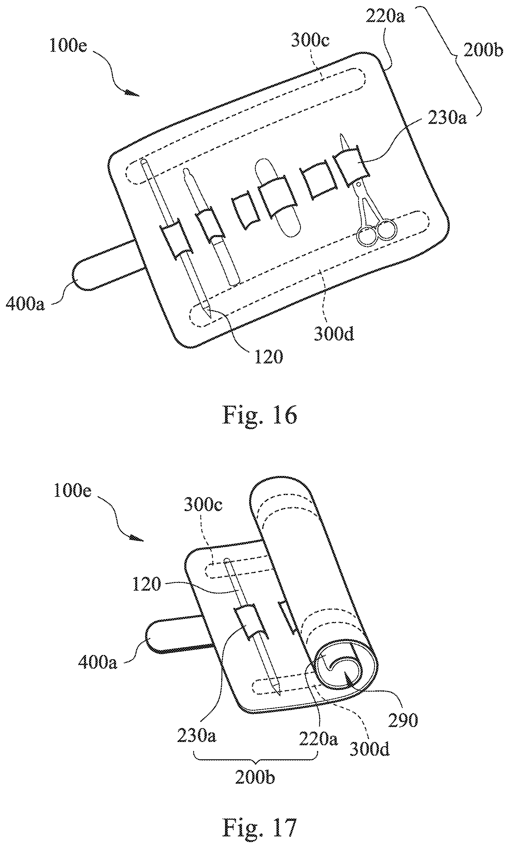
[0024] FIG. 16 is a schematic view of a patting bag structure according to one example embodiment of the present disclosure.
[0025] FIG. 17 is a schematic view of the patting bag structure of FIG. 16 in a furled state.
DETAILED DESCRIPTION
[0026] The present disclosure will be further exemplified by the following specific embodiments along drawings thereof so as to facilitate utilizing and practicing the present disclosure completely by the people skilled in the art without over-interpreting and over-experimenting. However, the readers should understand that the present disclosure should not be limited to these practical details thereof, that is, in some embodiments, these practical details are used to describe how to implement the materials and methods of the present disclosure and are not necessary. Furthermore, in order to simplify the drawings, some conventional structures and elements will be illustrated in a simple manner in the drawings, and the repeated elements may be represented by the same reference numerals.
[0027] Furthermore, in the present specification, when one element (or, structure and module) "is connected to", "is disposed on" or "is linked to" another element, it means the element can be directly connected to, disposed on or linked to another element or be indirectly connected to, disposed on or linked to another element (that is, there is an element disposed between the aforementioned element and another element). In other words, if an element is exactly illustrated as being "directly connected to", "directly disposed on" or "directly linked to" another element, there is without an element disposed between the aforementioned element and another element. Furthermore, the terms of "first", "second" and "third" are only for illustrating different elements or components and not used to limit the elements or components themselves. Thus, the first element/component can be named as the second element/component. Moreover, the combination of the elements/component/structures/modules described in the present specification are not well-known, conventional or common combination in the field, and it is hard for the person skilled in the arts to determine whether the combination relationship is obviousness or not based on the elements/components/structures/modules themselves are conventional or not.
[0028] Disclosed herein is a patting bag structure which is convenient for use, has a simple structure, and can be loaded without additional devices.
[0029] Please refer to FIG. 1 and FIG. 6 to FIG. 13. FIG. 1 is a schematic view of a patting bag structure 100 according to a first embodiment of the present disclosure. FIG. 6 is a schematic view of the patting bag structure 100 of FIG. 1 connected to a first work element 110a. FIG. 7 is a schematic view of the patting bag structure 100 of FIG. 1 connected to a second work element 110b. FIG. 8 is a schematic view of the patting bag structure 100 of FIG. 1 connected to a third work element 110c. FIG. 9 is a schematic view of the patting bag structure 100 of FIG. 1 connected to a fourth work element 110d. FIG. 10 is a schematic view of the patting bag structure 100 of FIG. 1 connected to a fifth work element 110e. FIG. 11 is a schematic view of the patting bag structure 100 of FIG. 1 connected to a sixth work element 110f. FIG. 12 is a schematic view of the patting bag structure 100 of FIG. 1 connected to a seventh work element 110g. FIG. 13 is a schematic view of the patting bag structure 100 of FIG. 1 connected to an eighth work element 110h. As shown in FIG. 1 and FIGS. 6 to 13, the patting bag structure 100 can be furled when an external force is applied thereto, and the patting bag structure 100 is furled and connected to a work element. The work element can be the first work element 110a, the second work element 110b, the third work element 110c, the fourth work element 110d, the fifth work element 110e, the sixth work element 110f, the seventh work element 110g or the eighth work element 110h. The patting bag structure 100 includes a bag body 200 and an elastic furling element 300.
[0030] The bag body 200 includes an opening 210, a patting portion 220 and a housing portion 230. The patting portion 220 is connected to the housing portion 230, and the opening 210 is connected to the housing portion 230 by the patting portion 220. In detail, the opening 210 includes an opening direction, and the bag body 200 further includes a first bag portion 240, a second bag portion 250, a first side-bag portion 260, a second side-bag portion 270 and a bag bottom portion 280, wherein the elastic furling element 300 is disposed on the first bag portion 240.
[0031] The opening direction of the opening 210 extends from the bag bottom portion 280 to the opening 210. In one embodiment, the elastic furling element 300 is disposed on the first bag portion 240 by an adhesive method or an engaging method. The second bag portion 250 corresponds to the first bag portion 240, and an area of the first bag portion 240 is equal to an area of the second bag portion 250. The first side-bag portion 260 is connected between the first bag portion 240 and the second bag portion 250, and the first side-bag portion 260 is furled along with the first bag portion 240. The second side-bag portion 270 is connected between the first bag portion 240 and the second bag portion 250, and the second side-bag portion 270 is furled along with the first bag portion 240. The bag bottom portion 280 is connected to the first bag portion 240, the second bag portion 250, the first side-bag portion 260 and the second side-bag portion 270. The bag body 200 can be made of a soft material such as silicone, polyurethane (TPU) or leather. Furthermore, a surface of the bag body 200 can be coated with a reflective material. Therefore, it is favorable for the bag body 200 to be identified and found at night or in the dark easily, so that the safety of a user can be increased.
[0032] The elastic furling element 300 is disposed on the patting portion 220 of the bag body 200. The elastic furling element 300 is furled when the external force is applied thereto, so that the patting portion 220 is furled together with the elastic furling element 300 so as to disconnect the opening 210 from the housing portion 230. In detail, the external force can be a flapping force. The elastic furling element 300 has a long-strip shape and includes a longitudinal axis, and the opening direction of the opening 210 is parallel to the longitudinal axis. The elastic furling element 300 can be made of a metal material, and in one embodiment, the metal material is manganese. Furthermore, the elastic furling element 300 being furled can be straightening by another external force so as to recover its original shape. Therefore, the use thereof is very convenient and rapid to the user.
[0033] The first work element 110a of FIG. 6 is a top tube of a bicycle. The second work element 110b of FIG. 7 is a horizontal tube of a baby carriage. The third work element 110c of FIG. 8 is a horizontal tube of a luggage. The fourth work element 110d of FIG. 9 is an armrest of a chair. The fifth work element 110e of FIG. 10 is a chair back of a chair. The sixth work element 110f of the FIG. 11 is a horizontal tube of a shopping cart. The seventh work element 110g of FIG. 12 is an arm, and the eighth work element 110h of FIG. 13 is a door. Each of the first work element 110a, the second work element 110b, the third work element 110c, the fourth work element 110d, the sixth work element 110f and the seventh work element 110g has a cylindrical strip shape, and an extending direction of each of the first work element 110a, the second work element 110b, the third work element 110c, the fourth work element 110d, the sixth work element 110f and the seventh work element 110g is perpendicular to the longitudinal axis of the elastic furling element 300. Therefore, the elastic furling element 300 of the patting bag structure 100 of the present disclosure can be furled by patting the opening 210 thereof after using for storage so as to seal the opening 210 quickly. Furthermore, the patting bag structure 100 of the present disclosure can be abutted against to and positioned on a wide variety of work elements elastically by the elastic furling element 300 of the furled portion thereof. Therefore, the patting bag structure 100 of the present disclosure not only has a simple structure but also is easy to use, so that it is favorable for resolving the conventional problems that the bag body should be equipped with an additional sealing structure and other devices are needed so as to help the loading of the bag body.
[0034] Please refer to FIG. 1, FIG. 2 and FIGS. 6 to 13. FIG. 2 is a schematic view of a patting bag structure 100a according to a second embodiment of the present disclosure. The patting bag structure 100a is furled when an external force is applied thereto, and the patting bag structure 100a is furled and connected to a work element. The patting bag structure 100a includes a bag body 200, an elastic furling element 300a and an elastic furling element 300b.
[0035] In the embodiment of FIG. 2, the structure of the bag body 200 is the same as that of the bag body 200 of FIG. 1, so that the detail thereof is not described thereto. In particular, the patting bag structure 100a according to the embodiment of FIG. 2 further includes two elastic furling elements 300a, 300b. Both of the elastic furling element 300a and the elastic furling element 300b are disposed on the patting portion 220 of the bag body 200, and the elastic furling element 300a and the elastic furling element 300b are arranged parallel to each other and spaced apart from each other. The elastic furling element 300a and the elastic furling element 300b are furled when the external force is applied thereto, and the patting portion 220 is furled together with the elastic furling element 300a and the elastic furling element 300b so as to disconnect the opening 210 from the housing portion 230. In other words, the elastic furling element 300a and the elastic furling element 300b are simultaneously furled when the external force is applied thereto, and the patting portion 220 of the bag body 200 is furled correspondingly so as to close the opening 210 adjacent to the patting portion 220 and then make the housing portion 230 to form a sealed space. Therefore, the elastic furling element 300a and the elastic furling element 300b of the patting bag structure 100a of the present disclosure can be furled by patting the opening 210 thereof after using for storage so as to seal the bag body 200 quickly. Furthermore, the patting bag structure 100a of the present disclosure can be abutted against to and positioned on a wide variety of work elements elastically by the elastic furling element 300a and the elastic furling element 300b of the furled portion thereof. Therefore, the patting bag structure of the present disclosure not only has a simple structure but also is easy to use, so that it is favorable for resolving the conventional problems that the bag body should be equipped with an additional sealing structure and other devices are needed so as to help the loading of the bag body.
[0036] Please refer to FIG. 2 to FIG. 13. FIG. 3 is a first schematic view of a patting bag structure 100b according to a third embodiment of the present disclosure. FIG. 4 is a second schematic view of a patting bag structure 100b according to the third embodiment of the present disclosure. FIG. 5 is a furling schematic view of the patting bag structure 100b of FIG. 3. As shown in FIG. 2 to FIG. 13, the patting bag structure 100b is furled when an external force is applied thereto. The patting bag structure 100b includes a bag body 200, an elastic furling element 300c, an elastic furling element 300d and an engaging set 400.
[0037] In the embodiment of FIG. 3, the structure of the bag body 200 is the same as that of the bag body 200 of FIG. 1, so that the detail thereof is not described thereto.
[0038] In particular, the patting bag structure 100b according to the embodiment of FIG. 3 further includes two elastic furling elements 300c, 300d and the engaging set 400. Each of the elastic furling elements 300c and 300d includes a patting section (reference number is omitted) and a housing section (reference number is omitted), wherein the patting section is connected to the housing section, and the patting section and the housing section are disposed on the patting portion 220 and the housing portion 230, respectively. The patting section is furled when the external force is applied thereto, and the patting portion 220 is furled together with the patting section so as to disconnect the opening 210 from the housing portion 230. In other words, the patting section of each of the elastic furling elements 300c and 300d is configured to be patted and the be furled correspondingly, and the housing section is configured to accommodate articles and support the shape thereof. Furthermore, the engaging set 400 is disposed on the patting portion 220 and adjacent to the opening 210. The engaging set 400 includes a first engaging element 410 and a second engaging element 420. The first engaging element 410 is disposed on the first bag portion 240. The second engaging element 420 is disposed on the second bag portion 250 and corresponds to the first engaging element 410. The second engaging element 420 is connected to the first engaging element 410 detachably so as to partially close the opening 210. Moreover, it is worth to be noted that the engaging set 400 also can be disposed on the bag body 200 of the patting bag structure 100 of FIG. 1 or on the bag body 200 of the patting bag structure 100a of FIG. 2 so as to partially close the opening 210 by the engaging set 400 and prevent the articles accommodated in the bag body 200 from falling or leaking out. Therefore, the patting section of the elastic furling element 300c and the elastic furling element 300d of the patting bag structure 100b of the present disclosure can be furled by patting the opening 210 thereof after using for storage so as to seal the opening 210 of the bag body 200 quickly. Furthermore, the patting bag structure 100b of the present disclosure can be abutted against to and positioned on a wide variety of work elements elastically by the elastic furling element 300c and the elastic furling element 300d of the furled portion thereof. Therefore, the patting bag structure of the present disclosure not only has a simple structure but also is easy to use, so that it is favorable for resolving the conventional problems that the bag body should be equipped with an additional sealing structure and other devices are needed so as to help the loading of the bag body.
[0039] Please refer to FIG. 2 and FIG. 14. FIG. 14 is a schematic view of a patting bag structure 100c connected to a ninth work element 110i. The patting bag structure 100c includes a bag body 200, two elastic furling elements (reference numbers are not shown) and a connecting element 500. In the illustrated embodiment, the structures of the bag body 200 and the two elastic furling elements are the same as those of the bag body 200, the elastic furling element 300a and the elastic furling element 300b of FIG. 2, respectively, so that the detail thereof is not described thereto. The connecting element 500 is connected to an outer portion of the bag body 200 and includes a hole (reference number is omitted), and the hole is configured to pass through a hook element of the work element 110i correspondingly. The connecting element 500 is disposed on the housing portion 230. When the bag body 200 is furled, the connecting element 500 is still exposed and located on the outer portion of the bag body 200 so as to pass through the hook element. Therefore, the elastic furling element of the patting bag structure 100c of the present disclosure can be furled by patting the opening (not shown) thereof after using for storage so as to seal the bag body 200 quickly, and the patting bag structure 100c of the present disclosure also has a simple structure and is easy to use. Furthermore, by the arrangement of the connecting element 500, the patting bag structure 100c of the present disclosure can be connected to a hook element or a tubular element with thin structure, so that the application range thereof can be further increased.
[0040] Please refer to FIG. 2 and FIG. 15. FIG. 15 is a schematic view of a patting bag structure 100d connected to a tenth work element 110j. The patting bag structure 100d includes a bag body 200a and two elastic furling elements (reference numbers are not shown). In the illustrated embodiment, the structures of the elastic furling elements are the same as those of the elastic furling element 300a and the elastic furling element 300b of FIG. 2, so that the detail thereof is not described thereto. Furthermore, the bag body 200a is similar to the bag body 200 of FIG. 2, and the only difference therebetween is that the bag body 200a does not include the second side-bag portion 270. In detail, as shown in FIG. 15, because the bag body 200a is without the second side-bag portion 270, the bag body 200a can have a housing hole and form as a housing box. As shown in FIG. 15, the tenth work element 110j is a straight bar, and three bag bodies 200a are furled and positioned on the straight bar. The vertical position and the horizontal position of the three bag bodies 200a, respectively, are different. Therefore, the elastic furling element of the patting bag structure 100d of the present disclosure can be furled by patting the opening (not shown) thereof after using for storage so as to seal the bag body 200a and position on the tenth work element 110j quickly, and the patting bag structure 100d of the present disclosure also has a simple structure and is easy to use. Furthermore, the vertical space can be more effectively used by the combination of a plurality of the patting bag structure 100d formed as a plurality of housing boxes and the tenth work element 110j.
[0041] FIG. 16 is a schematic view of a patting bag structure 100e according to a sixth embodiment of the present disclosure. FIG. 17 is a furling schematic view of the patting bag structure 100e of FIG. 16. As shown in FIGS. 16 and 17, the patting bag structure 100e is furled when an external force is applied thereto. The patting bag structure 100e includes a bag body 200b, an elastic furling element 300c, an elastic furling element 300d and an engaging set 400a.
[0042] The bag body 200b includes a patting portion 220a and a housing portion 230a, and the patting portion 220a is connected to the housing portion 230a. The elastic furling element 300c and the elastic furling element 300d are disposed on the patting portion 220a of the bag body 200b. The elastic furling element 300c and the elastic furling element 300d are furled when the external force is applied thereto, and the patting portion 220a is furled together with the elastic furling element 300c and the elastic furling element 300d so as to form a furling space 290, and the housing portion 230a is located in the furling space 290. Furthermore, a number of the housing portion 230a can be more than one. As shown in FIG. 16, when the patting portion 220a is arranged flat, each of the housing portions 230a can be used to accommodate one of the articles 120. For example, a pen can pass through a hole of the housing portion 230a so as to be positioned between the patting portion 220a and the housing portion 230a. Furthermore, the engaging set 400a can be a hook and loop fastener, a magnetic strip or a buckle. As shown in FIG. 17, when the patting portion 220a is furled, the patting bag structure 100e can be positioned and formed as a fixed cylindrical shape by the engaging set 400a so as to prevent the article 120 from falling due to the spreading out of the patting portion 220a. Therefore, the patting bag structure 100e of the present disclosure can be used to accommodate a variety of articles 120 in the furling space 290 by the patting portion 220a being furled. The patting bag structure 100e of the present disclosure not only has a simple structure and is convenient to use, but it is favorable for resolving the conventional problems that the bag body is needed to furl by hands.
[0043] According to the aforementioned embodiments, the patting bag structure of the present disclosure has advantages listed as follows. First, the elastic furling element of the patting bag structure can be furled by patting the opening thereof after using for storage so as to seal the bag body quickly, and the patting bag structure of the present disclosure can be furled and connected to a variety of work elements by the patting section being furled. The patting bag structure of the present disclosure not only has a simple structure and is easy to use, but it is favorable for resolving the conventional problems that the bag body should be equipped with an additional sealing structure and other devices are needed so as to help the loading of the bag body. Second, the opening of the patting bag structure of the present disclosure can be partially closed by the engaging set so as to prevent the articles accommodated in the bag body from falling or leaking out. Third, the elastic furling element being furled can be straightening by an external force so as to recover its original shape, and the use thereof is very convenient and rapid to the user. Fourth, the patting bag structure of the present disclosure can be connected to a hook element or a tubular element with thin structure, so that the application range thereof can be further increased. Fifth, the vertical space can be more effectively used by a plurality of the patting bag structure formed as a plurality of housing boxes. Sixth, the patting bag structure of the present disclosure can be used to accommodate a variety of articles in the furling space by the patting portion being furled. The patting bag structure of the present disclosure not only has a simple structure and is convenient to use, but it is favorable for resolving the conventional problems that the bag body is needed to furl by hands.
[0044] Although the present disclosure has been described in considerable detail with reference to certain embodiments thereof, other embodiments are possible. Therefore, the spirit and scope of the appended claims should not be limited to the description of the embodiments contained herein.
[0045] It will be apparent to those skilled in the art that various modifications and variations can be made to the structure of the present disclosure without departing from the scope or spirit of the disclosure. In view of the foregoing, it is intended that the present disclosure cover modifications and variations of this disclosure provided they fall within the scope of the following claims.
* * * * *
D00000
D00001
D00002
D00003
D00004
D00005
D00006
D00007
D00008
D00009
XML
uspto.report is an independent third-party trademark research tool that is not affiliated, endorsed, or sponsored by the United States Patent and Trademark Office (USPTO) or any other governmental organization. The information provided by uspto.report is based on publicly available data at the time of writing and is intended for informational purposes only.
While we strive to provide accurate and up-to-date information, we do not guarantee the accuracy, completeness, reliability, or suitability of the information displayed on this site. The use of this site is at your own risk. Any reliance you place on such information is therefore strictly at your own risk.
All official trademark data, including owner information, should be verified by visiting the official USPTO website at www.uspto.gov. This site is not intended to replace professional legal advice and should not be used as a substitute for consulting with a legal professional who is knowledgeable about trademark law.