Fuse And Contactor With Active Current Injection
Fisher; Brandon William
U.S. patent application number 16/710382 was filed with the patent office on 2020-04-16 for fuse and contactor with active current injection. The applicant listed for this patent is Eaton Intelligent Power Limited. Invention is credited to Brandon William Fisher.
| Application Number | 20200114776 16/710382 |
| Document ID | / |
| Family ID | 64267819 |
| Filed Date | 2020-04-16 |


View All Diagrams
| United States Patent Application | 20200114776 |
| Kind Code | A1 |
| Fisher; Brandon William | April 16, 2020 |
FUSE AND CONTACTOR WITH ACTIVE CURRENT INJECTION
Abstract
A system including a vehicle having a motive electrical power path, a power distribution unit comprising a current protection circuit disposed in the motive electrical power path, the current protection circuit comprising a thermal fuse and a contactor in a series arrangement with the thermal fuse. The system further including a current source circuit electrically coupled to the thermal fuse and structured to inject a current across the thermal fuse, a hardware filter electrically coupled to the thermal fuse, the hardware filter comprising a cutoff frequency determined in response to an injection frequency of the current source circuit, and sa voltage determination circuit electrically coupled to the thermal fuse and structured to determine an injected voltage amount in response to the filtered injected current.
| Inventors: | Fisher; Brandon William; (Portland, OR) | ||||||||||
| Applicant: |
|
||||||||||
|---|---|---|---|---|---|---|---|---|---|---|---|
| Family ID: | 64267819 | ||||||||||
| Appl. No.: | 16/710382 | ||||||||||
| Filed: | December 11, 2019 |
Related U.S. Patent Documents
| Application Number | Filing Date | Patent Number | ||
|---|---|---|---|---|
| 16184185 | Nov 8, 2018 | |||
| 16710382 | ||||
| 62583355 | Nov 8, 2017 | |||
| 62583367 | Nov 8, 2017 | |||
| 62583428 | Nov 8, 2017 | |||
| Current U.S. Class: | 1/1 |
| Current CPC Class: | H01M 2220/20 20130101; H01M 2/202 20130101; H02H 3/087 20130101; B60L 58/21 20190201; B60L 3/04 20130101; H01H 39/00 20130101; B60L 50/64 20190201; H01M 2/1083 20130101 |
| International Class: | B60L 58/21 20060101 B60L058/21; B60L 50/64 20060101 B60L050/64; H01M 2/20 20060101 H01M002/20; H01M 2/10 20060101 H01M002/10; B60L 3/04 20060101 B60L003/04; H02H 3/087 20060101 H02H003/087 |
Foreign Application Data
| Date | Code | Application Number |
|---|---|---|
| Nov 8, 2017 | IN | 201711039847 |
| Nov 8, 2017 | IN | 201711039848 |
| Nov 8, 2017 | IN | 201711039849 |
| Nov 8, 2017 | IN | 201711039850 |
Claims
1. A system, comprising: a vehicle having a motive electrical power path; a power distribution unit comprising a current protection circuit disposed in the motive electrical power path, the current protection circuit comprising a thermal fuse and a contactor in a series arrangement with the thermal fuse; a current source circuit electrically coupled to the thermal fuse and structured to inject a current across the thermal fuse; a hardware filter electrically coupled to the thermal fuse, the hardware filter comprising a cutoff frequency determined in response to an injection frequency of the current source circuit; and a voltage determination circuit electrically coupled to the thermal fuse and structured to determine an injected voltage amount in response to the filtered injected current.
2. A controller, comprising: a current protection circuit disposed in a motive electrical power path, the current protection circuit comprising a thermal fuse and a contactor in a series arrangement with the thermal fuse; a current source circuit electrically coupled to the thermal fuse and structured to inject a current across the thermal fuse; a hardware filter electrically coupled to the thermal fuse, the hardware filter comprising a cutoff frequency determined in response to an injection frequency of the current source circuit; and a voltage determination circuit electrically coupled to the thermal fuse and structured to determine an injected voltage amount in response to the filtered injected current.
3. A method, comprising: powering a motive electrical power path of a vehicle through a current protection circuit including a thermal fuse and a contactor in a series arrangement with the thermal fuse; injecting a current across the thermal fuse; determining a cutoff frequency for a filter in response to an injection frequency of the current; and filtering the injected current; and determine an injected voltage amount in response to the filtered injected current.
Description
CROSS REFERENCE TO RELATED APPLICATIONS
[0001] This application is a continuation of U.S. patent application Ser. No. 16/184,185, filed on Nov. 8, 2018, and entitled "POWER DISTRIBUTION UNIT AND FUSE MANAGEMENT FOR AN ELECTRIC MOBILE APPLICATION" (EATN-2300-U01).
[0002] U.S. patent application Ser. No. 16/184,185 claims priority to the following U.S. Provisional Patent Application Ser. Nos. 62/583,355, filed 8 Nov. 2017, and entitled "ACTIVE/PASSIVE THERMAL PROTECTION OF TEMPERATURE SENSITIVE COMPONENTS" (EATN-2001-P01); Ser. No. 62/583,367, filed 8 Nov. 2017, and entitled "FUSE AND CONTACTOR FOR CIRCUIT PROTECTION" (EATN-2002-P01); and Ser. No. 62/583,428, filed 8 Nov. 2017, and entitled "FUSE LIFE EXTENDER METHOD" (EATN-2006-P01).
[0003] U.S. patent application Ser. No. 16/184,185 also claims priority to the following Indian Provisional Patent Applications: Serial Number 201711039846, filed 8 Nov. 2017, and entitled "FUSE CURRENT MEASUREMENT WITH ACTIVE INJECTION SYSTEM" (EATN-2003-P01-IN); Serial Number 201711039847, filed 8 Nov. 2017, and entitled "NULL OFFSET DETECTION AND DIAGNOSTICS" (EATN-2004-P01-IN); Serial Number 201711039848, filed 8 Nov. 2017, and entitled "DIGITAL FILTERS TO MINIMIZE PHASE SHIFT AND INDUCED HARMONICS" (EATN-2005-P01-IN); Serial Number 201711039849, filed 8 Nov. 2017, and entitled "CALIBRATION OF FUSE CURRENT MEASUREMENTS" (EATN-2007-P01-IN); and Serial Number 201711039850, filed 8 Nov. 2017, and entitled "UNIQUE CURRENT INJECTION WAVEFORM TO IMPROVE INJECTION MEASUREMENT ACCURACY" (EATN-2008-P01-IN).
[0004] All of the above patent documents are incorporated herein by reference in their entirety.
FIELD
[0005] Without limitation to a particular field of technology, the present disclosure is directed to electrical power distribution, and more particularly to electronic power distribution for highly variable load applications.
BACKGROUND
[0006] Electrical power distribution in many applications is subject to a number of challenges. Applications having a highly variable load, such as mobile applications or vehicles, subject fuses in the power channels to rapid swings in power throughput and induce thermal and mechanical stresses on the fuses. Certain applications have a high cost for down-time of the application. Certain applications, including mobile applications, are subject to additional drawbacks from loss of power, such as loss of mobility of the application unexpectedly, including at an inconvenient location, while in traffic, or the like. Electrical systems in many applications are complex, with multiple components in the system, and variations in the wiring and environment of the electrical system, leading to variations in the electrical system response, introduction of noise, variations in system resonant frequencies, and/or variations in system capacitance and/or inductance, even for nominally identical installations. These complexities introduce additional challenges for high resolution and/or highly precise determinations of the electrical characteristics of aspects of the system. Additionally, highly variable and/or mobile systems provide additional challenges for diagnostics and determinations about aspects of the electrical system, as highly invasive active determinations may not be acceptable to application performance, and/or the system may not provide many opportunities, or only brief opportunities, for making determinations about the electrical system.
SUMMARY
[0007] An example system includes a vehicle having a motive electrical power path; a power distribution unit having a current protection circuit disposed in the motive electrical power path, the current protection circuit including: a first leg of the current protection circuit including a pyro-fuse; a second leg of the current protection circuit including a thermal fuse; and where the first leg and the second leg are coupled in a parallel arrangement; a controller, including: a current detection circuit structured to determine a current flow through the motive electrical power path; and a pyro-fuse activation circuit structured to provide a pyro-fuse activation command in response to the current flow exceeding a threshold current flow value; and where the pyro-fuse is responsive to the pyro-fuse activation command.
[0008] Certain further aspects of an example system are described following, any one or more of which may be present in certain embodiments. An example system includes where a first resistance through the first leg and a second resistance through the second leg are configured such that a resulting current through the second leg after the pyro-fuse activates is sufficient to activate the thermal fuse. An example includes a resistor coupled in a series arrangement with the thermal fuse, such that a resulting current through the second leg after the pyro-fuse activates is below a second threshold current flow value. An example system includes a contactor coupled in a series arrangement with the thermal fuse, the controller further including a contactor activation circuit structured to provide a contactor open command in response to at least one of the pyro-fuse activation command or the current flow exceeding the threshold current flow value; and/or a resistor coupled in a series arrangement with the thermal fuse, such that a resulting current through the second leg after the pyro-fuse activates is below a second threshold current flow value. An example includes a resistor coupled in a series arrangement with the pyro-fuse, such that a resulting current through the first leg after the thermal fuse activates is below a second threshold current flow value; and/or a second thermal fuse coupled in a series arrangement with the pyro-fuse, such that a resulting current through the first leg after the thermal fuse activates is sufficient to activate the second thermal fuse.
[0009] An example procedure includes an operation to determine a current flow through a motive electrical power path of a vehicle; an operation to direct the current flow through a current protection circuit having a parallel arrangement, with a pyro-fuse on a first leg of the current protection circuit and a thermal fuse on a second leg of the current protection circuit; and an operation to provide a pyro-fuse activation command in response to the current flow exceeding a threshold current flow value.
[0010] Certain further aspects of an example procedure are described following, any one or more of which may be present in certain embodiments. An example procedure further includes an operation to configure a first resistance through the first leg and a second resistance through the second leg such that a resulting current through the second leg after the pyro-fuse activates is sufficient to activate the thermal fuse. An example procedure includes an operation to configure a second resistance through the second leg such that a resulting current through the second leg after the pyro-fuse activates is below a second threshold current flow value. An example procedure includes an operation to a contactor coupled in a series arrangement with the thermal fuse, the procedure further including providing a contactor open command in response to at least one of providing the pyro-fuse activation command or the current flow exceeding the threshold current flow value; and/or an operation to configure a second resistance through the second leg such that a resulting current through the second leg after the pyro-fuse activates is below a second threshold current flow value. An example procedure further including a resistor coupled in a series arrangement with the pyro-fuse such that a resulting current through the first leg after the thermal fuse activates is below a second threshold current flow value; and/or further including a second thermal fuse coupled in a series arrangement with the pyro-fuse, such that a resulting current through the first leg after the thermal fuse activates is sufficient to activate the second thermal fuse.
[0011] An example system includes a vehicle having a motive electrical power path; a power distribution unit having a current protection circuit disposed in the motive electrical power path, the current protection circuit including: a first leg of the current protection circuit including a thermal fuse; a second leg of the current protection circuit including a contactor; and where the first leg and the second leg are coupled in a parallel arrangement; a controller, including: a current detection circuit structured to determine a current flow through the motive electrical power path; and a fuse management circuit structured to provide a contactor activation command in response to the current flow; and where the contactor is responsive to the contactor activation command.
[0012] Certain further aspects of an example system are described following, any one or more of which may be present in certain embodiments. An example system includes where the contactor is open during nominal operations of the vehicle, and where the fuse management circuit is structured to provide the contactor activation command as a contactor closing command in response to determining that the current flow is a above a thermal wear current for the thermal fuse; and/or where the fuse management circuit is further structured to provide the contactor activation command as the contactor closing command in response to determining that the current flow is below a current protection value for the motive electrical power path. An example system includes where the contactor is closed during nominal operations of the vehicle, and where the fuse management circuit is structured to provide the contactor activation command as a contactor opening command in response to determining that the current flow is above a current protection value for the motive electrical power path. An example system includes where the fuse management circuit is further structured to provide the contactor activation command in response to the current flow by performing at least one operation selected from the operations consisting of: responding to a rate of change of the current flow; responding to a comparison of the current flow to a threshold value; responding to one of an integrated or accumulated value of the current flow; and responding to one of an expected or a predicted value of any of the foregoing.
[0013] An example procedure includes an operation to determine a current flow through a motive electrical power path of a vehicle; an operation to direct the current flow through a current protection circuit having a parallel arrangement, with a thermal fuse on a first leg of the current protection circuit and a contactor on a second leg of the current protection circuit; and an operation to provide a contactor activation command in response to the current flow.
[0014] Certain further aspects of an example procedure are described following, any one or more of which may be present in certain embodiments. An example procedure further includes an operation to close the contactor in response to the current flow. An example procedure includes an operation to determine that the current flow is below a current protection value for the motive electrical power path before the closing the contactor. An example procedure includes at least one operation selected from the operations consisting of: responding to a rate of change of the current flow; responding to a comparison of the current flow to a threshold value; responding to one of an integrated or accumulated value of the current flow; and responding to one of an expected or a predicted value of any of the foregoing. An example procedure includes an operation to open the contactor in response to the current flow; an operation to determine that the current flow is above a current protection value for the motive electrical power path before opening the contactor; an operation to open the contactor including performing at least one operation selected from the operations consisting of: responding to a rate of change of the current flow; responding to a comparison of the current flow to a threshold value; responding to one of an integrated or accumulated value of the current flow; and responding to one of an expected or a predicted value of any of the foregoing.
[0015] An example system includes a vehicle having a motive electrical power path; a power distribution unit having a current protection circuit disposed in the motive electrical power path, the current protection circuit including: a first leg of the current protection circuit including a thermal fuse; a second leg of the current protection circuit including a solid state switch; and where the first leg and the second leg are coupled in a parallel arrangement; a controller, including: a current detection circuit structured to determine a current flow through the motive electrical power path; and a fuse management circuit structured to provide a switch activation command in response to the current flow; and where the solid state switch is responsive to the switch activation command.
[0016] Certain further aspects of an example system are described following, any one or more of which may be present in certain embodiments. An example system includes a contactor coupled to the current protection circuit, where the contactor in the open position disconnects one of the current protection circuit or the second leg of the current protection circuit.
[0017] An example procedure includes an operation to determine a current flow through a motive electrical power path of a vehicle; an operation to direct the current flow through a current protection circuit having a parallel arrangement, with a thermal fuse on a first leg of the current protection circuit and a solid state switch on a second leg of the current protection circuit; and an operation to provide a switch activation command in response to the current flow.
[0018] Certain further aspects of an example procedure are described following, any one or more of which may be present in certain embodiments. An example procedure further includes an operation to close the solid state switch in response to the current flow; and/or determine that the current flow is below a current protection value for the motive electrical power path before the closing the solid state switch. An example procedure includes an operation to close the solid state switch includes performing at least one operation selected from the operations consisting of: responding to a rate of change of the current flow; responding to a comparison of the current flow to a threshold value; responding to one of an integrated or accumulated value of the current flow; and responding to one of an expected or a predicted value of any of the foregoing. An example procedure includes an operation to open the solid state switch in response to the current flow; and/or determine that the current flow is above a current protection value for the motive electrical power path before opening the solid state switch. An example procedure includes an operation to open the solid state switch includes performing at least one operation selected from the operations consisting of: responding to a rate of change of the current flow; responding to a comparison of the current flow to a threshold value; responding to one of an integrated or accumulated value of the current flow; and responding to one of an expected or a predicted value of any of the foregoing. An example procedure includes an operation to open a contactor after the opening the solid state switch, where opening the contactor disconnects one of the current protection circuit or the second leg of the current protection circuit.
[0019] An example system includes a vehicle having a motive electrical power path; a power distribution unit having a current protection circuit disposed in the motive electrical power path, the current protection circuit including: a first leg of the current protection circuit including a first thermal fuse; a second leg of the current protection circuit including a second thermal fuse and a contactor; and where the first leg and the second leg are coupled in a parallel arrangement; a controller, including: a current detection circuit structured to determine a current flow through the motive electrical power path; and a fuse management circuit structured to provide a contactor activation command in response to the current flow; and where the contactor is responsive to the contactor activation command.
[0020] Certain further aspects of an example system are described following, any one or more of which may be present in certain embodiments. An example system includes where the contactor is open during nominal operations of the vehicle, and where the fuse management circuit is structured to provide the contactor activation command as a contactor closing command in response to determining that the current flow is a above a thermal wear current for the first thermal fuse; and/or where the fuse management circuit is further structured to provide the contactor activation command as a contactor closing command in response to determining that the current flow is below a current protection value for the motive electrical power path. An example system includes a vehicle operating condition circuit structured to determine an operating mode for the vehicle, and where the fuse management circuit is further structured to provide the contactor activation command in response to the operating mode; and/or where the fuse management circuit is further structured to provide the contactor activation command as a contactor closing command in response to the operating mode including at least one operating mode selected from the operating modes consisting of: a charging mode; a high performance mode; a high power request mode; an emergency operation mode; and a limp home mode. An example system includes where the contactor is closed during nominal operations of the vehicle, and where the fuse management circuit is structured to provide the contactor activation command as a contactor opening command in response to determining that the current flow is above a current protection value for the motive electrical power path; where the contactor is closed during nominal operations of the vehicle, and where the fuse management circuit is structured to provide the contactor activation command as a contactor opening command in response to the operating mode; and/or where the fuse management circuit is further structured to provide the contactor activation command as a contactor opening command in response to the operating mode including at least one of an economy mode or a service mode.
[0021] An example procedure includes an operation to determine a current flow through a motive electrical power path of a vehicle; an operation to direct the current flow through a current protection circuit having a parallel arrangement, with a first thermal fuse on a first leg of the current protection circuit and a second thermal fuse and a contactor on a second leg of the current protection circuit; and an operation to provide a contactor activation command in response to the current flow.
[0022] Certain further aspects of an example procedure are described following, any one or more of which may be present in certain embodiments. An example procedure further includes an operation to close the contactor in response to the current flow being above a thermal wear current for the first thermal fuse; and/or closing the contactor further in response to the current flow being below a current protection value for the motive electrical power path. An example procedure includes an operation to determine an operating mode for the vehicle, and providing the contactor activation command further in response to the operating mode. An example procedure includes an operation to provide the contactor activation command as a contactor closing command in response to the operating mode including at least one operating mode selected from the operating modes consisting of: a charging mode; a high performance mode; a high power request mode; an emergency operation mode; and a limp home mode. An example procedure includes an operation to provide the contactor activation command as a contactor opening command in response to determining that the current flow is above a current protection value for the motive electrical power path; and/or provide the contactor activation command as a contactor opening command in response to the operating mode including at least one of an economy mode or a service mode.
[0023] An example system includes a vehicle having a motive electrical power path; a power distribution unit having a current protection circuit disposed in the motive electrical power path, the current protection circuit including: a first leg of the current protection circuit including a first thermal fuse and a first contactor; a second leg of the current protection circuit including a second thermal fuse and a second contactor; and where the first leg and the second leg are coupled in a parallel arrangement; a controller, including: a current detection circuit structured to determine a current flow through the motive electrical power path; and a fuse management circuit structured to provide a plurality of contactor activation commands in response to the current flow; and where the first contactor and the second contactor are responsive to the plurality of contactor activation commands, thereby providing a selected configuration of the current protection circuit.
[0024] Certain further aspects of an example system are described following, any one or more of which may be present in certain embodiments. An example system includes where the current protection circuit further includes: at least one additional leg, where each additional leg includes an additional thermal fuse and an additional contactor; and where each additional contactor is further responsive to the plurality of contactor activation commands, thereby providing the selected configuration of the current protection circuit. An example system includes a vehicle operating condition circuit structured to determine an operating mode for the vehicle, and where the fuse management circuit is further structured to provide the plurality of contactor activation commands in response to the operating mode; and/or where the fuse management circuit is further structured to determine an active current rating for the motive electrical power path in response to the operating mode, and to provide the plurality of contactor activation commands in response to the active current rating. An example system includes where the first leg of the current protection circuit further includes an additional first contactor in a parallel arrangement with the first thermal fuse, where the current detection circuit is further structured to determine a first leg current flow, where the fuse management circuit is further structured to provide the plurality of contactor activation commands further in response to the first leg current flow, and where the additional first contactor is responsive to the plurality of contactor activation commands; where the additional first contactor is open during nominal operations of the vehicle, and where the fuse management circuit is structured to provide the plurality of contactor activation commands including an additional first contactor closing command in response to determining that the first leg current flow is a above a thermal wear current for the first thermal fuse: where the fuse management circuit is structured to provide the additional first contactor closing command in response to determining at least one of: that the first leg current flow is below a first leg current protection value, or that the current flow is below a motive electrical power path current protection value; and/or where the additional first contactor is closed during nominal operations of the vehicle, and where the fuse management circuit is structured to provide the plurality of contactor activation commands including an additional first contactor opening command in response to determining at least one of: that the first leg current flow is above a first leg current protection value, or that the current flow is above a motive electrical power path current protection value.
[0025] An example procedure includes an operation to determine a current flow through a motive electrical power path of a vehicle; an operation to direct the current flow through a current protection circuit having a parallel arrangement, with a first thermal fuse and a first contactor on a first leg of the current protection circuit, and a second thermal fuse and a second contactor on a second leg of the current protection circuit; and an operation to provide a selected configuration of the current protection circuit in response to the current flow through the motive electrical power path of the vehicle, where providing the selected configuration includes providing a contactor activation command to each of the first contactor and the second contactor.
[0026] Certain further aspects of an example procedure are described following, any one or more of which may be present in certain embodiments. An example procedure includes an operation further including at least one additional leg of the current protection circuit, each additional leg of the current protection circuit having an additional thermal fuse and an additional contactor, and where the providing the selected configuration of the current protection circuit includes providing a contactor activation command to each additional contactor. An example procedure includes an operation to determine an operating mode for the vehicle, and providing the selected configuration further in response to the operating mode; and/or an operation to determine an active current rating for the motive electrical power path in response to the operating mode, and where providing the selected configuration of the current protection circuit is further in response to the active current rating. An example procedure includes an operation to determine an active current rating for the motive electrical power path, and where providing the selected configuration of the current protection circuit is further in response to the active current rating. An example procedure includes an operation where the first leg of the current protection circuit further includes an additional first contactor in a parallel arrangement with the first thermal fuse, the method further including: determining a first leg current flow, and where providing the selected configuration further includes providing a contactor activation command to the additional first contactor; an operation to close the additional first contactor in response to determining that the first leg current flow is a above a thermal wear current for the first thermal fuse; an operation to close the additional first contactor further in response to determining at least one of: that the first leg current flow is below a first leg current protection value, or that the current flow is below a motive electrical power path current protection value; and/or an operation to open the additional first contactor in response to determining at least one of: that the first leg current flow is above a first leg current protection value, or that the current flow is above a motive electrical power path current protection value.
[0027] An example system includes a vehicle having a motive electrical power path; a power distribution unit having a current protection circuit disposed in the motive electrical power path, the current protection circuit including a fuse; a controller, including: a fuse status circuit structured to determine a fuse event value; and a fuse management circuit structured to provide a fuse event response based on the fuse event value.
[0028] Certain further aspects of an example system are described following, any one or more of which may be present in certain embodiments. An example system includes a fuse life description circuit structured to determine a fuse life remaining value, where the fuse event value includes a representation that the fuse life remaining value is below a threshold value, and where the fuse management circuit is further structured to provide the fuse event response further based on the fuse life remaining value; where providing the fuse event response includes providing at least one of a fault code or a notification of the fuse event value; where providing the fuse event response includes adjusting a maximum power rating for the motive electrical power path; where providing the fuse event response includes adjusting a maximum power slew rate for the motive electrical power path; and/or where providing the fuse event response includes adjusting a configuration of the current protection circuit. An example system includes where the current protection circuit further includes a contactor coupled in a parallel arrangement to the fuse; where the fuse management circuit is further structured to provide a contactor activation command in response to the fuse event value; and where the contactor is responsive to the contactor activation command. An example system includes where the fuse management circuit is further structured to provide the contactor activation command as a contactor closing command in response to the fuse event value including one of a thermal wear event or an imminent thermal wear event for the fuse. An example system includes where the fuse management circuit is further structured to adjust a current threshold value for the contactor activation command in response to the fuse life remaining value; and/or where providing the fuse event response includes adjusting a cooling system interface for a cooling system at least selectively thermally coupled to the fuse in response to the fuse life remaining value.
[0029] An example procedure includes an operation to determine a fuse event value for a fuse disposed in a current protection circuit, the current protection circuit disposed in a motive electrical power path of a vehicle; and an operation to provide a fuse event response based on the fuse event value.
[0030] Certain further aspects of an example procedure are described following, any one or more of which may be present in certain embodiments. An example procedure further includes an operation to determine a fuse life remaining value, where the fuse event value includes a representation that the fuse life remaining value is below a threshold value, and providing the fuse event response further based on the fuse life remaining value; an operation to provide the fuse event response includes providing at least one of a fault code or a notification of the fuse event value; an operation to provide the fuse event response includes adjusting a maximum power rating for the motive electrical power path; an operation to provide the fuse event response includes adjusting a maximum power slew rate for the motive electrical power path; an operation to provide the fuse event response includes adjusting a configuration of the current protection circuit. An example procedure includes an operation where the current protection circuit further includes a contactor coupled in a parallel arrangement to the fuse; where the fuse management circuit is further structured to provide a contactor activation command in response to the fuse event value; and where the contactor is responsive to the contactor activation command; where the fuse management circuit is further structured to provide the contactor activation command as a contactor closing command in response to the fuse event value including one of a thermal wear event or an imminent thermal wear event for the fuse; and/or where the fuse management circuit is further structured to adjust a current threshold value for the contactor activation command in response to the fuse life remaining value. An example procedure includes an operation to provide the fuse event response includes adjusting a cooling system interface for a cooling system at least selectively thermally coupled to the fuse in response to the fuse life remaining value. An example procedure includes an operation to provide the fuse event response includes providing at least one of a fault code or a notification of the fuse event value. An example procedure includes an operation to determine an accumulated fuse event description in response to the fuse event response, and storing the accumulated fuse event description. An example procedure includes an operation to provide the accumulated fuse event description, where providing the accumulated fuse event description includes at least one of providing at least one of a fault code or a notification of the accumulated fuse event description; and an operation to provide the accumulated fuse event description in response to at least one of a service event or a request for the accumulated fuse event description.
[0031] An example system includes a vehicle having a motive electrical power path and at least one auxiliary electrical power path; a power distribution unit having a motive current protection circuit disposed in the motive electrical power path, the current protection circuit including a fuse; and an auxiliary current protection circuit disposed in each of the at least one auxiliary electrical power paths, each auxiliary current protection circuit including an auxiliary fuse; a controller, including: a current determination circuit structured to interpret a motive current value corresponding to the motive electrical power path, and an auxiliary current value corresponding to each of the at least one auxiliary electrical power paths.
[0032] Certain further aspects of an example system are described following, any one or more of which may be present in certain embodiments. An example system includes a motive current sensor electrically coupled to the motive electrical power path, where the motive current sensor is configured to provide the motive current value. An example system includes at least one auxiliary current sensor each electrically coupled to one of the at least one auxiliary electrical power paths, each auxiliary current sensor configured to provide the corresponding auxiliary current value. An example system includes where the controller further includes a vehicle interface circuit, the vehicle interface circuit structured to provide the motive current value to a vehicle network; where the vehicle interface circuit is further structured to provide the auxiliary current value corresponding to each of the at least one auxiliary electrical power paths to the vehicle network; and/or further including a battery management controller configured to receive the motive current value from the vehicle network.
[0033] An example procedure includes an operation to provide a power distribution unit having a motive current protection circuit and at least one auxiliary current protection circuit; an operation to power a vehicle motive electrical power path through the motive current protection circuit; an operation to power at least one auxiliary load through a corresponding one of the at least one auxiliary current protection circuit; an operation to determine a motive current value corresponding to the motive electrical power path; and an operation to determine an auxiliary current value corresponding to each of the at least one auxiliary current protection circuits.
[0034] Certain further aspects of an example procedure are described following, any one or more of which may be present in certain embodiments. An example procedure further includes an operation to provide the motive current value to a vehicle network; and/or an operation to receive the motive current value with a battery management controller.
[0035] An example system includes a vehicle having a motive electrical power path; a power distribution unit having a current protection circuit disposed in the motive electrical power path, the current protection circuit including: a thermal fuse; a contactor in a series arrangement with the thermal fuse; and a controller, including: a current detection circuit structured to determine a current flow through the motive electrical power path; and a fuse management circuit structured to provide a contactor activation command in response to the current flow; and where the contactor is responsive to the contactor activation command.
[0036] Certain further aspects of an example system are described following, any one or more of which may be present in certain embodiments. An example system includes where the thermal fuse includes a current rating that is higher than a current corresponding to a maximum power throughput of the motive electrical power path. An example system includes where the thermal fuse includes a current rating that is higher than a current corresponding to a quick charging power throughput of the motive electrical power path. An example system includes where the contactor includes a current rating that is higher than a current corresponding to a maximum power throughput of the motive electrical power path. An example system includes where the contactor includes a current rating that is higher than a current corresponding to a quick charging power throughput of the motive electrical power path. An example system includes where the fuse management circuit is further structured to provide the contactor activation command as a contactor opening command in response to the current flow indicating a motive electrical power path protection event; and/or where the current detection circuit is further structured to determine the motive electrical power path protection event by performing at least one operation selected from the operations consisting of: responding to a rate of change of the current flow; responding to a comparison of the current flow to a threshold value; responding to one of an integrated or accumulated value of the current flow; and responding to one of an expected or a predicted value of any of the foregoing.
[0037] An example procedure includes an operation to power a motive electrical power path of a vehicle through a current protection circuit including a thermal fuse and a contactor in a series arrangement with the thermal fuse; an operation to determine a current flow through the motive electrical power path; and an operation to selectively open the contactor in response to the current flow.
[0038] Certain further aspects of an example procedure are described following, any one or more of which may be present in certain embodiments. An example procedure further includes an operation to provide the thermal fuse having a current rating that is higher than a current corresponding to a maximum power throughput of the motive electrical power path. An example procedure includes an operation to provide the thermal fuse having a current rating that is higher than a current corresponding to a quick charging power throughput of the motive electrical power path. An example procedure includes an operation to provide the contactor having a current rating that is higher than a current corresponding to a maximum power throughput of the motive electrical power path. An example procedure includes an operation to provide the contactor having a current rating that is higher than a current corresponding to a quick charging power throughput of the motive electrical power path. An example procedure includes an operation to open the contactor is further in response to at least one of: a rate of change of the current flow; a comparison of the current flow to a threshold value; one of an integrated or accumulated value of the current flow; and an expected or predicted value of any of the foregoing.
[0039] An example procedure includes an operation to power a motive electrical power path of a vehicle through a current protection circuit including a thermal fuse and a contactor in a series arrangement with the thermal fuse; an operation to determine a current flow through the motive electrical power path; an operation to open the contactor in response to the current flow exceeding a threshold value; an operation to confirm that vehicle operating conditions allow for a re-connection of the contactor; and an operation to command the contactor to close in response to the vehicle operating conditions.
[0040] Certain further aspects of an example procedure are described following, any one or more of which may be present in certain embodiments. An example procedure further includes an operation to confirm the vehicle operating conditions includes at least one vehicle operating condition selected from the conditions consisting of: an emergency vehicle operating condition; a user override vehicle operating condition; a service event vehicle operating condition; and a re-connection command communicated on a vehicle network. An example procedure includes an operation to monitor the motive electrical power path during the commanding the contactor to close, and re-opening the contactor in response to the monitoring. An example procedure includes an operation to determine an accumulated contactor open event description in response to the opening the contactor; an operation to prevent the commanding the contactor to close in response to the accumulated contactor open event description exceeding a threshold value; and/or an operation to adjust the accumulated contactor open event description in response to the current flow during the opening the contactor. An example procedure includes an operation to diagnose a welded contactor in response to one of the current flow during the opening the contactor, and a monitoring of the motive electrical power path during the commanding the contactor to close. An example procedure includes an operation to diagnose a welded contactor in response to a monitoring of at least one of a contactor actuator position, a contactor actuator response, or the motive electrical power path during the opening the contactor; and/or an operation to prevent the commanding the contactor to close in response to the diagnosed welded contactor.
[0041] An example apparatus includes a motive electrical power current protection circuit structured to: determine a current flow through a motive electrical power path of a vehicle; and open a contactor disposed in a current protection circuit including a thermal fuse and the contactor in a series arrangement with the thermal fuse in response to the current flow exceeding a threshold value; a vehicle re-power circuit structured to: confirm that vehicle operating conditions allow for a re-connection of the contactor; and close the contactor in response to the vehicle operating conditions.
[0042] Certain further aspects of an example apparatus are described following, any one or more of which may be present in certain embodiments. An example apparatus includes where the vehicle re-power circuit is further structured to confirm the vehicle operating conditions by confirming at least one vehicle operating condition selected from the conditions consisting of: an emergency vehicle operating condition; a user override vehicle operating condition; a service event vehicle operating condition; and a re-connection command communicated on a vehicle network. An example apparatus includes where the motive electrical power current protection circuit is further structured to monitor the motive electrical power path during the closing the contactor to close, and where the vehicle re-power circuit is further structured to re-open the contactor in response to the monitoring. An example apparatus includes a contactor status circuit structured to determine an accumulated contactor open event description in response to the opening the contactor; where the vehicle re-power circuit is further structured to prevent the closing the contactor in response to the accumulated contactor open event description exceeding a threshold value; and/or where the contactor status circuit is further structured to adjust the accumulated contactor open event description in response to the current flow during the opening the contactor. An example apparatus includes a contactor status circuit structured to diagnose a welded contactor in response to one of, during the commanding the contactor to close: the current flow during the opening the contactor; and a monitoring of the motive electrical power path by the motive electrical power current protection circuit. An example apparatus includes a contactor status circuit structured to diagnose a welded contactor in response to a monitoring of, during the opening of the contactor, at least one of: a contactor actuator position by the vehicle re-power circuit; a contactor actuator response by the vehicle re-power circuit; and the motive electrical power path by the motive electrical power current protection circuit; and/or where the contactor status circuit is further structured to prevent the closing the contactor in response to the diagnosed welded contactor.
[0043] An example system includes a vehicle having a motive electrical power path; a power distribution unit including: a current protection circuit disposed in the motive electrical power path, the current protection circuit including a thermal fuse and a contactor in a series arrangement with the thermal fuse; a high voltage power input coupling including a first electrical interface for a high voltage power source; a high voltage power output coupling including a second electrical interface for a motive power load; and where the current protection circuit electrically couples the high voltage power input to the high voltage power output, and where the current protection circuit is at least partially disposed in a laminated layer of the power distribution unit, the laminated layer including an electrically conductive flow path disposed two electrically insulating layers.
[0044] Certain further aspects of an example system are described following, any one or more of which may be present in certain embodiments. An example system includes where current protection circuit includes a motive power bus bar disposed in the laminated layer of the power distribution unit. An example system includes where the vehicle further includes an auxiliary electrical power path; where the power distribution unit further includes: an auxiliary current protection circuit disposed in the auxiliary electrical power path, the auxiliary current protection circuit including a second thermal fuse; an auxiliary voltage power input coupling including a first auxiliary electrical interface for a low voltage power source; an auxiliary voltage power output coupling including a second auxiliary electrical interface for a an auxiliary load; and where the auxiliary current protection circuit electrically couples the auxiliary voltage power input to the auxiliary voltage power output, and where the auxiliary current protection circuit is at least partially disposed in the laminated layer of the power distribution unit. An example system includes where the laminated layer of the power distribution unit further includes at least one thermally conductive flow path disposed between two thermally insulating layers; where the at least one thermally conductive flow path is configured to provide thermal coupling between a heat sink, and a heat source, where the heat source includes at least one of the contactor, the thermal fuse, and the second thermal fuse; where the heat sink includes at least one of a thermal coupling to an active cooling source and a housing of the power distribution unit; and/or further including a thermal conduit disposed between the at least one thermally conductive flow path and the heat source.
[0045] An example system includes a vehicle having a motive electrical power path; a power distribution unit including a current protection circuit disposed in the motive electrical power path, the current protection circuit including a thermal fuse and a contactor in a series arrangement with the thermal fuse; a current source circuit electrically coupled to the thermal fuse and structured to inject a current across the thermal fuse; and a voltage determination circuit electrically coupled to the thermal fuse and structured to determine at least one of an injected voltage amount and a thermal fuse impedance value.
[0046] Certain further aspects of an example system are described following, any one or more of which may be present in certain embodiments. An example system includes where the motive electrical power path includes a direct current power path; where the current source circuit includes at least one of an alternating current source and a time varying current source, further including a hardware filter electrically coupled to the thermal fuse, the hardware filter configured in response to an injection frequency of the current source circuit; where the hardware filter includes a high pass filter having a cutoff frequency determined in response to the injection frequency of the current source circuit; where the hardware filter includes a low pass filter having a cutoff frequency determined in response to at least one of the injection frequency of the current source circuit or a load change value of the motive electrical power path; where the hardware filter includes a low pass filter having a cutoff frequency determined in response to at least one of the injection frequency of the current source circuit or a load change value of the motive electrical power path; where the voltage determination circuit is further structured to determine to determine an injected voltage drop of the thermal fuse in response to an output of the high pass filter; where the voltage determination circuit is further structured to determine the thermal fuse impedance value in response to the injected voltage drop; and/or where the voltage determination circuit is further structured to determine a load voltage drop of the thermal fuse in response to an output of the low pass filter, the system further including a load current circuit structured to determine a load current through the fuse in response to the thermal fuse impedance value, and further in response to the load voltage drop.
[0047] An example system includes a vehicle having a motive electrical power path; a power distribution unit including a current protection circuit disposed in the motive electrical power path, the current protection circuit including a thermal fuse and a contactor in a series arrangement with the thermal fuse; a current source circuit electrically coupled to the thermal fuse and structured to inject a current across the thermal fuse; a voltage determination circuit electrically coupled to the thermal fuse and structured to determine at least one of an injected voltage amount and a thermal fuse impedance value, where the voltage determination circuit includes a high pass filter having a cutoff frequency selected in response to a frequency of the injected current.
[0048] Certain further aspects of an example system are described following, any one or more of which may be present in certain embodiments. An example system includes where the voltage determination circuit further includes a bandpass filter having a bandwidth selected to bound the frequency of the injected current. An example system includes where the high pass filter includes an analog hardware filter, and where the bandpass filter includes a digital filter. An example system includes where the high pass filter and the bandpass filter comprise digital filters; where the voltage determination circuit is further structured to determine the thermal fuse impedance value in response to the injected voltage drop; and/or further including a fuse characterization circuit structured to store one of a fuse resistance value and a fuse impedance value, and where the fuse characterization circuit is further structured to update the stored one of the fuse resistance value and the fuse impedance value in response to the thermal fuse impedance value. An example system includes where the fuse characterization circuit is further structured to update the stored one of the fuse resistance value and the fuse impedance value by performing at least one operation selected from the operations consisting of: updating a value to the thermal fuse impedance value; filtering a value using the thermal fuse impedance value as a filter input; rejecting the thermal fuse impedance value for a period of time or for a number of determinations of the thermal fuse impedance value; and updating a value by performing a rolling average of a plurality of thermal impedance values over time. An example system includes where the power distribution unit further includes a plurality of thermal fuses disposed therein, and where the current source circuit is further electrically coupled to the plurality of thermal fuses, and to sequentially inject a current across each of the plurality of thermal fuses; and where the voltage determination circuit is further electrically coupled to each of the plurality of thermal fuses, and further structured to determine at least one of an injected voltage amount a thermal fuse impedance value for each of the plurality of thermal fuses; where the current source circuit is further structured to sequentially inject the current across each of the plurality of thermal fuses in a selected order of the fuses; where the current source circuit is further structured to adjust the selected order in response to at least one of: a rate of change of a temperature of each of the fuses; an importance value of each of the fuses; a criticality of each of the fuses; a power throughput of each of the fuses; and one of a fault condition or a fuse health condition of each of the fuses; and/or where the current source circuit is further structured to adjust the selected order in response to one of a planned duty cycle and an observed duty cycle of the vehicle. An example system includes where the current source circuit is further structured to sweep the injected current through a range of injection frequencies; where the current source circuit is further structured to inject the current across the thermal fuse at a plurality of injection frequencies. An example system includes where the current source circuit is further structured to inject the current across the thermal fuse at a plurality of injection voltage amplitudes. An example system includes where the current source circuit is further structured to inject the current across the thermal fuse at an injection voltage amplitude determined in response to a power throughput of the thermal fuse. An example system includes where the current source circuit is further structured to inject the current across the thermal fuse at an injection voltage amplitude determined in response to a duty cycle of the vehicle.
[0049] An example procedure includes an operation to determine null offset voltage for a fuse current measurement system, including an operation to determine that no current is demanded for a fuse load for a fuse electrically disposed between an electrical power source and an electrical load; an operation to determine a null offset voltage in response to no current demanded for the fuse load; and an operation to store the null offset voltage.
[0050] Certain further aspects of an example procedure are described following, any one or more of which may be present in certain embodiments. An example procedure further includes an operation to update a stored null offset voltage in response to the determined null offset voltage. An example procedure includes an operation to diagnose a component in response to the null offset voltage; and/or an operation to determine which one of a plurality of components is contributing to the null offset voltage. An example procedure includes an operation to determine that no current is demanded for the fuse load includes at least one operation selected from the operations consisting of an operation to determine that a key-off event has occurred for a vehicle including the fuse, the electrical power source, and the electrical load; an operation to determine that a key-on event has occurred for the vehicle; and operation to determine that the vehicle is powering down; and an operation to determine that the vehicle is in an accessory condition, where the vehicle in the accessory condition does not provide power through the fuse.
[0051] An example apparatus to determine offset voltage to adjust a fuse current determination includes a fuse load circuit structured to determine that no current is demanded for a fuse load, and to further determine that contactors associated with the fuse are open; an offset voltage determination circuit structured to determine an offset voltage corresponding to at least one component in a fuse circuit associated with the fuse, in response to the determining that no current is demanded for the fuse load; and an offset data management circuit structured to store the offset voltage, and to communicate a current calculation offset voltage for use by a controller to determine current flow through the fuse.
[0052] An example procedure includes an operation to provide digital filters for a fuse circuit in power distribution unit, including an operation to inject an alternating current across a fuse, the fuse electrically disposed between an electrical power source and an electrical load; an operation to determine the base power through a fuse by performing a low-pass filter operation on one of a measured current value and a measured voltage value for the fuse; and an operation to determine an injected current value by performing a high-pass filter operation on one of the measured current value and the measured voltage value for the fuse.
[0053] Certain further aspects of an example procedure are described following, any one or more of which may be present in certain embodiments. An example procedure further includes an operation to adjust parameters of at least one of the low-pass filter and the high-pass filter in response to a duty cycle of one of power and current through the fuse. An example procedure includes an operation to sweep the injected alternating current through a range of injection frequencies. An example procedure includes an operation to inject the alternating current across the fuse at a plurality of injection frequencies. An example procedure includes an operation where the current source circuit is further structured to inject the current across the fuse at a plurality of injection voltage amplitudes. An example procedure includes an operation where the current source circuit is further structured to inject the current across the fuse at an injection voltage amplitude determined in response to a power throughput of the fuse.
[0054] An example procedure includes an operation to calibrate a fuse resistance determination algorithm, including: an operation to store a plurality of calibration sets corresponding to a plurality of duty cycle values, the duty cycles including an electrical throughput value corresponding to a fuse electrically disposed between an electrical power source and an electrical load; where the calibration sets include current source injection settings for a current injection device operationally coupled to the fuse; an operation to determine a duty cycle of a system including the fuse, the electrical power source, and the electrical load; an operation to determine injection settings for the current injection device in response to the plurality of calibration sets and the determined duty cycle; and an operation to operate the current injection device in response to the determined injection settings.
[0055] Certain further aspects of an example procedure are described following, any one or more of which may be present in certain embodiments. An example procedure further includes an operation where the calibration sets further comprise filter settings for at least one digital filter, where the method further includes determining the fuse resistance utilizing the at least one digital filter.
[0056] An example procedure includes an operation to 1. A method to provide unique current waveforms to improve fuse resistance measurement for a power distribution unit, including: confirming that contactors electrically positioned in a fuse circuit are open, where the fuse circuit includes a fuse electrically disposed between an electrical power source and an electrical load; determining a null voltage offset value for the fuse circuit; conducting a plurality of current injection sequences across the fuse, each of the current injection sequences including a selected current amplitude, current frequency, and current waveform value; determining a fuse resistance value in response to the current injection sequences and the null voltage offset value.
[0057] Certain further aspects of an example procedure are described following, any one or more of which may be present in certain embodiments. An example procedure further includes an operation to adjust filtering characteristics for a digital filter in response to each of the plurality of current injection sequences, and measuring one of the fuse circuit voltage and the fuse circuit current with the digital filter during the corresponding one of the plurality of current injection sequences using the adjusted filtering characteristics.
[0058] An example system includes a vehicle having a motive electrical power path; a power distribution unit including a current protection circuit disposed in the motive electrical power path, the current protection circuit including a thermal fuse and a contactor in a series arrangement with the thermal fuse; a current source circuit electrically coupled to the thermal fuse and structured to inject a current across the thermal fuse; a voltage determination circuit electrically coupled to the thermal fuse and structured to determine an injected voltage amount and a thermal fuse impedance value, where the voltage determination circuit is structured to perform a frequency analysis operation to determine the injected voltage amount.
[0059] Certain further aspects of an example system are described following, any one or more of which may be present in certain embodiments. An example system includes where the voltage determination circuit is further structured to determine the injected voltage amount by determining an amplitude of a voltage across the fuse at a frequency of interest; and/or where the frequency of interest is determined in response to a frequency of the injected voltage. An example system includes where the current source circuit is further structured to sweep the injected current through a range of injection frequencies. An example system includes where the current source circuit is further structured to inject the current across the thermal fuse at a plurality of injection frequencies. An example system includes where the current source circuit is further structured to inject the current across the thermal fuse at a plurality of injection voltage amplitudes. An example system includes where the current source circuit is further structured to inject the current across the thermal fuse at an injection voltage amplitude determined in response to a power throughput of the thermal fuse. An example system includes where the current source circuit is further structured to inject the current across the thermal fuse at an injection voltage amplitude determined in response to a duty cycle of the vehicle.
[0060] An example system includes a vehicle having a motive electrical power path; a power distribution unit including a current protection circuit disposed in the motive electrical power path, the current protection circuit including a thermal fuse and a contactor in a series arrangement with the thermal fuse; a current source circuit electrically coupled to the thermal fuse and structured to determine that a load power throughput of the motive electrical power path is low, and to inject a current across the thermal fuse in response to the load power throughput of the motive electrical power path being low; a voltage determination circuit electrically coupled to the thermal fuse and structured to determine at least one of an injected voltage amount and a thermal fuse impedance value, where the voltage determination circuit includes a high pass filter having a cutoff frequency selected in response to a frequency of the injected current.
[0061] Certain further aspects of an example system are described following, any one or more of which may be present in certain embodiments. An example system includes where the current source circuit is further structured to determine the load power throughput of the motive electrical power path is low in response to the vehicle being in a shutdown state. An example system includes where the current source circuit is further structured to determine the load power throughput of the motive electrical power path is low in response to the vehicle being in a keyoff state. An example system includes where the current source circuit is further structured to determine the load power throughput of the motive electrical power path is low in response to a motive torque request for the vehicle being zero. An example system includes where the power distribution unit further includes a plurality of fuses, and where the current source circuit is further structured to inject the current across each of the plurality of fuses in a selected sequence; and/or where the current source circuit is further structured to inject the current across a first one of the plurality of fuses at a first shutdown event of the vehicle, and to inject the current across a second one of the plurality of fuses at a second shutdown event of the vehicle.
[0062] An example system includes a vehicle having a motive electrical power path; a power distribution unit including a current protection circuit disposed in the motive electrical power path, the current protection circuit including a thermal fuse and a contactor in a series arrangement with the thermal fuse; a current source circuit electrically coupled to the thermal fuse and structured to inject a current across the thermal fuse; a voltage determination circuit electrically coupled to the thermal fuse and structured to determine at least one of an injected voltage amount and a thermal fuse impedance value, where the voltage determination circuit includes a high pass filter having a cutoff frequency selected in response to a frequency of the injected current; and a fuse status circuit structured to determine a fuse condition value in response to the at least one of the injected voltage amount and the thermal fuse impedance value.
[0063] Certain further aspects of an example system are described following, any one or more of which may be present in certain embodiments. An example system includes where the fuse status circuit is further structured to provide the fuse condition value by providing at least one of a fault code or a notification of the fuse condition value; where the fuse status circuit is further structured to adjust a maximum power rating for the motive electrical power path in response to the fuse condition value; where the fuse status circuit is further structured to adjust a maximum power slew rate for the motive electrical power path in response to the fuse condition value; where the fuse status circuit is further structured to adjust a configuration of the current protection circuit in response to the fuse condition value; where the power distribution unit further includes an active cooling interface, and where the fuse status circuit is further structured to adjust the active cooling interface in response to the fuse condition value; where the fuse status circuit is further structured to clear the at least one of the fault code or the notification of the fuse condition value in response to the fuse condition value indicating that the fuse condition has improved; where the fuse status circuit is further structured to clear the at least one of the fault code or the notification of the fuse condition value in response to a service event for the fuse; where the fuse status circuit is further structured to determine a fuse life remaining value in response to the fuse condition value; where the fuse status circuit is further structured to determine the fuse life remaining value further in response to a duty cycle of the vehicle; and/or where the fuse status circuit is further structured to determine the fuse life remaining value further in response to one of an adjusted maximum power rating for the motive electrical power path or an adjusted maximum power slew rate for the motive electrical power path.
[0064] An example system includes a vehicle having a motive electrical power path; a power distribution unit including a current protection circuit disposed in the motive electrical power path, the current protection circuit including a thermal fuse and a contactor in a series arrangement with the thermal fuse; a fuse thermal model circuit structured to determine a fuse temperature value of the thermal fuse, and to determine a fuse condition value in response to the fuse temperature value.
[0065] Certain further aspects of an example system are described following, any one or more of which may be present in certain embodiments. An example system includes a current source circuit electrically coupled to the thermal fuse and structured to inject a current across the thermal fuse; a voltage determination circuit electrically coupled to the thermal fuse and structured to determine at least one of an injected voltage amount and a thermal fuse impedance value, where the voltage determination circuit includes a high pass filter having a cutoff frequency selected in response to a frequency of the injected current; and where the fuse thermal model circuit is structured to determine the fuse temperature value of the thermal fuse further in response to the at least one of the injected voltage amount and the thermal fuse impedance value. An example system includes where the fuse thermal model circuit is further structured to determine the fuse condition value by counting a number of thermal fuse temperature excursion events; and/or where the thermal fuse temperature excursion events each comprise a temperature rise threshold value within a time threshold value. An example system includes where the fuse thermal model circuit is further structured to determine the fuse condition value by integrating the fuse temperature value; and/or where the fuse thermal model circuit is further structured to determine the fuse condition value by integrating the fuse temperature value above a temperature threshold.
BRIEF DESCRIPTION OF THE DRAWINGS
[0066] The present disclosure will become more fully understood from the detailed description and the accompanying drawings, wherein:
[0067] FIG. 1 shows an embodiment system schematically depicting a power distribution unit (PDU) operationally positioned between a power source and a load.
[0068] FIG. 2 depicts a more detailed embodiment system schematically depicting a PDU.
[0069] FIG. 3 depicts a non-limiting example response curve for a fuse.
[0070] FIG. 4 depicts a non-limiting example system for mobile application such as a vehicle.
[0071] FIG. 5 depicts a non-limiting example system including a PDU.
[0072] FIG. 6 depicts an embodiment apparatus including all or portions of a PDU.
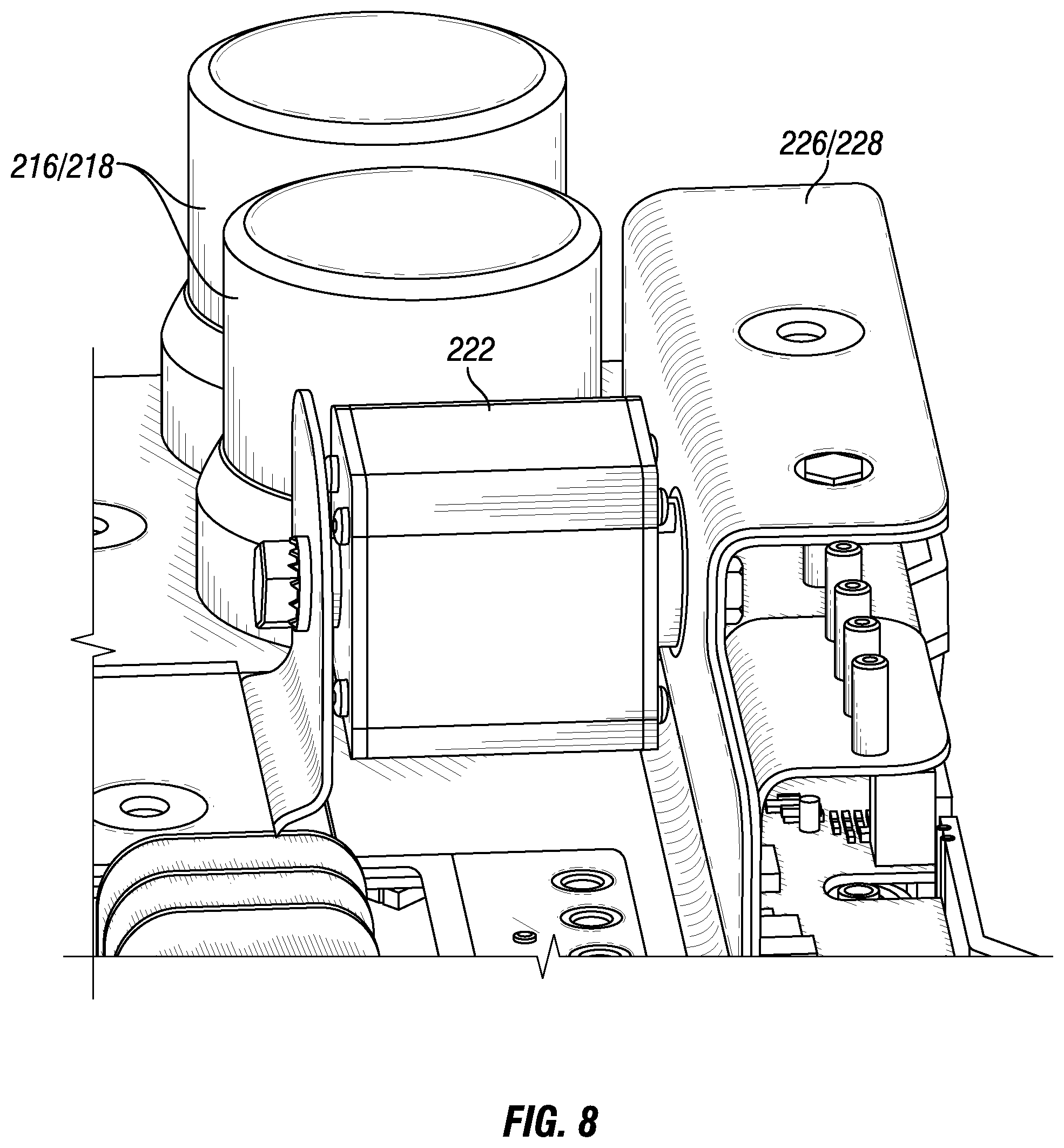
[0073] FIG. 7 shows a non-limiting example of interactions between a main fuse and laminated layers.
[0074] FIG. 8 shows closer detail of a non-limiting example of interactions between a main fuse and laminated layers.
[0075] FIG. 9 depicts an embodiment detailed view of a side section of the laminated layers.
[0076] FIG. 10 shows a top view of a non-limiting example apparatus.
[0077] FIG. 11 shows an alternate side view of a non-limiting example apparatus.
[0078] FIG. 12 depicts an embodiment configuration showing a main fuse coupled to laminated layers on a bottom side of the main fuse.
[0079] FIG. 13 depicts an embodiment configuration showing a main fuse coupled to laminated layers on a bottom side of the main fuse with thermal fins.
[0080] FIG. 14 depicts an embodiment configuration showing a main fuse coupled to laminated layers on a bottom side of the main fuse with features for enhanced heat flow.
[0081] FIG. 15 depicts an alternate embodiment configuration showing a main fuse coupled to laminated layers on a bottom side of the main fuse with features for heat flow.
[0082] FIG. 16 depicts an alternate embodiment configuration showing a main fuse coupled to laminated layers on a bottom side of the main fuse with features for heat flow.
[0083] FIG. 17 depicts an alternate embodiment configuration showing a main fuse coupled to laminated layers on a bottom side of the main fuse with features for heat flow.
[0084] FIG. 18 shows a non-limiting example system including a PDU positioned within a battery pack housing or enclosure.
[0085] FIG. 19 shows a non-limiting example system including a PDU in a coolant loop for a heat transfer system.
[0086] FIG. 20 shows a non-limiting example apparatus for providing additional protection against fuse nuisance faults and system failures.
[0087] FIG. 21 depicts an embodiment illustrative data for implementing a system response value.
[0088] FIG. 22 depicts a non-limiting example apparatus to measure current through a fuse utilizing active current injection.
[0089] FIG. 23 depicts a non-limiting example apparatus to determine a null offset voltage and/or diagnose a system component.
[0090] FIG. 24 depicts a non-limiting example apparatus to provide for digital filtering of a current measurement through a fuse circuit.
[0091] FIG. 25 depicts a non-limiting example fuse circuit that may be present on a PDU.
[0092] FIG. 26 depicts an embodiment of a fuse circuit with a contactor.
[0093] FIG. 27 depicts an embodiment fuse circuit including a plurality of fuses.
[0094] FIG. 28 depicts a fuse circuit with fuses in parallel with a contactor.
[0095] FIG. 29 depicts illustrative data showing a fuse response to a drive cycle for a vehicle.
[0096] FIG. 30 depicts a non-limiting example system including a power source and s load with a fuse electrically disposed between the load and the source.
[0097] FIG. 31 depicts a non-limiting example apparatus to determine an offset voltage to adjust a fuse current determination.
[0098] FIG. 32 depicts a non-limiting example apparatus is depicted to provide unique current waveforms to improve fuse resistance measurement for a PDU.
[0099] FIG. 33 depicts a non-limiting example procedure to provide unique current waveforms to improve fuse resistance measurement for a PDU.
[0100] FIG. 34 depicts a non-limiting example procedure to conduct a number of injection sequences.
[0101] FIG. 35 depicts an illustrative injection characteristic for an example test.
[0102] FIG. 36 depicts a schematic diagram of a vehicle having a PDU.
[0103] FIG. 37 depicts a schematic flow diagram of a procedure to utilize a parallel thermal fuse and pyro-fuse.
[0104] FIG. 38 depicts a schematic diagram of a vehicle having a PDU.
[0105] FIG. 39 depicts a schematic flow diagram of a procedure to operate a thermal fuse bypass.
[0106] FIG. 40 depicts a schematic diagram of a vehicle having a PDU.
[0107] FIG. 41 depicts a schematic flow diagram of a procedure to operate a thermal fuse bypass.
[0108] FIG. 42 depicts a schematic diagram of a vehicle having a PDU.
[0109] FIG. 43 depicts a schematic flow diagram of a procedure to operate parallel thermal fuses.
[0110] FIG. 44 depicts a schematic diagram of a vehicle having a PDU.
[0111] FIG. 45 depicts a schematic flow diagram of a procedure to selectively configure a current protection circuit.
[0112] FIG. 46 depicts a schematic diagram of a vehicle having a PDU.
[0113] FIG. 47 depicts a schematic flow diagram of a procedure to determine a fuse event value, and to respond thereto.
[0114] FIG. 48 depicts a schematic diagram of a vehicle having a PDU.
[0115] FIG. 49 depicts a schematic flow diagram of a procedure to determine current flow through a number of fuses.
[0116] FIG. 50 depicts a schematic diagram of a vehicle having a PDU.
[0117] FIG. 51 depicts a schematic flow diagram of a procedure to operate a thermal fuse in series with a contactor.
[0118] FIG. 52 depicts a schematic flow diagram of a procedure to re-connect a contactor.
[0119] FIG. 53 depicts a schematic diagram of a vehicle having a PDU.
[0120] FIG. 54 depicts a schematic diagram of a vehicle having a PDU.
[0121] FIG. 55 depicts a schematic diagram of a vehicle having a PDU.
[0122] FIG. 56 depicts a schematic flow diagram of a procedure to determine a null offset voltage.
[0123] FIG. 57 depicts a schematic diagram of an apparatus for determining an offset voltage.
[0124] FIG. 58 depicts a schematic flow diagram of a procedure to determine an injected current value.
[0125] FIG. 59 depicts a schematic flow diagram of a procedure to calibrate a fuse resistance algorithm.
[0126] FIG. 60 depicts a schematic flow diagram of a procedure to determine a fuse resistance using a unique current waveform.
[0127] FIG. 61 depicts a schematic diagram of a vehicle having a current protection circuit.
[0128] FIG. 62 depicts a schematic diagram of a vehicle having a current protection circuit.
[0129] FIG. 63 depicts a schematic diagram of a vehicle having a current protection circuit.
DETAILED DESCRIPTION
[0130] Referencing FIG. 1, an example system 100 is schematically depicted including a power distribution unit (PDU) 102 operationally positioned between a power source 104 and a load 106. The power source 104 may be any type--including at least a battery, generator, and/or capacitor. The power source 104 may include multiple sources or lines of power, which may be distributed according to the type of power (e.g., a battery input separated from a generator input) and/or may be distributed according to the devices powered (e.g., auxiliary and/or accessory power separated from main load power such as motive force power, and/or divisions within the accessories, divisions within the motive force power, etc.). The load 106 may be any type, including one or more motive force loads (e.g., to individual drive wheel motors, to a global motive drive motor, etc.), one or more accessories (e.g., on-vehicle accessories such as steering, fan, lights, cab power, etc.). In certain embodiments, the PDU 102 provides for ease of integration of the electrical system of the application including the system 100, such as by utilizing uniform input and output access, grouping all power distribution into a single box, single area, and/or to a single logically integrated group of components. In certain embodiments, the PDU 102 provides for protection of the electrical system, including fusing and/or connection or disconnection (manual and/or automated) of the electrical system or individual aspects of the electrical system. In certain embodiments, one or more power sources 104 may be high voltage (e.g., motive power sources, which may be 96V, 230V-360V, 240V, 480V, or any other value) or low voltage (e.g., 12V, 24V, 42V, or any other value). In certain embodiments, one or more power sources 104 may be a direct current (DC) power source or an alternating current (AC) power source, including multi-phase (e.g., three phase) AC power. In certain embodiments, the PDU 102 is a pass-through device, providing power to the load 106 approximately as configured by the power source 104--for example only as affected by sensing and other operations from the PDU 102 that are not provided for power configuration. In certain embodiments, the PDU 102 may include power electronics, for example rectifying, adjusting voltage, cleaning up noisy electrical power, etc. to provide selected electrical power characteristics to the load 106.
[0131] Referencing FIG. 2, a more detailed view of an example PDU 102 is schematically depicted. The example PDU 102 includes a main power source 202 (e.g., high voltage, main load power, motive power, etc.) which may be provided by one or more power sources 104, and an auxiliary power source 204 (e.g., auxiliary, accessory, low voltage, etc.) which may be provided by one or more power sources 104. The example PDU 102 depicts a single main power source 202 and a single auxiliary power source 204, but a given application may include one or more main power sources 202, and may include separated auxiliary power sources 204 and/or omit auxiliary power sources 204.
[0132] The example PDU 102 further includes a coolant inlet 206 and a coolant outlet 204. The provision of coolant to the PDU 102 is optional and may not be included in certain embodiments. The coolant may be of any type according to availability in the application, including for example an on-vehicle coolant available (e.g., engine coolant, transmission coolant, a coolant stream associated with an auxiliary device or other power components such as a power source 104, etc.) and/or may be a coolant dedicated to the PDU 102. Where present, the amount of cooling provided by the coolant may be variable--for example by changing an amount of coolant flowing through a coolant loop through the PDU 102--such as by operating hardware (e.g. a valve or restriction) within the PDU 102, providing a request for a coolant flow rate to another device in the system, etc.
[0133] The example PDU 102 further includes a main power outlet 210 and an auxiliary power outlet 212. As described preceding, the PDU 102 may include multiple main power outlets 210, and/or divided, multiple, multiplexed, and/or omitted auxiliary power outlets 212. The example PDU 102 is a pass-through power device where, except for effects on the power due to sensing and/or active diagnostics, the power outlets 210, 212 have approximately the same electrical characteristics of the corresponding power inlets 202, 204. However, the PDU 102 can include power electronics (solid state or otherwise) to configure power in any desired manner.
[0134] The example PDU 102 further includes a controller 214 configured to functionally execute certain operations of the PDU 102. The controller 214 includes and/or is communicatively coupled to one or more sensors and/or actuators in the PDU 102, for example to determine current values, voltage values, and/or temperatures of any power source or input, fuse, connector, or other device in the PDU 102. Additionally or alternatively, the controller 214 is communicatively coupled to the system 100 including the PDU 102, including for example a vehicle controller, engine controller, transmission controller, application controller, and/or network device or server (e.g., a fleet computer, cloud server, etc.). The controller 214 may be coupled to an application network (e.g., a CAN, a datalink, a private or public network, etc.), an outside network, and/or another device (e.g., an operator's portable device, an in-cab computer for a vehicle, etc.). The controller 214 is depicted schematically as a single stand-alone device for convenience of illustration. It will be understood that the controller 214 and/or aspects of the controller 214 may be distributed across multiple hardware devices, included within another hardware device (e.g., a controller for the power source, load, vehicle, application, etc.), and/or configured as hardware devices, logic circuits, or the like to perform one or more operations of the controller 214. The PDU 102 is depicted schematically as a device within a single enclosure, but may be within a single enclosure and/or distributed in two or more places within an application. In certain embodiments, the inclusion of the PDU 102 within a single enclosure provides certain advantages for integration, reduction of footprint, and/or simplification of interfaces. Additionally or alternatively, inclusion of the PDU 102 in more than one location in an application is contemplated herein, and/or the inclusion of more than one PDU 102 within an application is contemplated herein.
[0135] The example PDU 102 includes a main contactor 216 selectively controlling the main power throughput of the PDU 102. In the example, the main contactor 216 is communicatively coupled to and controlled by the controller 214. The main contactor 216 may additionally be controllable manually, and/or other main contactors 216 may be in-line for the main power that are controllable manually. An example main contactor 216 includes a solenoid (or other coil-based) contactor, such that energizing the solenoid provides for either connected main power (e.g., normally open, or power is disconnected when not energized) and/or energizing the solenoid provides for disconnected main power (e.g., normally closed, or power is connected when not energized). The characteristics of the system 100, including design choices about whether power should be active when controller 214 power fails, servicing plans, regulations and/or policies in place, the consequences of power loss for the system 100, the voltage typically carried on the main power source, the availability of a positive manual disconnect option, and the like, may inform or dictate the decision of whether the main contactor 216 is normally open or normally closed. In certain embodiments, the main contactor 216 may be a solid state device such as a solid state relay. Where more than one main contactor 216 is present, the various contactors may include the same or distinct hardware (e.g., one is a solenoid and one is a solid state relay), and/or may include the same or distinct logic for being normally open or normally closed. The main contactor 216 may be additionally controllable by devices outside the PDU 102--for example a keyswitch lockout, another controller in the system 100 having access to control the main contactor 216, etc., and/or the controller 214 may be responsive to outside commands to open or close the main contactor 216, and/or additional contactors in-line for the main power may be responsive to devices outside the PDU 102.
[0136] The example PDU 102 includes an auxiliary contactor 218 selectively controlling the auxiliary power throughput of the PDU 102. In the example, the auxiliary contactor 218 is communicatively coupled to and controlled by the controller 214. The auxiliary contactor 218 may additionally be controllable manually, and/or other auxiliary contactor 218 may be in-line for the auxiliary power that are controllable manually. An example auxiliary contactor 218 includes a solenoid (or other coil-based) contactor, such that energizing the solenoid provides for either connected auxiliary power (e.g., normally open, or power is disconnected when not energized) and/or energizing the solenoid provides for disconnected auxiliary power (e.g., normally closed, or power is connected when not energized). The characteristics of the system 100, including design choices about whether power should be active when controller 214 power fails, servicing plans, regulations and/or policies in place, the consequences of power loss for the system 100, the voltage typically carried on the auxiliary power source(s), the availability of a positive manual disconnect option, and the like, may inform or dictate the decision of whether the auxiliary contactor 218 is normally open or normally closed. In certain embodiments, the auxiliary contactor 218 may be a solid state device such as a solid state relay. The auxiliary contactor 218 may be additionally controllable by devices outside the PDU 102--for example a keyswitch lockout, another controller in the system 100 having access to control the auxiliary contactor 218, etc., and/or the controller 214 may be responsive to outside commands to open or close the auxiliary contactor 218, and/or additional contactors in-line for the auxiliary power may be responsive to devices outside the PDU 102. In certain embodiments, auxiliary contactors 218 may be provided for each auxiliary line, for subsets of the auxiliary lines (e.g., four auxiliary power inputs, with 2, 3, or 4 auxiliary contactors 218), etc.
[0137] An example PDU 102 includes a current source 220, which may be an alternating current source, and/or which may be provided as solid state electronics on the controller 214. The current source 220 is capable of providing a selected current injection to the main power across a main fuse 222, for example as AC current, DC current, and/or controllable current over time. For example, the PDU 102 may include sensors such as voltage and/or current sensors on the main power, and the current source 220 provides an electrical connection to a power source (which may be an external power source and/or sourced through the controller) in a manner configured to inject the desired current to the main power. The current source 220 may include feedback to ensure the desired current is injected, for example to respond to system noise, variability, and aging, and/or may apply the nominal electrical connection to inject current, and the controller 214 determines sensor inputs to determine what current was actually injected on the main power. The example PDU 102 depicts a current source 220 associated with the main fuse 222, but the PDU 102 may further include one or more current sources 220 associated with any one or more of the fuses 222, 224 in the PDU 102, including across fuses individually, in subsets, or across all of the fuses (subject to compatibility of power on the fuses--for example simultaneous current injection across electrically coupled fuses should generally be avoided) at once. It can be seen that the inclusion of additional current sources 220 provides for greater resolution in injecting current across individual fuses and in managing variation of the fuses over time, which the inclusion of fewer current sources 220 reduces system cost and complexity. In certain embodiments the current source 220 is configured to selectively inject current across each fuse in the PDU 102, and/or across each fuse of interest, in a sequence or schedule, and/or as requested by a controller 214.
[0138] The example PDU 102 includes the main fuse 222 and the auxiliary fuses 224. The main fuse 222 or fuses are associated with the main power, and the auxiliary fuses 224 are associated with the auxiliary power. In certain embodiments, the fuses are thermal fuses, such as resistive devices that exhibit heating, and are intended to fail if a given current profile is exceeded in the associated power line. Referencing FIG. 3, a typical and non-limiting example response curve for a fuse is depicted. The curve 302 represents an application damage curve, depicting a current-time space over which some aspect of the application will be damaged if the curve is exceeded. For example, in the example application damage curve 302, if 10.times. rated current is exceeded for about 50 milliseconds, damage to some aspect of the application will occur. It will be understood that an application may contain many components, and that the components may differ in the application damage curve 302. Additionally, each fuse 222, 224 may be associated with distinct components having a different damage curve than other components. The curve 304 represents a control space, wherein in certain embodiments, the controller 114 provides control protection to keep the system from reaching the application damage curve 302 in the event of a fuse failure or off-nominal operation. The application damage curve 302 may be a specified value, for example a system requirement to be met, where exceedance of the application damage curve 302 does not meet the system requirement, although actual damage to components may be experienced at some other value in the current-time space. The curve 306 represents the fuse melting line for an illustrative fuse. At the position of the fuse melting line 306, the fuse temperature exceeds the fuse design temperature, and the fuse melts. However, the fuse continues conducting for a period of time after melting commences, as depicted by the fuse conduction line 308 (e.g., due to conduction through the melted material before the connection is broken, arcing, and the like). When the time-current space reaches the fuse conduction line 308, the fuse is no longer conducting on the power line, and the line is disconnected. It will be understood that specific system dynamics, fuse-to-fuse variability, fuse aging (e.g., induced mechanical or thermal degradation, changes in composition or oxidation, and the like), the exact nature of the current experienced (e.g., the rise time of the current), and other real-world variables will affect the exact timing of both fuse melting and fuse disconnection. However, even with a nominal fuse as depicted in FIG. 3, it can be seen that for very high currents, the nominal fuse conduction line 308, and even the fuse melting line 306, can cross the application damage curve 302--for example because certain dynamics of the fuse disconnection operation are less responsive (in the time domain) or unresponsive to the current applied at very high current values.
[0139] The example PDU 102 further includes a conduction layer 226 associated with the auxiliary power, and a conduction layer 228 associated with the main power. The conduction layers 226, 228 include the power couplings of the power lines to the fuses. In certain embodiments, the conduction layers 226, 228 are just wires or other conductive couplings between the fuses and the power connections to the PDU 102. Additionally or alternatively, conduction layers 226, 228 may include flat or laminated portions, for example with stamped or formed conductive layers, to provide power connections within the PDU 102, and/or portions of the conduction layers 226, 228 may include flat or laminated portions. Without limitation to any other disclosures provided herein, the utilization of flat or laminated portions provides for flexibility in the manufacture of the conduction layers 226, 228, flexibility in the installation and/or a reduced installed footprint of the conduction layers 226, 228, and/or provides for greater contact area between the conduction layers 226, 228 and portions of the PDU 102--for example the fuses, controller, contactors, or other devices within the PDU 102 where thermal and/or electrical contact between the conduction layers 226, 228 and the other devices are desired. The example conduction layers 226, 228 are depicted in association with the fuses, but the conduction layers 226, 228 may additionally or alternatively be associated with the controller 214 (e.g., power coupling, communications within or outside the PDU 102, coupling to actuators, coupling to sensors, and/or thermal coupling), contactors 216, 218, and/or any other device within the PDU 102.
[0140] Referencing FIG. 4, an example system 400 is a mobile application such as a vehicle. The example system 400 includes the high voltage battery 104 electrically coupled to high voltage loads 106 through the PDU 102. In the example system 400, an auxiliary prime mover, such as an internal combustion engine 402 (with associated conversion electronics, such as a generator, motor-generator, and/or inverter) is additionally coupled to the PDU 102. It is understood that the high voltage battery 104 and/or the auxiliary prime mover 402 may act as a power source or a load during certain operating conditions of the system 400, and additionally the high voltage loads 106 (e.g., electric motors or motor-generators coupled to the wheels) may act as a load or a source during certain operating conditions. The description of loads 106 and sources 104 herein is non-limiting, and references only nominal operation, ordinary operation, and/or operational conditions selected for conceptual description, even if the described load 106 and/or source 104 often, usually, or always operates in a mode that is not the described name. For example, the high voltage battery 104 may operate as a power source during motive operations where net energy is being taken from the battery, and/or as a load during charging operations, motive operations where the wheels or auxiliary prime mover are charging the battery, etc.
[0141] The example system 400 further includes a powertrain controller 404 to control operations of the powertrain, which may be associated with another component in the system 400, and/or part of another controller in the system (e.g., a vehicle controller, battery controller, motor or motor-generator controller, and/or engine controller). The example system 400 further includes a charger 406 coupled to the high voltage batter 404 through the PDU 102, and low voltage loads ("12V Auto Loads" in the example of FIG. 4) representing auxiliary and accessory loads in the system 400. One of skill in the art will recognize the system 400 as including a serial hybrid powertrain for a vehicle--for example where auxiliary power (e.g., the internal combustion engine) interacts only with the electrical system to re-charge batteries and/or provide additional real-time electrical power during operations, but does not mechanically interact with the drive wheels. Additionally or alternatively, a system may include a parallel hybrid system, where auxiliary power can interact mechanically with the drive wheels, and/or interact with the electrical system (either, or both). Additionally or alternatively, a system may be a fully electric system, where auxiliary power is not present, and/or where auxiliary power is present but does not interact with the high voltage/motive power system (e.g., an alternative power unit to drive accessories, refrigeration, or the like--which power may be communicated through the PDU 102 but separated from the motive power electrical system). In certain embodiments, motive systems such as vehicles experience highly transient load cycles--for example during acceleration, deceleration, stop-and-go traffic, emergency operations, and the like--and accordingly management of power in such system is complex, and certain devices such as fuses can be vulnerable to the highly transient load cycle. Additionally or alternatively, loss of operations for vehicles can result in costs for system down-time, loss or untimely delivery of cargo, and/or significant operational risks due to failures (e.g., stranding the operator and/or vehicle, loss of operations in traffic, loss of operations on a motor-way, etc.). In certain embodiments, other systems that may be hybrid electric and/or fully electric are additionally or alternatively subject to highly variable duty cycles and/or specific vulnerabilities to operational interruptions, such as, without limitation, pumping operations, process operations for a larger process (e.g., chemical, refining, drilling, etc.), power generation operations, mining operations, and the like. System failures for these and other operations may involve externalities such as losses associated with the process failure that go beyond the down-time for the specific system, and/or down-time for such systems can incur a significant cost.
[0142] Referencing FIG. 5, an example system is depicted including a PDU 102. The example PDU 102 has a number of auxiliary power connections (e.g., charging, power steering, vehicle accessories, and a load return for current detection, in the example), and a main motive/traction power connection. The example system 500 includes two high voltage contactors, one for each of the battery high side and low side, where in the example two high voltage contactors are controllable by the system control board but may be additionally or alternatively manual (e.g., a switch accessible by an operator). The system control board additionally can control a master disconnect that can disconnect all power through the PDU 102. The system 500 further depicts a power fuse bypass 502, controllable by the system control board, that supports certain operations of the present disclosure as described throughout. The system 500 depicts a power fuse bypass 502, but may additionally or alternatively include an auxiliary bypass for one or more of the auxiliary fuses, any subset of the auxiliary fuses, and/or for all of the auxiliary fuses together. The example system 500 includes an optional coolant supply and return coupling. The battery coupling in the system 500 depicts a 230V to 400V battery coupling, but the high voltage coupling may be any value. The system control board is depicted as communicatively coupled to a 12V CAN network, although the communicative coupling of the system control board to the surrounding application or system can be any network understood in the art, multiple networks (e.g., vehicle, engine, powertrain, private, public, OBD, etc.), and/or may be or may include a wireless network connection.
[0143] Referencing FIG. 6, an illustrative apparatus 1300 is depicted, which may include all or portions of a PDU 102. Any descriptions referencing interactions between the main fuse 222 and laminated layers 226/228 herein additionally or alternatively contemplate interactions between any fuses and/or connectors in the apparatus 1300, and/or any other component of a PDU 102 as described throughout the present disclosure. The example apparatus 1300 includes contactors 216/218 which may be high voltage contactors, and/or may be associated with various ones of the fuses 222, 224 in the apparatus 1300. The apparatus 1300 includes laminated layers 226/228, which may include conductive layers for certain aspects of the conductive circuitry in the apparatus 1300. The laminated layers 226/228 may additionally or alternatively provide stiffness and/or structural support for various components in the apparatus 1300. The laminated layers 226/228 may be configured to interact with any components in a manner desired to support the functions of the laminated layers 226/228, including structural functions, heat transfer functions, and/or electrical conductivity functions. The example laminated layers 226/228 interact with all contactors and fuses in the apparatus 1300, although laminated layers 226/228 can readily be configured to interact with selected ones of the contactors and/or fuses, and/or with other components in the apparatus, for example in a manner similar to a printed circuit board (PCB) design. The example apparatus 1300 is positioned on a L-bracket, which may be a final configuration, and/or may be a test configuration. In certain embodiments, the apparatus 1300 is enclosed in a dedicated housing, and/or enclosed in a housing of another device in a system 100--such as the battery housing. In certain embodiments, the apparatus 1300 includes a removable housing portion (e.g., a top portion, lid, etc.) for service and/or maintenance access to the components of the apparatus. The example apparatus 1300 includes connectors 1302--for example to provide power, datalink access, connections to the power source 104, connections to loads 106, connections to sensors (not shown), and/or any other type of connection to the system 100 or otherwise.
[0144] Referencing FIG. 7, an alternate view of an apparatus 1300 is depicted. The apparatus 1300 depicted in FIG. 7 shows the physical interaction between the main fuse 222 and the laminated layers 226/228 for an example embodiment. Referencing FIG. 8, a closer detail view of interactions between the main fuse 222 and the laminated layers 226/228 is depicted for an example embodiment. In the example of FIG. 8, it can be seen that the main fuse 222 includes a relatively large thermal contact area with the laminated layers 226/228 on a bottom side of the fuse, and a relatively small thermal contact area with the laminated layers 226/228 on the mounting sides (e.g., through the mounting components). The thermal contact area between the main fuse 222 and the laminated layers 226/228 is selectable, and in certain embodiments the mounting side or an open side of the main fuse 222 includes a greater thermal contact area, and/or the bottom side includes a large thermal contact area or is not in significant thermal contact with the laminated layers 226/228.
[0145] Referencing FIG. 9, a detail view of a side section of the laminated layers 226/228 is depicted. The laminated layers 226/228 in the example include an outer structural layer 1402 and an opposing outer structural layer (not numbered), with an interstitial space 1404 between the outer structural layers. In certain embodiments, conductive flow paths and/or thermal flow paths are provided in the interstitial space 1404 between the structural layers. It will be understood that the use of two outer structural layers 1402 provides certain mechanical advantages, including increased durability to shocks and minor impacts, denting of a layer, and bending or flexing of the PDU 102. Additionally or alternatively, the use of two outer structural layers 1402 provides for improved mechanical moments for certain types of stresses. Accordingly, in certain embodiments, the interstitial space 1404 is empty (e.g., it forms a gap), and/or negligible (e.g., the outer layers are sandwiched directly together at least in certain portions of the PDU 102), and nevertheless an improved design is achieved. In certain embodiments, the interstitial space 1404 includes thermally conductive members (e.g., high thermal conductivity paths at selected locations), electrically conductive members (e.g., high electrical conductivity paths at selected locations), active and/or convective thermal paths (e.g., coolant or other convective thermal materials that flow through selected paths in the interstitial space 1404), insulating materials (e.g., to direct electrical or heat flow, and/or to separate components or layers electrically and/or thermally), and/or dielectric materials (e.g., to improve electric isolation of components and/or layers).
[0146] Referencing FIG. 10, a top view of an example apparatus 1300 is depicted. The laminated layers 226/228 are distributed throughout the apparatus 1300, providing selectable support, thermal conductivity paths, and/or electrical conductivity paths, to any desired components in the apparatus. Referencing FIG. 11, a side detail view of the interactive space 1408 between the laminated layers 226/228 and the main fuse 222 is depicted. The interactive space includes thermally conductive paths between mount points on the main fuse 222 and the laminated layers 226/228. Additionally, the interstitial space 1404 between the layers is present, in the example, along both the bottom and side of the main fuse 222. Accordingly, desired thermal transfer and/or electrical communication between the main fuse 222 and the interstitial layer 226/228 (and thereby with any other selected components in the apparatus 1300) is available as desired. In certain embodiments, greater thermal and/or electrical coupling between the main fuse 222 and the laminated layers 226/228 is provided--for example by running the laminated layers 226/228 along the housing of the main fuse 222 rather than offset from the housing, and/or by providing a thermally conductive connection (e.g., thermal grease, silicone, and/or contact utilizing any other thermally coupling material such as a metal or other conductor) between the main fuse 222 and the laminated layers 226/228.
[0147] Referencing FIG. 12, a main fuse 222 coupled to laminated layers 226/228 on a bottom side of the main fuse 222 is depicted. The example of FIG. 12 depicts a thermally conductive layer 1406 disposed between the main fuse 222 and the laminated layers 226/228--for example thermal grease, silicone, a silicone pad, a mounted metal material, and/or any other thermally conductive layer understood in the art. In the example of FIG. 12, the increased effective thermal contact area provides for greater heat transfer away from the main fuse 222 when the main fuse 222 gets hotter than the laminated layer 226, 228. Additionally, the heat can be directed away by the inclusion of a thermally conductive material within the interstitial space 1404 (e.g., reference FIG. 14), including for example utilizing a conductive path the direct heat to a selected portion of a PDU housing, to an active cooling exchange, heating fins, or the like. In the example of FIG. 12, the support layers 226/228 that the fuse 222 is coupled to in FIG. 12 may additionally or alternatively include be only a single layer (e.g., not a laminated layer, and/or layers 226, 228 having no interstitial space 1404), a housing of the PDU 102, and/or another component in a system 100 such as a battery pack housing. In certain embodiments, the heat conductivity in FIG. 12 is enhanced by the laminated layers 226/228, for example by the inclusion of a highly conductive channel in the interstitial space 1404, which may be improved by the structural support, routing availability, and/or environmental isolation provided by the laminated layers 226/228. Referencing FIG. 13, in addition to the features depicted in FIG. 12, fins 1502 for improved heat transfer and/or structural rigidity are depicted upon the laminated layers 226/228 (which may be laminated layers, a single layer, a housing wall, etc.). In certain embodiments, the fins are oriented such that fluid flows past them in a direction to enhance heat transfer (e.g., oriented for improved effective flow area and/or turbulence generation in a liquid flow, to maximize effective area in a gas flow, and/or to allow natural convection of fluid--such as gas rising--to cause a high effective flow area of the fins 1502). In certain embodiments, for example where the support layers 226, 228 (and/or layer 226) is a portion of a housing, battery pack housing, or other device, the fins 1502 may instead be presented into ambient air, a forced air flow region, or in a region to be in contact with any selected fluid to facilitate heat transfer to the fluid.
[0148] Convective heat transfer, as utilized herein, includes any heat transfer path wherein convective heat transfer forms at least a portion of the overall heat transfer mechanism. For example, where a portion of the heat transfer is conductive (e.g., through a wall, thermal grease, etc.) into a flowing fluid (where generally convective heat transfer dominates), then the heat transfer mechanism is convective and/or includes a convective portion. In certain embodiments, heat transfer utilizing an active or passively flowing fluid include convective heat transfer as utilized herein. The heat transfer may be dominated by conduction under certain operating conditions, dominated by convection under certain operating conditions, and/or include contributing mixes of conductive and convective heat transfer under certain operating conditions.
[0149] Referencing FIG. 14, in addition to the features depicted in FIG. 12, a fluid flow 1602 through the interstitial space 1404 is provided, which in certain embodiments enhances the heat flow from the main fuse 222 to the laminated layers 226/228. The fluid flow 1602 may be a coolant (e.g., a vehicle, engine, battery pack, and/or transmission coolant, or other coolant source available in the system), and/or may be a dedicated coolant such as a closed system for the PDU 102 and/or power source 104. In certain embodiments, the fluid flow 1602 includes a gas (e.g., air, compressed air, etc.). In certain embodiments, coolant flow may be active (e.g., through a valve from a pressurized source, and/or pumped) or passive (e.g., configured to occur during normal operations without further control or input).
[0150] Referencing FIG. 15, a main fuse 222 is depicted having enhanced thermal connectivity to laminated layers 226, 228 (which may be laminated, a single layer, a housing, etc.). In the example, enhanced thermal conductivity is provided by a thermal coupling layer 1406, but may alternatively or additionally include positioning the layers 226, 228 in proximity to the main fuse 222, and/or providing another high conductivity path (e.g., a metal, etc.) to a selected location of the layer 226, 228 and/or the thermal coupling layer 1406. The embodiment of FIG. 15 provides additional heat transfer capability for the main fuse 222, similar to that depicted in FIG. 12, and the embodiments of FIGS. 12, 13, 14, and 15 may be fully or partially combined.
[0151] Referencing FIG. 16, a high conductivity thermal path 1702 to move heat out of the laminated layers 226/228 is depicted. The high conductivity thermal path 1702 may be combined with any other embodiments described throughout the present disclosure to control heat flow in a desired manner. In certain embodiments, the high conductivity thermal path 1702 is thermally coupled 1706 to another portion of the laminated layers 226, 228, to a housing, to a single layer, or to any other desired component in the PDU 102 or within thermal connectivity of the PDU 102. The portion of FIG. 16 receiving the transferred heat may additionally or alternatively be coupled to active or passive heat transfer components, include fins or other heat transfer enhancement aspects, and/or may be thermally coupled to a convective heat transfer component or fluid.
[0152] Referencing FIG. 17, the fluid flow 1602 is displaced from the portion of the laminated layers 226/228 in direct thermal contact to the main fuse 222. The example includes the fluid flow 1602 below the main fuse 222, and the main fuse 222 thermally coupled to the laminated layers 226/228 on the sides of the fuse, but the fluid flow 1602 may be on either side or both sides of the main fuse 222, with the main fuse 222 thermally coupled to another one of the sides and/or the bottom of the main fuse 222, and combinations of any of the foregoing. The descriptions of FIGS. 12 through 17 are described in the context of the main fuse 222, but the embodiments therein may apply to any one or more selected components of the PDU 102, including without limitation any fuse, connector, and/or controller positioned within the PDU 102.
[0153] Referencing FIG. 18, an example system includes the PDU 102 positioned within a battery pack housing or enclosure, where the battery cells (e.g., power source 104) are thermally coupled to a heating/cooling system 1802 present in the system. Additionally or alternatively, the PDU 102 may be thermally coupled to the battery cells 104, for example with conductive paths, at a housing interface, or the like, and/or the PDU 102 may be thermally isolated from the battery cells 104 and/or only in nominal thermal connectivity with the battery cells 104 (e.g., an arrangement where some heat transfer therebetween is expected, but without intentional design elements to increase the heat transfer between the PDU 102 and the battery cells 104). Referencing FIG. 19, an example system includes the PDU 102 in the coolant loop for the heat transfer system 1802, for example with thermal coupling aspects provided to transfer heat from the PDU 102 to the coolant loop and/or with the coolant loop including a flow branch in thermal contact with the PDU 102. The example in FIG. 19 depicts a series coolant arrangement between the battery cells 104 and the PDU 102, but any arrangement is contemplated herein including at least a parallel arrangement, a series arrangement with the PDU 102 contacted first, and/or mixed arrangements (e.g., portions of one of the battery cells 104 and the PDU 102 contacted, then all or a portion of the other, etc.).
[0154] An example procedure includes an operation to provide active and/or passive cooling to a temperature sensitive component on a PDU 102. The example procedure further includes cooling the temperature sensitive component sufficiently to extend a life of the component to a designed service life, to a predetermined maintenance interval, to a life and/or predetermined maintenance interval of the PDU 102 and/or a battery pack, and/or to reduce a temperature of a fuse to avoid thermal/mechanical damage to the fuse, a "nuisance fault" of the fuse (e.g., a failure of the fuse not occurring due to a designed protective mechanism of the fuse, such as over-current operation).
[0155] In certain embodiments, fuse design imposes complications on system--for example a fuse threshold may be desired for the fuse to engage between about 135% up to 300% of the system overcurrent threshold value. However, a fuse on the smaller end of the scale may fail due to thermal and/or mechanical fatigue over the life of the system, causing a "nuisance failure" or a fuse failure that is not due to the protective function of the fuse. Such failures cause high costs, down-time, degraded perception of the product embodying the system, potentially dangerous situations or stranding due to power loss, and the like. Designing a larger fuse to avoid nuisance failures can impose the external system to increased risk of an overcurrent event, and/or significant costs to upgrade the rest of the power system. Additionally, design of a system for multiple maximum power availabilities (e.g., one power system for two different power ratings) requires that the fuse plan be altered or designed to accommodate multiple systems. In certain embodiments, the same hardware may be utilized for different power ratings, and/or changed after the system is in operation, providing for an off-nominal fuse sizing for at least one of the multiple power ratings.
[0156] Referencing FIG. 20, an example apparatus 1900 for providing additional protection against fuse nuisance faults and system failures is described. The example apparatus 1900, for example implemented on the controller 214, includes a current event determination circuit 1902 that determines a current event 1904 is active or predicted to occur, where the current event includes a component experiencing (or about to experience) a wear event--such as a current value that will cause thermal and/or mechanical stress on the component but may not cause an immediate failure or observable damage. An example component includes the fuse, but may be any other component in the system including a battery cell, a switch or connector, a motor, etc. Another example current event includes a system failure value--for example a current value that will possibly or is expected to cause a system failure (e.g., a cable failure, connector failure, etc.).
[0157] The apparatus 1900 further includes a response determination circuit 1906 that determines a system response value 1910 to the current event 1904. Example and non-limiting responses include notifying an operator to reduce power, reducing power, notifying a system controller that a current event 1904 is present or imminent, opening a contactor on the circuit related to the event, delaying circuit protection, monitoring the event and a cause for response delay and responding at a later time, and/or scheduling a response according to an operating condition in the system. The apparatus 1900 further includes a response implementation circuit 1908, where the response implementation circuit 1908 determines communications and/or actuator responses according to the system response value 1910, and provides network communications 1912 and/or actuator commands 1914 to implement the system response value 1910. Example and non-limiting actuator responses include operating a contactor, operating an active coolant actuator to modulate thermal conduction away from the fuse, or the like.
[0158] Referencing FIG. 21, illustrative data 2000 for implementing a system response value 1910 is depicted. The illustrative data 2000 includes a threshold value 2002--for example a current, temperature, index parameter, or other value at which component wear and/or system failure is expected to occur, and utilized as a threshold by the current event determination circuit 1902--at least under certain operating conditions at a point in time for the system. It is understood that the current event determination circuit 1902 may utilize multiple thresholds, and/or dynamic thresholds, as described throughout the present disclosure. The curve 2004 represents the nominal system performance, for example the current, temperature, index parameter, or the like that will be experienced by the system in the absence of operations of the apparatus 1900. In the example, the response determination circuit 1906 determines that the threshold value 2002 will be crossed, and accounts for a contactor disconnection time 2008 (and/or an active coolant loop response time), commanding the contactor and/or increasing thermal conduction away from the fuse, in time to avoid crossing the threshold value 2002. The illustrative data 2000 depicts a resulting system response curve 2006, wherein the resulting system performance is kept below the threshold value 2002. The system may experience alternative response trajectories (e.g., the resulting system response curve 2006 may fall well below the threshold value 2002 depending upon the dynamics of the system, how long the contactor is kept open, etc.). Additionally or alternatively, the response determination circuit 1906 may nevertheless allow the threshold value 2002 to be crossed, for example according to any operations or determinations described throughout the present disclosure. In certain embodiments, the response determination circuit 1906 allows the threshold value 2002 to be crossed, but results in a lower peak value of the response, and/or a lower area under the response curve that is above the threshold value 2002, than would occur without the operations of the response determination circuit 1906.
[0159] An example procedure, which may be performed by an apparatus such as apparatus 1900, includes an operation to determine that a current event (or other response event) is exceeding or predicted to exceed a wear threshold value, and/or determining that the current event is exceeding or predicted to exceed a system failure value. In response to determining the current event is exceeding or predicted to exceed either value, the procedure includes an operation to perform a mitigating action. The component for the wear threshold value may be a fuse (e.g., the fuse is experiencing or expected to experience a current event that will cause mechanical stress, thermal stress, or high usage of the fuse life), a component in the system (e.g., a contactor, a cable, a switch, a battery cell, etc.), and/or a defined threshold value that is nominally determined (e.g., calibration for a value that is expected to be relevant to possible component damage, without being necessarily tied to a specific component). In certain embodiments, the wear threshold value and/or the system failure value are compensated for the age or wear state of the system or a component in the system (e.g., thresholds are reduced, and/or responses are increased, as the system ages).
[0160] Non-limiting mitigating actions, which may be system response values 1910, include, without limitation: 1) disconnecting a circuit having the wear component (e.g., the fuse, system component, and/or the specific power line experiencing the event); 2) notifying an operator to reduce a power request; 3) notifying a vehicle or powertrain controller of the current event; 4) adjusting or limiting available power to the operator; 5) delaying circuit protection (disconnection and/or power reduction) in response to circumstances (e.g., in traffic, moving vehicle, application type, notification from an operator that continued operation is required, etc.)--including allowing a component in the system to experience the underlying wear event and/or failure event; 6) continued monitoring and disconnecting the circuit (or reducing power, etc.) if the event persists and if later conditions allow; 7) scheduling the response according to an operating mode of the system (e.g., sport, economy, emergency, fleet operator (and/or policy), owner/operator (and/or policy), geographic policy, and/or regulatory policy); and/or 8) bypassing the wear component (e.g., bypassing current around a fuse as a response action).
[0161] In certain embodiments, the operation to determine that the current event is exceeding the wear threshold value and/or the system failure value is based upon a calculation such as: 1) determining the current through the circuit exceeds a threshold value (e.g., an amp value); 2) determining a rate of change of the current through the circuit exceeds a threshold value (e.g., an amp/second value); and/or 3) determining that an index parameter exceeds a threshold value (e.g., the index including accumulated amp-seconds; amp/sec-seconds; a counting index for periods above a threshold value or more than one threshold value; a counting index weighted by the instantaneous current value; an integrated current, heat transfer, and/or power value; and/or counting down or resetting these based on current operating conditions).
[0162] In certain embodiments, the operation to determine that the current event is exceeding the wear threshold value and/or the system failure value includes or is adjusted based upon one or more of: 1) a trip curve (e.g., a power-time or current-time trajectory, and/or an operating curve on a data set or table such as that represented in FIG. 3); 2) a fuse temperature model, including a first or second derivative of the temperature, and one or more temperature thresholds for scheduled and/or escalating response; 3) a measured battery voltage (e.g., current values may be higher as battery voltage lowers, and/or dynamic response of current may change causing changes for the wear threshold value, system failure value, and/or current event determination); 4) a first derivative of current, temperature, power demand, and/or an index parameter; 5) a second derivative of current, temperature, power demand, and/or an index parameter; 6) information from a battery management system (e.g., voltage, current, state of charge, state of health, rate of change of any of these, which parameters may affect current values, expected current values, and/or dynamic response of current values, causing changes for the wear threshold value, system failure value, and/or current event determination); 7) determination of and monitoring of contactor disconnect times, and accounting for the contactor disconnect time in determining the response to the current event; 8) utilizing ancillary system information and adjusting the response (e.g., a power request from operations that is expected to create an upcoming change, a supplemental restraint system active/deploying--open contactors (cut power); collision avoidance system active--keep contactors closed for maximum system control; and/or an anti-lock brake system and/or traction control system active--keep contactors closed for maximum system control). In certain embodiments, a degree of activation may also be considered, and/or system status may be communicated to the PDU--for example the system may report critical operation requiring power as long as possible, or shut-down operations requiring power to be cut as soon as possible, etc.
[0163] Referencing FIG. 22, an example apparatus 600 to measure current through a fuse utilizing active current injection is schematically depicted. The apparatus 600 includes the controller 214 having a number of circuits configured to functionally execute operations of the controller 214. The controller 214 includes an injection control circuit 602 that provides an injection command 604, where the current source 220 is responsive to the injection command 604. The controller 214 further includes an injection configuration circuit 606 that selects a frequency, amplitude, and/or waveform characteristic (injection characteristic 608) for the injection command 604. The controller 214 further includes a duty cycle description circuit 610 that determines a duty cycle 612 for a system including the controller 214, where the duty cycle includes a description of currents and voltages experienced by the fuse. In certain embodiments, the duty cycle description circuit 612 further updates the duty cycle 612, for example by observing the duty cycle over time, over a number of trips, over a number of operating hours, and/or over a number of miles traveled. In certain embodiments, the duty cycle description circuit 612 provides the duty cycle as an aggregated duty cycle, such as a filtered duty cycle, averaged duty cycle, weighted average duty cycle, bucketed duty cycle with a quantitative description of a number of operating regions, or the like, and selects or mixes a calibration from a number of calibrations 614, each calibration corresponding to a defined duty cycle.
[0164] An example procedure to determine fuse current throughput is described following. In certain embodiments, one or more aspects of the procedure may be performed by an apparatus 600. The procedure includes an operation to inject a current having a selected frequency, amplitude, and/or waveform characteristic into the circuit through the fuse, and to estimate the fuse resistance (including dynamic resistance and/or impedance) in response to the measured injected AC voltages and the injected current. In certain embodiments, the selected frequency, amplitude, and/or waveform characteristic is selected to provide for an acceptable, improved, or optimized measurement of the fuse resistance. For example, the base power current through the fuse to support operations of the application have a certain amplitude and frequency characteristic (where frequency includes both the power frequency if AC, and the long term variability of the amplitude if AC or DC). The injected current may have a selected frequency and/or amplitude to allow for acceptable detection of the fuse resistance in view of the base power current characteristics, and also selected to avoid interference with the operations of the application. For example, if the base power current is high, a higher amplitude of the injection current may be indicated, both to support measurement of the injected AC voltage, and because the base power current will allow for a higher injected current without interfering with the operations of the system. In another example, a frequency may be selected that is faster than current variability due to operations, that does not impinge upon a resonant frequency or harmonic frequency of a component in the system, or the like.
[0165] An example procedure includes storing a number of calibration values corresponding to various duty cycles of the system (e.g., current-voltage trajectories experienced by the system, bucketed time windows of current-voltage values, etc.), determining the duty cycle of the system, and selecting a calibration value from the calibration values in response to the determined duty cycle. The calibration values correspond to the current injection settings for the current injection source, and/or to filter values for digital filters to measure the fuse voltage and/or fuse current values. In certain embodiments, the duty cycle can be tracked during operations, and updated in real-time or at shutdown. In certain embodiments, an aggregated duty cycle description is stored, which is updated by data as observed. An example aggregated duty cycle includes a moving average of the duty cycle observed (e.g., a duty cycle defined as a trip, power on to power off cycle, operating time period, and/or distance traveled), a filtered average of the duty cycle (e.g., with selected filter constants to provide the desired response to a change--for example to respond within one trip, five trips, 30 trips, one day, one week, one month, etc.). In certain embodiments, the duty cycle updates occur with a weighted average (e.g., longer trips, higher confidence determinations, and/or operator selections or inputs may be weighted more heavily in determining the duty cycle).
[0166] A response indicates the period until the system is acting substantially based upon the changed duty cycle information, for example where calibration A is for a first duty cycle and calibration B is for the changed duty cycle, the system may be deemed to have responded to the change when 60% of calibration B is utilized, 90% of calibration B is utilized, 96% of calibration B is utilized, and/or when the system has switched over to calibration B. The utilization of multiple calibrations may be continuous or discrete, and certain aspects of the calibrations individually may be continuous or discrete. For example, where calibration A is selected, a particular amplitude (or trajectory of amplitudes), frequency (or trajectory of frequencies), and/or waveform (or number of waveforms) may be utilized, and where calibration B is selected, a different set of amplitudes, frequencies, and/or waveforms may be utilized. Where a duty cycle is positioned between A and B, and/or where the duty cycle response is moving between A and B, the system can utilize mixtures of the A and B duty cycles, and/or switch between the A and B duty cycles. In a further example, the switching between the A and B duty cycles can occur in a mixed fashion--for example where the current response is at 80% of B, then calibration B may be utilized 80% of the time and calibration A may be utilized 20% of the time. In certain embodiments, the calibration may be switched abruptly at a certain threshold (e.g., at 70% response toward the new calibration), which may include hysteresis (e.g., switch to calibration B at 80% of the distance between calibration A and B, but switch back only when at 40% of the distance between calibration A and B). In certain embodiments, certain aspects (e.g., the amplitude) may move continuously between calibrations, where other aspects (e.g., the waveform) utilize only one calibration or the other. In certain embodiments, indicators of quality feedback may be utilized to adjust the calibration response (e.g., where, during movement toward calibration B, the indicated fuse resistance appears to be determined with greater certainty, the system moves the response toward calibration B more quickly than otherwise, which may include utilizing more of calibration B than indicated by the current aggregated duty cycle, and/or adjusting the aggregated duty cycle to reflect a greater confidence that the duty cycle is going to be maintained).
[0167] Example amplitude selections include both the peak amplitude of the injected current, the adjustment from the baseline (e.g., higher increase than decrease, or the reverse), and/or the shape of amplitude generation (e.g., which may be in addition to or incorporated within the waveform selection). Additionally or alternatively, the amplitude for a given calibration may be adjusted throughout a particular current injection event--for example to provide observations at a number of amplitudes within the current injection event. Example frequency selections include adjusting the frequency of the periods of the current injection events, and may further include testing at a number of discrete frequencies, sweeping the frequencies through one or more selected ranges, and combinations of these. Example waveform selections include waveform selections to induce desired responses, to be more robust to system noise (e.g., variability in the base current, inductance and/or capacitance of components in the system, or the like), to enhance the ability of the current injection detection to isolate the injected current from the load current, and/or may include utilization of multiple waveforms in a given calibration to provide a number of different tests. In certain embodiments, where multiple amplitudes, frequencies, and/or waveforms are utilized, the injected AC voltage (and corresponding fuse resistance) can be determined by averaging measured parameters, by using higher confidence measurements, and/or by eliminating outlying measurements from the injected AC voltage determination.
[0168] According to the present description, operations to provide a high confidence determination of a fuse resistance value in a PDU 102 are described. In certain embodiments, the high confidence determination of the fuse resistance can be utilized to determine the fuse condition, to provide a high accuracy or high precision determination of current through the fuse and of power consumption by the system 100, and/or to perform system diagnostics, fault management, circuit management, or the like.
[0169] Referencing FIG. 23, an example apparatus 700 to determine a null offset voltage and/or diagnose a system component are schematically depicted. The example apparatus 700 includes a controller 214 having a fuse load circuit 702 that determines that no current is demanded for a fuse load 704. The example apparatus 700 further includes a null offset voltage determination circuit 706 that determines a null offset voltage 708 in response to the fuse load 704 indicating that no current is demanded. The example apparatus 700 further includes a component diagnostic circuit 710 that determines whether a component is degraded, failed, and/or in a fault or off-nominal condition in response to the null offset voltage 708, and determines fault information 716 in response to the determining whether a component is degraded, failed, and/or in a fault or off-nominal condition (e.g., fault counters, fault values, and/or component-specific information). Operations of the component diagnostic circuit 710 include comparing the null offset nominal voltage 708 to a null offset voltage threshold value 712, and/or performing operations to determine which component is causing an off-nominal null offset voltage 708. The example apparatus 700 further includes a null offset data management circuit 714 that stores the null offset voltage 708, and/or any diagnostic or fault information 706 such as fault counters, fault values, and/or indications of which component is causing the off-nominal null offset voltage 708. In certain embodiments, where contributions to the null offset voltage 708 are determined separately for certain components, an example null offset data management circuit 714 stores individual contributions of the null offset voltage 708 separately. In certain embodiments, the utilization of the null offset voltage 708 improves the accuracy of determining the fuse resistance from the injected current.
[0170] An example procedure to determine null offset voltage for a fuse current measurement system is described following. The example procedure may be performed by a system component such as an apparatus 700. Null offset voltages occur in a controller 214 due to individual offsets of op-amps and other solid state components in the controller 214, as well as due to part-to-part variations, temperature drift, and degradation of one or more components in the system over time. The presence of a null offset voltage limits the accuracy with which current measurement through a fuse is available, and can thereby limit the types of controls and diagnostics that can be performed in the system.
[0171] An example procedure includes an operation to determine that no current is demanded for a fuse load. Example operations to determine that no current is demanded for a fuse load include a recent key-on or key-off event for a vehicle (e.g., the vehicle is starting, powering down, is in an accessory position, and/or has not yet engaged power to the fuse of interest), observation of the fuse circuit, and/or by a status observation provided by another controller in the system (e.g., a powertrain controller is explicitly indicating that no power is being provided, is indicating a status inconsistent with power being provided, etc.). An example operation determines that no current is demanded for a fuse during a key-off event, and/or within a time period after a key-on event.
[0172] The example procedure further includes an operation to determine the null offset voltage in response to determining that no current is demanded for the fuse load, and an operation to store the null offset voltage. In certain embodiments, the stored null offset voltage is stored in non-volatile memory, for example to be utilized in a subsequent operation of the system. In certain embodiments, the null offset voltage is stored in a volatile memory and utilized for a current operation cycle. The stored null offset voltage may be replaced when a new value is determined for the null offset voltage, and/or updated in a scheduled manner (e.g., by averaging in or filtering in updated values, by holding new values for subsequent confirmation before being applied, etc.).
[0173] An example procedure further includes diagnosing a component of the system in response to the null offset voltage. For example, as the null offset voltage increases over time, a degradation of the controller 214 may be indicated, and a fault (visible or service available) may be provided to indicate that the controller 214 is operating off-nominally or failed. Additionally or alternatively, a contactor (e.g., the main contactor 216) may be diagnosed in response to the null offset voltage. In certain embodiments, further operations such as engaging another contactor in-line with the diagnosed contactor may be utilized to confirm which component of the system is degraded or failed. In certain embodiments, the controller 214 may cut power to one or more components within the controller 214 to confirm that the controller 214 components are causing the offset voltage. In certain embodiments, the procedure includes determining the individual contributions of components to the offset voltage--for example by separating the controller 214 contribution and the contactor contribution. In response to the offset voltage being above a threshold value and/or confirming which component of the system is causing the off-nominal offset voltage, the controller 214 may increment a fault value, set a fault value, and/or set a service or diagnostic value. In certain embodiments, the null offset voltage and/or any fault values may be made available to the system, to a network, and/or communicated to another controller on the network.
[0174] According to the present description, operations to provide a nominal offset voltage for high confidence determination of a fuse current and a fuse resistance value in a PDU 102 are described. In certain embodiments, the high confidence determination of the fuse resistance can be utilized to determine the fuse condition, to provide a high accuracy or high precision determination of current through the fuse and of power consumption by the system 100, and/or to perform system diagnostics, fault management, circuit management, or the like.
[0175] Referencing FIG. 24, an example apparatus 800 to provide for digital filtering of a current measurement through a fuse circuit is depicted schematically. In certain embodiments, where current is injected through a fuse, the measurement of the base power current and the injected AC current through the fuse are de-coupled utilizing a low-pass filter (pulling out the base power signal) and a high-pass filter (pulling out the injected current signal). Previously known systems utilize an analog filter system--for example constructed of capacitors, resistors, and/or inductive devices, that provide the selected filtering of the signal and thereby provide the separated base power signal and injected current signal. However, analog filter systems suffer from a number of drawbacks. First, analog systems are not configurable, are only configurable to a discrete number of pre-considered options, and/or are expensive to implement. Accordingly, a wide range of base power signals and injected AC current signals are not typically available for high accuracy determination of the fuse current with an analog filter system. Additionally, analog filter systems suffer from phase variance between the low-pass filter and the high-pass filter, and/or between the filtered output and the injected current signal. Accordingly, post-processing and/or acceptance of a less accurate signal are required, and accuracy is diminished on the measured current even with post-processing. Further, if the system has a component that has a base frequency or harmonic that interferes with the filter, the analog filter is not able to respond and will not provide reliable measurements. Because the frequency dynamics of the system can change over time, for example as components degrade, are service or replaced, and/or due to environmental or duty-cycle driven changes, even careful system design cannot fully resolve the inability of analog filters to respond to interference from frequency dynamics in the system. The example apparatus 800 includes a high-pass digital filter circuit 802 that determines the injected current value 804 for the fuse circuit by providing a high-pass filter operation on a measured fuse current 814, and a low-pass digital filter circuit 806 that determines the base power current value 808 for the fuse circuit by providing a low-pass filter operation on the measured fuse current. The example apparatus 800 further includes a filter adjustment circuit 812 that interprets a duty cycle 612 and/or an injection characteristic 608, and adjusts the filtering for the high-pass digital filter circuit 802 and/or the injection characteristic 608--for example by providing filter adjustments 816 such as providing distinct cutoff frequencies to ensure separation of the signals, to raise or lower cutoff frequencies to ensure a descriptive energy portion of the signal is captured, and/or to manipulate the filters to avoid a frequency or a harmonic in the system. While the example embodiment of FIG. 24 utilizes a digital filter, in certain embodiments the available controller processing resources and/or time response of digital filtering may lead certain systems to utilize analog filters and/or a combination of analog filters with digital filters.
[0176] An example procedure includes an operation to provide digital filters in a PDU 102 to determine base power and injected current values from a measured current value through the fuse. The example procedure further includes an operation to determine the base power by performing a low-pass filter operation on the measured current value, and to determine the injected current value by performing a high-pass filter operation on the measured current value. The example procedure further includes an operation to adjust parameters of the low-pass filter and/or the high-pass filter in response to a duty cycle of the system including the PDU 102 (including, for example, power, voltage, and/or current values passing through the fuse), and/or in response to an injection characteristic of the injected current through the fuse. The example procedure includes adjusting the parameters to improve the separation of the base power and/or injected current values, to improve the accuracy of determining the injected current amount, to adjust to a frequency and/or a harmonic of a component in the system in electrical communication with the fuse, and/or to respond to a system or environmental noise affecting one or both of the high-pass and low-pass filters.
[0177] According to the present description, operations to implement digital filters for de-convoluting a voltage characteristic and current measurement through a fuse are provided. The digital filtering allows for the system to provide a high confidence determination of a fuse current and a fuse resistance value in a PDU 102. In certain embodiments, the high confidence determination of the fuse resistance can be utilized to determine the fuse condition, to provide a high accuracy or high precision determination of current through the fuse and of power consumption by the system 100, and/or to perform system diagnostics, fault management, circuit management, or the like.
[0178] Fuses for highly transient load applications and/or high duty cycle variability applications, such as but not limited to electrical systems for mobile applications and vehicles experience a number of challenges. Load variation can change considerably throughout operations, including experiencing both high positive and high negative current operations, and often in a short period of time (e.g., acceleration and regenerative braking cycles in stop-and-go traffic; high load operation going up a hill followed by significant regeneration down the other side, etc.). Additionally, current transients and reversals can result in significant in-rush currents that are experienced by the fuse. Fuses are designed to fail at a protective current value, which is intended to correspond to a fuse temperature value. Because they are designed to fail at a relatively close value to the maximum current demands, they are consequently one of the most delicate physical parts in the system--both electrically and physically. Sub-critical current values and current transient values can cause the fuse to suffer thermal and mechanical stresses, both from temperatures experienced and temperature transients. Fuses subject to significant sub-critical cycling can fail--either by melting even though the designed failure current has not been exceeded, or by breaking due to mechanical stress. Mobile applications, as discussed throughout the present disclosure, are subject to particularly high costs and risks when a mission critical component such as a fuse fails (e.g., the vehicle generally does not have motive power available if a main power fuse fails). Additionally, mobile applications are subject to high transient loads through the motive power system.
[0179] Referencing FIG. 25, an example fuse circuit 2100 is depicted, which may be present on a PDU 102. The example fuse circuit 2100 may be associated with a main fuse, an auxiliary fuse, and/or a group of fuses or a subset of a group of fuses. The fuse circuit 2100 includes a contactor (C1) in parallel with the fuse (F1). During normal operations the contactor is open, and the current in the fuse circuit 2100 passes through the fuse. In certain embodiments, the contactor may include physical components (e.g., a solenoid and/or coil-based switch or relay), and/or the contactor may be a solid state relay. In certain embodiments, the contactor may be normally-open (e.g., power applied closes the contactor) or normally-closed (e.g., power applied opens the contactor). The example fuse circuit 2100 allows for the contactor to selectively bypass the fuse circuit, for example in accordance with operations of an apparatus 1900 (reference FIG. 20 and the corresponding disclosure).
[0180] Referencing FIG. 26, another embodiment of a fuse circuit 2200 is disclosed, with a contactor (C1) in series with a second fuse (F2), and the C1-F2 branch in parallel with a first fuse F1. The fuse circuit 2200 provides for additional flexibility and a number of additional features for operations of an apparatus 1900. For example, normal operation may be performed with the contactor closed, dividing current between F1 and F2 (in the resistance ratios of the two fuses). An example includes a fuse F2 with a low current threshold value, set such that the divided current would fail fuse F2 if the system design current is exceeded by a designed amount (e.g., between 135% and 300% of system design current--although any value is contemplated herein). The fuse F1 may be set at a very high value, allowing for the opening of the contactor to briefly increase the fusing capacity of the circuit but still be fused. Additionally or alternatively, fuse F2 may be a relatively cheap and/or accessible fuse, and being at a lower current threshold F2 is likely to suffer greater mechanical and thermal fatigue, and act as the failure point for the fuse circuit 2200, which may greatly extend the life of the fuse F1 which may be more expensive and/or less accessible. Additionally or alternatively, normal operation may be performed with the contactor open, with fuse F1 defining the ordinary fusing of the circuit. When a high transient or other current event occurs, the contactor is closed, and the branch C1-F2 shares the current load, keeping the fuse F1 within normal or lower wear operating conditions. In certain embodiments, fuses F1 and F2 may be similarly sized--for example to allow fuse F2 to operate as a backup fuse and to keep similar failure conditions in place for F1 and F2. Alternatively, fuse F2 may be smaller than fuse F1, allowing for alternate operations as described, the intermittent use of the C1-F2 circuit to take up some current to protect fuse F1, and/or to provide back-up fusing for F1--which may be at a reduced power limit for the system if the fuse F2 is smaller (e.g., as a de-rated mode of operation, and/or a limp-home mode of operation). Alternatively, fuse F2 may be larger than fuse F1, for example to allow fuse F2 to manage very high transient current conditions where it is desired that operation still continues. The utilization of a fuse circuit 2200 allows for a high degree of control of the fusing system, to be protective of the power system during nominal operation and still provide a high degree of capability during failure modes, for off-nominal operation, and/or during transient operation. In certain embodiments, a resistor may be provided on the C1-F2 branch, for example to control the current sharing load between F1 and F2 when the contactor C1 is closed.
[0181] Referencing FIG. 27, a fuse circuit 2300 includes a plurality of fuses F1, F2, F3, F4 depicted in parallel, with a corresponding contactor in series with each. An example fuse circuit 2300 is for auxiliary fuses, although fuse circuit 2300 can be any fuse, including a main fuse. The example fuse circuit 2300 allows for either the removal of fuses from operation--for example where one of the fuses is experiencing a transient event--or for the addition of fuses, such as when a high transient event occurs to share the current load. In certain embodiments, one or more of the fuses in the fuse circuit 2300 does not have an associated contactor, and is a primary load bearing fuse for the fuse circuit 2300. The relative sizing of the fuses in the fuse circuit 2300 may be according to any selected values, and will depend upon the purpose of the fuse circuit 2300 (e.g., to provide a limp-home feature, to provide additional capacity, to act as a back-up, and/or to allow for the cut-off of individual fuses in the system). Additionally or alternatively, any one or more of the fuses in fuse circuit 2300 may be positioned serially with a resistor, for example to control current load balancing. In certain embodiments, the fuses F1, F2, F3, F4 are not in parallel, and/or one or more of the fuses is not in parallel. Accordingly, the opening of a contactor for such a fuse will not shunt current to another one of the fuses. An example embodiment includes the contactors for fuses individually to allow for shutting down of certain system capability (e.g., due to a failure, high transient, or the like) without shutting down all system capability (e.g., a fuse supporting braking may remain active even in a high transient event, while an accessory fuse for non-critical systems may be cut off to protect the fuse and/or the system).
[0182] Referencing FIG. 28, a fuse circuit 2400 is depicted, similar to fuse circuit 2300, except that each fuse has a contactor in parallel, allowing for the shorting of the particular fuse while keeping current flowing on that fuse's path. In certain embodiments, the parallel path for each fuse may include an additional fuse and/or a resistor, such that when the fuses are connected in parallel, the load across each fuse circuit remains at least partially balanced. The embodiments of FIGS. 25 to 28 may be referenced as current protection circuits, and embodiments such as those depicted in FIGS. 25 to 28, and/or as described, allow for selectable configuration of the current protection circuit. Selectable configuration of the current protection circuit may include run-time operations (e.g., reconfiguring the current protection circuit in response to events or operating conditions) and/or design-time operations (e.g., allowing a same hardware device to support multiple power ratings, electrical connection configurations, and/or service event or upgrade changes).
[0183] Referencing FIG. 29, illustrative data 2500 showing a fuse response to a drive cycle for a vehicle is depicted. In the example, fuse current (e.g., the dashed line lower curve at times of 12 and 25 units) and fuse temperature (e.g., the solid line upper curve at times of 12 and 25 units) are depicted. It will be understood that another parameter describing the fuse performance and/or limits may be utilized, including at least any values described in the portion referencing FIG. 21. The operations of the drive cycle exhibit high transients where, in the example, the fuse temperature is expected to exceed the "fuse temperature avoidance limit"--for example, a temperature or temperature transient at which the fuse experiences mechanical stress. An apparatus 1900 may consider a number of thresholds for the fuse--for example a light wear threshold, a heavy wear threshold, and a potential failure threshold, which may be set at distinct values of the fuser performance indicator being utilized (e.g., temperature). In certain embodiments, more than one type of threshold value may be utilized--for example a threshold or set of thresholds for temperature, a second threshold or set of thresholds for temperature change with time (e.g., dT/dt), etc. In the example, an apparatus 1900 may take mitigating action at the transient points, for example bypassing the corresponding fuse briefly to avoid the transient and/or control the rate of transient experienced by the fuse.
[0184] Referencing FIG. 30, an example system 2600 include the power source 104 and load 106, with a fuse (F1) electrically disposed between the load 106 and the source 104. An operator provides a power request (accelerator pedal input), and an apparatus 1900 determines that the load request will exceed a threshold for the fuse (e.g., according to the current demand above temperature limit, or some other determination) but may further determine that the transient event will not otherwise exceed system operating condition limits. In the example, apparatus 1900 commands the contactor (C3) to close for a period of time before or during the transient to protect the fuse. The system 2600 depicts the high-side (C1) and low-side (C3) high voltage contactors (e.g., 216, 218 from system 100), which are distinct from the fuse bypass contactor C3.
[0185] Referencing FIG. 21, illustrative data 2000 for implementing a system response value 1910 is depicted. The illustrative data 2000 includes a threshold value 2002--for example a current, temperature, index parameter, or other value at which fuse wear and/or failure is expected to occur, and utilized as a threshold by the current event determination circuit 1902--at least under certain operating conditions at a point in time for the system. It is understood that the current event determination circuit 1902 may utilize multiple thresholds, and/or dynamic thresholds, as described throughout the present disclosure. The curve 2004 represents the nominal system performance, for example the current, temperature, index parameter, or the like that will be experienced by the fuse in the absence of operations of the apparatus 1900. In the example, the response determination circuit 1906 determines that the threshold value 2002 will be crossed, and accounts for a contactor connection/disconnection time 2008 (e.g., to bypass the fuse, engage a second fuse branch, and/or close off a more vulnerable fuse branch), commanding the contactor to connect or disconnect in time to avoid crossing the threshold value 2002. Additionally or alternatively, the response determination circuit 1906 may nevertheless allow the threshold value 2002 to be crossed, for example according to any operations or determinations described throughout the present disclosure--for example when a more critical system parameter requires the fuse to remain connected, and the fuse is allowed to experience the wear and/or failure event.
[0186] In certain embodiments, the operation to determine that the current event is exceeding the wear threshold value and/or the fuse failure value is based upon a calculation such as: 1) determining the current through the fuse exceeds a threshold value (e.g., an amp value); 2) determining a rate of change of the current through the fuse exceeds a threshold value (e.g., an amp/second value); 3) determining that an index parameter exceeds a threshold value (e.g., the index including accumulated amp-seconds; amp/sec-seconds; a counting index for periods above a threshold value or more than one threshold value; a counting index weighted by the instantaneous current value; an integrated current, heat transfer, and/or power value; and/or counting down or resetting these based on current operating conditions).
[0187] In certain embodiments, the operation to determine that the current event is exceeding the wear threshold value and/or the fuse failure value includes or is adjusted based upon one or more of: 1) a trip curve (e.g., a power-time or current-time trajectory, and/or an operating curve on a data set or table such as that represented in FIG. 3); 2) a fuse temperature model, including a first or second derivative of the temperature, and one or more temperature thresholds for scheduled and/or escalating response; 3) a measured battery voltage (e.g., current values may be higher as battery voltage lowers, and/or dynamic response of current may change causing changes for the wear threshold value, system failure value, and/or current event determination); 4) first derivative of current, temperature, power demand, and/or an index parameter; 5) second derivative of current, temperature, power demand, and/or an index parameter; 6) information from a battery management system (e.g., voltage, current, state of charge, state of health, rate of change of any of these, which parameters may affect current values, expected current values, and/or dynamic response of current values, causing changes for the wear threshold value, fuse failure value, and/or current event determination); 7) determination of and monitoring of contactor connection or disconnection times, and accounting for the contactor connection or disconnection time in determining the response to the current event; 8) utilizing ancillary system information and adjusting the response (e.g., collision avoidance system active--allow the fuse to fail, and/or bypass the fuse allowing potential damage to the system, to keep power flowing; anti-lock brake system and/or traction control system active--keep power flowing for maximum system control (degree of activation may also be considered, and/or system status communicated to the PDU--for example the system may report critical operation requiring power as long as possible, or shut-down operations requiring power to be cut as soon as possible, etc.)).
[0188] Referencing FIG. 20, an example apparatus 1900 to reduce or prevent fuse damage and/or a fuse failure is depicted. The example apparatus 1900 includes a current event determination circuit 1902, which may determine that current event 1904 indicates that a fuse threshold value (wear, failure, fatigue, or other threshold value) is exceeded or is predicted to be exceeded. The current event 1904 may be a current, temperature, or any other parameter described, for example, in relation to FIGS. 21, 29, and 30. The example apparatus 1900 further includes a response determination circuit 1906 that determines a system response value 1910--for example opening or closing one or more contactors in a fuse circuit (e.g., 2100, 2200, 2300, 2400, or any other fuse circuit or current protection circuit). The apparatus 1900 further includes a response implementation circuit 1908 that provides network communications 1912 and/or actuator commands 1914 in response to the system response value 1910. For example, the system response value 1910 may determine to close one or more contactors, and the actuator commands 1914 provides commands to the selected contactors which are responsive to the actuator commands 1914.
[0189] In certain embodiments, operations to bypass and/or engage one or more fuses are performed in coordination with a vehicle battery management system and/or an accelerator pedal input (or other load request indicator)--for example to time inrush currents that would be experienced on the fuses, to provide an indication to the battery management system or other vehicle power systems that momentary un-fused operation is going to occur, and/or that a higher fuse limit will be briefly applicable. In certain embodiments, during un-fused operation and/or higher fuse limit operation, the apparatus 1900 may operate a virtual fuse--for example if the experienced current is higher than predicted (e.g., it was predicted to exceed a fuse wear limit but be less than a system failure limit, but in fact appears that a system failure limit will be exceeded), the apparatus 1900 may operate to open a main high voltage contactor, re-engage the fuse, or make another system adjustment to protect the system in the absence of ordinarily available fusing operations.
[0190] Referencing FIG. 31, an example apparatus 900 to determine an offset voltage to adjust a fuse current determination are schematically depicted. The example apparatus 900 includes a controller 214 having a fuse load circuit 702 that determines that no current is demanded for a fuse load 704, and further determines that contactors associated with the fuse are open. The example apparatus 900 further includes an offset voltage(s) determination circuit 906 that determines offset voltages for components in the fuse circuit observed during the no current demanded portion of the operating cycle. In certain embodiments, the contactors remain open while pre-charge capacitors are still charging after a key-on cycle, whereupon the fuse load circuit 702 determines that no current is demanded for the fuse load 704. In certain embodiments, the contactors are opened during an operation of the system, and an example fuse load circuit 702 determines that no current is demanded for a fuse load 704, including potentially waiting for observed voltages to settle before determining that no current is demanded for the fuse load 704.
[0191] The example apparatus 900 further includes an offset data management circuit 914 that stores the offset voltages 906, and communicates current calculation offset voltages 904 for use in the system to determine current flow through the one or more fuses in the system. The current calculation offset voltages 904 may be the offset voltages 906 for the applicable components, and/or may be processed or conditioned values determined from the offset voltages 906.
[0192] An example procedure to determine an offset voltage for a fuse current measurement system is described following. The example procedure may be performed by a system component such as an apparatus 900. Offset voltages occur in a controller 214 due to individual offsets of op-amps and other solid state components in the controller 214, as well as due to part-to-part variations, temperature drift, and degradation of one or more components in the system over time. The presence of an offset voltage limits the accuracy with which current measurement through a fuse is available, and can thereby limit the types of controls and diagnostics that can be performed in the system.
[0193] An example procedure includes an operation to determine that no current is demanded for a fuse load. Example operations to determine that no current is demanded for a fuse load include a recent key-on or key-off event for a vehicle (e.g., the vehicle is starting, powering down, is in an accessory position, and/or has not yet engaged power to the fuse of interest), observation of the fuse circuit, and/or by a status observation provided by another controller in the system (e.g., a powertrain controller is explicitly indicating that no power is being provided, is indicating a status inconsistent with power being provided, etc.). An example operation determines that no current is demanded for a fuse during a key-off event, and/or within a time period after a key-on event.
[0194] The example procedure further includes an operation to determine the offset voltage in response to determining that no current is demanded for the fuse load, and an operation to store the offset voltage. In certain embodiments, the stored offset voltage is stored in non-volatile memory, for example to be utilized in a subsequent operation of the system. In certain embodiments, the offset voltage is stored in a volatile memory and utilized for a current operation cycle. The stored offset voltage may be replaced when a new value is determined for the offset voltage, and/or updated in a scheduled manner (e.g., by averaging in or filtering in updated values, by holding new values for subsequent confirmation before being applied, etc.).
[0195] According to the present description, operations to provide an offset voltage for components in the fuse circuit, for high confidence determination of a fuse current and a fuse resistance value in a PDU 102 are described. In certain embodiments, the high confidence determination of the fuse resistance can be utilized to determine the fuse condition, to provide a high accuracy or high precision determination of current through the fuse and of power consumption by the system 100, and/or to perform system diagnostics, fault management, circuit management, or the like.
[0196] Referencing FIG. 32, an example apparatus 1000 to provide unique current waveforms to improve fuse resistance measurement for a PDU 102 is schematically depicted. The example apparatus 1000 includes a fuse load circuit 702 that determines that no current is demanded for a fuse load 704, and further determines that contactors associated with the fuse are open. The example apparatus 1000 further includes an injection configuration circuit 606 that determines injection characteristics 608, including frequency, amplitude, and waveform characteristics for test injection currents through one or more fuses to be tested. The example apparatus 1000 further includes an injection control circuit 602 that injects current through the fuses according to the injection characteristics 608, and a fuse characterization circuit 1002 that determines one or more fuse resistance(s) 1004 in response to the measured values 1006 during the test. An example injection control circuit 602 waits for the determination of voltage offset values while the fuse load 704 is still zero, and the fuse characterization circuit 1002 further utilized the voltage offset values in determining the fuse resistance(s) 1004 for the fuses. In certain embodiments, the injection configuration circuit 606 determines injection characteristics 608 in response to the characteristics of the system (e.g., the inherent capacitance and/or inductance of the system, the size of the fuse, the current ranges of the system during operation, and/or the resistance range and/or desired precision to support operations determinations utilizing the fuse resistance value). In certain embodiments, a high accuracy of the fuse resistance supports diagnostics, fuse protection control, and/or high accuracy on battery state of charge determinations.
[0197] In certain embodiments, the fuse characterization circuit 1002 determines the fuse resistance(s) 1004 for a given response based upon a number of current injection events, each of which may have a distinct one or more of an amplitude, frequency, and/or waveform. Additionally or alternatively, frequency sweeping, amplitude sweeping, and/or waveform shape management may be manipulated between injection events and/or within a given injection event. The fuse characterization circuit 1002 determines the fuse resistance 1004 by determining, for example, an averaged resistance value determined over the course of the tests. In certain embodiments, the fuse characterization circuit 1002 utilizes only a portion of each test window--for example to allow circuit settling time after an injection characteristic 608 switch, to allow for the injection provision circuit (e.g., a solid state op-amp, PWM, relay, or the like, which is configured to provide a selected current through the fuse circuit) to settle after switching the injection characteristic 608, to utilize a selected amount of data from each of the tests (e.g., for weighting purposes), and the like. In certain embodiments, the fuse characterization circuit 1002 may exclude outlying data (e.g., two of the tests agree, but a third test provides a far different value), and/or data which appears to indicate a rapid change which may appear to not be valid data. In certain embodiments, filtering, moving averages, rolling buffers, counters for delay in switching values (e.g., to confirm that a new value appears to be a real change) and the like are applied by the fuse characterization circuit 1002 to the fuse resistance 1004 to smooth changing values of the fuse resistance 1004 over time and/or to confirm that new information is repeatable. In certain embodiments, each period or a group of periods of a given injection waveform may be treated as a separate data point for resistance determinations. In certain embodiments, for example where the amplitude is swept for a given waveform, and/or where the frequency is swept for a given waveform, the resistance contribution for a given period may also be weighted (e.g., higher amplitudes and/or lower frequencies provide for a lower designed area under the current-time curve--see, e.g. FIG. 35--which may provide a higher quantity of information about the resistance relative to a lower amplitude and/or higher frequency period of the same waveform). Additionally or alternatively, measurement confidence may be dependent upon the frequency and/or amplitude of the current injection, and accordingly resistance determinations for those injection events may be weighted accordingly (e.g., given lower weight with lower confidence, and higher weight with higher confidence). Additionally or alternatively, conformance of the current injection source may be dependent upon the frequency, amplitude, and/or waveform of the current injection, and accordingly resistance determinations for those injection events may be weighted accordingly, and/or adjusted by feedback on the injector outlet about what frequency, amplitude, and/or waveform was actually provided relative to what was commanded.
[0198] In certain embodiments, the resistance determinations made by the fuse characterization circuit 1002, including how the resistance is determined and the average indicated by a given test, depend upon the waveform and other parameters. For example, if a sine wave waveform is utilized, resistance may be determined from the area under the voltage and current curves, from an rms determination (for current and/or voltage), and/or from high resolution time slices within the voltage determinations utilizing the injected current characterization. Other waveforms will utilize similar techniques for determining the resistance. If the circuit exhibits significant impedance (e.g. from latent capacitance and/or inductance, and/or from components in communication with the circuit that exhibit impedance), the impedance can be calculated by varying the frequency and determining the common impedance effects between the tests. The availability of multiple tests utilizing varying amplitudes, waveforms, and/or frequency values ensures that high accuracy can be determined even for circuits with complex effects or that exhibit changes due to age, degradation, or component servicing or replacing. Further, adjusting the frequency throughout the tests, and/or sweeping the frequency for a given amplitude or waveform can assist in de-coupling the phase-shifted aspects of impedance (e.g., capacitance effects versus inductance effects) to more confidently determine a resistance for the fuse. Typically for a fuse circuit having a closely coupled current source, impedance will be minimal. The desired degree of accuracy for the resistance measurement, which may depend upon the diagnostics, battery state of charge algorithms, and/or fuse protection algorithms in use on the system, may also affect whether impedance must be accounted for, and accordingly the selection of injection characteristics 608 utilized.
[0199] It can be seen that the use of multiple injection characteristics 608 during a test leverages comparisons between the tests to de-couple system characteristics from the resistance determination, provides for a range of system excitement parameters to ensure that system characteristics do not dominate a single test, and overall increase the amount of information available for a test to develop statistical confidence in the determined resistance value. Also, manipulation of injection characteristics 608 allows for better averaging--for example to prepare waveforms with high confidence that the resistance calculation is correct such as utilizing frequency values that avoid resonant or harmonic frequencies in the system, provide a large area under the current-time (or voltage-time) curve, and/or provide for a stabilized system during the test to ensure that measurement is correct.
[0200] Additionally or alternatively, the fuse characterization circuit 1002 adjusts digital filter values before the test, between changes in injection characteristics 608 for the test, and/or dynamically during the test (e.g., where a frequency sweep, amplitude sweep, and/or waveform change is utilized during a given injection event). In certain embodiments, the measurement of the voltage out of the filter circuit utilizes a high-pass filter to determine the injection voltage (and/or current), and the filter characteristics can be manipulated in real time to provide for an appropriate filter, such as cutoff frequencies. The utilization of digital filters for measurement can also eliminate phase lags between different filter types--such as a low pass filter and a high pass filter (e.g., where the low pass filter determines base power current during operation, and/or confirms that base power current remains zero or negligible during the test).
[0201] Referencing FIG. 35, an illustrative injection characteristic 608 is depicted for an example test. The injection characteristic 608 includes a first injection portion having an amplitude of 10 current units (e.g., amps--but any current units are contemplated herein), a sinusoidal waveform, and a period of approximately 150 time units (e.g., execution cycles of the controller 214, milliseconds, seconds, or any other parameter). The units and values depicted in FIG. 35 are non-limiting examples, and are used to illustrate that sequential changes in the injection characteristic 608 can be applied. The injection characteristic 608 includes a second injection portion having an amplitude of 15 current units, a sawtooth waveform, and a period of approximately 250 time units. The injection characteristic 608 further includes a third injection portion having an amplitude of 5 current units, a near square waveform (a slightly trapezoidal waveform is depicted), and a period of approximately 80 time units. The embodiment depicted in FIG. 35 is non-limiting, and other features may be added to the test, including more or less than three distinct waveforms, gaps between waveforms, and adjustments within a waveform (including sweeping, stepping, or otherwise adjusting frequency or amplitude, and/or adjusting the waveform itself). The example of FIG. 35 shows a trajectory reversal between the first and second injection characteristic (e.g., decreasing sine wave to increasing sawtooth wave) and a continuation of the trajectory between the second and third injection characteristic (e.g., decreasing sawtooth wave to an increasing square wave), although any possibilities, including step changes of the current and the like, are contemplated herein.
[0202] Referencing FIG. 33, an example procedure 1100 to provide unique current waveforms to improve fuse resistance measurement for a PDU 102 is schematically depicted. The procedure 1100 includes an operation 1102 to confirm that the contactors are open (and/or to confirm that the fuse load is zero or intended to be zero), and an operation 1104 to perform a null voltage offset determination--for example to determine offset voltage of op-amps and other components of the controller 214 and/or in the system 100 electrically coupled to the fuse circuit. An example operation 1102 is commenced during a key-on or system startup event with the contactors open, although any operating condition meeting the criteria for operation 1102 may be utilized. The procedure 1100 further includes an operation 1106 to conduct a number of injection sequences--for example three sequences each having a distinct frequency, amplitude, and waveform. The operation 1106 may include more than three sequences, and one or more of the sequences may share a frequency, an amplitude, and/or a waveform. The operation 1106 may be configured to perform as many sequences as desired, and may be carried over multiple tests (e.g., where a test is interrupted by operations of the system or exceeds a desired time, the test may be continued on a later sequence initiated by operation 1102). The procedure 1100 further includes an operation 1108 to determine fuse resistance values for one or more of the fuses in the system. The procedure 1100 may be operated on individual fuses where hardware in the system is configured to support that, including across subsets of the fuses or the like.
[0203] Referencing FIG. 34, an example procedure 1106 to conduct a number of injection sequences is depicted. The example procedure 1106 includes an operation 1202 to adjust injection characteristics for a current injection source associated with the fuse(s) to be tested, and an operation 1204 to adjust filtering characteristics for one or more digital filters associated with measuring voltage and/or current values on the filtering circuit. The procedure 1106 further includes an operation 1206 to perform the injection sequence in response to the injection characteristic, and an operation 1208 to perform the filtering (e.g., thereby measuring the current and/or voltage on the fuse circuit in response to the injection events). The procedure 1106 further includes an operation 1210 to determine if the current injection sequence is completed, returning to continue the injection event at operation 1206 until the sequence is complete (at operation 1210 determining YES). For example, referencing FIG. 35, at time step 200 the operation 1210 would determine NO, as the sine wave portion of the test is still being performed. If the operation 1210 determines YES (e.g., in FIG. 35, where the sine wave portion transitions to the sawtooth portion), the procedure 1106 includes an operation 1212 to determine whether another injection sequence is desired, and returns to operation 1202 to adjust the injection sequence in response to operation 1212 determining YES (e.g., in FIG. 9, where the sine wave portion is completed and the sawtooth portion commences). In response to the operation 1212 determining NO (e.g., where the square wave portion is completed, and no further sequences are scheduled in the test), the procedure 1106 completes--for example returning to operation 1108 to determine the fuse resistance value from the test.
[0204] According to the present description, operations to provide varying waveforms for current injection, thereby enhancing determination of the fuse resistance value in a PDU 102 are described. In certain embodiments, the high confidence determination of the fuse resistance can be utilized to determine the fuse condition, to provide a high accuracy or high precision determination of current through the fuse and of power consumption by the system 100, and/or to perform system diagnostics, fault management, circuit management, or the like.
[0205] Referencing FIG. 36, an example system includes a vehicle 3602 having a motive electrical power path 3604; and a power distribution unit 3606 having a current protection circuit 3608 disposed in the motive electrical power path 3604. The example current protection circuit 3608 includes a first leg 3610 of the current protection circuit 3608 including a pyro-fuse 3620 (e.g., a controllable activated fuse that can be commanded to activate and open the first leg of the current protection circuit; a second leg 3612 of the current protection circuit 3608 including a thermal fuse 3622; and where the first leg 3610 and the second leg 3612 are coupled in a parallel arrangement (e.g., in a similar manner to the depiction of any one of FIGS. 26 to 28). The example system includes a controller 3614 having a current detection circuit 3616 structured to determine a current flow through the motive electrical power path 3614, and a pyro-fuse activation circuit 3618 structured to provide a pyro-fuse activation command in response to the current flow exceeding a threshold current flow value. The pyro-fuse 3620 is responsive to the pyro-fuse activation command, for example to activate and open the second leg 3612 upon command Upon activation of the pyro-fuse 3620, the second leg 3612 is opened, providing for normal fused operation on the first leg 3610 (e.g., thermal failure of the thermal fuse 3622 thereby opens the motive electrical power path 3604), and/or opening the motive electrical power path 3604 directly when a contactor 3626 in series with the thermal fuse 3622 is already opened.
[0206] Certain further aspects of an example system are described following, any one or more of which may be present in certain embodiments. An example system includes where a first resistance through the first leg 3620 and a second resistance through the second leg 3612 are configured such that a resulting current through the second leg 3612 after the pyro-fuse 3620 activates is sufficient to activate the thermal fuse 3622. For example, a high current event may be experienced such that, if the second leg 3622 were not drawing a portion of the high current event, the thermal fuse 3622 would be activated. In the example, the opening of the second leg 3612 will cause the current in the first leg 3620 to increase and activate the thermal fuse 3622. An example includes a resistor 3624 coupled in a series arrangement with the thermal fuse 3622, such that a resulting current through the second leg 3612 after the pyro-fuse 3620 activates is below a second threshold current flow value. For example, an under-sized thermal fuse 3622 may be utilized in the system, with the operating current through the second leg 3612 reduced by the resistor 3624. When the pyro-fuse 3620 opens, the current through the second leg 3612 is increased, but still reduced by the resistor 3624 to prevent high current transients in the motive electrical power path 3604, and still allowing sufficient current through the second leg 3612 to activate the thermal fuse 3622.
[0207] An example system includes a contactor coupled 3626 in a series arrangement with the thermal fuse 3622, the controller further including a contactor activation circuit 3628 structured to provide a contactor open command in response to at least one of the pyro-fuse activation command or the current flow exceeding the threshold current flow value. In certain embodiments, the contactor 3626 coupled in the series arrangement with the thermal fuse 3622 allows for control of the current through the second leg 3612, including opening the second leg 3612 to open the motive electrical power path 3604 in combination with activation of the pyro-fuse 3620. The resistor 3624 may additionally be utilized with the contactor 3626, for example reducing the current through the second leg 3612 when the pyro-fuse 3620 activates (e.g., where contactor 3626 dynamics may be slower than the pyro-fuse 3620 dynamics) An example includes a resistor 3624 coupled in a series arrangement with the pyro-fuse 3620, such that a resulting current through the first leg 3610 after the thermal fuse 3622 activates is below a second threshold current flow value--for example to reduce the current through the motive electrical power path 3604 if the thermal fuse 3622 activates when the pyro-fuse 3620 has not already activated (e.g., an unmeasured current spike, and/or a current spike occurring after a controller has failed and is unable to command the pyro-fuse 3620 to open). An example system includes a second thermal fuse (not shown) coupled in a series arrangement with the pyro-fuse 3620, such that a resulting current through the first leg 3610 after the thermal fuse 3622 activates is sufficient to activate the second thermal fuse. For example, the use of a second thermal fuse provides for all branches of the motive electrical power path 3604 to have fuses with physical responses present, avoiding failures due to loss of ability to detect currents in the system or to command a pyro-fuse 3620 to activate. In the example, the sizing of the thermal fuse 3622 and the second thermal fuse can be made to avoid thermal wear during normal operations, but sufficient such that either thermal fuse 3622 will readily protect the system when the other leg (the first leg 3610 or second leg 3612) is opened during high current events. It can be seen that embodiments of the system depicted in FIG. 36 provide for both the high controllability of a pyro-fuse 3620 to disconnect the power, along with the robust protection of a thermal fuse that will physically respond to high current values regardless of failures in current sensing or controller operation, as may occur during a system failure, vehicle accident, etc. Additionally, the utilization of the two legs 3610, 3612, including potentially current management therethrough with resistor(s) 3624 and/or contactor(s) 3626, allows for the utilization of fuses that can be sized to avoid thermal wear and/or nuisance failures over the life of the vehicle, while still providing for reliable power disconnection for high current events.
[0208] Referencing FIG. 37, an example procedure includes an operation 3702 to determine a current flow through a motive electrical power path of a vehicle; an operation 3704 to direct the current flow through a current protection circuit having a parallel arrangement, with a pyro-fuse on a first leg of the current protection circuit and a thermal fuse on a second leg of the current protection circuit; and an operation 3706 to provide a pyro-fuse activation command in response to the current flow exceeding a threshold current flow value.
[0209] Certain further aspects of an example procedure are described following, any one or more of which may be present in certain embodiments. An example procedure further includes an operation to configure a first resistance through the first leg and a second resistance through the second leg such that a resulting current through the second leg after the pyro-fuse activates is sufficient to activate the thermal fuse. An example procedure includes an operation to configure a second resistance through the second leg such that a resulting current through the second leg after the pyro-fuse activates is below a second threshold current flow value. An example procedure includes an operation to a contactor coupled in a series arrangement with the thermal fuse, the procedure further including providing a contactor open command in response to at least one of providing the pyro-fuse activation command or the current flow exceeding the threshold current flow value; and/or an operation to configure a second resistance through the second leg such that a resulting current through the second leg after the pyro-fuse activates is below a second threshold current flow value. An example procedure further including a resistor coupled in a series arrangement with the pyro-fuse such that a resulting current through the first leg after the thermal fuse activates is below a second threshold current flow value; and/or further including a second thermal fuse coupled in a series arrangement with the pyro-fuse, such that a resulting current through the first leg after the thermal fuse activates is sufficient to activate the second thermal fuse.
[0210] Referencing FIG. 38, an example system includes a vehicle 3802 having a motive electrical power path 3804; a power distribution unit 3806 having a current protection circuit 3808 disposed in the motive electrical power path 3804, where the current protection circuit includes a first leg 3810 of the including a thermal fuse 3820 and a second leg 3812 including a contactor 3822. The first leg 3810 and the second leg 3812 are coupled in a parallel arrangement. The system includes a controller 3614 having a current detection circuit 3816 structured to determine a current flow through the motive electrical power path 3804; and a fuse management circuit 3818 structured to provide a contactor activation command in response to the current flow. The contactor 3822 is responsive to the contactor activation command.
[0211] Certain further aspects of an example system are described following, any one or more of which may be present in certain embodiments. An example system includes where the contactor 3822 is open during nominal operations of the vehicle, and where the fuse management circuit is structured to provide the contactor activation command as a contactor closing command in response to determining that the current flow is a above a thermal wear current for the thermal fuse 3820; and/or where the fuse management circuit is further structured to provide the contactor activation command as the contactor closing command in response to determining that the current flow is below a current protection value for the motive electrical power path 3804. An example system includes where the contactor 3822 is closed during nominal operations of the vehicle, and where the fuse management circuit is structured to provide the contactor activation command as a contactor opening command in response to determining that the current flow is above a current protection value for the motive electrical power path 3804. An example system includes where the fuse management circuit is further structured to provide the contactor activation command in response to the current flow by performing at least one operation selected from the operations consisting of: responding to a rate of change of the current flow; responding to a comparison of the current flow to a threshold value; responding to one of an integrated or accumulated value of the current flow; and responding to one of an expected or a predicted value of any of the foregoing. It can be seen that the embodiments of the system depicted in FIG. 38 allow for the utilization of an oversized fuse 3820 that will experienced reduced wear and increased life, while still allowing for circuit protection for moderate overcurrent (e.g., utilizing the contactor) and fused protection for high overcurrent values. It can be seen that the embodiments of the system depicted FIG. 38 allow for utilization of a nominally sized or undersized fuse 3820 that can reliably open the circuit at moderate overcurrent values, but experience reduced wear and increased life (e.g., by sharing current through the contactor branch).
[0212] Referencing FIG. 39, an example procedure includes an operation 3902 to determine a current flow through a motive electrical power path of a vehicle; an operation 3904 to direct the current flow through a current protection circuit having a parallel arrangement, with a thermal fuse on a first leg of the current protection circuit and a contactor on a second leg of the current protection circuit; and an operation 3906 to provide a contactor activation command in response to the current flow.
[0213] Certain further aspects of an example procedure are described following, any one or more of which may be present in certain embodiments. An example procedure further includes an operation to close the contactor in response to the current flow. An example procedure includes an operation to determine that the current flow is below a current protection value for the motive electrical power path before the closing the contactor. An example procedure includes at least one operation selected from the operations consisting of: responding to a rate of change of the current flow; responding to a comparison of the current flow to a threshold value; responding to one of an integrated or accumulated value of the current flow; and responding to one of an expected or a predicted value of any of the foregoing. An example procedure includes an operation to open the contactor in response to the current flow; an operation to determine that the current flow is above a current protection value for the motive electrical power path before opening the contactor; and/or an operation to open the contactor including performing any one or more of: responding to a rate of change of the current flow; responding to a comparison of the current flow to a threshold value; responding to one of an integrated or accumulated value of the current flow; and responding to one of an expected or a predicted value of any of the foregoing.
[0214] Referencing FIG. 40, an example system includes a vehicle 4002 having a motive electrical power path 4004; a power distribution unit 4006 having a current protection circuit 4008 disposed in the motive electrical power path 4004, where the current protection circuit includes a first leg 4010 of the current protection circuit 4008 including a thermal fuse 4020 and a second leg 4012 of the current protection circuit 4008 including a solid state switch 4022. The first leg 4010 and the second leg 4012 are coupled in a parallel arrangement. The example system includes a controller 4014 including a current detection circuit 4016 structured to determine a current flow through the motive electrical power path 4004 and a fuse management circuit 4018 structured to provide a switch activation command in response to the current flow. The solid state switch 4022 is responsive to the switch activation command. In certain embodiments, the system includes a contactor 4024 coupled to the current protection circuit 4008, where the contactor 4024 in the open position disconnects the current protection circuit 4008 (e.g., the contactor 4024 in series with both legs 4010, 4012), and/or the contactor 4024 in series with the solid state switch 4022 on the second leg 4012). Any contactor described throughout the present disclosure may, in certain embodiments, be a solid state switch instead of, or in series with, a conventional contactor device. Solid state switches are known to have rapid response and are robust to opening during high current events. However, solid state switches also experience a small leakage current, which may be acceptable in certain embodiments, or not acceptable in other embodiments. In certain embodiments, the utilization of a conventional contactor with a solid state switch allows for the rapid response time and survivability of the solid state switch, as well as the enforced zero current of a conventional contactor. In certain embodiments, the solid state switch is utilized to open the circuit first, and then the conventional contactor opens the circuit second, allowing for the avoidance of conditions where the conventional contactor opens under high current conditions.
[0215] Referencing FIG. 41, an example procedure includes an operation 4102 to determine a current flow through a motive electrical power path of a vehicle; an operation 4104 to direct the current flow through a current protection circuit having a parallel arrangement, with a thermal fuse on a first leg of the current protection circuit and a solid state switch on a second leg of the current protection circuit; and an operation 4106 to provide a switch activation command in response to the current flow.
[0216] Certain further aspects of an example procedure are described following, any one or more of which may be present in certain embodiments. An example procedure further includes an operation to close the solid state switch in response to the current flow; and/or determine that the current flow is below a current protection value for the motive electrical power path before the closing the solid state switch. For example, a current flow value or transient may be sufficiently high to cause degradation of the thermal fuse, but lower than a threshold where a system protection response from the thermal fuse is required. In certain embodiments, closing the solid state switch reduces the current flow and/or transient through the thermal fuse, reducing the wear and/or a nuisance failure of the thermal fuse. An example procedure includes an operation to close the solid state switch includes performing at least one operation such as: responding to a rate of change of the current flow; responding to a comparison of the current flow to a threshold value; responding to one of an integrated or accumulated value of the current flow; and responding to one of an expected or a predicted value of any of the foregoing. An example procedure includes an operation to open the solid state switch in response to the current flow; and/or determine that the current flow is above a current protection value for the motive electrical power path before opening the solid state switch. An example procedure includes an operation to open the solid state switch includes performing at least one operation selected from the operations consisting of: responding to a rate of change of the current flow; responding to a comparison of the current flow to a threshold value; responding to one of an integrated or accumulated value of the current flow; and responding to one of an expected or a predicted value of any of the foregoing. An example procedure includes an operation to open a contactor after the opening the solid state switch, where opening the contactor disconnects one of the current protection circuit or the second leg of the current protection circuit.
[0217] Referencing FIG. 42, an example system includes a vehicle having a motive electrical power path 4204; a power distribution unit 4206 having a current protection circuit 4208 disposed in the motive electrical power path 4204, where the current protection circuit includes a first leg 4220 of the current protection circuit 4208 including a first thermal fuse 4220, a second leg 4212 of the current protection circuit 4208 including a second thermal fuse 4222 and a contactor 4224, and where the first leg 4220 and the second leg 4212 are coupled in a parallel arrangement. The example system includes a controller, including: a current detection circuit 4216 structured to determine a current flow through the motive electrical power path 4204; and a fuse management circuit 4218 structured to provide a contactor activation command in response to the current flow. The contactor 4224 is responsive to the contactor activation command.
[0218] Certain further aspects of an example system are described following, any one or more of which may be present in certain embodiments. An example system includes where the contactor 4224 is open during nominal operations of the vehicle, and where the fuse management circuit 4218 is structured to provide the contactor activation command as a contactor closing command in response to determining that the current flow is a above a thermal wear current for the first thermal fuse 4220. An example system includes the fuse management circuit 4218 further structured to provide the contactor activation command as a contactor closing command in response to determining that the current flow is below a current protection value for the motive electrical power path 4204. An example system includes a vehicle operating condition circuit 4226 structured to determine an operating mode for the vehicle (e.g., moving, stopped, high performance, high economy, charging, quick charging, etc.), and where the fuse management circuit 4218 is further structured to provide the contactor activation command in response to the operating mode. An example system includes the fuse management circuit 4218 further structured to provide the contactor activation command as a contactor closing command in response to the operating mode including at least one operating mode selected from the operating modes consisting of: a charging mode; a quick charging mode; a high performance mode; a high power request mode; an emergency operation mode; and/or a limp home mode. An example system includes where the contactor 4224 is closed during nominal operations of the vehicle, and where the fuse management circuit 4218 is structured to provide the contactor activation command as a contactor opening command in response to determining that the current flow is above a current protection value for the motive electrical power path 4204. An example system includes where the contactor is closed during nominal operations of the vehicle, and where the fuse management circuit 4218 is structured to provide the contactor activation command as a contactor opening command in response to the operating mode; and/or where the fuse management circuit 4218 is further structured to provide the contactor activation command as a contactor opening command in response to the operating mode including at least one of an economy mode or a service mode. For example, during certain operating conditions such as an economy mode or during a service event, a reduced maximum power throughput through the motive electrical power path 4204 may be enforced, where the opening of the contactor 4224 is utilized to provide configured fuse protection for the reduced maximum power throughput.
[0219] Referencing FIG. 43, an example procedure includes an operation 4302 to determine a current flow through a motive electrical power path of a vehicle; an operation 4304 to direct the current flow through a current protection circuit having a parallel arrangement, with a first thermal fuse on a first leg of the current protection circuit and a second thermal fuse and a contactor on a second leg of the current protection circuit; and an operation 4306 to provide a contactor activation command in response to the current flow.
[0220] Certain further aspects of an example procedure are described following, any one or more of which may be present in certain embodiments. An example procedure further includes an operation to close the contactor in response to the current flow being above a thermal wear current for the first thermal fuse; and/or closing the contactor further in response to the current flow being below a current protection value for the motive electrical power path. An example procedure includes an operation to determine an operating mode for the vehicle, and providing the contactor activation command further in response to the operating mode. An example procedure includes an operation to provide the contactor activation command as a contactor closing command in response to the operating mode including at least one operating mode selected from the operating modes consisting of: a charging mode; a high performance mode; a high power request mode; an emergency operation mode; and a limp home mode. An example procedure includes an operation to provide the contactor activation command as a contactor opening command in response to determining that the current flow is above a current protection value for the motive electrical power path; and/or provide the contactor activation command as a contactor opening command in response to the operating mode including at least one of an economy mode or a service mode.
[0221] Referencing FIG. 44, an example system includes a vehicle 4402 having a motive electrical power path 4404; a power distribution unit 4406 having a current protection circuit 4408 disposed in the motive electrical power path 4404, where the current protection circuit includes: a first leg 4410 of the current protection circuit 4408 including a first thermal fuse 4420 and a first contactor 4424; a second leg 4412 of the current protection circuit 4408 including a second thermal fuse 4422 and a second contactor 4426; and where the first leg 4410 and the second leg 4412 are coupled in a parallel arrangement. The example system includes a controller 4414 including a current detection circuit 4416 structured to determine a current flow through the motive electrical power path 4404; and a fuse management circuit 4418 structured to provide a plurality of contactor activation commands in response to the current flow. The first contactor 4424 and the second contactor 4426 are responsive to the contactor activation commands, thereby providing a selected configuration of the current protection circuit 4408.
[0222] Certain further aspects of an example system are described following, any one or more of which may be present in certain embodiments. An example system includes where the current protection circuit further includes: one or more additional legs 4413, where each additional leg 4413 includes an additional thermal fuse 4423 and an additional contactor 4428; and where each additional contactor 4428 is further responsive to the contactor activation commands, thereby providing the selected configuration of the current protection circuit 4408. An example system includes a vehicle operating condition circuit 4430 structured to determine an operating mode for the vehicle, and where the fuse management circuit 4418 is further structured to provide the contactor activation commands in response to the operating mode. An example fuse management circuit 4418 is further structured to determine an active current rating for the motive electrical power path 4404 in response to the operating mode, and to provide the contactor activation commands in response to the active current rating. An example system includes where the first leg 4410 of the current protection circuit 4408 further includes an additional first contactor 4427 in a parallel arrangement with the first thermal fuse 4420, where the current detection circuit 4416 is further structured to determine a first leg current flow, where the fuse management circuit 4418 is further structured to provide the contactor activation commands further in response to the first leg current flow, and where the additional first contactor 4427 is responsive to the contactor activation commands. An example system includes the additional first contactor 4427 being open during nominal operations of the vehicle, and where the fuse management circuit 4418 is structured to provide the contactor activation commands including an additional first contactor closing command in response to determining that the first leg current flow is a above a thermal wear current for the first thermal fuse 4420. An example system includes the fuse management circuit 4418 structured to provide the additional first contactor closing command in response to determining at least one of: that the first leg current flow is below a first leg current protection value, or that the current flow is below a motive electrical power path current protection value. An example system includes where the additional first contactor 4427 is closed during nominal operations of the vehicle, and where the fuse management circuit 4418 is structured to provide the contactor activation commands including an additional first contactor opening command in response to determining at least one of: that the first leg current flow is above a first leg current protection value, or that the current flow is above a motive electrical power path current protection value. The example system may further include additional contactors 4428 positioned on any one or more of the legs 4410, 4412, 4413. Any one or more of the contactors 4424, 4426, 4428 may be configured in series and/or parallel with the associated thermal fuse 4420, 4422, 4423 on the associated leg.
[0223] Referencing FIG. 45, an example procedure includes an operation 4502 to determine a current flow through a motive electrical power path of a vehicle; an operation 4504 to direct the current flow through a current protection circuit having a parallel arrangement, with a first thermal fuse and a first contactor on a first leg of the current protection circuit, and a second thermal fuse and a second contactor on a second leg of the current protection circuit; and an operation 4506 to provide a selected configuration of the current protection circuit in response to the current flow through the motive electrical power path of the vehicle, where providing the selected configuration includes providing a contactor activation command to each of the first contactor and the second contactor.
[0224] Certain further aspects of an example procedure are described following, any one or more of which may be present in certain embodiments. An example procedure includes an operation further including at least one additional leg of the current protection circuit, each additional leg of the current protection circuit having an additional thermal fuse and an additional contactor, and where the providing the selected configuration of the current protection circuit includes providing a contactor activation command to each additional contactor. An example procedure includes an operation to determine an operating mode for the vehicle, and providing the selected configuration further in response to the operating mode; and/or an operation to determine an active current rating for the motive electrical power path in response to the operating mode, and where providing the selected configuration of the current protection circuit is further in response to the active current rating. An example procedure includes an operation to determine an active current rating for the motive electrical power path, and where providing the selected configuration of the current protection circuit is further in response to the active current rating. An example procedure includes an operation where the first leg of the current protection circuit further includes an additional first contactor in a parallel arrangement with the first thermal fuse, the procedure further including: determining a first leg current flow, and where providing the selected configuration further includes providing a contactor activation command to the additional first contactor; an operation to close the additional first contactor in response to determining that the first leg current flow is a above a thermal wear current for the first thermal fuse; an operation to close the additional first contactor further in response to determining at least one of: that the first leg current flow is below a first leg current protection value, or that the current flow is below a motive electrical power path current protection value; and/or an operation to open the additional first contactor in response to determining at least one of: that the first leg current flow is above a first leg current protection value, or that the current flow is above a motive electrical power path current protection value.
[0225] Referencing FIG. 46, an example system includes a vehicle 4602 having a motive electrical power path 4604; a power distribution unit 4606 having a current protection circuit 4608 disposed in the motive electrical power path 4604, where the current protection circuit 4608 includes a fuse 4610. The example system further includes a controller 4614 including a fuse status circuit 4616 structured to determine a fuse event value; and a fuse management circuit 4618 structured to provide a fuse event response based on the fuse event value.
[0226] Certain further aspects of an example system are described following, any one or more of which may be present in certain embodiments. An example system includes a fuse life description circuit 4619 structured to determine a fuse life remaining value, where the fuse event value includes a representation that the fuse life remaining value is below a threshold value, and where the fuse management circuit 4618 is further structured to provide the fuse event response further based on the fuse life remaining value. Example and non-limiting operations to provide the fuse event include providing a fault code and/or a notification of the fuse event value, for example to a datalink, another controller in the system, as a service notification, to a fleet owner (e.g., a maintenance manager), stored as a fault code for service access, and/or as a notification to an operator, a mobile device, a service report, or the like. Example and non-limiting operations to provide the fuse event response include: adjusting a maximum power rating for the motive electrical power path; adjusting a maximum power slew rate for the motive electrical power path; and/or adjusting a configuration of the current protection circuit. An example system includes where the current protection circuit 4606 further includes a contactor 4612 coupled in a parallel arrangement to the fuse 4610; and/or where the fuse management circuit 4618 is further structured to provide a contactor activation command in response to the fuse event value. In the example, the contactor 4612 is responsive to the contactor activation command. An example system includes where the fuse management circuit 4618 is further structured to provide the contactor activation command as a contactor closing command in response to the fuse event value being one of a thermal wear event or an imminent thermal wear event for the fuse 4610. An example system includes where the fuse management circuit 4618 is further structured to adjust a current threshold value for the contactor activation command in response to the fuse life remaining value (e.g., open the contactor at a lower or higher threshold as the fuse ages). An example system includes a cooling system 4620 at least selectively thermally coupled to the fuse, and a cooling system interface 4622 (e.g., hardware interfaces such as flow couplings, valves, etc., and/or communication interfaces such as network commands, electrical couplings, etc.); and/or where providing the fuse event response includes adjusting a cooling system interface 4622 for the cooling system 4620 in response to the fuse life remaining value (e.g., increasing active cooling capability to the fuse as the fuse ages).
[0227] Referencing FIG. 47, an example procedure includes an operation 4702 to determine a fuse event value for a fuse disposed in a current protection circuit, the current protection circuit disposed in a motive electrical power path of a vehicle; and an operation 4704 to provide a fuse event response based on the fuse event value.
[0228] Certain further aspects of an example procedure are described following, any one or more of which may be present in certain embodiments. An example procedure further includes an operation to determine a fuse life remaining value, where the fuse event value includes a representation that the fuse life remaining value is below a threshold value, and providing the fuse event response further based on the fuse life remaining value; an operation to provide the fuse event response includes providing at least one of a fault code or a notification of the fuse event value; an operation to provide the fuse event response includes adjusting a maximum power rating for the motive electrical power path; an operation to provide the fuse event response includes adjusting a maximum power slew rate for the motive electrical power path; an operation to provide the fuse event response includes adjusting a configuration of the current protection circuit. An example procedure includes an operation where the current protection circuit further includes a contactor coupled in a parallel arrangement to the fuse; where the fuse management circuit is further structured to provide a contactor activation command in response to the fuse event value; and where the contactor is responsive to the contactor activation command; where the fuse management circuit is further structured to provide the contactor activation command as a contactor closing command in response to the fuse event value including one of a thermal wear event or an imminent thermal wear event for the fuse; and/or where the fuse management circuit is further structured to adjust a current threshold value for the contactor activation command in response to the fuse life remaining value. An example procedure includes an operation to provide the fuse event response includes adjusting a cooling system interface for a cooling system at least selectively thermally coupled to the fuse in response to the fuse life remaining value. An example procedure includes an operation to provide the fuse event response includes providing at least one of a fault code or a notification of the fuse event value. An example procedure includes an operation to determine an accumulated fuse event description in response to the fuse event response, and storing the accumulated fuse event description. An example procedure includes an operation to provide the accumulated fuse event description, where providing the accumulated fuse event description includes at least one of providing at least one of a fault code or a notification of the accumulated fuse event description; and an operation to provide the accumulated fuse event description in response to at least one of a service event or a request for the accumulated fuse event description.
[0229] Referencing FIG. 48, an example system includes a vehicle 4802 having a motive electrical power path 4804 and at least one auxiliary electrical power path 4805; a power distribution unit 4806 having a motive current protection circuit 4808 disposed in the motive electrical power path 4804, the motive current protection circuit including a fuse; and an auxiliary current protection circuit 4810 disposed in each of the at least one auxiliary electrical power paths 4805, each auxiliary current protection circuit 4810 including an auxiliary fuse (not shown). The system includes a controller 4814 including: a current determination circuit 4816 structured to interpret a motive current value corresponding to the motive electrical power path, and an auxiliary current value corresponding to each of the at least one auxiliary electrical power paths.
[0230] Certain further aspects of an example system are described following, any one or more of which may be present in certain embodiments. An example system includes a motive current sensor 4824 electrically coupled to the motive electrical power path 4804, where the motive current sensor 4824 is configured to provide the motive current value. An example system includes at least one auxiliary current sensor 4826 each electrically coupled to one of the at least one auxiliary electrical power paths, each auxiliary current sensor 4826 configured to provide the corresponding auxiliary current value. An example system includes where the controller 4814 further includes a vehicle interface circuit 4828, the vehicle interface circuit structured to provide the motive current value to a vehicle network (not shown); where the vehicle interface circuit 4828 is further structured to provide the auxiliary current value corresponding to each of the at least one auxiliary electrical power paths 4805 to the vehicle network; and/or further including a battery management controller (not shown) configured to receive the motive current value from the vehicle network. In certain embodiments, one or more of the motive current value and/or the auxiliary current value(s) are provided by a fuse current model, for example determined in accordance with a load voltage drop across the fuse and/or a fuse resistance (and/or fuse dynamic resistance or fuse impedance) value determined from an injected current operation across the fuse. The utilization of a fuse current model can provide for higher accuracy (e.g. relative to a moderately capable or inexpensive current sensor) and/or faster response time for current determination than a sensor. In certain embodiments, a current sensor may be combined with the utilization of a fuse current model, for example favoring one or the other of the sensor or the model depending upon the operating conditions, and the expected accuracies of the sensor or the model in view of the operating conditions.
[0231] Referencing FIG. 49, an example procedure includes an operation 4902 to provide a power distribution unit having a motive current protection circuit and at least one auxiliary current protection circuit; an operation 4904 to power a vehicle motive electrical power path through the motive current protection circuit; an operation 4906 to power at least one auxiliary load through a corresponding one of the at least one auxiliary current protection circuit; an operation 4908 to determine a motive current value corresponding to the motive electrical power path; and an operation 4910 to determine an auxiliary current value corresponding to each of the at least one auxiliary current protection circuits.
[0232] Certain further aspects of an example procedure are described following, any one or more of which may be present in certain embodiments. An example procedure further includes an operation to provide the motive current value to a vehicle network; and/or an operation to receive the motive current value with a battery management controller.
[0233] Referencing FIG. 50, an example system includes a vehicle 5002 having a motive electrical power path 5004; a power distribution unit 5006 having a current protection circuit 5008 disposed in the motive electrical power path 5004, where the current protection circuit includes: a thermal fuse 5020; and a contactor 5022 in a series arrangement with the thermal fuse 5020. The system further includes a controller 5014, including: a current detection circuit 5016 structured to determine a current flow through the motive electrical power path 5004; and a fuse management circuit 5018 structured to provide a contactor activation command in response to the current flow; and where the contactor 5022 is responsive to the contactor activation command.
[0234] Certain further aspects of an example system are described following, any one or more of which may be present in certain embodiments. An example system includes where the thermal fuse 5020 includes a current rating that is higher than a current corresponding to a maximum power throughput of the motive electrical power path 5004 (e.g., where the fuse is sized to avoid wear or degradation up to the maximum power throughput, where the fuse is sized to accommodate a higher power rating and/or a quick charging power throughput, etc.). An example system includes where the thermal fuse 5020 includes a current rating that is higher than a current corresponding to a quick charging power throughput of the motive electrical power path 5004. An example system includes where the contactor 5020 includes a current rating that is higher than a current corresponding to a maximum power throughput of the motive electrical power path 5004. In certain embodiments, the current corresponding to the maximum power throughput of the motive electrical power path 5004 may correspond to a current at nominal voltage, and/or a current at a degraded and/or failure mode voltage (e.g., as the battery pack ages, and/or if one or more cells are deactivated). An example system includes where the contactor 5022 includes a current rating that is higher than a current corresponding to a quick charging power throughput of the motive electrical power path 5004. An example system includes where the fuse management circuit 5018 is further structured to provide the contactor activation command as a contactor opening command in response to the current flow indicating a motive electrical power path protection event. An example current detection circuit 5016 determines the motive electrical power path protection event by performing at least one operation such as: responding to a rate of change of the current flow; responding to a comparison of the current flow to a threshold value; responding to one of an integrated or accumulated value of the current flow; and/or responding to one of an expected or a predicted value of any of the foregoing.
[0235] Referencing FIG. 51, an example procedure includes an operation 5102 to power a motive electrical power path of a vehicle through a current protection circuit including a thermal fuse and a contactor in a series arrangement with the thermal fuse; and an operation 5104 to determine a current flow through the motive electrical power path; and an operation to selectively open the contactor in response to the current flow.
[0236] Certain further aspects of an example procedure are described following, any one or more of which may be present in certain embodiments. An example procedure further includes an operation to provide the thermal fuse having a current rating that is higher than a current corresponding to a maximum power throughput of the motive electrical power path. An example procedure includes an operation to provide the thermal fuse having a current rating that is higher than a current corresponding to a quick charging power throughput of the motive electrical power path. An example procedure includes an operation to provide the contactor having a current rating that is higher than a current corresponding to a maximum power throughput of the motive electrical power path. An example procedure includes an operation to provide the contactor having a current rating that is higher than a current corresponding to a quick charging power throughput of the motive electrical power path. An example procedure includes an operation to open the contactor is further in response to at least one of: a rate of change of the current flow; a comparison of the current flow to a threshold value; one of an integrated or accumulated value of the current flow; and/or an expected or predicted value of any of the foregoing.
[0237] Referencing FIG. 52, an example procedure includes an operation 5202 to power a motive electrical power path of a vehicle through a current protection circuit including a thermal fuse and a contactor in a series arrangement with the thermal fuse; an operation 5204 to determine a current flow through the motive electrical power path; an operation 5206 to open the contactor in response to the current flow exceeding a threshold value; an operation 5208 to confirm that vehicle operating conditions allow for a re-connection of the contactor; and an operation 5210 to command the contactor to close in response to the vehicle operating conditions. Previously known fused system, including systems having a controllable pyro-fuse, are not capable of restoring system power after an overcurrent event, as the fuse has opened the circuit and cannot be restored. Certain example embodiments throughout the present disclosure provide for a system that can open the circuit without activation of the fuse under certain circumstances. Accordingly, in certain embodiments, power can be restored after a high current event, providing for additional capability. However, in certain embodiments, it may be undesirable to restore power to the system, for example if the system is being accessed by emergency personnel and/or service after the overcurrent event. In certain embodiments, the controller is configured to perform certain checks, including checking current operating conditions and permissions, before attempting to restore power. Additionally or alternatively, the controller is configured to determine, during the attempted restoration of power and/or shortly thereafter, whether a condition causing an overcurrent event is still present. Additionally or alternatively, the controller is configured to determine whether the contactor or another electrical device has been damaged during the overcurrent event, or during the disconnection process being performed to halt the overcurrent event.
[0238] Certain further aspects of an example procedure are described following, any one or more of which may be present in certain embodiments. An example procedure further includes an operation to confirm the vehicle operating conditions, and in certain embodiments further includes determining at least one vehicle operating condition such as: an emergency vehicle operating condition; a user override vehicle operating condition; a service event vehicle operating condition; and a re-connection command communicated on a vehicle network. In certain embodiments, an emergency vehicle operating condition may indicate that a reconnection is desirable--for example where continued operation of the vehicle is more important than damage to the electrical system of the vehicle. In certain embodiments, an emergency vehicle operating condition may indicate that a reconnection is undesirable--for example where the vehicle has experienced an accident, and disconnection of power is desired to protect vehicle occupants and/or emergency response personnel. In certain embodiments, a service event vehicle operating condition indicates that a reconnection is desirable--for example where a servicing operator is requesting re-powering of the vehicle. In certain embodiments, a service event vehicle operating condition indicates that a reconnection is undesirable--for example when service personnel are performing service, maintenance, or repairs on the vehicle.
[0239] An example procedure includes an operation to monitor the motive electrical power path during the commanding the contactor to close, and re-opening the contactor in response to the monitoring (e.g., where the post-closing current and/or a current transient indicates that a condition causing the overcurrent may still be active). An example procedure includes an operation to determine an accumulated contactor open event description in response to the opening the contactor, and/or an operation to prevent the commanding the contactor to close in response to the accumulated contactor open event description exceeding a threshold value. For example, the accumulated contactor open event may be determined from a number of contactor open events under load, and/or according to a severity of those events. Where a number of open events under load are experienced, and/or where one or more severe open events are experienced, re-connection of the contactor may be undesirable to avoid the risk of further damage, overheating of the contactor, and/or sticking or welding of a damaged contactor that may prevent a subsequent re-opening of the contactor. An example procedure includes an operation to adjust the accumulated contactor open event description in response to the current flow during the opening of the contactor. An example procedure includes an operation to diagnose a welded contactor in response to one of the current flow during the opening the contactor, and/or a monitoring of the motive electrical power path during the commanding the contactor to close. An example procedure includes an operation to diagnose a welded contactor in response to a monitoring of at least one of a contactor actuator position (e.g., a failure of the actuator to respond as expected on command), a contactor actuator response, and/or the motive electrical power path during the opening the contactor. An example procedure further includes an operation to prevent the commanding the contactor to close in response to the diagnosed welded contactor.
[0240] Referencing FIG. 53, an example apparatus includes a motive electrical power current protection circuit 5308 structured to: determine a current flow through a motive electrical power path 5304 of a vehicle; and open a contactor 5322 disposed in the current protection circuit 5308 including a thermal fuse 5320 and the contactor 5322 in a series arrangement with the thermal fuse 5320 in response to the current flow exceeding a threshold value. The apparatus further includes a vehicle re-power circuit 5316 structured to: confirm that vehicle operating conditions allow for a re-connection of the contactor; and to close the contactor 5322 in response to the vehicle operating conditions.
[0241] Certain further aspects of an example apparatus are described following, any one or more of which may be present in certain embodiments. An example apparatus includes where the vehicle re-power circuit 5316 is further structured to confirm the vehicle operating conditions by confirming at least one vehicle operating condition such as: an emergency vehicle operating condition; a user override vehicle operating condition; a service event vehicle operating condition; and a re-connection command communicated on a vehicle network (not shown). For example, a system may include an operator override interface (e.g., a button, a sequence of control inputs, or the like) that provide an input for the operator to request continued power operations where the motive electrical power current protection circuit 5308 has opened the contactor 5322 to protect the motive power system. In certain embodiments, operator access to the override is utilized by the vehicle re-power circuit 5316 to command a re-connection of the contactor. In certain embodiments, the re-connection by an operator input includes only allowing a re-connection for certain applications (e.g., an emergency or military vehicle), and/or only allowing a re-connection for a period of time (e.g., 10 seconds or 30 seconds), and/or only allowing a re-connection when the electrical conditions after the re-connection do not indicate that another overcurrent event is occurring. In certain embodiments, the vehicle re-power circuit 5316 additionally or alternatively may de-rate maximum power, de-rate the maximum power slew rate, provide a notification or warning to the operator during re-connection operations, and/or provide a notification or warning to the operator when a re-connection time period is about to expire (e.g., a first light or light sequence during re-connection operations, and a different light or light sequence when the re-connection time period is about to expire).
[0242] An example apparatus includes where the motive electrical power current protection circuit 5308 is further structured to monitor the motive electrical power path during the closing the contactor to close, and where the vehicle re-power circuit 5316 is further structured to re-open the contactor in response to the monitoring. An example apparatus includes a contactor status circuit 5318 structured to determine an accumulated contactor open event description in response to the opening the contactor 5322; where the vehicle re-power circuit 5316 is further structured to prevent the closing the contactor 5322 in response to the accumulated contactor open event description exceeding a threshold value; and/or where the contactor status circuit 5318 is further structured to adjust the accumulated contactor open event description in response to the current flow during the opening the contactor. An example apparatus includes a contactor status circuit 5318 structured to diagnose a welded contactor in response to one of, during the commanding the contactor to close: the current flow during the opening the contactor 5322, and/or a monitoring of the motive electrical power path by the motive electrical power current protection circuit 5308. An example apparatus includes a contactor status circuit 5318 structured to diagnose a welded contactor in response to a monitoring of, during the opening of the contactor, at least one of: a contactor actuator position by the vehicle re-power circuit 5316; a contactor actuator response by the vehicle re-power circuit 5316; and the motive electrical power path by the motive electrical power current protection circuit 5308; and/or where the contactor status circuit 5318 is further structured to prevent the closing the contactor in response to the diagnosed welded contactor.
[0243] An example system (e.g., referencing FIGS. 1 and 2) includes a vehicle having a motive electrical power path; a power distribution unit including: a current protection circuit disposed in the motive electrical power path, the current protection circuit including a thermal fuse and a contactor in a series arrangement with the thermal fuse; a high voltage power input coupling including a first electrical interface for a high voltage power source; a high voltage power output coupling including a second electrical interface for a motive power load; and where the current protection circuit electrically couples the high voltage power input to the high voltage power output, and where the current protection circuit is at least partially disposed in a laminated layer (e.g., referencing FIGS. 12 through 17) of the power distribution unit, where the laminated layer includes an electrically conductive flow path disposed between two electrically insulating layers.
[0244] Certain further aspects of an example system are described following, any one or more of which may be present in certain embodiments. An example system includes where current protection circuit includes a motive power bus bar disposed in the laminated layer of the power distribution unit. An example system includes where the vehicle further includes an auxiliary electrical power path; where the power distribution unit further includes: an auxiliary current protection circuit disposed in the auxiliary electrical power path, the auxiliary current protection circuit including a second thermal fuse; an auxiliary voltage power input coupling including a first auxiliary electrical interface for a low voltage power source; an auxiliary voltage power output coupling including a second auxiliary electrical interface for a an auxiliary load; and where the auxiliary current protection circuit electrically couples the auxiliary voltage power input to the auxiliary voltage power output, and where the auxiliary current protection circuit is at least partially disposed in the laminated layer of the power distribution unit. An example system includes where the laminated layer of the power distribution unit further includes at least one thermally conductive flow path disposed between two thermally insulating layers; where the at least one thermally conductive flow path is configured to provide thermal coupling between a heat sink (e.g., a cooling system, a housing or other system aspect having a high thermal mass, and/or ambient air), and a heat source, where the heat source includes at least one of the contactor, the thermal fuse, and the second thermal fuse; where the heat sink includes at least one of a thermal coupling to an active cooling source and a housing of the power distribution unit; and/or further including a thermal conduit disposed between the at least one thermally conductive flow path and the heat source.
[0245] Referencing FIG. 55, an example system includes a vehicle 5502 having a motive electrical power path 5504; a power distribution unit 5506 including a current protection circuit 5508 disposed in the motive electrical power path 5504, the current protection circuit 5508 including a thermal fuse 5520 and a contactor 5522 in a series arrangement with the thermal fuse 5520; a current source circuit 5516 electrically coupled to the thermal fuse 5520 and structured to inject a current across the thermal fuse 5520 (e.g., using an op-amp driven current source); and a voltage determination circuit 5518 electrically coupled to the thermal fuse 5520 and structured to determine at least one of an injected voltage amount and a thermal fuse impedance value.
[0246] Certain further aspects of an example system are described following, any one or more of which may be present in certain embodiments. An example system includes where the motive electrical power path 5504 includes a direct current power path (e.g., the motive power path); where the current source circuit 5516 includes at least one of an alternating current source and a time varying current source, and further including a hardware filter 5524 electrically coupled to the thermal fuse 5520. In the example, the hardware filter 5524 is configured in response to an injection frequency of the current source circuit 5516; where the hardware filter 5524 includes a high pass filter 5526 having a cutoff frequency determined in response to the injection frequency of the current source circuit 5516 (e.g., to remove voltage fluctuations that are significantly lower than the injection AC frequency). An example system includes the hardware filter 5524 having a low pass filter 5528 having a cutoff frequency determined in response to at least one of the injection frequency of the current source circuit (e.g., to remove voltage fluctuations induced by the current injection) or a load change value of the motive electrical power path 5504 (e.g., to remove transient fluctuations caused by a change in the load). In certain embodiments, the high pass filtered voltage is analyzed separately from the low pass filtered voltage--e.g., where the base voltage signal is analyzed separately with a low pass filter applied and with a high pass filter applied, allowing for a separate determination of the response voltage to the injected current, and of the base voltage due to the current load. In certain embodiments, the voltage determination circuit 5518 is further structured to determine to determine an injected voltage drop of the thermal fuse in response to an output of the high pass filter; and/or where the voltage determination circuit 5518 is further structured to determine the thermal fuse impedance value in response to the injected voltage drop. In certain embodiments, the voltage determination circuit 5518 is further structured to determine a load voltage drop of the thermal fuse 5520 in response to an output of the low pass filter, and/or where the system further includes a load current circuit 5519 structured to determine a load current through the fuse in response to the thermal fuse impedance value (e.g., determined from the response voltage to the injected current), and further in response to the load voltage drop from the low pass filter.
[0247] Referencing FIG. 54, an example system includes a vehicle 5402 having a motive electrical power path 5404; a power distribution unit 5406 including a current protection circuit 5408 disposed in the motive electrical power path 5404, the current protection circuit 5408 including a thermal fuse 5420 and a contactor 5422 in a series arrangement with the thermal fuse 5420. The example system further includes a current source circuit 5416 electrically coupled to the thermal fuse 5420 and structured to inject a current across the thermal fuse 5420; and a voltage determination circuit 5518 electrically coupled to the thermal fuse 5420 and structured to determine at least one of an injected voltage amount and a thermal fuse impedance value, where the voltage determination circuit 5518 includes a high pass filter (e.g., analog filter 5428, depicted in a bandpass filter 5426, but which may additionally or alternatively include a high pass filter) having a cutoff frequency selected in response to a frequency of the injected current.
[0248] Certain further aspects of an example system are described following, any one or more of which may be present in certain embodiments. An example system includes where the voltage determination circuit 5518 further includes a bandpass filter 5426 having a bandwidth selected to bound the frequency of the injected current. For example, where the frequency of the injected current is 200 Hz, the bandpass filter 5426 may be configured with cutoff frequencies of 190 Hz to 210 Hz, 195 Hz to 205 Hz, 199 Hz to 201 Hz, within 5% of the injected frequency, and/or within 1% of the injected frequency. One of skill in the art, having the benefit of the disclosures herein, can determine an appropriate injection frequency and/or range of injection frequencies to be utilized, and values for the high pass filter and/or the band pass filter to provide an appropriately conditioned voltage response determination to the injected current. Certain considerations for selecting an injected frequency and the band pass filter range include, without limitation, frequency components in electrical communication with the motive electrical power system including base frequencies and harmonics, the noise environment of the system, the desired accuracy of the thermal fuse impedance value determination, the dynamic response and capability of the current injector, the dynamic response and attenuation capability of the filters, the time available for performing an injection event, a number of fuses coupled to the current injector(s) that are to be checked, the desired time response for determining changes in the fuse impedance value, and/or the amount of statistical and/or frequency component analysis post-processing that is available on the controller 5414.
[0249] An example system includes where the high pass filter includes an analog hardware filter 5428, and where the bandpass filter 5426 includes a digital filter 5430. For example, the analog hardware filter 5428 may perform the high pass filtering function, and a downstream digital filter 5430 may perform a digital or analytical bandpass filtering function on the high pass filtered input. An example system includes where the high pass filter and the bandpass filter are both digital filters 5430. An example voltage determination circuit 5518 is further structured to determine the thermal fuse impedance value in response to the injected voltage drop from the high pass and band pass filtered input. An example system includes a fuse characterization circuit 5418 that stores a fuse resistance value and/or a fuse impedance value, and/or the fuse characterization circuit 5418 further updates the stored one of the fuse resistance value and the fuse impedance value in response to the thermal fuse impedance value. An example system includes where the fuse characterization circuit 5418 is further updates the stored one of the fuse resistance value and the fuse impedance value by performing at least one operation such as: updating a value to the thermal fuse impedance value (e.g., instantaneously or periodically replacing the stored value with the determined value); filtering a value using the thermal fuse impedance value as a filter input (e.g., moving continuously toward the determined value, such as with a selected time constant); rejecting the thermal fuse impedance value for a period of time or for a number of determinations of the thermal fuse impedance value (e.g., where a low trust and/or anomalous value is determined, setting the value aside or ignoring it for a period of time or selected number of determinations, and/or later confirming the value if it appears to be consistent over time); and/or updating a value by performing a rolling average of a plurality of thermal impedance values over time (e.g., utilizing a rolling buffer or other memory construct to replace older determinations with updated determinations). An example system includes where the power distribution unit 5406 further includes a number of thermal fuses 5420 disposed therein, and where the current source circuit 5416 is further electrically coupled to the number of thermal fuses (which maybe a single current source selectively coupled to various fuses, and/or separate current sources controllable by the current source circuit 5416). the example current source circuit 5416 further configured to sequentially inject a current across each of the number of thermal fuses (e.g., to check the thermal fuse impedance value and/or resistance for each of the fuses in a selected sequence). An example voltage determination circuit 5518 is further electrically coupled to each of the number of thermal fuses, and further structured to determine at least one of an injected voltage amount a thermal fuse impedance value for each of the number of thermal fuses. An example current source circuit 5416 is further configured to sequentially inject the current across each of the number of thermal fuses in a selected order of the fuses (e.g., the fuses need not be checked in any particular order, and need not be checked with the same frequency or the same number of times). An example current source circuit 5416 further structured adjusts the selected order in response to at least one of: a rate of change of a temperature of each of the fuses (e.g., a fuse that is changing temperature more quickly may be checked more frequently); an importance value of each of the fuses (e.g., a motive power fuse may be checked more frequently than a non-critical accessory fuse); a criticality of each of the fuses (e.g., a mission disabling fuse may be checked more frequently than another fuse); a power throughput of each of the fuses (e.g., similar to the rate of change of temperature, and/or indicative of the potential for increased wear or aging of the fuse); and/or one of a fault condition or a fuse health condition of each of the fuses (e.g., a fuse having a suspected or active fault, and/or a fuse that is worn or aged, may be checked more frequently to track the progress of the fuse, confirm or clear the diagnostic, and/or to more rapidly detect or respond to a failure). An example current source circuit 5416 is further structured to adjust the selected order in response to one of a planned duty cycle and an observed duty cycle of the vehicle (e.g., adjusting the fuse checking order and/or frequency based on the planned duty cycle of the vehicle or the motive power circuit, and/or based on the observed duty cycle of the vehicle or the motive power circuit, allowing adjustment for various applications and/or observed run-time changes). An example system includes where the current source circuit 5416 is further structured to sweep the injected current through a range of injection frequencies (e.g., ensuring robustness to system noise, informing a multi-frequency impedance model of the fuse, and/or passively or actively avoiding injected noise onto the power circuit including the fuse). An example current source circuit 5416 is further structured to inject the current across the thermal fuse at a number of injection frequencies (e.g., similar to a sweep, but using a selected number of discrete frequencies, which achieves some of the benefits of the sweep with more convenient filtering and processing, and includes updating the selected injection frequencies based on system changes such as loads, observed noise, and/or observed value of selected frequencies in characterizing the fuse). An example system includes where the current source circuit 5416 is further structured to inject the current across the thermal fuse at a number of injection voltage amplitudes. The injection voltage amplitude may be coupled with the injection current amplitude. Wherever an injection amplitude is described throughout the present disclosure, it is understood that an injection amplitude may be a current injection amplitude and/or a voltage injection amplitude, and in certain operating conditions these may be combined (e.g., selecting a voltage amplitude until a current limit in the current source is reached, selecting a current amplitude until a voltage limit in the current source is reached, and/or following an amplitude trajectory that may include a combination of voltage and/or current). An example system includes where the current source circuit 5416 is further structured to inject the current across the thermal fuse at an injection voltage amplitude determined in response to a power throughput of the thermal fuse (e.g., injecting a greater amplitude at high load to assist a signal-to-noise ratio, and/or a lower amplitude at high load to reduce the load on the fuse). An example system includes where the current source circuit 5416 is further structured to inject the current across the thermal fuse at an injection voltage amplitude determined in response to a duty cycle of the vehicle.
[0250] Referencing FIG. 56, an example procedure includes an operation 5602 to determine null offset voltage for a fuse current measurement system, including an operation 5604 to determine that no current is demanded for a fuse load for a fuse electrically disposed between an electrical power source and an electrical load; and the operation 5604 including determining a null offset voltage in response to the no current demanded for the fuse load; and an operation 5606 to store the null offset voltage.
[0251] Certain further aspects of an example procedure are described following, any one or more of which may be present in certain embodiments. An example procedure further includes an operation to update a stored null offset voltage in response to the determined null offset voltage. An example procedure includes an operation to diagnose a component in response to the null offset voltage, for example where a high null offset voltage indicates that a component in the system may not be operating properly. An example procedure includes an operation to determine which one of a plurality of components is contributing to the null offset voltage (e.g., by performing a null offset voltage determination with selected components coupled or de-coupled from the circuit having the fuse being checked). An example procedure includes an operation to determine that no current is demanded for the fuse load by performing at least one operation such as: determining that a key-off event has occurred for a vehicle including the fuse, the electrical power source, and the electrical load; determining that a key-on event has occurred for the vehicle; determining that the vehicle is powering down; and/or determining that the vehicle is in an accessory condition, where the vehicle in the accessory condition does not provide power through the fuse (e.g., a keyswitch accessory position for an application where the motive power fuse is not energized in the accessory position).
[0252] Referencing FIG. 57, an example apparatus to determine offset voltage to adjust a fuse current determination includes a controller 5702 having a fuse load circuit 5708 structured to determine that no current is demanded for a fuse load, and to further determine that contactors associated with the fuse are open; an offset voltage determination circuit 5722 structured to determine an offset voltage corresponding to at least one component in a fuse circuit associated with the fuse, in response to the determining that no current is demanded for the fuse load; and an offset data management circuit 5724 structured to store the offset voltage, and to communicate a current calculation offset voltage for use by a controller to determine current flow through the fuse.
[0253] Referencing FIG. 58, an example procedure includes an operation 5802 to provide digital filters for a fuse circuit in a power distribution unit, including an operation 5804 to inject an alternating current across a fuse, where the fuse is electrically disposed between an electrical power source and an electrical load; an operation 5806 to determine the base power through a fuse by performing a low-pass filter operation on one of a measured current value and a measured voltage value for the fuse; and an operation 5808 to determine an injected current value by performing a high-pass filter operation on one of the measured current value and the measured voltage value for the fuse.
[0254] Certain further aspects of an example procedure are described following, any one or more of which may be present in certain embodiments. An example procedure further includes an operation to adjust parameters of at least one of the low-pass filter and the high-pass filter in response to a duty cycle of one of power and current through the fuse. An example procedure includes an operation to sweep the injected alternating current through a range of injection frequencies. An example procedure includes an operation to inject the alternating current across the fuse at a number of injection frequencies. An example procedure includes an operation where the current source circuit is further structured to inject the current across the fuse at a number of injection voltage amplitudes. An example procedure includes an operation where the current source circuit is further structured to inject the current across the fuse at an injection voltage amplitude determined in response to a power throughput of the fuse. In certain embodiments, the low-pass filter and/or the high-pass filter are digital filters, and where the adjusting parameters of the digital filters includes adjusting values for the digital filter(s). An example procedure includes further processing the measured voltage value with a digital bandpass filter after performing the high-pass filter, and determining a fuse resistance, fuse dynamic resistance, and/or fuse impedance value based on the high-pass and then bandpass filtered measured voltage value.
[0255] Referencing FIG. 59, an example procedure includes an operation 5902 to calibrate a fuse resistance determination algorithm, including: an operation 5904 to store a number of calibration sets corresponding to a number of duty cycle values, the duty cycles including an electrical throughput value corresponding to a fuse electrically disposed between an electrical power source and an electrical load. Example calibration sets include current source injection settings for a current injection device operationally coupled to the fuse, including injection frequencies, injection duty cycles (e.g., on-time for each cycle), injection waveform shapes, fuse sequence operations (e.g., the order and frequency to check each fuse), injection amplitudes, and/or injection run-times (e.g., the number of seconds or milliseconds for each injection sequence for each fuse, such as 130 ms, 20 ms, 1 second, etc.). The example procedure includes an operation 5908 to determine a duty cycle of a system including the fuse, the electrical power source, and the electrical load; an operation 5910 to determine injection settings for the current injection device in response to the number of calibration sets and the determined duty cycle (e.g., using the indicated calibration set according to the determined duty cycle, and/or interpolating between calibration sets); and an operation 5912 to operate the current injection device in response to the determined injection settings.
[0256] An example procedure further includes an operation where the calibration sets further comprise filter settings for at least one digital filter, where the method further includes determining the fuse resistance utilizing the at least one digital filter.
[0257] Referencing FIG. 60, an example procedure includes an operation 6002 to provide unique current waveforms to improve fuse resistance measurement for a power distribution unit. In certain embodiments, the procedure includes an operation 6004 to confirm that contactors electrically positioned in a fuse circuit are open, where the fuse circuit includes a fuse electrically disposed between an electrical power source and an electrical load, and/or an operation 6006 to determine a null voltage offset value for the fuse circuit. An example procedure includes an operation 6006 to conduct a number of current injection sequences across the fuse, where each of the current injection sequences includes a selected current amplitude, current frequency, and current waveform value. An example procedure further includes an operation 6010 to determine a fuse resistance value in response to the current injection sequences and/or the null voltage offset value.
[0258] Certain further aspects of an example procedure are described following, any one or more of which may be present in certain embodiments. An example procedure further includes an operation to adjust filtering characteristics for a digital filter in response to each of the number of current injection sequences, and to measure one of the fuse circuit voltage or the fuse circuit current with the digital filter during the corresponding current injection sequence using the adjusted filtering characteristics.
[0259] Referencing FIG. 61, an example system includes a vehicle 6102 having a motive electrical power path 6104; a power distribution unit including a current protection circuit 6108 disposed in the motive electrical power path 6104, where the current protection circuit 6108 includes a thermal fuse 6120 and a contactor 6122 in a series arrangement with the thermal fuse 6120. The example system includes a controller 6114 having a current source circuit 6116 electrically coupled to the thermal fuse 6120 and structured to inject a current across the thermal fuse 6120, and a voltage determination circuit 6118 electrically coupled to the thermal fuse 6120 and structured to determine an injected voltage amount and a thermal fuse impedance value. The example voltage determination circuit 6118 is structured to perform a frequency analysis operation to determine the injected voltage amount. Example and non-limiting frequency analysis operations include applying analog and/or digital filters to remove frequency components of the fuse voltage that are not of interest and/or that are not related to the injected frequency. Example and non-limiting frequency analysis operations include utilizing at least one frequency analysis technique selected from the techniques such as: a Fourier transform, a fast Fourier transform, a Laplace transform, a Z transform, and/or a wavelet analysis. In certain embodiments, a frequency analysis operation is performed on filtered and/or unfiltered measurements of the thermal fuse voltage.
[0260] Certain further aspects of an example system are described following, any one or more of which may be present in certain embodiments. An example system includes where the voltage determination circuit 6118 further structured to determine the injected voltage amount by determining an amplitude of a voltage across the fuse at a frequency of interest; and/or where the frequency of interest is determined in response to a frequency of the injected voltage. An example system includes where the current source circuit 6116 is further structured to sweep the injected current through a range of injection frequencies. An example system includes where the current source circuit 6116 is further structured to inject the current across the thermal fuse 6120 at a number of injection frequencies. An example system includes where the current source circuit 6116 is further structured to inject the current across the thermal fuse 6120 at a number of injection voltage amplitudes. An example system includes where the current source circuit 6116 is further structured to inject the current across the thermal fuse 6120 at an injection voltage amplitude determined in response to a power throughput of the thermal fuse 6120. An example system includes where the current source circuit 6116 is further structured to inject the current across the thermal fuse 6120 at an injection voltage amplitude determined in response to a duty cycle of the vehicle 6102.
[0261] Referencing FIG. 62, an example system includes a vehicle 6202 having a motive electrical power path 6204; a power distribution unit including a current protection circuit 6208 disposed in the motive electrical power path 6204, the current protection circuit 6208 including a thermal fuse 6220 and a contactor 6222 in a series arrangement with the thermal fuse. The example system further includes a controller 6214 having a current source circuit 6216 electrically coupled to the thermal fuse and structured to determine that a load power throughput of the motive electrical power path 6204 is low, and to inject a current across the thermal fuse 6220 in response to the load power throughput of the motive electrical power path 6204 being low. The controller 6214 further includes a voltage determination circuit 6218 electrically coupled to the thermal fuse 6220 and structured to determine at least one of an injected voltage amount and a thermal fuse impedance value, and where the voltage determination circuit 6218 includes a high pass filter having a cutoff frequency selected in response to a frequency of the injected current.
[0262] Certain further aspects of an example system are described following, any one or more of which may be present in certain embodiments. An example system includes where the current source circuit 6216 is further structured to determine the load power throughput of the motive electrical power path 6204 is low in response to the vehicle being in a shutdown state. An example system includes where the current source circuit 6216 is further structured to determine the load power throughput of the motive electrical power path 6204 is low in response to the vehicle being in a keyoff state. An example system includes where the current source circuit 6216 is further structured to determine the load power throughput of the motive electrical power path 6204 is low in response to a motive torque request for the vehicle being zero. An example system includes where the power distribution unit further includes a number of fuses, and where the current source circuit 6216 is further structured to inject the current across each of the fuses in a selected sequence; and/or where the current source circuit 6216 is further structured to inject the current across a first one of the plurality of fuses at a first shutdown event of the vehicle, and to inject the current across a second one of the plurality of fuses at a second shutdown event of the vehicle (e.g., to limit run-time of the controller 6214 during shutdown events that may be of limited duration, an example current source circuit 6216 checks only one or a subset of the fuses during a given shutdown event, only checking all of the fuses over a number of shutdown events).
[0263] Referencing FIG. 62, an example system includes a vehicle 6202 having a motive electrical power path 6204; a power distribution unit including a current protection circuit 6308 disposed in the motive electrical power path 6204, where the current protection circuit 6208 includes a thermal fuse 6220 and a contactor 6222 in a series arrangement with the thermal fuse 6220. An example system further includes a controller 6214 having a current source circuit 6218 electrically coupled to the thermal fuse 6220 and structured to inject a current across the thermal fuse 6220; and a voltage determination circuit 6218 electrically coupled to the thermal fuse 6220 and structured to determine at least one of an injected voltage amount and a thermal fuse impedance value. The example voltage determination circuit 6218 includes a high pass filter having a cutoff frequency selected in response to a frequency of the injected current. The example controller 6214 further includes a fuse status circuit 6219 structured to determine a fuse condition value in response to the at least one of the injected voltage amount and the thermal fuse impedance value. For example, a correlation between the fuse resistance (and/or dynamic resistance or impedance) may be established for a particular fuse or type of fuse, and the example fuse status circuit 6219 determines the fuse condition value in response to the observed fuse resistance or other related parameter. In certain embodiments, the fuse status circuit 6219 may additionally include other information, such as the power throughput accumulated through the fuse, power transient events accumulated and/or power excursion events accumulated through the fuse, temperature events and/or temperature transients accumulated by the fuse, and/or an operational longevity parameter such as hours of operation, miles of operation, hours of powered operation, or the like.
[0264] Certain further aspects of an example system are described following, any one or more of which may be present in certain embodiments. An example system includes where the fuse status circuit 6219 is further structured to provide the fuse condition value by providing at least one of a fault code or a notification of the fuse condition value (e.g., storing a parameter, communicating a fault parameter to a datalink, and/or providing a fault parameter to a service tool). An example fuse status circuit 6219 further adjusts a maximum power rating for the motive electrical power path 6204, a maximum power slew rate for the motive electrical power path; and/or adjusts a configuration of the current protection circuit in response to the fuse condition value (e.g., sharing a load between parallel fuses, bypassing the fuse at lower thresholds for power or power transients, etc.). An example power distribution unit further includes an active cooling interface 6224, and where the fuse status circuit 6219 further adjusts the active cooling interface 6224 in response to the fuse condition value (e.g., providing additional cooling for an aging fuse, and/or lowering a threshold for an active cooling increase request for an aging fuse). An example fuse status circuit 6219 is further structured to clear the at least one of the fault code or the notification of the fuse condition value in response to the fuse condition value indicating that the fuse condition has improved (e.g., where a previous indication from the fuse condition value indicated degradation, but continued observations indicate that degradation of the fuse is not present; upon a reset by an operator or a service technician, such as an indication that the fuse has been checked or changed, etc.). An example fuse status circuit 6219 is further structured to clear the at least one of the fault code or the notification of the fuse condition value in response to a service event for the fuse (e.g., through a service tool, planned sequence of inputs, or the like); where the fuse status circuit 6219 is further structured to determine a fuse life remaining value in response to the fuse condition value (e.g., through a correlation of the fuse condition value to the fuse life remaining value, and/or using a cutoff or threshold value of the fuse condition value to trigger an end-of-life condition or warning; for example it may be determined that a particular value of the fuse condition value indicates that the fuse is at 90% of a planned life, has 500 hours of operation remaining, etc.); where the fuse status circuit 6219 is further structured to determine the fuse life remaining value further in response to a duty cycle of the vehicle (e.g., in certain embodiments a heavier vehicle duty cycle will consume the remaining fuse life more quickly, which may be accounted for in determining the fuse life remaining value, and which may depend upon the units of fuse life remaining such as operating hours versus calendar days, and/or upon the notification type--e.g., a service light, a quantitative time remaining, etc.--to a service technician, operator, or the like); and/or where the fuse status circuit 6219 is further structured to determine the fuse life remaining value further in response to one of: an adjusted maximum power rating for the motive electrical power path, an adjusted maximum power slew rate for the motive electrical power path, and/or an adjusted configuration of the current protection circuit (e.g., where the fuse status circuit 6219 has adjusted system parameters such as power throughput, fuse loading and/or bypass configurations or thresholds, and/or cooling strategies, the fuse status circuit 6219 may account for the estimated life extension of the fuse due to these or any other mitigating strategies in place).
[0265] Referencing FIG. 63, an example system includes a vehicle 6302 having a motive electrical power path 6304; a power distribution unit including a current protection circuit 6308 disposed in the motive electrical power path 6304, where the current protection circuit further includes a thermal fuse 6320 and a contactor 6322 in a series arrangement with the thermal fuse 6320. The example system further includes a controller 6314 having a fuse thermal model circuit 6316 structured to determine a fuse temperature value of the thermal fuse 6320, and to determine a fuse condition value in response to the fuse temperature value. An example system includes a current source circuit 6318 electrically coupled to the thermal fuse 6320 and structured to inject a current across the thermal fuse 6320; a voltage determination circuit 6319 electrically coupled to the thermal fuse 6320 and structured to determine at least one of an injected voltage amount and a thermal fuse impedance value, and where the voltage determination circuit 6319 includes a high pass filter having a cutoff frequency selected in response to a frequency of the injected current. An example fuse thermal model circuit 6316 further determines the fuse temperature value of the thermal fuse further in response to the at least one of the injected voltage amount and the thermal fuse impedance value. An example system includes where the fuse thermal model circuit 6316 is further structured to determine the fuse condition value by counting a number of thermal fuse temperature excursion events. Example thermal fuse temperature excursion events include: a temperature rise threshold value within a time threshold value, a temperature of the thermal fuse exceeding a threshold value, and/or more than one threshold of these (e.g., counting more severe occurrences as more than one temperature excursion event). An example system includes the fuse thermal model circuit is further determining the fuse condition value by integrating the fuse temperature value, integrating a temperature based index (e.g., based on temperatures and/or temperature change rates), and/or integrating the fuse temperature value for temperatures above a temperature threshold.
[0266] The programmed methods and/or instructions described herein may be deployed in part or in whole through a machine that executes computer software, program codes, and/or instructions on a processor or processors. "Processor" used herein is synonymous with the plural "processors" and the two terms may be used interchangeably unless context clearly indicates otherwise. The processor may be part of a server, client, network infrastructure, mobile computing platform, stationary computing platform, or other computing platform. A processor may be any kind of computational or processing device capable of executing program instructions, codes, binary instructions and the like. The processor may be or include a signal processor, digital processor, embedded processor, microprocessor or any variant such as a co-processor (math co-processor, graphic co-processor, communication co-processor and the like) and the like that may directly or indirectly facilitate execution of program code or program instructions stored thereon. In addition, the processor may enable execution of multiple programs, threads, and codes. The threads may be executed simultaneously to enhance the performance of the processor and to facilitate simultaneous operations of the application. By way of implementation, methods, program codes, program instructions and the like described herein may be implemented in one or more thread. The thread may spawn other threads that may have assigned priorities associated with them; the processor may execute these threads based on priority or any other order based on instructions provided in the program code. The processor may include memory that stores methods, codes, instructions and programs as described herein and elsewhere. The processor may access a storage medium through an interface that may store methods, codes, and instructions as described herein and elsewhere. The storage medium associated with the processor for storing methods, programs, codes, program instructions or other type of instructions capable of being executed by the computing or processing device may include but may not be limited to one or more of a CD-ROM, DVD, memory, hard disk, flash drive, RAM, ROM, cache and the like.
[0267] A processor may include one or more cores that may enhance speed and performance of a multiprocessor. In embodiments, the process may be a dual core processor, quad core processors, other chip-level multiprocessor and the like that combine two or more independent cores (called a die).
[0268] The methods and systems described herein may be deployed in part or in whole through a machine that executes computer software on a server, client, firewall, gateway, hub, router, or other such computer and/or networking hardware. The software program may be associated with a server that may include a file server, print server, domain server, Internet server, intranet server and other variants such as secondary server, host server, distributed server and the like. The server may include one or more of memories, processors, computer readable media, storage media, ports (physical and virtual), communication devices, and interfaces capable of accessing other servers, clients, machines, and devices through a wired or a wireless medium, and the like. The methods, programs or codes as described herein and elsewhere may be executed by the server. In addition, other devices required for execution of methods as described in this application may be considered as a part of the infrastructure associated with the server.
[0269] The server may provide an interface to other devices including, without limitation, clients, other servers, printers, database servers, print servers, file servers, communication servers, distributed servers and the like. Additionally, this coupling and/or connection may facilitate remote execution of program across the network. The networking of some or all of these devices may facilitate parallel processing of a program or method at one or more location without deviating from the scope. In addition, any of the devices attached to the server through an interface may include at least one storage medium capable of storing methods, programs, code and/or instructions. A central repository may provide program instructions to be executed on different devices. In this implementation, the remote repository may act as a storage medium for program code, instructions, and programs.
[0270] The software program may be associated with a client that may include a file client, print client, domain client, Internet client, intranet client and other variants such as secondary client, host client, distributed client and the like. The client may include one or more of memories, processors, computer readable media, storage media, ports (physical and virtual), communication devices, and interfaces capable of accessing other clients, servers, machines, and devices through a wired or a wireless medium, and the like. The methods, programs or codes as described herein and elsewhere may be executed by the client. In addition, other devices required for execution of methods as described in this application may be considered as a part of the infrastructure associated with the client.
[0271] The client may provide an interface to other devices including, without limitation, servers, other clients, printers, database servers, print servers, file servers, communication servers, distributed servers and the like. Additionally, this coupling and/or connection may facilitate remote execution of program across the network. The networking of some or all of these devices may facilitate parallel processing of a program or method at one or more location without deviating from the scope. In addition, any of the devices attached to the client through an interface may include at least one storage medium capable of storing methods, programs, applications, code and/or instructions. A central repository may provide program instructions to be executed on different devices. In this implementation, the remote repository may act as a storage medium for program code, instructions, and programs.
[0272] The methods and systems described herein may be deployed in part or in whole through network infrastructures. The network infrastructure may include elements such as computing devices, servers, routers, hubs, firewalls, clients, personal computers, communication devices, routing devices and other active and passive devices, modules and/or components as known in the art. The computing and/or non-computing device(s) associated with the network infrastructure may include, apart from other components, a storage medium such as flash memory, buffer, stack, RAM, ROM and the like. The processes, methods, program codes, instructions described herein and elsewhere may be executed by one or more of the network infrastructural elements.
[0273] The methods, program codes, and instructions described herein and elsewhere may be implemented on a cellular network having multiple cells. The cellular network may either be frequency division multiple access (FDMA) network or code division multiple access (CDMA) network. The cellular network may include mobile devices, cell sites, base stations, repeaters, antennas, towers, and the like. The cell network may be a GSM, GPRS, 3G, 4G, LTE, EVDO, mesh, or other networks types.
[0274] The methods, programs codes, and instructions described herein and elsewhere may be implemented on or through mobile devices. The mobile devices may include navigation devices, cell phones, mobile phones, mobile personal digital assistants, laptops, palmtops, netbooks, pagers, electronic books readers, music players and the like. These devices may include, apart from other components, a storage medium such as a flash memory, buffer, RAM, ROM and one or more computing devices. The computing devices associated with mobile devices may be enabled to execute program codes, methods, and instructions stored thereon. Alternatively, the mobile devices may be configured to execute instructions in collaboration with other devices. The mobile devices may communicate with base stations interfaced with servers and configured to execute program codes. The mobile devices may communicate on a peer to peer network, mesh network, or other communications network. The program code may be stored on the storage medium associated with the server and executed by a computing device embedded within the server. The base station may include a computing device and a storage medium. The storage device may store program codes and instructions executed by the computing devices associated with the base station.
[0275] The computer software, program codes, and/or instructions may be stored and/or accessed on machine readable media that may include: computer components, devices, and recording media that retain digital data used for computing for some interval of time; semiconductor storage known as random access memory (RAM); mass storage typically for more permanent storage, such as optical discs, forms of magnetic storage like hard disks, tapes, drums, cards and other types; processor registers, cache memory, volatile memory, non-volatile memory; optical storage such as CD, DVD; removable media such as flash memory (e.g. USB sticks or keys), floppy disks, magnetic tape, paper tape, punch cards, standalone RAM disks, Zip drives, removable mass storage, off-line, and the like; other computer memory such as dynamic memory, static memory, read/write storage, mutable storage, read only, random access, sequential access, location addressable, file addressable, content addressable, network attached storage, storage area network, bar codes, magnetic ink, and the like.
[0276] The methods and systems described herein may transform physical and/or or intangible items from one state to another. The methods and systems described herein may also transform data representing physical and/or intangible items from one state to another.
[0277] The elements described and depicted herein, including in flow charts and block diagrams throughout the figures, imply logical boundaries between the elements. However, according to software or hardware engineering practices, the depicted elements and the functions thereof may be implemented on machines through computer executable media having a processor capable of executing program instructions stored thereon as a monolithic software structure, as standalone software modules, or as modules that employ external routines, code, services, and so forth, or any combination of these, and all such implementations may be within the scope of the present disclosure. Examples of such machines may include, but may not be limited to, personal digital assistants, laptops, personal computers, mobile phones, other handheld computing devices, medical equipment, wired or wireless communication devices, transducers, chips, calculators, satellites, tablet PCs, electronic books, gadgets, electronic devices, devices having artificial intelligence, computing devices, networking equipment, servers, routers and the like. Furthermore, the elements depicted in the flow chart and block diagrams or any other logical component may be implemented on a machine capable of executing program instructions. Thus, while the foregoing drawings and descriptions set forth functional aspects of the disclosed systems, no particular arrangement of software for implementing these functional aspects should be inferred from these descriptions unless explicitly stated or otherwise clear from the context. Similarly, it may be appreciated that the various steps identified and described above may be varied, and that the order of steps may be adapted to particular applications of the techniques disclosed herein. All such variations and modifications are intended to fall within the scope of this disclosure. As such, the depiction and/or description of an order for various steps should not be understood to require a particular order of execution for those steps, unless required by a particular application, or explicitly stated or otherwise clear from the context.
[0278] The methods and/or processes described above, and steps thereof, may be realized in hardware, software or any combination of hardware and software suitable for a particular application. The hardware may include a general-purpose computer and/or dedicated computing device or specific computing device or particular aspect or component of a specific computing device. The processes may be realized in one or more microprocessors, microcontrollers, embedded microcontrollers, programmable digital signal processors or other programmable device, along with internal and/or external memory. The processes may also, or instead, be embodied in an application specific integrated circuit, a programmable gate array, programmable array logic, or any other device or combination of devices that may be configured to process electronic signals. It may further be appreciated that one or more of the processes may be realized as a computer executable code capable of being executed on a machine-readable medium.
[0279] The computer executable code may be created using a structured programming language such as C, an object oriented programming language such as C++, or any other high-level or low-level programming language (including assembly languages, hardware description languages, and database programming languages and technologies) that may be stored, compiled or interpreted to run on one of the above devices, as well as heterogeneous combinations of processors, processor architectures, or combinations of different hardware and software, or any other machine capable of executing program instructions.
[0280] Thus, in one aspect, each method described above and combinations thereof may be embodied in computer executable code that, when executing on one or more computing devices, performs the steps thereof. In another aspect, the methods may be embodied in systems that perform the steps thereof, and may be distributed across devices in a number of ways, or all of the functionality may be integrated into a dedicated, standalone device or other hardware. In another aspect, the means for performing the steps associated with the processes described above may include any of the hardware and/or software described above. All such permutations and combinations are intended to fall within the scope of the present disclosure.
[0281] While the methods and systems described herein have been disclosed in connection with certain preferred embodiments shown and described in detail, various modifications and improvements thereon may become readily apparent to those skilled in the art. Accordingly, the spirit and scope of the methods and systems described herein is not to be limited by the foregoing examples, but is to be understood in the broadest sense allowable by law.
[0282] All documents referenced herein are hereby incorporated by reference.
* * * * *
D00000
D00001
D00002
D00003
D00004
D00005
D00006
D00007
D00008
D00009
D00010
D00011
D00012

D00013

D00014

D00015
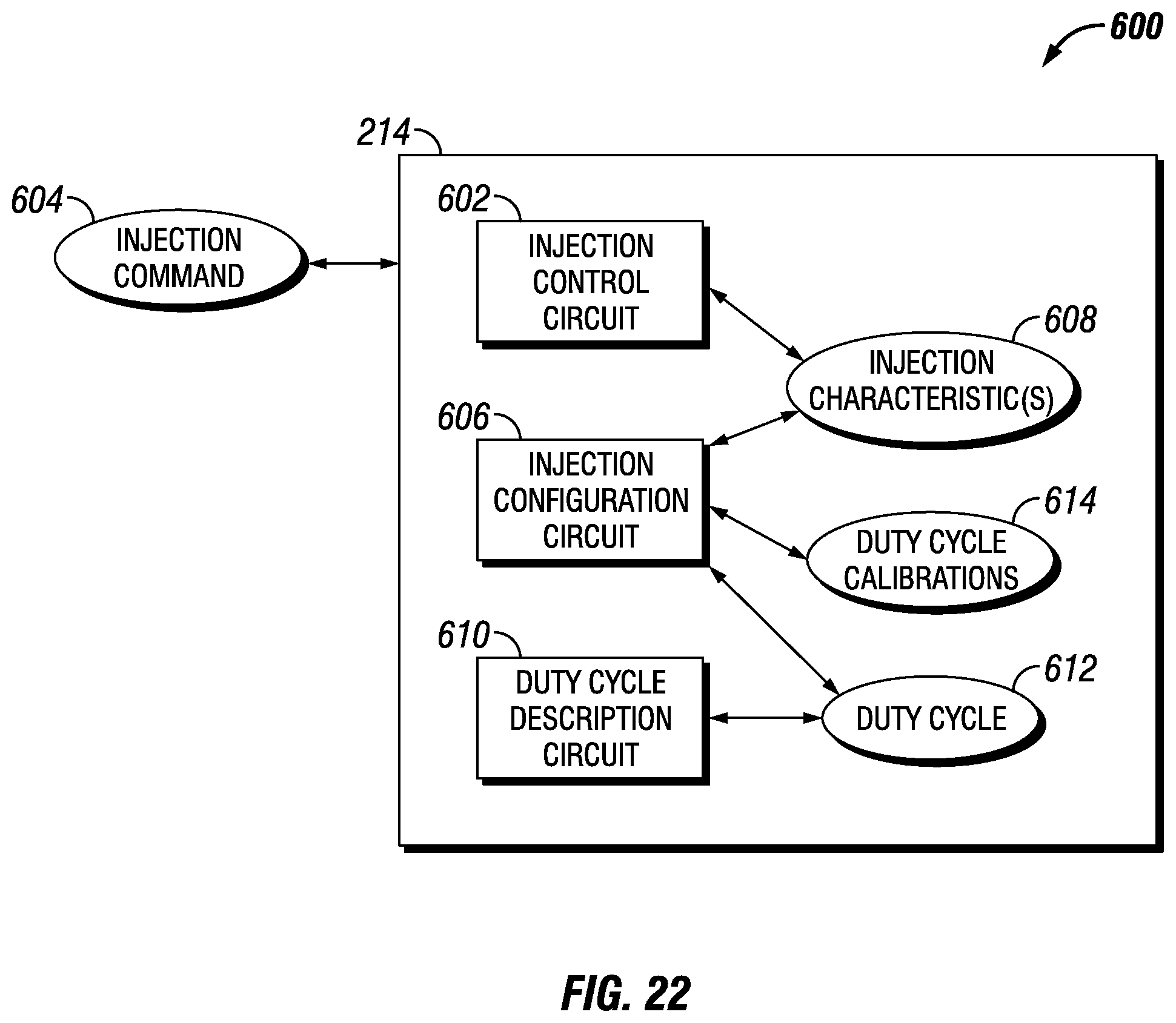
D00016

D00017

D00018

D00019

D00020

D00021

D00022

D00023

D00024

D00025

D00026

D00027

D00028

D00029
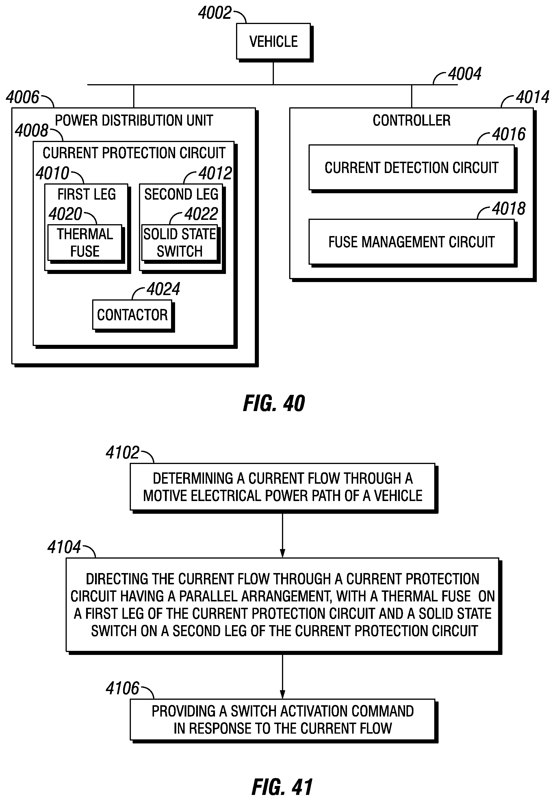
D00030

D00031

D00032

D00033

D00034

D00035

D00036

D00037

D00038

D00039

D00040

D00041

D00042

D00043
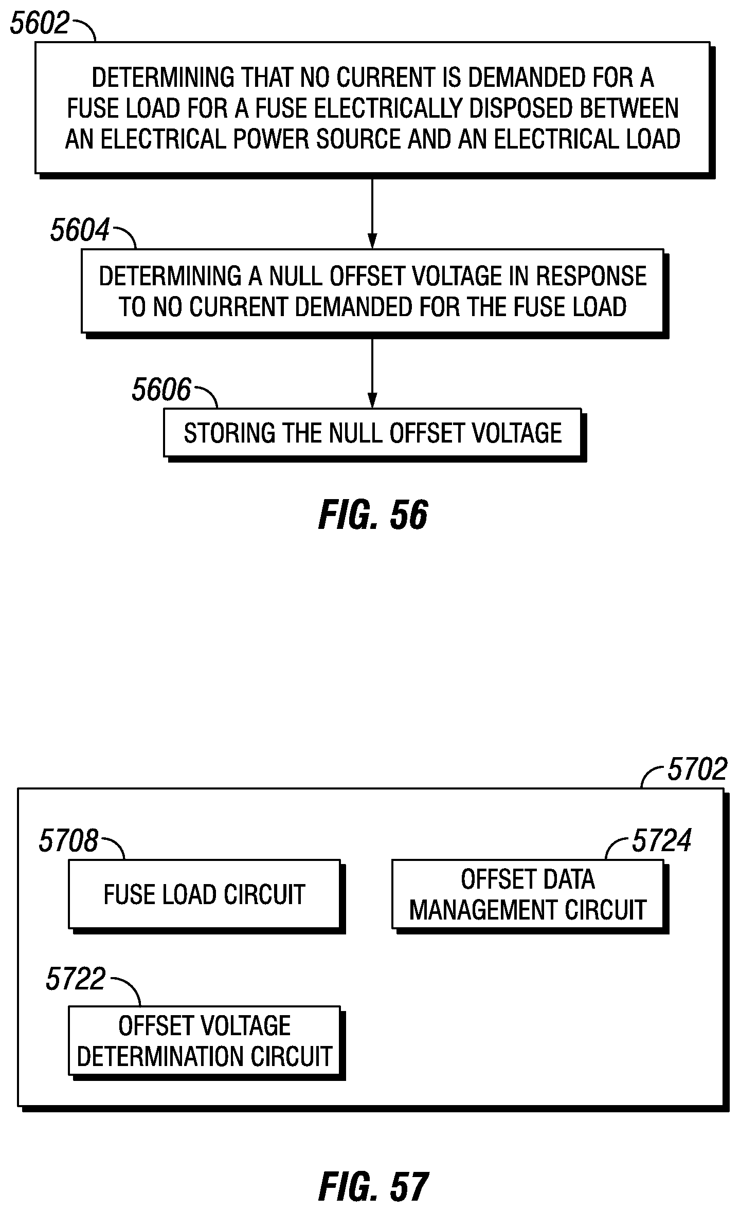
D00044

D00045

D00046

D00047

D00048

XML
uspto.report is an independent third-party trademark research tool that is not affiliated, endorsed, or sponsored by the United States Patent and Trademark Office (USPTO) or any other governmental organization. The information provided by uspto.report is based on publicly available data at the time of writing and is intended for informational purposes only.
While we strive to provide accurate and up-to-date information, we do not guarantee the accuracy, completeness, reliability, or suitability of the information displayed on this site. The use of this site is at your own risk. Any reliance you place on such information is therefore strictly at your own risk.
All official trademark data, including owner information, should be verified by visiting the official USPTO website at www.uspto.gov. This site is not intended to replace professional legal advice and should not be used as a substitute for consulting with a legal professional who is knowledgeable about trademark law.