Absorption Liquid Regeneration Device, Co2 Recovery Device Including The Same, And Absorption Liquid Regeneration Method
Miyamoto; Osamu ; et al.
U.S. patent application number 16/156017 was filed with the patent office on 2020-04-16 for absorption liquid regeneration device, co2 recovery device including the same, and absorption liquid regeneration method. This patent application is currently assigned to Mitsubishi Heavy Industries Engineering, Ltd.. The applicant listed for this patent is Mitsubishi Heavy Industries Engineering, Ltd.. Invention is credited to Takashi Kamijo, Osamu Miyamoto, Tatsuya Tsujiuchi.
| Application Number | 20200114305 16/156017 |
| Document ID | / |
| Family ID | 70162136 |
| Filed Date | 2020-04-16 |


| United States Patent Application | 20200114305 |
| Kind Code | A1 |
| Miyamoto; Osamu ; et al. | April 16, 2020 |
ABSORPTION LIQUID REGENERATION DEVICE, CO2 RECOVERY DEVICE INCLUDING THE SAME, AND ABSORPTION LIQUID REGENERATION METHOD
Abstract
An absorption liquid regeneration apparatus includes: a regeneration tower for regenerating a CO.sub.2 absorption liquid; a reflux water drum configured to separate released gas from the regeneration tower into CO.sub.2 gas and condensed water, and return the condensed water to the regeneration tower; and a cleaning part installed in a gas-phase part of the reflux water drum or in a CO.sub.2 flow passage through which the CO.sub.2 gas having flowed from the gas-phase part flows, and configured to remove a CO.sub.2 absorption agent contained in the CO.sub.2 gas by using a cleaning liquid. The cleaning liquid has a lower concentration of the CO.sub.2 absorption agent than the condensed water stored in a liquid-phase part of the reflux water drum.
| Inventors: | Miyamoto; Osamu; (Houston, TX) ; Kamijo; Takashi; (Kanagawa, JP) ; Tsujiuchi; Tatsuya; (Tokyo, JP) | ||||||||||
| Applicant: |
|
||||||||||
|---|---|---|---|---|---|---|---|---|---|---|---|
| Assignee: | Mitsubishi Heavy Industries
Engineering, Ltd. Kanagawa JP |
||||||||||
| Family ID: | 70162136 | ||||||||||
| Appl. No.: | 16/156017 | ||||||||||
| Filed: | October 10, 2018 |
| Current U.S. Class: | 1/1 |
| Current CPC Class: | B01D 53/78 20130101; B01D 53/1425 20130101; B01D 2256/22 20130101; B01D 53/265 20130101; B01D 2252/20489 20130101; B01D 53/1475 20130101; B01D 53/62 20130101; B01D 2257/504 20130101; B01D 2252/20405 20130101; B01D 2252/20484 20130101; B01D 53/1418 20130101; B01D 2251/306 20130101; B01D 2251/604 20130101; B01D 2251/404 20130101; B01D 2251/304 20130101; B01D 53/96 20130101 |
| International Class: | B01D 53/14 20060101 B01D053/14; B01D 53/26 20060101 B01D053/26 |
Claims
1. An absorption liquid regeneration apparatus, comprising: a regeneration tower for regenerating a CO.sub.2 absorption liquid; a reflux water drum configured to separate released gas from the regeneration tower into CO.sub.2 gas and condensed water, and return the condensed water to the regeneration tower; and a cleaning part installed in a gas-phase part of the reflux water drum or in a CO.sub.2 flow passage at the downstream of the gas-phase part of the reflux water drum, and configured to remove a CO.sub.2 absorption agent contained in the CO.sub.2 gas by using a cleaning liquid, wherein the cleaning liquid has a lower concentration of the CO.sub.2 absorption agent than the condensed water stored in a liquid-phase part of the reflux water drum.
2. The absorption liquid regeneration apparatus according to claim 1, wherein the cleaning part is installed in the gas-phase part of the reflux water drum, and wherein the absorption liquid regeneration apparatus further comprises a cleaning liquid supply part configured to supply the cleaning part with the cleaning liquid, in the gas-phase part of the reflux water drum.
3. The absorption liquid regeneration apparatus according to claim 2, further comprising: a tray installed below the cleaning part in the gas-phase part of the reflux water drum, and configured to be capable of storing the cleaning liquid from the cleaning part; and a circulation line for circulating the cleaning liquid stored in the tray to the cleaning liquid supply part.
4. The absorption liquid regeneration apparatus according to claim 1, further comprising a cleaning drum installed in the CO.sub.2 flow passage separately from the reflux water drum, wherein the cleaning part is installed above a liquid pool part at the bottom of the cleaning drum, and wherein the absorption liquid regeneration apparatus further comprises a cleaning liquid supply part configured to supply the cleaning liquid to the cleaning part of the cleaning drum.
5. The absorption liquid regeneration apparatus according to claim 4, further comprising a circulation line for circulating the cleaning liquid stored in the liquid pool part to the cleaning liquid supply part.
6. The absorption liquid regeneration apparatus according to claim 1, further comprising: a compressor, installed in the CO.sub.2 flow passage, for compressing the CO.sub.2 gas; and a first cleaning liquid line configured to supply compressor condensed water from the compressor as the cleaning liquid toward the cleaning part.
7. The absorption liquid regeneration apparatus according to claim 6, further comprising a compressor condensed water drum, installed at the downstream of the compressor in the CO.sub.2 flow passage, for storing the compressor condensed water separated from the CO.sub.2 gas, wherein the first cleaning liquid line is configured to supply the compressor condensed water in the compressor condensed water drum as the cleaning liquid toward the cleaning part.
8. The absorption liquid regeneration apparatus according to claim 1, further comprising a second cleaning liquid line configured to supply pure water as the cleaning liquid toward the cleaning part.
9. The absorption liquid regeneration apparatus according to claim 6, further comprising: a second cleaning liquid line configured to supply pure water as the cleaning liquid toward the cleaning part; and a line switching part configured to be capable of selecting a supply line of the cleaning liquid, so that the cleaning liquid from at least one of the first cleaning liquid line or the second cleaning liquid line is supplied to the cleaning part.
10. A CO.sub.2 recovery apparatus, comprising: an absorption tower configured to remove the CO.sub.2 gas by bringing the CO.sub.2 absorption liquid and exhaust gas into contact with each other; and the absorption liquid regeneration apparatus according to claim 1.
11. An absorption liquid regeneration method, comprising: regenerating a CO.sub.2 absorption liquid in a regeneration tower; supplying released gas from the regeneration tower to a reflux water drum and separating the released gas into CO.sub.2 gas and condensed water in the reflux water drum; and removing a CO.sub.2 absorption agent contained in the CO.sub.2 gas by contacting the CO.sub.2 gas with a cleaning liquid, in a gas-phase part of the reflux water drum or a cleaning part installed in a CO.sub.2 flow passage at the downstream of the gas-phase part, wherein the cleaning liquid has a lower concentration of the CO.sub.2 absorption agent than the condensed water stored in a liquid-phase part of the reflux water drum.
12. The absorption liquid regeneration method according to claim 1, wherein the cleaning part is installed in the gas-phase part of the reflux water drum, and wherein the method further comprises supplying the cleaning liquid to the cleaning part from a cleaning liquid supply part positioned above the cleaning part in the gas-phase part of the reflux water drum.
13. The absorption liquid regeneration method according to claim 11, further comprising: storing the cleaning liquid from the cleaning part in a tray installed below the cleaning part in the gas-phase part of the reflux water drum; and circulating the cleaning liquid stored in the tray to the cleaning liquid supply part.
14. The absorption liquid regeneration method according to claim 11, further comprising: compressing the CO.sub.2 gas by using a compressor installed in the CO.sub.2 flow passage; storing water separated from the CO.sub.2 gas as compressor condensed water, by using a compressor condensed water drum installed at the downstream of the compressor in the CO.sub.2 flow passage; and supplying the compressor condensed water inside the compressor condensed water drum to the cleaning part as the cleaning liquid, via a first cleaning liquid line.
15. The absorption liquid regeneration method according to claim 14, further comprising: supplying pure water as the cleaning liquid toward the cleaning part via a second cleaning liquid; and selecting a supply line of the cleaning liquid so that the cleaning liquid from at least one of the first cleaning liquid line or the second cleaning liquid line is supplied to the cleaning part.
Description
TECHNICAL FIELD
[0001] The present disclosure relates to an absorption liquid regeneration apparatus, a CO.sub.2 recovery apparatus including the same, and an absorption liquid regeneration method.
BACKGROUND ART
[0002] In recent years, vigorously studied is a method of recovering CO.sub.2 in exhaust gas through gas-liquid contact between the exhaust gas and a CO.sub.2 absorption liquid in a CO.sub.2 recovery apparatus. The CO.sub.2 absorption liquid after having absorbed CO.sub.2 is supplied to an absorption liquid regeneration apparatus, and is regenerated so as to be reusable as a CO.sub.2 absorption liquid.
[0003] For instance, Patent Document 1 describes a CO.sub.2 recovery system where a CO.sub.2 absorption liquid after having absorbed CO.sub.2 in exhaust gas in an absorption tower is regenerated.
[0004] Specifically, in the CO.sub.2 recovery system described in Patent Document 1, the CO.sub.2 absorption liquid supplied from the absorption tower to a regeneration tower is heated by steam in the regeneration tower, and thereby releases gas containing CO.sub.2, thus being regenerated. The released gas is separated into CO.sub.2 gas and reflux water in a reflux water drum. The CO.sub.2 gas released from the reflux water drum is supplied to a separator via a compressor and a cooler. In the separator, the CO.sub.2 gas is separated into CO.sub.2 gas and condensed water containing a small amount of CO.sub.2 absorption agent, of which the condensed water is supplied to the bottom section of the regeneration tower. Accordingly, leakage of the CO.sub.2 absorption liquid outside the system is suppressed, which makes it possible to regenerate the CO.sub.2 absorption liquid effectively.
CITATION LIST
Patent Literature
[0005] Patent Document 1: U.S. Pat. No. 9,050,555B
SUMMARY
[0006] However, in the CO.sub.2 recovery system in Patent Document 1, the gas-phase section of the reflux water drum contains the CO.sub.2 absorption agent corresponding to the steam pressure, and thus an extremely small amount of CO.sub.2 absorption agent exists in the gas phase also at the downstream of the flux water drum. Thus, in some cases, it may be difficult to maintain the concentration of the CO.sub.2 absorption agent in product CO.sub.2 that is finally obtained from the CO.sub.2 recovery system to be not greater than a standard value.
[0007] Thus, in view of the above, an object of some embodiments of the present invention is to provide an absorption liquid regeneration apparatus and an absorption liquid regeneration method capable of effectively suppressing leakage of the CO.sub.2 absorption agent outside the system.
[0008] (1) According to at least one embodiment of the present invention, an absorption liquid regeneration apparatus includes: a regeneration tower for regenerating a CO.sub.2 absorption liquid; a reflux water drum configured to separate released gas from the regeneration tower into CO.sub.2 gas and condensed water, and return the condensed water to the regeneration tower; and a cleaning part installed in a gas-phase part of the reflux water drum or in a CO.sub.2 flow passage through which the CO.sub.2 gas having flowed from the gas-phase part flows, and configured to remove a CO.sub.2 absorption agent contained in the CO.sub.2 gas by using a cleaning liquid. The cleaning liquid has a lower concentration of the CO.sub.2 absorption agent than the condensed water stored in a liquid-phase part of the reflux water drum.
[0009] With the above configuration (1), a cleaning part is provided, which cleans CO.sub.2 gas separated in the reflux water drum by using a cleaning liquid and remove a CO.sub.2 absorption agent. Further, the cleaning liquid used in the cleaning part has a lower concentration of CO.sub.2 absorption agent compared to the condensed water stored in the reflux water drum. Thus, it is possible to dissolve the CO.sub.2 absorption agent contained in CO.sub.2 gas effectively in the cleaning liquid. Accordingly, it is possible to suppress leakage of the CO.sub.2 gas absorption agent outside the system effectively. Further, it is possible to reduce the concentration of the CO.sub.2 absorption agent in the final product CO.sub.2.
[0010] (2) In some embodiments, in the above configuration (1), the cleaning part is installed in the gas-phase part of the reflux water drum, and the absorption liquid regeneration apparatus further includes a cleaning liquid supply part configured to supply the cleaning part with the cleaning liquid, in the gas-phase part of the reflux water drum.
[0011] With the above configuration (2), it is possible to bring CO.sub.2 and a cleaning liquid into gas-liquid contact with each other in the cleaning part. Further, by providing the cleaning part in the reflux water drum, it is possible to provide the cleaning part while saving space. Accordingly, it is possible to suppress leakage of the CO.sub.2 absorption agent outside the system effectively while saving space on the basis of the principle described in the above (1).
[0012] (3) In some embodiments, in the above configuration (2), the absorption liquid regeneration apparatus further includes: a tray installed below the cleaning part in the gas-phase part of the reflux water drum, and configured to be capable of storing the cleaning liquid from the cleaning part; and a circulation line for circulating the cleaning liquid stored in the tray to the cleaning liquid supply part.
[0013] With the above configuration (3), it is possible to receive the cleaning liquid used in the cleaning part with a tray installed below the cleaning part. Further, the cleaning liquid stored in the tray is circulated to the cleaning-liquid supply part through the circulation line, and reused. As a result, it is possible to suppress leakage of the CO.sub.2 absorption agent outside the system effectively, on the basis of the principle described in the above (1), while effectively re-utilizing the cleaning liquid.
[0014] (4) In some embodiments, in the above configuration (1), the absorption liquid regeneration apparatus further includes a cleaning drum installed in the CO.sub.2 flow passage separately from the reflux water drum. The cleaning part is installed above a liquid pool part at the bottom of the cleaning drum, and the absorption liquid regeneration apparatus further comprises a cleaning liquid supply part configured to supply the cleaning liquid to the cleaning part of the cleaning drum.
[0015] With the above configuration (4), by providing the cleaning part in the cleaning drum provided separately from the reflux water drum, it is possible to ensure a sufficient capacity for the cleaning part to remove the remaining CO.sub.2 gas absorption agent through gas-liquid contact between the CO.sub.2 gas and the cleaning liquid. Accordingly, it is possible to suppress leakage of the CO.sub.2 absorption agent outside the system even more effectively on the basis of the principle described in the above (1).
[0016] (5) In some embodiments, in the above configuration (4), the absorption liquid regeneration apparatus further includes a circulation line for circulating the cleaning liquid stored in the liquid pool part to the cleaning liquid supply part.
[0017] With the above configuration (5), it is possible to circulate the cleaning liquid stored in the liquid storage part to the cleaning-liquid supply part through the circulation line, and re-utilize the cleaning liquid to clean CO.sub.2 gas in the cleaning part. As a result, it is possible to suppress leakage of the CO.sub.2 absorption agent outside the system effectively, on the basis of the principle described in the above (1), while effectively re-utilizing the cleaning liquid.
[0018] (6) In some embodiments, in any one of the above configurations (1) to (5), the absorption liquid regeneration apparatus further includes: a compressor, installed in the CO.sub.2 flow passage, for compressing the CO.sub.2 gas; and a first cleaning liquid line configured to supply compressor condensed water from the compressor as the cleaning liquid toward the cleaning part.
[0019] With the above configuration (6), compressor condensed water is used as a cleaning liquid. As a result, it is possible to suppress leakage of the CO.sub.2 absorption agent outside the system effectively while effectively using the resource inside the system of the absorption liquid regeneration apparatus, on the basis of the principle described in the above (1).
[0020] (7) In some embodiments, in the above configuration (6), the absorption liquid regeneration apparatus further includes a compressor condensed water drum, installed at the downstream of the compressor in the CO.sub.2 flow passage, for storing the compressor condensed water separated from the CO.sub.2 gas. The first cleaning liquid line is configured to supply the compressor condensed water in the compressor condensed water drum, as the cleaning liquid, toward the cleaning part.
[0021] With the above configuration (7), compressor condensed water stored in the compressor condensed water drum is used as a cleaning liquid. As a result, it is possible to suppress leakage of the CO.sub.2 absorption agent outside the system effectively while effectively using the resource inside the system of the absorption liquid regeneration apparatus, on the basis of the principle described in the above (1).
[0022] (8) In some embodiments, in any one of the above configurations (1) to (7), the absorption liquid regeneration apparatus further includes a second cleaning liquid line configured to supply pure water as the cleaning liquid toward the cleaning part.
[0023] With the above configuration (8), pure water is used as a cleaning liquid, and thus it is possible to use a cleaning liquid not containing a CO.sub.2 absorption agent for cleaning. Accordingly, it is possible to suppress leakage of the CO.sub.2 absorption agent outside the system even more effectively on the basis of the principle described in the above (1).
[0024] Furthermore, it is possible to reduce the concentration of the CO.sub.2 absorption agent in the final product CO.sub.2 effectively. Thus, the above configuration (8) is effective, for instance, in a case where there is a strict standard for the concentration of the CO.sub.2 absorption agent in the product CO.sub.2.
[0025] (9) In some embodiments, in the above configuration (6) or (7), the absorption liquid regeneration apparatus further includes: a second cleaning liquid line configured to supply pure water as the cleaning liquid toward the cleaning part; and a line switching part configured to be capable of selecting a supply line of the cleaning liquid, so that the cleaning liquid from at least one of the first cleaning liquid line or the second cleaning liquid line is supplied to the cleaning part.
[0026] With the above configuration (9), with the line switching part, it is possible to select a cleaning liquid to be used, from the compressor condensed water, the pure water, or water mixture of the above.
[0027] For instance, in a case where the compressor condensed water is suitable for cleaning, it is possible to clean CO.sub.2 gas efficiently by using the resource in the system of the absorption liquid regeneration apparatus by using the compressor condensed water in priority. Meanwhile, in a case where the pure water is suitable for cleaning, it is possible to reduce the concentration of the remaining CO.sub.2 gas absorption agent in the product CO.sub.2 further, by using the pure water in priority. Furthermore, in a case where the compressor condensed water has an increased concentration of the CO.sub.2 absorption agent and is no longer suitable for cleaning of the CO.sub.2 gas, pure water can be used as the cleaning liquid.
[0028] Accordingly, by selecting the cleaning liquid to be used suitably with the line switching part, it is possible to suppress leakage of the CO.sub.2 absorption agent outside the system effectively while making effective use of the resource inside the system of the absorption liquid regeneration apparatus.
[0029] (10) According to at least one embodiment of the present invention, a CO.sub.2 recovery apparatus includes: an absorption tower configured to remove the CO.sub.2 gas by bringing the CO.sub.2 absorption liquid and exhaust gas into contact with each other; and the absorption liquid regeneration apparatus according to any one of the above (1) to (9).
[0030] With the above configuration (10), it is possible to suppress leakage of the CO.sub.2 absorption agent outside the system on the basis of the principle described in the above (1).
[0031] (11) According to at least one embodiment of the present invention, an absorption liquid regeneration method includes: regenerating a CO.sub.2 absorption liquid in a regeneration tower; supplying released gas from the regeneration tower to a reflux water drum and separating the released gas into CO.sub.2 gas and condensed water in the reflux water drum; and removing a CO.sub.2 absorption agent contained in the CO.sub.2 gas by contacting the CO.sub.2 gas with a cleaning liquid, in a gas-phase part of the reflux water drum or a cleaning part installed in a CO.sub.2 flow passage at the downstream of the gas-phase part. The cleaning liquid has a lower concentration of the CO.sub.2 absorption agent than the condensed water stored in a liquid-phase part of the reflux water drum.
[0032] According to the above method (11), provided is a step of cleaning CO.sub.2 gas separated in the reflux water drum by using a cleaning liquid and removing a CO.sub.2 absorption agent. Further, the cleaning liquid used in the cleaning part has a lower concentration of CO.sub.2 absorption agent compared to the condensed water stored in the reflux water drum. Thus, it is possible to dissolve the CO.sub.2 absorption agent contained in CO.sub.2 gas effectively in the cleaning liquid. Accordingly, it is possible to suppress leakage of the CO.sub.2 gas absorption agent outside the system effectively. Further, it is possible to reduce the concentration of the CO.sub.2 absorption agent in the final product CO.sub.2.
[0033] (12) In some embodiments, in the above method (11), the cleaning part is installed in the gas-phase part of the reflux water drum, and the method further includes supplying the cleaning liquid to the cleaning part from a cleaning liquid supply part positioned above the cleaning part in the gas-phase part of the reflux water drum.
[0034] According to the above method (12), with the cleaning-liquid supply part provided above the cleaning part, it is possible to bring CO.sub.2 and a cleaning liquid into gas-liquid contact with each other in the cleaning part. Further, by providing the cleaning part in the reflux water drum, it is possible to provide the cleaning part while saving space. Accordingly, it is possible to suppress leakage of the CO.sub.2 absorption agent outside the system effectively while saving space on the basis of the principle described in the above (11).
[0035] (13) In some embodiments, the above method (12) further includes: storing the cleaning liquid from the cleaning part in a tray installed below the cleaning part in the gas-phase part of the reflux water drum; and circulating the cleaning liquid stored in the tray to the cleaning liquid supply part.
[0036] With the above configuration (13), it is possible to receive the cleaning liquid used in the cleaning part with a tray installed below the cleaning part. Further, the cleaning liquid stored in the tray is circulated to the cleaning-liquid supply part through the circulation line, and reused. As a result, it is possible to suppress leakage of the CO.sub.2 absorption agent outside the system effectively, on the basis of the principle described in the above (11), while effectively re-utilizing the cleaning liquid.
[0037] (14) In some embodiments, any one of the above methods (11) to (13) further includes: compressing the CO.sub.2 gas by using a compressor installed in the CO.sub.2 flow passage; storing water separated from the CO.sub.2 gas as compressor condensed water, by using a compressor condensed water drum installed at the downstream of the compressor in the CO.sub.2 flow passage; and supplying the compressor condensed water inside the compressor condensed water drum to the cleaning part as the cleaning liquid, via a first cleaning liquid line.
[0038] With the above configuration (14), compressor condensed water in the compressor condensed water drum is used as a cleaning liquid. As a result, it is possible to suppress leakage of the CO.sub.2 absorption agent outside the system effectively while effectively using the resource inside the system of the absorption liquid regeneration apparatus, on the basis of the principle described in the above (11).
[0039] (15) In some embodiments, the above method (14) further includes supplying pure water as the cleaning liquid toward the cleaning part via a second cleaning liquid; and selecting a supply line of the cleaning liquid so that the cleaning liquid from at least one of the first cleaning liquid line or the second cleaning liquid line is supplied to the cleaning part.
[0040] With the above configuration (15), with the line switching part, it is possible to select a cleaning liquid to be used, from the compressor condensed water, the pure water, or water mixture of the above.
[0041] For instance, in a case where the compressor condensed water is suitable for cleaning, it is possible to clean CO.sub.2 gas efficiently by using the resource in the system of the absorption liquid regeneration apparatus by using the compressor condensed water in priority. Meanwhile, in a case where the pure water is suitable for cleaning, it is possible to reduce the concentration of the remaining CO.sub.2 gas absorption agent in the product CO.sub.2 further, by using the pure water in priority. Furthermore, in a case where the compressor condensed water has an increased concentration of the CO.sub.2 absorption agent and is no longer suitable for cleaning of the CO.sub.2 gas, the pure water can be used as the cleaning liquid.
[0042] Accordingly, by selecting the cleaning liquid to be used in the line switching part suitably, it is possible to suppress leakage of the CO.sub.2 absorption agent outside the system effectively while making effective use of the resource inside the system of the absorption liquid regeneration apparatus.
[0043] According to some embodiments of the present invention, it is possible to suppress leakage of the CO.sub.2 gas absorption agent outside the system effectively.
BRIEF DESCRIPTION OF DRAWINGS
[0044] FIG. 1 is a schematic diagram showing the configuration of a CO.sub.2 recovery apparatus according to an embodiment of the present invention, where a reflux water drum includes a cleaning part.
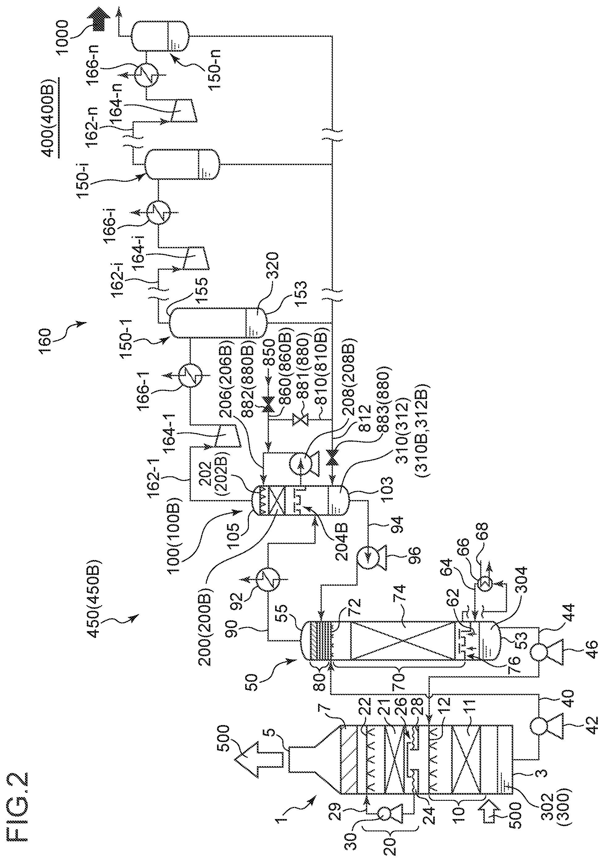
[0045] FIG. 2 is a schematic diagram of a configuration of a CO.sub.2 recovery apparatus according to another embodiment of the present invention, where a reflux water drum includes a cleaning part and a circulation line.
[0046] FIG. 3 is a schematic diagram showing the configuration of a CO.sub.2 recovery apparatus according to an embodiment of the present invention, where a cleaning drum includes a cleaning part.
[0047] FIG. 4 is a schematic diagram of a configuration of a CO.sub.2 recovery apparatus according to another embodiment of the present invention, where a reflux water drum includes a cleaning part and a circulation line.
[0048] FIG. 5 is a schematic diagram showing the configuration of a CO.sub.2 recovery apparatus according to an embodiment of the present invention, where a compressor condensed water drum includes a cleaning part.
[0049] FIG. 6 is an enlarged schematic diagram of a reflux part of a regeneration tower according to an embodiment of the present invention.
DETAILED DESCRIPTION
[0050] Embodiments of the present invention will now be described in detail with reference to the accompanying drawings.
[0051] However, the scope of the present invention is not limited to the following embodiments. It is intended that dimensions, materials, shapes, relative positions and the like of components described in the embodiments shall be interpreted as illustrative only and not intended to limit the scope of the present invention.
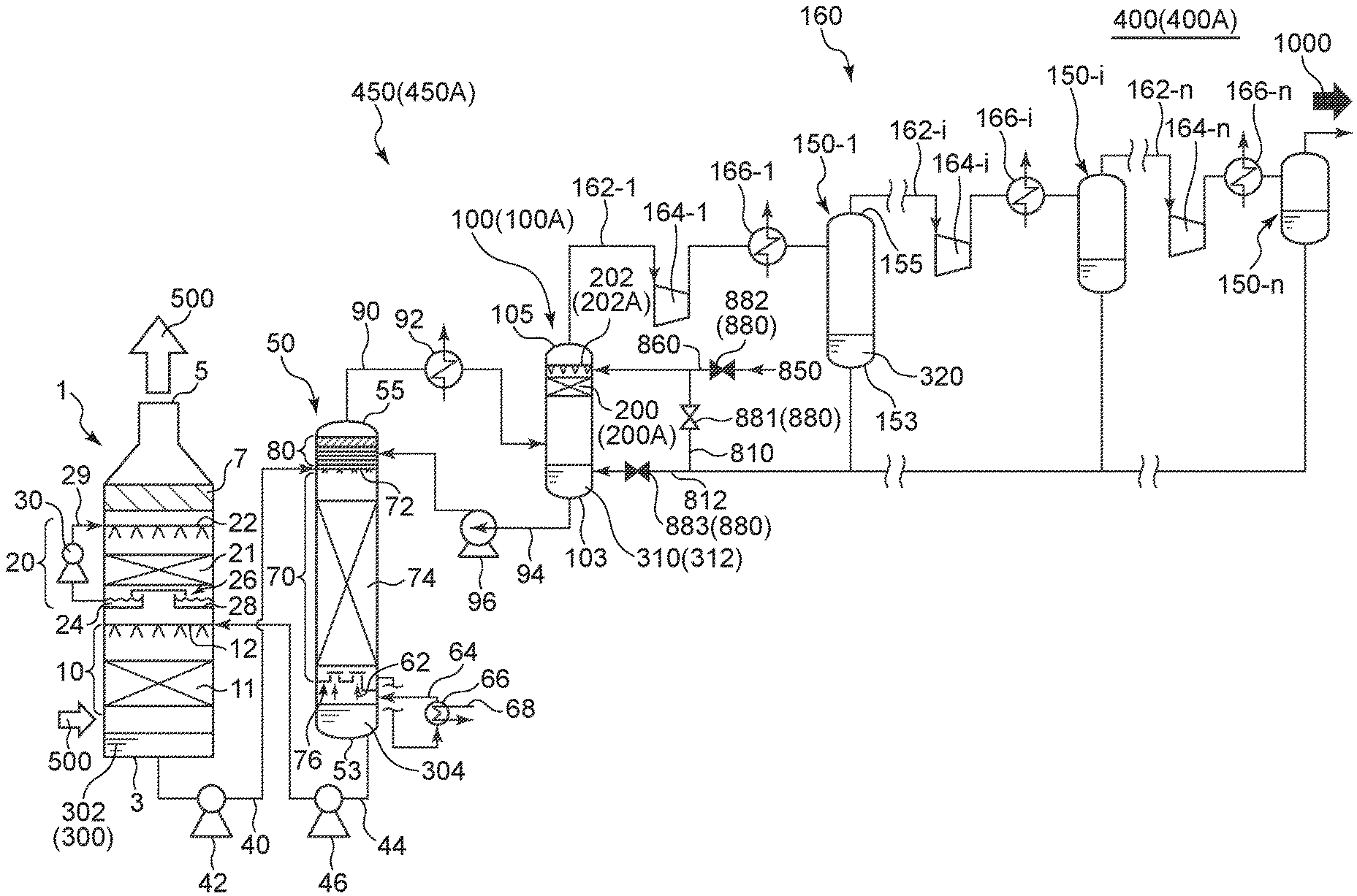
[0052] FIG. 1 is a schematic diagram showing the configuration of a CO.sub.2 recovery apparatus 400A according to an embodiment of the present invention, where a reflux water drum 100A includes a cleaning part 200A. FIG. 2 is a schematic diagram of a configuration of a CO.sub.2 recovery apparatus 400B according to another embodiment of the present invention, where a reflux water drum 100B includes a cleaning part 200B and a circulation line 206B. FIG. 3 is a schematic diagram showing the configuration of a CO.sub.2 recovery apparatus 400C according to an embodiment of the present invention, where a cleaning drum 250C includes a cleaning part 200C. FIG. 4 is a schematic diagram of a configuration of a CO.sub.2 recovery apparatus 400D according to another embodiment of the present invention, where a reflux water drum 250D includes a cleaning part 200D and a circulation line 206D. FIG. 5 is a schematic diagram showing the configuration of a CO.sub.2 recovery apparatus 400E according to an embodiment of the present invention, where a compressor condensed water drum 150E includes a cleaning part 200E. FIG. 6 is an enlarged schematic diagram of a reflux part 80 of a regeneration tower 50 according to an embodiment of the present invention.
[0053] In the following description, CO.sub.2 recovery apparatuses 400A, 400B, 400C, 400D, and 400E may be collectively referred to as a CO.sub.2 recovery apparatus 400.
[0054] According to some embodiments of the present invention, as depicted in FIGS. 1 to 5, the CO.sub.2 recovery apparatus 400 includes an absorption tower 1, and an absorption liquid regeneration apparatus 450 for regenerating a CO.sub.2 absorption liquid 300 (rich absorption liquid 302 described below) having absorbed CO.sub.2 gas.
[0055] The CO.sub.2 recovery apparatus 400 has a function to recover CO.sub.2 gas in exhaust gas 500, through gas-liquid contact between exhaust gas 500 discharged from a factory or the like and the CO.sub.2 absorption liquid 300 in the absorption tower 1. The CO.sub.2 absorption liquid 300 (rich absorption liquid 302) having absorbed CO.sub.2 gas is supplied to the absorption liquid regeneration apparatus 450.
[0056] The absorption liquid regeneration apparatus 450 includes a regeneration tower 50 which releases CO.sub.2 gas from the CO.sub.2 absorption liquid 300 having absorbed CO.sub.2 gas (rich absorption liquid 302) and regenerate a CO.sub.2 absorption liquid 300 to be reusable, and a reflux water drum 100 configured to separate the released gas from the regeneration tower 50 into CO.sub.2 gas and condensed water 310, and return the condensed water 310 to the regeneration tower 50.
[0057] The CO.sub.2 gas released from the absorption liquid regeneration apparatus 450 is compressed and cooled, and compressor condensed water 320 is removed from the CO.sub.2 gas in the compressor condensed water drum 150. The CO.sub.2 gas is compressed and cooled repeatedly in a plurality of stages, and the compressor condensed water 320 may be removed in the compressor condensed water drum 150 each time the CO.sub.2 gas is compressed and cooled. The CO.sub.2 gas after undergoing one or more stage of compression and cooling is taken out from the system as product CO.sub.2 1000.
[0058] As depicted in FIGS. 1 to 5, the absorption tower 1 includes an absorption part 10 that absorbs CO.sub.2 gas in the exhaust gas 500, a water washing part 20 that water-washes the exhaust gas 500 from which CO.sub.2 gas is removed, and a mist eliminator 7 that removes mist in the exhaust gas 500.
[0059] The exhaust gas 500 flows into the absorption tower 1 from below the absorption part 10, at the side of the tower bottom part 3 of the absorption tower 1. The exhaust gas 500 flows upward through the absorption tower 1 from the side of the tower bottom part 3 of the absorption tower 1, and flows into the absorption part 10.
[0060] The absorption part 10 includes a gas-liquid contact part 11 for bringing exhaust gas 500 into contact with the CO.sub.2 absorption liquid 300 containing a CO.sub.2 absorption agent, and a CO.sub.2 absorption liquid supply part 12 installed above the gas-liquid contact part 11. The exhaust gas 500 performs counter-current contact with the CO.sub.2 absorption liquid 300 supplied from above by the CO.sub.2 absorption liquid supply part 12, in the gas-liquid contact part 11.
[0061] The gas-liquid contact part 11 is not particularly limited as long as it can promote gas-liquid contact between the CO.sub.2 absorption liquid 300 and the exhaust gas 500. For instance, the gas-liquid contact part 11 may be formed by a packed layer packed with a packing material of a non-limited material, or may be formed by one or more stages of trays.
[0062] The type of the CO.sub.2 absorption agent contained in the CO.sub.2 absorption liquid 300 is not particularly limited. For instance, alkanolamines such as monoethanolamine and diethanolamine, or various alkaline aqueous solutions other than amines such as sodium hydroxide, potassium hydroxide and calcium hydroxide can be used the CO.sub.2 absorption liquid 300.
[0063] Due to the reaction in the gas-liquid contact part 11, the CO.sub.2 gas in the exhaust gas 500 is absorbed by the CO.sub.2 absorption liquid 300. For instance, in a case where an amine is used as the CO.sub.2 absorption agent, the absorption reaction of CO.sub.2 gas is represented by a reaction expression R-NH.sub.2+H.sub.2O+CO.sub.2.fwdarw.R--NH.sub.3HCO.sub.3. As a result of the absorption reaction, most part of CO.sub.2 gas is removed from the exhaust gas 500 flowing upward through the absorption tower 1 via the absorption part 10.
[0064] The CO.sub.2 absorption liquid 300 having reacted with the CO.sub.2 gas in the exhaust gas 500 in the gas-liquid contact part 11 falls onto the tower bottom part 3 of the absorption tower 1, and is stored in the tower bottom part 3. The CO.sub.2 absorption liquid 300 stored in the tower bottom part 3 of the absorption tower 1 is referred to as a rich absorption liquid 302.
[0065] The rich absorption liquid 302 contains a great amount of CO.sub.2 gas that is absorbed from the exhaust gas 500.
[0066] Meanwhile, exhaust gas 500 deprived of CO.sub.2 gas through contact with the CO.sub.2 absorption liquid 300 in the gas-liquid contact part 11 flows further upward through the absorption tower 1 toward the tower top part 5.
[0067] The exhaust gas 500 after having passed through the gas-liquid contact part 11 contains a CO.sub.2 absorption agent, from the relationship of the saturated steam pressure at the temperature of the exhaust gas 500. Thus, to recover the CO.sub.2 absorption agent contained in the exhaust gas 500 after passing through the gas-liquid contact part 11, the exhaust gas 500 may be water-washed by the water washing part 20 installed above the absorption part 10.
[0068] The water washing part 20 includes a gas-liquid contact part 21, a cleaning-water supply part 22 for supplying cleaning water 24 from above the gas-liquid contact part 21, and a chimney tray 26 installed below the gas-liquid contact part 21.
[0069] The exhaust gas 500 flows upward to the gas-liquid contact part 21 via the opening portion of the chimney tray 26, after passing through the absorption part 10. Further, while the chimney tray 26 is configured to permit a gas to pass through from the bottom toward the top via the opening portion, a liquid is not let through from the top toward the bottom.
[0070] In the gas-liquid contact part 21, the exhaust gas 500 having flown upward makes gas-liquid contact with the cleaning water 24 supplied from the cleaning-water supply part 22, and thereby the CO.sub.2 absorption agent in the exhaust gas 500 dissolves in the cleaning water 24.
[0071] The water washing part 20 may further include a cleaning-water circulation line 29 for circulating the cleaning water 24, and a cleaning-water circulation pump 30 installed in the cleaning-water circulation line 29.
[0072] The cleaning water 24 after cleaning the exhaust gas 500 falls from the gas-liquid contact part 21, and is stored in the liquid storage part 28 of the chimney tray 26. The cleaning water 24 stored in the liquid storage part 28 is circulated by the cleaning-water circulation pump 30 via the cleaning-water circulation line 29, and is supplied again toward the gas-liquid contact part 21 from the cleaning-water supply part 22.
[0073] Further, while the absorption tower 1 includes a single stage of water washing part 20 in FIGS. 1 to 5, the absorption tower 1 may include a plurality of stages of water washing parts 20.
[0074] The exhaust gas 500 deprived of the CO.sub.2 absorption agent in the water washing part 20 having the above configuration further flows upward through the absorption tower 1 toward the tower top part 5, and reaches the mist eliminator 7. The mist eliminator 7 captures mist in the exhaust gas 500.
[0075] The exhaust gas 500 deprived of mist by the mist eliminator 7 is discharged outside from the tower top part 5 of the absorption tower 1.
[0076] Next, described below in detail is the configuration of the absorption liquid regeneration apparatus 450 for regenerating the CO.sub.2 absorption liquid 300 (rich absorption liquid 302) having absorbed CO.sub.2 from the exhaust gas 500, in the absorption tower 1 having the above configuration.
[0077] The rich absorption liquid 302 is supplied to the rich absorption liquid supply part 72 installed on the side of the tower top part 55 of the regeneration tower 50, from the tower bottom part 3 of the absorption tower 1, by the rich absorption liquid circulation pump 42 installed in the rich absorption liquid supply line 40.
[0078] As depicted in FIGS. 1 to 5, the regeneration tower 50 includes a release part 70 that releases CO.sub.2 gas from the rich absorption liquid 302 and a reflux part 80 which cleans the released CO.sub.2 gas with the reflux water 312.
[0079] The release part 70 includes a rich absorption liquid supply part 72 for supplying the rich absorption liquid 302, and a charge part 74 which is installed below the rich absorption liquid supply part 72.
[0080] The rich absorption liquid 302 is supplied to the charge part 74 from above by the rich absorption liquid supply part 72.
[0081] The rich absorption liquid 302 is heated by the saturated steam 62 described below, in the charge part 74, releases CO.sub.2 gas, and becomes a lean absorption liquid 304 which contains a relatively low rate of CO.sub.2.
[0082] Below the charge part 74, installed is a chimney tray 76 for receiving the lean absorption liquid 304.
[0083] The lean absorption liquid 304 received by the chimney tray 76 is supplied through a re-boiler line 64, to a regeneration heater (re-boiler) 66 installed in the re-boiler line 64.
[0084] The regeneration heater 66 includes a line 68 for supplying a heating medium (e.g. saturated steam) to the regeneration heater 66. The lean absorption liquid 304 heated through heat exchange with the heating medium in the regeneration heater 66 at least partially changes in phase to the saturated steam 62, and is supplied to the lower section of the chimney tray 76 through the re-boiler line 64 in a gas-liquid phase mixed state. Accordingly, the saturated steam 62 produced by the regeneration heater 66 flows upward through the regeneration tower 50 to the charge part 74, via the chimney tray 76.
[0085] On the other hand, the lean absorption liquid 304 supplied to the lower section of the chimney tray 76 via the re-boiler line 64 (lean absorption liquid 304 that has not changed in phase in the regeneration heater 66) is stored in the tower bottom part 53 of the regeneration tower 50.
[0086] The lean absorption liquid 304 stored in the tower bottom part 53 is taken out from the tower bottom part 53 of the regeneration tower 50 through a lean liquid feeding line 44, and is fed to the CO.sub.2 absorption liquid supply part 12 of the absorption tower 1 by the lean liquid feeding pump 46. The lean absorption liquid 304 returned to the CO.sub.2 absorption liquid supply part 12 of the absorption tower 1 is reused as the above described CO.sub.2 absorption liquid 300.
[0087] On the other hand, CO.sub.2 gas released from the rich absorption liquid 302 at the release part 70 flows toward the reflux part 80 installed above the release part 70 in the regeneration tower 50.
[0088] As depicted in FIG. 6, the reflux part 80 of the regeneration tower 50 may include a plurality of stages of trays 82a to 82d.
[0089] The reflux water 312 described below flows through the trays 82a to 82d of the reflux part 80.
[0090] As depicted in FIG. 6, the CO.sub.2 gas released at the release part 70 makes gas-liquid contact with the reflux water 312 flowing through the trays 82a to 82d of the reflux part 80 a plurality of times (herein, four times), and thereby the CO.sub.2 absorption agent is removed, and the CO.sub.2 gas is cleaned.
[0091] Further, although four stages of trays 82a to 82d are depicted in FIG. 6, the number of stages of trays is not particularly limited.
[0092] The CO.sub.2 gas after passing through the reflux part 80 is released from the tower top part 55 of the regeneration tower 50, and is supplied to the CO.sub.2 gas line 90.
[0093] The CO.sub.2 gas is cooled by the condenser 92 in the CO.sub.2 gas line 90. Accordingly, water vapor in the CO.sub.2 gas is condensed.
[0094] The CO.sub.2 gas after passing through the condenser 92 is separated into CO.sub.2 gas and condensed water 310 in the reflux water drum 100 installed on the outlet side of the CO.sub.2 gas line 90.
[0095] The condensed water 310 separated by the reflux water drum 100 is stored in the tower bottom part 103 of the reflux water drum 100.
[0096] The condensed water 310 stored in the tower bottom part 103 is sent to the reflux part 80 of the regeneration tower 50 as reflux water 312, via the reflux water feeding line 94. The reflux water 312 is fed by the reflux water circulation pump 96.
[0097] Furthermore, the CO.sub.2 separated by the reflux water drum 100 is released from the tower top part 105 of the reflux water drum 100, and flows toward a post-treatment device 160.
[0098] The post-treatment device 160 includes gas supply lines 162 (the first gas supply line 162-1 to the n-th gas supply line 162-n), compressors 164 (the first compressor 164-1 to the n-th compressor 164-n) installed in the gas supply lines 162 for compressing CO.sub.2 gas, coolers 166 (the first cooler 166-1 to the n-th cooler 166-n) that are installed at the downstream of the compressors 164 in the gas supply lines 162 to cool CO.sub.2 gas, and compressor condensed water drums 150 (the first compressor condensed water drum 150-1 to the n-th compressor condensed water drum 150-n) installed on the outlet side of the gas supply lines 162 to remove moisture from the CO.sub.2 gas.
[0099] N is an integer not less than one.
[0100] The first compressor 164-1 is installed most upstream of the plurality of compressors. The first cooler 166-1 is installed most upstream of the plurality of coolers. The first compressor condensed water drum 150-1 is installed most upstream of the plurality of compressor condensed water drums.
[0101] The CO.sub.2 gas having flown into the post-treatment device 160 is compressed by the compressor 164, and is cooled by the cooler 166. Accordingly, moisture contained in the CO.sub.2 gas is condensed. The step of separating the moisture with the compressor condensed water drum 150 and storing the moisture as compressor condensed water 320 in the tower bottom part 153 of the compressor condensed water drum 150 is repeated n times.
[0102] The CO.sub.2 gas deprived of moisture is released from the tower top part 155 of the compressor condensed water drum 150.
[0103] After repeating compression and cooling of CO.sub.2 gas n times, CO.sub.2 gas is released from the tower top part 155 of the n-th compressor condensed water drum 150-n, and is taken out as product CO.sub.2 1000.
[0104] Described above is the overall configuration of the CO.sub.2 recovery apparatus 400.
[0105] Next, with reference to FIGS. 1 to 5, the configuration of the cleaning part 200 of the CO.sub.2 recovery apparatus 400 according to some embodiments of the present invention will be described.
[0106] As described above, the CO.sub.2 absorption liquid 300 (rich absorption liquid 302) having absorbed CO.sub.2 gas in the absorption tower 1 is regenerated in the regeneration tower 50. At this time, CO.sub.2 gas is released from the rich absorption liquid 302. While the CO.sub.2 gas released from the rich absorption liquid 302 is cleaned in the reflux part 80, it is difficult to recover the CO.sub.2 absorption agent completely in the reflux part 80, and thus the CO.sub.2 contains a small amount of CO.sub.2 absorption agent. The CO.sub.2 gas containing a small amount of CO.sub.2 absorption agent is discharged from the regeneration tower 50, and is separated into CO.sub.2 gas and condensed water 310 in the reflux water drum 100. At this time, a part of the CO.sub.2 absorption agent moves toward the condensed water 310. Another part of the CO.sub.2 absorption agent corresponding to the saturated steam pressure remains in the CO.sub.2 gas at the gas-phase part of the reflux water drum 100.
[0107] Thus, the absorption liquid regeneration apparatus 450 (450A to 450E) according to some embodiments, as depicted in FIGS. 1 to 5, includes a cleaning part 200 (200A to 200E) that removes the remaining CO.sub.2 absorption agent from the CO.sub.2 gas separated in the reflux water drum 100.
[0108] The cleaning part 200 is installed in the gas-phase part of the reflux water drum 100, or in the CO.sub.2 flow passage of CO.sub.2 flowing out from the gas-phase part of the reflux water drum 100.
[0109] In the cleaning part 200, the CO.sub.2 gas absorption agent contained in CO.sub.2 gas is removed through gas-liquid contact between the CO.sub.2 gas and a cleaning liquid. The cleaning liquid may be any liquid that has a lower concentration of CO.sub.2 gas absorption agent compared to the condensed water 310 stored in the gas-phase part of the reflux water drum 100.
[0110] As described above, by cleaning the CO.sub.2 gas by using a cleaning liquid having a relatively low concentration of CO.sub.2 gas absorption agent, it is possible to effectively dissolve, in the cleaning liquid, the CO.sub.2 gas absorption agent corresponding to the saturated steam pressure contained in the CO.sub.2 gas after being separated from the condensed water 310 in the reflux water drum 100. Accordingly, it is possible to suppress leakage of the CO.sub.2 gas absorption agent outside the system effectively.
[0111] The cleaning part 200 for cleaning the CO.sub.2 gas may be installed on various positions as long as it is capable of cleaning CO.sub.2 gas after being separated from the condensed water 310 in the reflux water drum 100.
[0112] For instance, as in the embodiment depicted in FIGS. 1 and 2, the cleaning part 200 (200A, 200B) may be installed in the gas-phase part of the reflux water drum 100 (100A, 100B). In this case, the absorption liquid regeneration apparatus 450 (450A, 450B) may include a cleaning-liquid supply part 202 (202A, 202B) for supplying a cleaning liquid to the cleaning part 200. The cleaning part 200 (200A, 200B) may be formed by the gas-liquid contact part installed below the cleaning-liquid supply part 202. The gas-liquid contact part constituting the cleaning part 200 is not particularly limited as long as it can promote gas-liquid contact. For instance, similarly to the gas-liquid contact part 11 of the absorption part 10, the gas-liquid contact part may be formed by a packed layer packed with a packing material of a non-limited material, or may be formed by one or more stages of trays.
[0113] As described above, by providing the cleaning part 200 (200A, 200B) inside the reflux water drum 100 (100A, 100B), it is possible to reduce the space for providing the cleaning part 200 and save the space.
[0114] Alternatively, as in another embodiment depicted in FIGS. 3 and 4, the cleaning part 200 (200C, 200D) may be installed inside the gas phase part of a cleaning drum 250 (250C, 250D) installed at the downstream of the reflux water drum 100, separately from the reflux water drum 100. In this case, the absorption liquid regeneration apparatus 450 (450C, 450D) may include a cleaning-liquid supply part 202 (202C, 202D) for supplying a cleaning liquid to the cleaning part 200, and the cleaning part 200 may be formed by a gas-liquid contact part installed below the cleaning-liquid supply part 202. The gas-liquid contact part as the cleaning part 200 may be formed by a packed layer packed with a packing material of a non-limited material, or may be formed by one or more stages of trays, as described above. The tower bottom part 253 (253C, 253D) of the cleaning drum 250 includes a liquid pool part 260 (260C, 260D) storing a cleaning liquid after cleaning CO.sub.2 gas, formed therein.
[0115] As described above, by providing the cleaning part 200 (200C, 20D) in the cleaning drum 250 (250C, 250D) provided separately from the reflux water drum 100, it is possible to ensure a sufficient capacity for the gas-liquid contact part to remove the remaining CO.sub.2 gas absorption agent through gas-liquid contact between the CO.sub.2 gas and the cleaning liquid.
[0116] Further, the cleaning liquid stored in the liquid pool part 260 of the cleaning drum 250 may be returned to the upstream of the CO.sub.2 recovery apparatus, instead of being discharged outside the system. For instance, in the example depicted in FIG. 3, the cleaning liquid of the liquid pool part 260C is fed to the reflux water drum 100C.
[0117] Further, as yet another example, like the absorption liquid regeneration apparatus 450E depicted in FIG. 5, the cleaning part 200E may be provided for the compressor condensed water drum 150E. In the example depicted in FIG. 5, the cleaning part 200E is provided for the first compressor condensed water drum 150-1. Nevertheless, the cleaning part 200E may be provided for any of the n compressor condensed water drums 150.
[0118] Furthermore, the cleaning liquid used in the cleaning part 200 of the above configuration may be circulated to the cleaning part 200 so as to be reusable, as depicted in FIGS. 2 and 4.
[0119] In an illustrative embodiment depicted in FIG. 2, the absorption liquid regeneration apparatus 450B includes a tray 204B installed below the cleaning part 200B, a circulation line 206B for circulating the cleaning liquid stored in the tray 204B to the cleaning-liquid supply part 202B, and a circulation pump 208B installed in the circulation line 206B.
[0120] The cleaning liquid supplied to the cleaning part 200B from the cleaning-liquid supply part 202B passes through the cleaning part 200B, and is stored in the tray 204B of the cleaning part 200B. The cleaning liquid stored in the tray 204B is returned to the cleaning-liquid supply part 202B via the circulation line 206B by the circulation pump 208B, and is used again to clean CO.sub.2 gas.
[0121] By circulating the cleaning liquid as described above, it is possible to reuse the cleaning liquid effectively.
[0122] Furthermore, in an illustrative embodiment depicted in FIG. 4, the absorption liquid regeneration apparatus 450D includes a circulation line 206D for circulating the cleaning liquid, and a circulation pump 208B installed in the circulation line 206D.
[0123] The cleaning liquid stored in the liquid pool part 260D of the cleaning drum 250D is returned to the cleaning-liquid supply part 202D via the circulation line 206D by the circulation pump 208D, and is used again to clean CO.sub.2 gas.
[0124] By circulating the cleaning liquid as described above, it is possible to reuse the cleaning liquid effectively.
[0125] Next, the configuration for supplying the cleaning liquid to the cleaning part 200 of the above configuration will be described.
[0126] The absorption liquid regeneration apparatus 450 according to some embodiments of the present invention may include a first cleaning-liquid line 810 configured to supply the compressor condensed water 320 inside the compressor condensed water drum 150 to the cleaning part 200 as a cleaning liquid, as depicted in FIGS. 1 to 5. The first cleaning-liquid line 810 supplies the compressor condensed water 320 to the cleaning part 200 from the tower bottom part 153 of the compressor condensed water drum 150.
[0127] The compressor condensed water 320 has a lower concentration of CO.sub.2 absorption agent compared to the condensed water 310 stored in the liquid-phase part of the reflux water drum 100. Thus, as described above, by providing the first cleaning-liquid line 810, it is possible to make effective use of the compressor condensed water 320 as the cleaning liquid. Accordingly, it is possible to suppress leakage of the CO.sub.2 absorption agent outside the system effectively by using a resource inside the system of the absorption liquid regeneration apparatus 450.
[0128] Furthermore, in a case where the compressor condensed water 320 is not entirely utilized as a cleaning liquid, the compressor condensed water 320 not used as a cleaning liquid may be returned to the reflux water drum 100.
[0129] Further, in the example shown in FIGS. 1 to 4, the first cleaning-liquid line 810 is provided for all of the compressor condensed water drums 150 including the first compressor condensed water drum 150-1 to the n-th compressor condensed water drum 150-n. Nevertheless, the present invention is not limited to this, and the first cleaning-liquid line 810 may be provided for only a particular compressor condensed water drum 150.
[0130] As depicted in FIGS. 1, 3, and 5, in the absorption liquid regeneration apparatus 450 (450A, 450C, 450E) not provided with the circulation line 206, the first cleaning-liquid line 810 is configured to supply the compressor condensed water 320 to the cleaning-liquid supply part 202.
[0131] In contrast, as depicted in FIG. 2, in the absorption liquid regeneration apparatus 450B provided with the circulation line 206B, the first cleaning-liquid line 810 may be configured to supply the compressor condensed water 320 to the cleaning-liquid supply part 202B, or to the tray 204B. Furthermore, as depicted in FIG. 4, in the absorption liquid regeneration apparatus 450D provided with the circulation line 206D, the first cleaning-liquid line 810D may be configured to supply the compressor condensed water 320 to the cleaning-liquid supply part 202D, or to the liquid pool part 260D.
[0132] In another embodiment, instead of the condensed water 320, or together with the compressor condensed water 320, pure water supplied from outside may be used as a cleaning liquid.
[0133] In the embodiment depicted in FIGS. 1 to 5, the absorption liquid regeneration apparatus 450 (450A to 450E) includes a second cleaning-liquid line 860 configured to supply pure water 850 as a cleaning liquid toward the cleaning part 200.
[0134] Since pure water 850 substantially does not contain a CO.sub.2 gas absorption agent, it is possible to clean CO.sub.2 gas even more effectively by using pure water 850 as a cleaning liquid.
[0135] Furthermore, as depicted in FIGS. 1, 3, and 5, in the absorption liquid regeneration apparatus 450 (450A, 450C, 450E) not provided with the circulation line 206, the second cleaning-liquid line 860 is configured to supply the pure water 850 to the cleaning-liquid supply part 202.
[0136] Meanwhile, as depicted in FIG. 2, in the absorption liquid regeneration apparatus 450B provided with the circulation line 206B, the second cleaning-liquid line 860B may be configured to supply the pure water 850 to the cleaning-liquid supply part 202B, or to the tray 204B. Furthermore, as depicted in FIG. 4, in the absorption liquid regeneration apparatus 450D provided with the circulation line 206D, the second cleaning-liquid line 860D may be configured to supply the pure water 850 to the cleaning-liquid supply part 202D, or to the liquid pool part 260D.
[0137] Further, in a case where the absorption liquid regeneration apparatus 450 includes both of the first cleaning-liquid line 810 and the second cleaning-liquid line 860 described above, the absorption liquid regeneration apparatus 450 may be configured such that either one of the lines is selectable for supply of the cleaning liquid.
[0138] The absorption liquid regeneration apparatus 450 depicted in FIGS. 1 to 5 includes a line switching part 880 configured to be capable of selecting a supply line for a cleaning liquid, such that a cleaning liquid from at least one of the first cleaning-liquid line 810 or the second cleaning-liquid line 860 is supplied to the cleaning part 200.
[0139] Accordingly, with the line switching part 880, it is possible to select a cleaning liquid to be used, from the compressor condensed water 320, the pure water 850, or water mixture of the above.
[0140] For instance, in a case where the compressor condensed water 320 is suitable for cleaning, it is possible to clean CO.sub.2 gas efficiently by using the resource in the system of the absorption liquid regeneration apparatus 450 by using the compressor condensed water 320 in priority. Meanwhile, in a case where the pure water 850 is suitable for cleaning, it is possible to reduce the concentration of the remaining CO.sub.2 gas absorption agent of the product CO.sub.2 1000 further, by using the pure water 850 in priority. Furthermore, in a case where the compressor condensed water 320 has an increased concentration of the CO.sub.2 absorption agent and is no longer suitable for cleaning of the CO.sub.2 gas, the pure water 850 can be used as the cleaning liquid.
[0141] The line switching part 880 depicted in FIGS. 1 to 5 includes a first valve 881 installed in the first cleaning-liquid line 810, and a second valve 882 installed in the second cleaning-liquid line 860.
[0142] Furthermore, the above described line switching part 880 further includes a third valve 883 branched from the first cleaning-liquid line 810 and installed in a return line 812 connected to the reflux water drum 100.
[0143] By operating the first valve 881, the second valve 882, and the third valve 883 suitably, it is possible to adjust the supply amount of each of the compressor condensed water 320 and the pure water 850 to the cleaning part 200.
[0144] In a case where only the compressor condensed water 320 is used as the cleaning liquid, the opening degree of the first valve 881 is adjusted to supply an appropriate amount of the compressor condensed water 320 to the cleaning part 200, while the second valve 882 is closed. Furthermore, the opening degree of the third valve 883 is adjusted suitably so as to return an excess portion of the compressor condensed water 320 that is not used as the cleaning liquid to the reflux water drum 100. Furthermore, in a case where the entire amount of the compressor condensed water 320 is supplied to the cleaning part 200 as the cleaning liquid, the third valve 883 is closed.
[0145] In a case where mixture of the compressor condensed water 320 and the pure water 850 is used as a cleaning liquid, the opening degrees of the first valve 881 and the second valve 882 are adjusted, so that the mixing ratio of the compressor condensed water 320 and the pure water 850 becomes a predetermined value, and so that an appropriate amount of the cleaning liquid is supplied to the cleaning part. Furthermore, the opening degree of the third valve 883 is adjusted suitably so as to return an excess portion of the compressor condensed water 320 that is not used as the cleaning liquid to the reflux water drum 100. Furthermore, in a case where the entire amount of the compressor condensed water 320 is supplied to the cleaning part 200 as the cleaning liquid, the third valve 883 is closed.
[0146] In a case where only the compressor condensed water 320 is used as the cleaning liquid, the opening degree of the second valve 882 is adjusted to supply an appropriate amount of the pure water 850 to the cleaning part 200, while the first valve 881 is closed. Furthermore, the third valve 883 is opened so as to return the compressor condensed water 320 to the reflux water drum 100.
[0147] Accordingly, by selecting the cleaning liquid to be used in the line switching part 880 suitably, it is possible to suppress leakage of the CO.sub.2 absorption agent outside the system effectively while making effective use of the resource inside the system of the absorption liquid regeneration apparatus 450.
[0148] Next, the method of regenerating the CO.sub.2 absorption liquid having absorbed CO.sub.2 gas will be described.
[0149] Furthermore, the method of regenerating the CO.sub.2 absorption liquid described below may be performed by using the above described CO.sub.2 recovery apparatus 400.
[0150] In some embodiments, the method of regenerating the CO.sub.2 absorption liquid includes a step S1 of regenerating the CO.sub.2 absorption liquid 300 in the regeneration tower 50, a step S2 of supplying released gas from the regeneration tower 50 to the reflux water drum 100 and separating the released gas into CO.sub.2 gas and condensed water 310 in the reflux water drum 100, and a step S3 of bringing CO.sub.2 gas into contact with a cleaning liquid in the gas-phase part of the reflux water drum 100 or the cleaning part 200 installed in the CO.sub.2 flow path of the CO.sub.2 gas that has flown out from the gas phase part and removing the CO.sub.2 absorption agent contained in the CO.sub.2 gas.
[0151] The cleaning liquid used to clean CO.sub.2 gas has a lower concentration of CO.sub.2 absorption agent compared to the condensed water 310 stored in the liquid-phase part of the reflux water drum 100.
[0152] Accordingly, it is possible to suppress leakage of the CO.sub.2 absorption agent outside the system effectively, by cleaning the CO.sub.2 gas in the cleaning part 200 (step S3).
[0153] Furthermore, cleaning of the CO.sub.2 gas using the cleaning liquid in step S3 may be performed at various positions as long as it is possible to clean CO.sub.2 gas after being separated from the condensed water 310 in the reflux water drum 100.
[0154] For instance, as depicted in FIGS. 1 and 2, the CO.sub.2 gas may be cleaned at the cleaning part 200 (200A, 200B) installed in the gas-phase part of the reflux water drum 100. In this case, the cleaning liquid may be supplied to the cleaning part 200 from the cleaning-liquid supply part 202 positioned above the cleaning part 200 in the gas-phase part of the reflux water drum 100 (step S4).
[0155] Alternatively, the CO.sub.2 gas may be cleaned in the cleaning part 200 (200C, 200D) installed in the gas-phase part of the cleaning drum 250 (250C, 250D) provided separately from the reflux water drum 100, or in the cleaning part 200E installed in any one of the compressor condensed water drums 150E, as depicted in FIG. 5.
[0156] Furthermore, in a case where the CO.sub.2 gas is cleaned in the cleaning part 200B in the gas-phase part of the reflux water drum 100, the tray 204B installed below the cleaning part 200 may store the cleaning liquid from the cleaning part 200 (step S5), and the cleaning liquid stored in the tray 204B may be circulated to the cleaning-liquid supply part 202 (step S6).
[0157] Furthermore, the cleaning liquid used in the cleaning part 200 in step S3 may be at least one of the compressor condensed water 320 inside the compressor condensed water drum 150, or the pure water 850 supplied from outside.
[0158] In some embodiments, as depicted in FIGS. 1 to 5, the compressor condensed water 320 separated from the CO.sub.2 gas may be supplied to the cleaning part 200 from the compressor condensed water drum 150 via the first cleaning-liquid line 810, and the compressor condensed water 320 may be utilized as a cleaning liquid.
[0159] Furthermore, by using the line switching part 880, at least one of the first cleaning-liquid line 810 or the second cleaning-liquid line 860 may be selected as the cleaning-liquid supply line. By selecting the cleaning liquid to be used in the line switching part 880 suitably, it is possible to suppress leakage of the CO.sub.2 absorption agent outside the system effectively while making effective use of the resource inside the system of the absorption liquid regeneration apparatus 450.
[0160] The embodiments of the present invention have been described above. However, the present invention is not limited thereto, and various modifications may be applied as long as they do not depart from the object of the present invention.
DESCRIPTION OF REFERENCE NUMERALS
[0161] 1 Absorption tower [0162] 3 Tower bottom part [0163] 5 Tower top part [0164] 7 Mist eliminator [0165] 10 Absorption part [0166] 11 Gas-liquid contact part [0167] 12 CO.sub.2 absorption liquid supply part [0168] 20 Water washing part [0169] 21 Gas-liquid contact part [0170] 22 Cleaning-water supply part [0171] 24 Cleaning water [0172] 26 Chimney tray [0173] 28 Liquid storage part [0174] 29 Cleaning-water circulation line [0175] 30 Cleaning-water circulation pump [0176] 40 Rich absorption liquid supply line [0177] 42 Rich absorption liquid circulation pump [0178] 44 Lean liquid feeding line [0179] 46 Lean liquid feeding pump [0180] 50 Regeneration tower [0181] 53 Tower bottom part [0182] 55 Tower top part [0183] 62 Saturated steam [0184] 64 Re-boiler line [0185] 66 Regeneration heater [0186] 68 Line [0187] 70 Release part [0188] 72 Rich absorption liquid supply part [0189] 74 Charge part [0190] 76 Chimney tray [0191] 80 Reflux part [0192] 82 (82a to 82d) Tray [0193] 90 CO.sub.2 gas line [0194] 92 Condenser [0195] 94 Reflux water feeding line [0196] 96 Reflux water circulation pump [0197] 100 Reflux water drum [0198] 103 Tower bottom part [0199] 105 Tower top part [0200] 150 Compressor condensed water drum [0201] 153 Tower bottom part [0202] 155 Tower top part [0203] 160 Post-treatment device [0204] 162 Gas supply line [0205] 164 Compressor [0206] 166 Cooler [0207] 200 Cleaning part [0208] 202 Cleaning-liquid supply part [0209] 204B Tray [0210] 206 Circulation line [0211] 208B, 208D Circulation pump [0212] 250 Cleaning drum [0213] 253 Tower bottom part [0214] 260 Liquid pool part [0215] 300 CO.sub.2 absorption liquid [0216] 302 Rich absorption liquid [0217] 304 Lean absorption liquid [0218] 310 Condensed water [0219] 312 Reflux water [0220] 320 Condensed water [0221] 400 Recovery apparatus [0222] 450 Absorption liquid regeneration apparatus [0223] 500 Exhaust gas [0224] 810 First cleaning-liquid line [0225] 812 Return line [0226] 850 Pure water [0227] 860 Second cleaning-liquid line [0228] 880 Line switching part [0229] 881 First valve [0230] 882 Second valve [0231] 883 Third valve [0232] 1000 Product CO.sub.2
* * * * *
D00000
D00001
D00002
D00003
D00004
D00005
D00006
XML
uspto.report is an independent third-party trademark research tool that is not affiliated, endorsed, or sponsored by the United States Patent and Trademark Office (USPTO) or any other governmental organization. The information provided by uspto.report is based on publicly available data at the time of writing and is intended for informational purposes only.
While we strive to provide accurate and up-to-date information, we do not guarantee the accuracy, completeness, reliability, or suitability of the information displayed on this site. The use of this site is at your own risk. Any reliance you place on such information is therefore strictly at your own risk.
All official trademark data, including owner information, should be verified by visiting the official USPTO website at www.uspto.gov. This site is not intended to replace professional legal advice and should not be used as a substitute for consulting with a legal professional who is knowledgeable about trademark law.