Spinning Top Toy
MURAKI; Makoto ; et al.
U.S. patent application number 16/570402 was filed with the patent office on 2020-04-16 for spinning top toy. This patent application is currently assigned to TOMY COMPANY, LTD.. The applicant listed for this patent is TOMY COMPANY, LTD.. Invention is credited to Takeaki MAEDA, Makoto MURAKI.
| Application Number | 20200114271 16/570402 |
| Document ID | / |
| Family ID | 67844864 |
| Filed Date | 2020-04-16 |


View All Diagrams
| United States Patent Application | 20200114271 |
| Kind Code | A1 |
| MURAKI; Makoto ; et al. | April 16, 2020 |
SPINNING TOP TOY
Abstract
A spinning top toy includes a body, a shaft part. The body is arranged to collide with an opponent's spinning top toy, and the shaft part is arranged under the body to contact a play board surface. The shaft part includes a base component including a recessed part, a rotation component, a shaft body component, and a shaft. The rotation component is inserted into the recessed part of the base component. The shaft body component is configured in the rotation component. The shaft body component is movable in the vertical direction by rotating the rotation component. The shaft is configured in the shaft body component. The shaft includes a terminal end. The terminal end is retractable in the shaft body component by rotating the rotation component. A lower end of the shaft body component is always lower than a lower end of the rotating component in a vertical direction.
| Inventors: | MURAKI; Makoto; (Tokyo, JP) ; MAEDA; Takeaki; (Tokyo, JP) | ||||||||||
| Applicant: |
|
||||||||||
|---|---|---|---|---|---|---|---|---|---|---|---|
| Assignee: | TOMY COMPANY, LTD. Tokyo JP |
||||||||||
| Family ID: | 67844864 | ||||||||||
| Appl. No.: | 16/570402 | ||||||||||
| Filed: | September 13, 2019 |
| Current U.S. Class: | 1/1 |
| Current CPC Class: | A63H 1/00 20130101; A63H 1/02 20130101 |
| International Class: | A63H 1/00 20060101 A63H001/00 |
Foreign Application Data
| Date | Code | Application Number |
|---|---|---|
| Oct 15, 2018 | JP | 2018-194051 |
Claims
1. A spinning top toy comprising: a body arranged to collide with an opponent's spinning top toy; and a shaft part arranged under the body to contact a play board surface, the shaft part extending in a vertical direction, the shaft part including a base component including a recessed part, a rotation component being rotatable in a circumferential direction, the rotation component being inserted into the recessed part of the base component, the rotation component being at least partially cylindrical, a shaft body component being configured in the rotation component, the shaft body component being movable in the vertical direction by rotating the rotation component, and a shaft being configured in the shaft body component, the shaft including a terminal end, the terminal end being retractable in the shaft body component by rotating the rotation component, a lower end of the shaft body component being always lower than a lower end of the rotating component in the vertical direction.
2. The spinning top toy according to claim 1, wherein the shaft part includes an urging member in the shaft body component, when the rotation component is rotated in a first direction, the terminal end comes out downward from the lower end of the shaft body component by an urging force of the urging member, and when the rotation component is rotated in a second direction being opposite to the first direction, the terminal end of the shaft is retracted inside the shaft body component.
3. The spinning top toy according to claim 1, wherein the shaft is urged lower side inside the shaft body component by the urging member, a female screw provided with a notch part is formed on an inner surface of the rotation component, a male screw is formed on an outside surface of the shaft body component, an opening part is formed on a predetermined position on a side surface of the shaft body component, on a side surface of the shaft, the shaft includes a protruding part protruding in a perpendicular direction to the side surface and passing through the opening part of the shaft body component to come outside the shaft body component, when the rotation component is rotated and the notch part is rotated at a position of the protruding part of the shaft, an engagement of the protruding part and the female screw is released, and the terminal end of the shaft protrudes downwardly from the lower end of the shaft body component, and when a part other than the notch part of the female screw of the rotation component is rotated, the protruding part of the shaft and the female screw are engaged, and the terminal end of the shaft is retracted inside the shaft body component.
4. The spinning top toy according to claim 3, wherein the protruding part has an inclined surface on a lower part thereof, and by the rotation of the rotation component, an upper side corner part facing the notch part abuts on the inclined surface, and the protruding part of the shaft is urged upwardly by pushing up the inclined surface so as to engage the protruding part of the shaft and the female screw.
5. The spinning top toy according to claim 2, wherein the shaft is urged upwardly inside the shaft body component by the urging member, a female screw provided with a notch part at a predetermined position is formed on an inner surface of the rotation component, a male screw is formed on an outside surface, and an opening part is formed at a predetermined position on a side surface of the shaft body component, on a side surface of the shaft, the shaft includes a protruding part protruding in a perpendicular direction to the side surface and passing through the opening part of the shaft body component to come outside of the shaft body component, when the rotation component is rotated, and when the notch part of the female screw of the rotation component is rotated at a position of the protruding part, an engagement of the protruding part of the shaft and the female screw is released, and the terminal end of the shaft is retracted inside the shaft body component, when a part other than the notch part of the female screw of the rotation component is rotated at the position of the protruding part of the shaft, the protruding part of the shaft and the female screw are engaged, and the terminal end of the shaft projects downwardly from the lower end of the shaft body component.
6. The spinning top toy according to claim 1, wherein an upper surface of the protruding part of the shaft is inclined, and by the rotation of the rotation component, a lower side corner part facing the notch part of the female screw abuts the upper surface, and the protruding part of the shaft is urged downwardly by pushing down the inclined surface, so as to engage the protruding part of the shaft and the female screw.
7. The spinning top toy according to any one of claim 1, further comprising a component fixedly configured to the base component, wherein a movement of the shaft body component in a circumferential direction is restricted by the regulating component, and the shaft body is configured to move only in the vertical direction by the rotation of the rotation component.
Description
CROSS-REFERENCE TO THE RELATED APPLICATION
[0001] The present application claims priority under 35 U.S.C. 119 to Japanese Patent Application No. 2018-194051 filed on Oct. 15, 2018. The entire content of Japanese Patent Application No. No. 2018-194051 is incorporated herein by reference
BACKGROUND
Technological Filed
[0002] The present invention relates to a spinning top toy.
Background Technology
[0003] As battle games using spinning top toys, by colliding the spinning top toys each other, there are cases in which the rotation of the opponent's spinning top toy is stopped by the impact force; the opponent's spinning top toy is flicked out by the impact force; or the opponent's spinning top toy is disassembled by the impact force, etc.
[0004] In this case, when the spinning top toys are configured to be capable of changing the height of the spinning top toys (that is, the length in the vertical direction) or changing the shape of the terminal end of the shaft part, the spinning top toys collide with each other in various heights or various types of rotations, so that the battle games become more enjoyable.
[0005] In the case of colliding with the opponent's spinning top toy, when the height of the spinning top toy is higher, it is possible to attack the opponent's spinning top toy from the upper side. Further, when the height of the spinning top toy is lower, the center of gravity is lower and it is more stable at the time of collision.
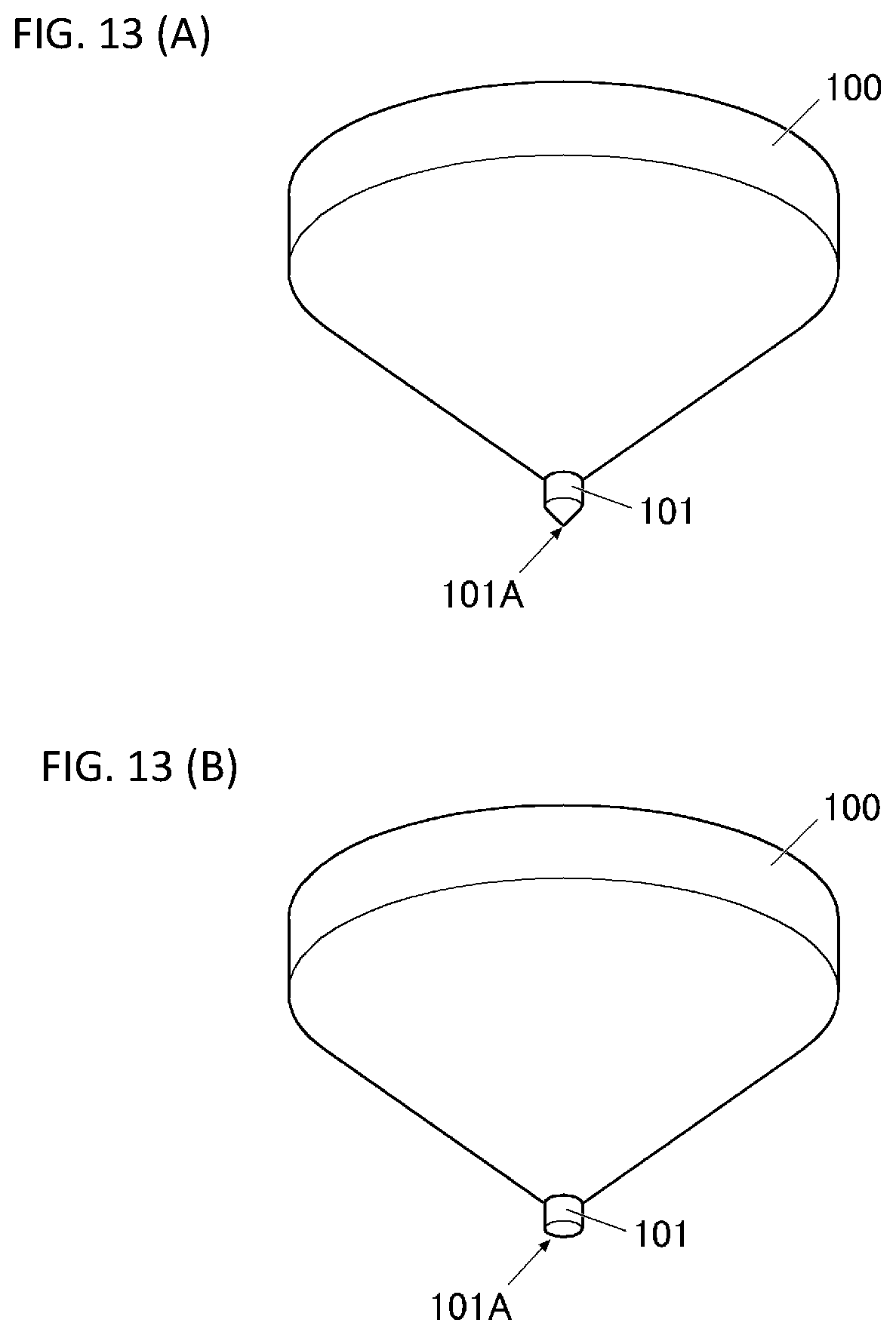
[0006] Further, as shown in FIG. 13(A) as an example, when the shape of the terminal end 101A of the shaft part 101 of the spinning top toy 100 is a conical shape or a spherical shape, etc. and a ground contact area is small on a play board surface such as a play board, a plate surface, a ground surface, etc., the spinning top toy 100 rotates and stays at one location on the play board surface. As shown in FIG. 13(B), when the terminal end 101A of the shaft part 101 of the spinning top toy 100 is a flat shape, etc. and the ground contact area is large on the play board surface, the spinning top toy 100 rotates and moves on the play board surface.
[0007] In the spinning top toy disclosed in Patent Document 1, the spinning top toy is configured by assembling an upper member which is the part attacking the opponent's spinning top toy by collisions, a middle member which determines the height of the spinning top toy, and a lower member which determines the rotation type of the spinning top toy.
[0008] By changing the shape of the terminal end of the shaft part formed at the lower member, the player can change the rotation type or determine whether or not the spinning top toy moves. Further, by changing a fixed position of the second middle member with respect to the first middle member which configures a middle member, the player can change the height of the spinning top toy.
[0009] With this, in the spinning top toy disclosed in Patent Document 1, the player can freely change the height or the rotation type of the spinning top toy, or determine whether or not the spinning top toy moves.
[0010] While changing the configuration of the spinning top toy, the player can create various ways to develop the battle games advantageously, so that the battle games become more enjoyable.
[0011] [Patent Document 1] Japanese Registered Utility Model Patent No. 3149384
SUMMARY
Problems to be Solved by the Invention
[0012] However, in such spinning top toy disclosed in Patent Document 1, a plurality of lower members having different shapes of the terminal end of the shaft part was prepared in advance, and the shape of the terminal end of the shaft part could be changed by replacing the lower member.
[0013] Therefore, the player had to remove the lower member from the spinning top toy and replace different lower member to change the shape of the terminal end of the shaft part, so that the player felt troublesome. Also, there was a possibility of losing the lower member.
[0014] Further, when the height of the spinning top toy changed, the player removed the screw which connected the upper member, the middle member, and the lower member, and the middle member was taken out and the fixed position of the second middle member with respect to the first middle member was changed. After that, the upper member, the middle member, and the lower member had to be connected by the screw again. However, the player felt troublesome with these operations.
[0015] Further, in the spinning top toy disclosed in Patent Document 1, the player chose only one of the states in which the height of the spinning top toy was high or low. Therefore, the player could not perform fine adjustment of the height of the spinning top toy and the player may lose interest.
[0016] The present invention was created considering the aforementioned conventional status. An object is to provide a spinning top toy which is capable of performing fine adjustment of a height with a simple operation without replacing a part and is capable of changing a rotation type (including a determination whether or not the spinning top toy moves).
Means for Solving the Problems
[0017] A spinning top toy includes a body, a shaft part. The body is arranged to collide with an opponent's spinning top toy, and the shaft part is arranged under the body to contact a play board surface. The shaft part extends in a vertical direction.
[0018] The shaft part includes a base component including a recessed part, a rotation component, a shaft body component, and a shaft.
[0019] The rotation component is rotatable in a circumferential direction. The rotation component is inserted into the recessed part of the base component. The rotation component is at least partially cylindrical. The shaft body component is configured in the rotation component. The shaft body component is movable in the vertical direction by rotating the rotation component. The shaft is configured in the shaft body component. The shaft includes a terminal end. The terminal end is retractable in the shaft body component by rotating the rotation component.
[0020] A lower end of the shaft body component is always lower than a lower end of the rotating component in the vertical direction.
BRIEF DESCRIPTION OF THE DRAWINGS
[0021] FIGS. 1(A) and 1(B) are diagrams explaining how to play with a spinning top toy according to an embodiment of the present invention.
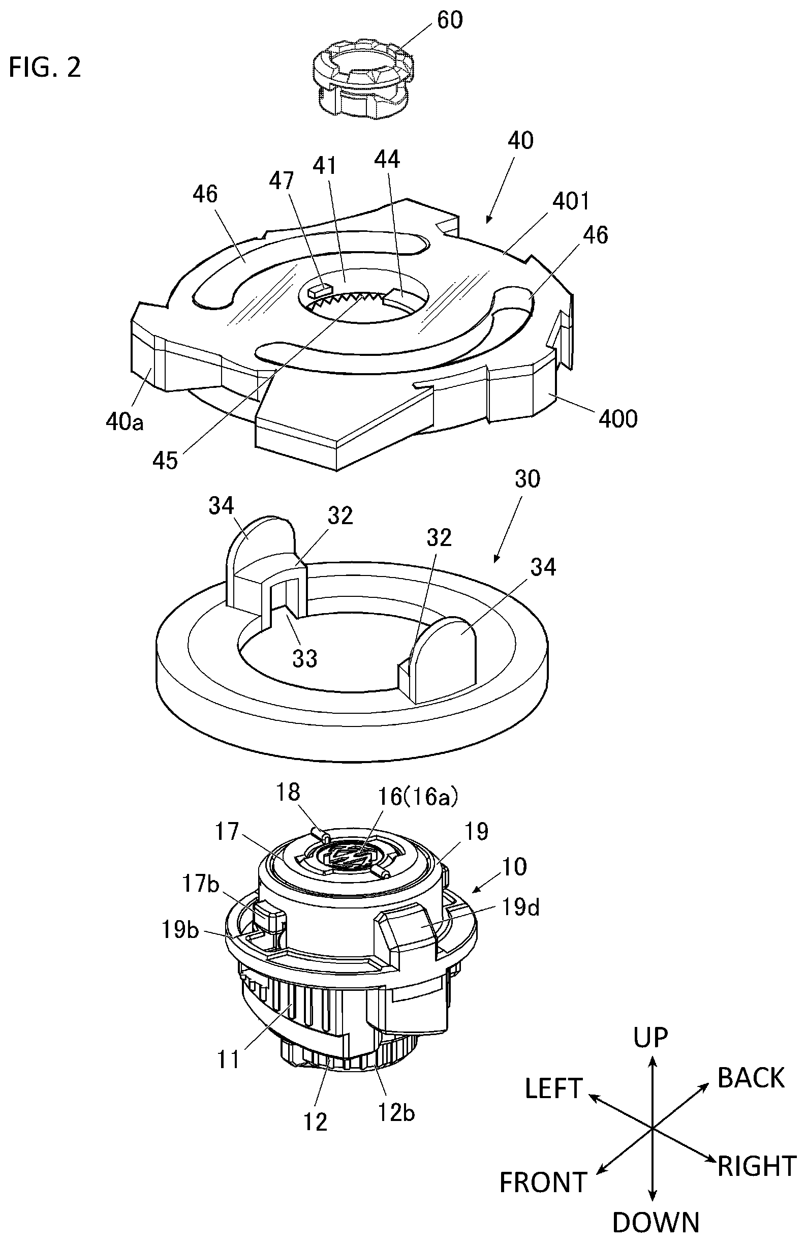
[0022] FIG. 2 is an exploded perspective view showing a spinning top toy according to the present embodiment.
[0023] FIG. 3 is an exploded cross-sectional perspective view showing the spinning top toy according to the present embodiment;
[0024] FIG. 4 is an exploded perspective view showing a shaft part of the spinning top toy according to the present embodiment.
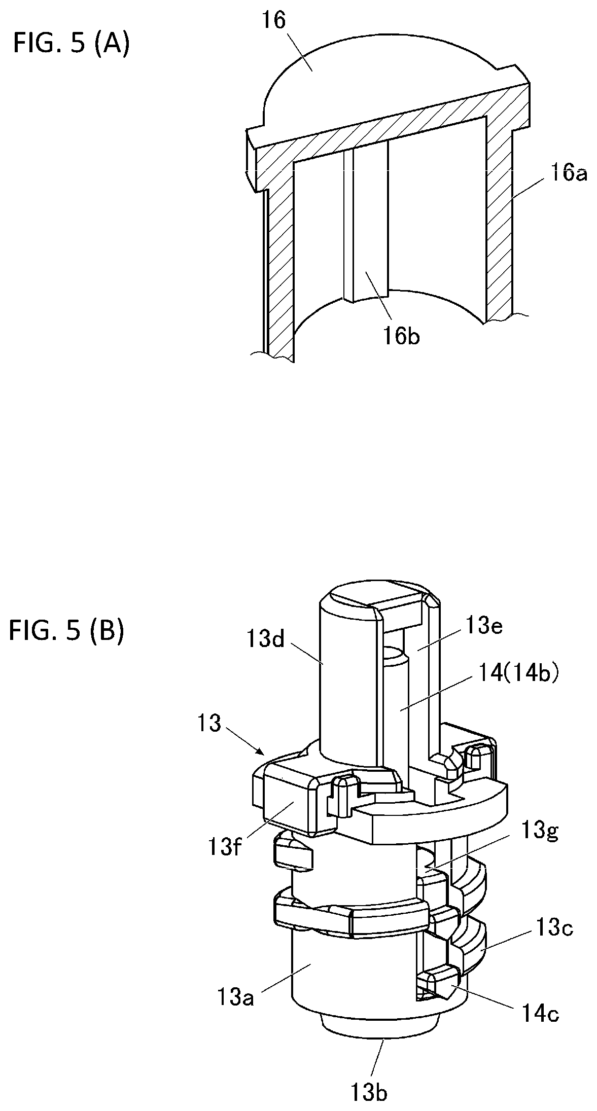
[0025] FIG. 5(A) is an illustration showing a protruding part provided on an inner surface of a cylindrical part of a regulating component.
[0026] FIG. 5(B) is an illustration showing a recessed part (opening) provided on a side surface of a guide part of a shaft body component.
[0027] FIG. 6 is a perspective view showing a structure of a shaft.
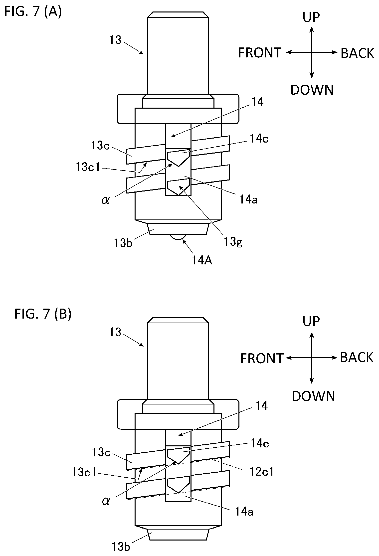
[0028] FIG. 7(A) is a diagram showing a state in which a lower end of the protruding part of the shaft is positioned lower than a lower surface of a male screw.
[0029] FIG. 7(B) is a diagram showing a state in which the lower end of the protruding part of the shaft and the female screw of the rotation component are engaged.
[0030] FIG. 8 is a plane view showing a structure of a rotation component.
[0031] FIGS. 9(A) and 9(B) are explanatory diagrams showing how to push up a corner part, which faces a notch part of the female screw of the rotation component, by abutting on an inclined surface of the protruding part of the shaft.
[0032] FIGS. 10(A) and 10(B) are diagrams showing an engagement relationship with a body, a shaft part, and a flywheel of the spinning top toy of the present embodiment. FIG. 10(A) shows a disassembled state. FIG. 10(B) shows an assembled state.
[0033] FIGS. 11(A)-(C) are diagrams showing a projection length of the shaft body component, a state of the terminal end of the shaft, etc. when the rotation angle of the rotation component is (A) 0 degree, (B) 90 degrees, and (C) 180 degrees.
[0034] FIGS. 12(A) and 12(B) are diagrams showing a projection length of the shaft body component, a state of the terminal end of the shaft, etc. when the rotation angle of the rotation component is (A) 270 degrees and (B) 360 degrees.
[0035] FIG. 13(A) is a diagram showing in a case that a ground contact area between the terminal end of the shaft part of the spinning top toy and a play board surface is small.
[0036] FIG. 13(B) is a diagram showing in a case that the ground contact area between the terminal end of the shaft part of the spinning top toy and the play board surface is large.
DETAILED DESCRIPTION OF PREFERRED EMBODIMENTS
[0037] Hereinafter, a spinning top toy of the present invention will be described based on embodiments shown in the drawings.
Whole Structure
[0038] FIGS. 1(A) and 1(B) are diagrams explaining how to play with a spinning top toy according to an embodiment of the present invention. FIG. 2 is an exploded perspective view showing a spinning top toy according to the present embodiment. FIG. 3 is an exploded cross-sectional perspective view showing the spinning top toy according to the present embodiment. FIG. 4 is an exploded perspective view showing a shaft part of the spinning top toy according to the present embodiment.
[0039] In the present specification, the terms "up", "down", "left", "right", "front", and "back" refer to the corresponding directions in FIGS. 2 and 3.
[0040] The spinning top toy 1 of the present embodiment is the spinning top toy which is capable of being used for battle games.
[0041] Hereinafter, it explains the spinning top toys 1 which can be used for battle games in which the spinning top toys 1 collide with each other and the opponent's spinning top toy 1 is disassembled by the impact force as shown in FIG. 1(B), so that one of players wins. The spinning top toy 1 according to the present invention may not be such spinning top toy which is capable of being disassembled.
[0042] As shown in FIGS. 2 and 3, the spinning top toy 1 is provided with a shaft part 10 which configures a lower part structure and becomes a driver contacting to a play board surface such as a play board, a plate surface, a ground, etc., a performance variable ring 30 which becomes a layer configuring an upper part structure, and a body 40 which collides with an opponent's spinning top toy.
Detail Structure
1. Regarding Shaft Part 10
[0043] As shown FIGS. 2 to 4, the shaft part 10 is provided with a base component 11, a rotation component 12, a shaft body component 13, a shaft 14, a regulating component 16, a pressing component 17, and a cover 19.
[0044] The base component 11 is formed in a bowl shape, and a circular-shaped hole 11b is formed in the bottom part of the recessed part 11a. On the upper surface and each of the right and left side surfaces of the base component 11, a groove 11c recessed downwardly is formed, and a screw inserting hole 11d is formed in each groove 11c.
[0045] In the hole 11b of the base component 11, approximately cylindrical-shaped rotation component 12 is inserted. A cylindrical part 12a of the upper part of the rotation component 12 is fitted into the recessed part 11a of the base component 11 in a rotation manner in its circumferential direction inside the recessed part 11a of the base component 11.
[0046] In the lower part of the rotation component 12, an approximately cylindrical-shaped adjusting part 12b, which is concentric with the cylindrical part 12a and has slightly smaller diameter, is integrally formed with the cylindrical part 12a. The adjusting part 12b is positioned lower side than the lower end of the base component 11 and is exposed outside downwardly from the base component 11.
[0047] Further, a female screw 12c is formed on the inner surface of the adjusting part 12b of the rotation component 12. By the way, in the present embodiment, notch parts 12c2 (described later and see FIG. 8) are provided at predetermined positions of the female screw 12c, and this will be described later.
[0048] A shaft body component 13 is arranged inside the rotation component 12. In the lower part of the shaft body component 13, a cylindrical-shaped storage part 13a storing a shaft 14, which will be described later, is provided, and at the lower end of the storage part 13a, a cylindrical-shaped lower end part 13b, which is concentric with the cylindrical part 13a and has slightly smaller diameter, is extended.
[0049] At the outside of the side surface of the storage part 13a of the shaft body component 13, a male screw 13c is formed, and inside rotation component 12, the shaft body component 13 is screwed to the rotation component 12. In the present embodiment, an opening part 13g is provided on the side surface of the storage part 13a of the shaft body component 13, and this point will be described later.
[0050] The movement of the shaft body component 13 is restricted by a regulating component 16 in order not to be rotated in the circumferential direction with respect to the base component 11 which will be described later. Accordingly, even when the rotation component 12 is rotated in the circumferential direction with respect to the base component 11 by operating the adjusting part 12b of the rotation component 12 by a player as described later, the shaft body component 13 is not rotated in the circumferential direction and it is moved in the vertical direction by the rotation of the rotation component 12.
[0051] Therefore, by rotating the rotation component 12 in the circumferential direction, the projection length L (see FIGS. 11(A) to 11(C), and FIGS. 12(A) and 12(B) as described later) of the lower end part 13b of the shaft body component 13 can be set long or short in the lower direction from the lower end of the rotation component 12.
[0052] In this case, even when the rotation component 12 is rotated within the range of the rotatable angle, the lower end part 13b of the shaft body component 13 is not retracted inside the rotation component 12. That is, even when the shaft body component 13 is moved in the vertical direction by rotating the rotation component 12, it is maintained in a state in which the lower end part 13b of the shaft body component 13 is positioned lower than the lower end of the rotation component 13.
[0053] Further, at the upper part of the shaft body component 13, a cylindrical-shaped guide part 13d, which is concentric with the cylindrical part 13a and has slightly smaller diameter, is provided.
[0054] Inside the shaft body component 13, a shaft 14 is stored. At the lower part of the shaft 14, a cylindrical-shaped main body part 14a in which the lower end is formed in a downwardly projecting shape is provided. Hereinafter, the lower end of the main body part 14a of the shaft 14 is called as a terminal end A of the shaft 14.
[0055] In the main body part 14a of the shaft 14, its outer diameter is formed in the same size or slightly smaller size than the inner diameter of the storage part 13a of the shaft body component 13, so that it can be moved in the vertical direction along the storage part 13a of the shaft body component 13.
[0056] Further, at the upper part of the shaft 14, a cylindrical-shaped bar-shaped part 14b, which is concentric with the cylindrical part 14a and has slightly smaller diameter, is integrally provided with the main body part 14a. In the bar-shaped part 14b of the shaft 14, its outer diameter is formed in the same size or slightly smaller size than the inner diameter of the guide part 13d of the shaft body component 13.
[0057] The bar-shaped part 14b of the shaft 14 is inserted inside the guide part 13d of the shaft body component 13, and it is guided by the guide part 13d and restricted to only move in the vertical direction (that is, the bar-shaped part 14b is not move in the front and back direction or the right and left direction), so that when the main body part 14a of the shaft 14 is moved inside the storage part 13a of the shaft body component 13, it can be moved smoothly in the vertical direction without ratting in the front, back, right, and left directions.
[0058] A spring 15, which is an urging member, is arranged between the external wall of the bar-shaped part 14b of the shaft 14 and the internal wall of the storage part 13a of the shaft body component 13. The main body part 14a of the shaft 14 is urged downward inside the shaft body component 13 by the urging force of the spring 15.
[0059] However, since the outer diameter of the main body part 14a of the shaft 14 is larger than the inner diameter of the lower end part 13b of the shaft body component 13, even when the main body part 14a of the shaft, which is urged, is moved downward inside the storage part 13 of the shaft body component 13, it is engaged with the lower end part 13b of the shaft body component 13. Therefore, the shaft 14 does not come off downwardly from the shaft body component 13.
[0060] In the present embodiment, a protruding part 14c is provided on the side surface of the main body part 14a of the shaft 14, and this point will be described later.
[0061] On the other hand, the guide part 13d of the upper part of the shaft body component 13 is inserted inside a cylindrical part 16a of the regulating component 16. The cylindrical part 16a of the regulating component 16 has a structure in which the inside is a hollow and the lower side has an opening. As shown in FIG. 4, a hook B is provided in each of the front and back sides on the side surface of the upper end of the cylindrical part 16a of the regulating component 16.
[0062] As shown in FIG. 5(A), at a predetermined position on the inner surface of the cylindrical part 16a of the regulating component 16, a ridge-shaped protruding part 16b, which extends in the vertical direction, is provided.
[0063] Further, as shown in FIG. 5(B), on the side surface of the guide part 13d of the shaft body component 13, a recessed part 13e (in this case, an opening), which extends downwardly, is provided. FIG. 5(B) shows a state in which the shaft body component 13 is rotated 180 degrees around its central axis.
[0064] When the guide part 13d of the shaft body component 13 is inserted inside the cylindrical part 16a of the regulating component 16, the protruding part 16b of the cylindrical part 16a of the shaft body component 13 is fitted to the recessed part 13e of the guide part 13d of the shaft body component 13. The shaft body component 13 cannot be rotated around its central axis, so that it becomes the state in which the vertical movement along the protruding part 16b inside the cylindrical part 16a of the regulating component 16 is only permitted.
[0065] With this, the circumferential direction movement (that is, rotation around the central axis) of the shaft body component 13 is restricted by the regulating component 16, so that as described above, even when the rotation component 12 is rotated in the circumferential direction with respect to the base component 11 by operating the adjusting part 12b of the rotation component 12, the shaft body component 13 is not rotated in the circumferential direction and it is only moved in the vertical direction.
[0066] In the state in which the shaft body component 13 is moved at the highest position, as shown in FIG. 3, the shoulder parts 13f provided at the front and back of the shaft body component 13 are fitted to the holes 16c provided in the regulating component 16.
[0067] Further, a projecting piece 16d is formed in each right and left of the lower end part of the regulating component 16, and a circular-shaped hole 16e is formed in each projecting piece 16d. Each projecting piece 16d of the regulating component 16 is fitted to each groove 11c of the base component 11, and in this state, each hole 16e of the regulating component 16 is arranged directly above each screw inserting hole 11d of the base component 11.
[0068] In the cylindrical part 16a of the regulating component 16, a pressing component 17 is arranged in a manner surrounding its outer periphery. A circular-shaped opening 17a is formed on the upper surface of the pressing component 17, and the cylindrical part 16a of the regulating component 16 is fitted to the opening 17a of the pressing component 17. The upper surface of the cylindrical part 16a of the regulating component 16 is exposed outside. The upper surface of the pressing component 17 and the upper surface of the cylindrical part 16a of the regulating component 16 become flush.
[0069] Further, on the upper surface of the pressing component 17, in the symmetrical positions (two sections), protruding strips (projections) 18, which extend in a radial direction, are formed. Further, a leg part 17b, which projects in each of the front and back direction, is provided at the outer circumferential lower end part of the pressing component 17. They pass through the holes 19c provided in a cover 19 described later, and are engaged with the cover 19.
[0070] The cover 19 is arranged around the pressing component 17. The cover 19 is provided with a cylindrical part 19a and a flange 19b which is formed in an annular shape in the lower end part of the cylindrical part 19a. The holes 19c are respectively formed in the front and back side of the cylindrical part 19a and the flange 19b.
[0071] Further, a projection part 19d is formed in each of the right and left sides of the cylindrical part 19a, and the outer surface of the projection parts 19d become flush with the outer peripheral surface of the flange 19b.
[0072] On the lower surface of each of the projection parts 19d, a cylindrical body 19e, which projects downwardly, is formed, and each cylindrical body 19 e is fitted to the hole 16e of the projecting piece 16d of the regulating component 16. Further, at the center of each cylindrical body 19e, a female screw part 19f which opens downwardly is formed.
[0073] As described above, the holes 16e of the regulating component 16 are arranged directly above the screw inserting holes 11d of the base component 11. As described above, the cylindrical bodies 19e of the cover 19 are fitted to the holes 16e of the regulating component 16, so that the female screw parts 19f provided in the cylindrical bodies 19e of the cover 19 are positioned directly above the screw inserting holes 11d of the base component 11.
[0074] Therefore, in the shaft part 10 of the spinning top toy 1 of the present embodiment, by inserting the screws 20 upwardly to the screw inserting holes 11d from lower side and screwing to the female screw parts 19f, the regulating component 16 and the cover 19 are screwed and fixed to the base component 11.
[0075] Further, the pressing component 17 is also fixed to the base component 11 through the regulating component 16 or the cover 19.
[0076] As described above, in the shaft part 10 of the spinning top toy 1 of the present embodiment, the regulating component 16, the pressing component 17, and the cover 19 are fixed to the base component 11 and do not move relative to the base component 11.
[0077] The rotation component 12 can be rotated in the circumferential direction with respect to the base component 11. The shaft body component 13 can be moved in the vertical direction with respect to the base component 11 by rotating the rotation component 12.
[0078] Further, the shaft 14 is urged downwardly inside the storage part 13a of the shaft body component 13 by the resilience force of the spring 15, but it can be moved in the vertical direction inside the storage part 13a of the shaft body component 13.
Regarding Mechanism for Projecting or Retracting the Terminal End A of the Shaft 14 from or into the Lower End of the Shaft Body Component 13
[0079] On the other hand, in the shaft part 10 of the spinning top toy 1 of the present embodiment, when the rotation component 12 is rotated in the circumferential direction with respect to the base component 11, as described above, the shaft body component 13 is moved in the vertical direction, and at the same time, the terminal end A of the shaft 14 can be automatically projected from or retracted into the lower end (that is, the lower end part 13b) of the shaft body component 13 (that is, it is projected downwardly from the lower end of the shaft body component 13 or it is retracted into the lower end of the shaft body component 13).
[0080] In the present embodiment, by only rotating the rotation component 12, the terminal end A of the shaft 14 can be projected from or retracted into the lower end part 13b of the shaft body component 13.
[0081] Hereinafter, the mechanism for projecting or retracting the terminal end A of the shaft 14 from or into the lower end of the shaft body component 13 will be described.
[0082] As shown in FIG. 6, in the present embodiment, in the main body part 14a of the shaft 14, a protruding part 14c is provided in a manner projecting each of the right and left directions from the side surface.
[0083] Hereinafter, it will be described under the presumption that the protruding parts 14c are projected from the right and left of the main body part 14a of the shaft 14, but the protruding parts 14c can be provided in different positions such as the front and back, etc., of the main body part 14a of the shaft 14. In the present invention, it is not limited to the case in which the protruding parts 14c are provided in the right and left of the main body part 14a of the shaft 14.
[0084] In the present embodiment, the protruding parts 14c are provided in each of the upper side and the lower side of the main body part 14a of the shaft 14 (2 in each of the right and left sides, 4 in total), and they are integrally formed with the main body part 14a of the shaft 14.
[0085] Further, the protruding parts 14c are formed in a wedge-shape projected downwardly and have the inclined surfaces 14c1, 14c2 in the front and back of its lower surfaces. Hereinafter, the boarder parts of the inclined surfaces 14c1, 14c2 (that is, the wedge-shaped lower end parts) are called as a lower end a of the protruding parts 14c.
[0086] Further, as shown in FIGS. 4 and 5(B), in a predetermined position on each of the right and left side surfaces of the storage part 13a of the shaft body component 13, a long and narrow opening part 13g is formed in the vertical direction. The protruding parts 14c of the shaft 14 stored inside the storage part 13a of the shaft body component 13 pass through the opening parts 13g and project outside the storage part 13a.
[0087] The male screw 13c of the shaft body component 13 is separated by the part of the opening parts 13g. Further, the terminal end surfaces of the protruding parts 14c of the shaft 14 become flush with the outer peripheral surface of the male screw 13c of the shaft body component 13.
[0088] As described above, in the case in which the main body part 14a of the shaft 14, which is urged downwardly by the spring 15, is located at the lowest position inside the storage part 13a of the shaft body component 13, as shown in FIG. 7(A), the terminal end A of the shaft 14 is projected downwardly from the lower end part 13b of the shaft body component 13.
[0089] In this state, the lower end a of the protruding part 14c of the shaft 14 is positioned lower than the lower surface 13c1 of the male screw 13c of the shaft body component 13. As described above, in the part of the protruding part 14c of the shaft 14, that is, the part of the opening part 13g, the male screw 13c is not existed due to the separation of the male screw 13c. Therefore, hereinafter, it is expressed that the lower end a of the protruding part 14c of the shaft 14 is positioned lower than the lower surface 13c1 of the male screw 13c, but, to be accurate, it is positioned lower than a virtual surface connecting the lower surface 13c1 of the male screw 13c of both sides (front and back) of the opening parts 13g of the shaft body component 13.
[0090] However, since the shaft body component 13 is screwed to the rotation component 12, the upper surface 12c1 of the female screw 12c provided on the inner surface of the rotation component 12 (see dashed line in FIG. 7(B)) abuts on the lower surface 13c1 of the male screw 13c of the shaft body component 13.
[0091] In this state, as shown in FIG. 7(B), the protruding part 14c of the shaft 14 is pushed up, and the lower end a of the protruding part 14c of the shaft 14 and the upper surface 12c1 of the female screw 12c are engaged. That is, it becomes the state in which the main body part 14a of the shaft 14 is pushed up inside the storage part 13a of the shaft body component 13, and in this state, the terminal end A of the shaft 14 is retracted inside the lower end part 13b of the shaft body component 13.
[0092] In this state, even when the player rotates the rotation component 12 in the circumference direction by operating the adjusting part 12b of the rotation component 12, it maintains the state in which the lower end a of the protruding part 14c of the shaft 14 and the upper surface 12c1 of the female screw 12c are engaged, so that it becomes the state in which the terminal end A of the shaft 14 is retracted inside the lower end part 13b of the shaft body component 13.
[0093] As described above, when the rotation component 12 is rotated, the shaft body component 13 itself is moved in the vertical direction inside the rotation component 12, so that in this case, the shaft body component 13 and the shaft 14 are moved in the vertical direction in the state in which the terminal end A of the shaft 14 is retracted inside the lower end part 13b of the shaft body component 13.
[0094] In the present embodiment, when viewing the rotation component 12 from the upper side, as shown in FIG. 8, in the female screw 12c, the notch parts 12c2 at predetermined positions (in this case, two sections symmetrical to the central axis of the cylindrical-shaped rotation component 12) are provided.
[0095] Therefore, when the player rotates the rotation component 12 in the circumferential direction by operating the adjusting part 12b of the rotation component 12 and the rotation component 12 is rotated at a predetermined rotation position, that is, when the notch parts 12c2 of the female screw 12c are rotated in the positions of the protruding parts 14c of the shaft 14, the engagement of the protruding parts 14c of the shaft 14 and the upper surface 12c1 of the female screw 12c are released. With this, the main body part 14a of the shaft 14 is moved to the lowest position inside the storage part 13a of the shaft body component 13 by the urging force of the spring 15, and as shown in FIG. 7(A), the terminal end A of the shaft 14 is projected downwardly from the lower end part 13b of the shaft body component 13.
[0096] Further, when the player rotates the rotation component 12 in the circumferential direction by operating the adjusting part 12b of the rotation component 12 and the rotation component 12 is rotated at a rotation position other than a predetermined rotation position, that is, when the part other than the notch parts 12c2 of the female screw 12c is rotated in the positions of the protruding parts 14c of the shaft 14, the lower end a of the protruding part 14c of the shaft 14 and the upper surface 12c1 of the female screw 12c are engaged. Therefore, the main body part 14a of the shaft 14 is pushed upwardly inside the storage part 13a of the shaft body component 13 against the urging force of the spring 15. As shown in FIG. 7(B), the terminal end A of the shaft 14 is retracted inside the lower end part 13b of the shaft body component 13.
[0097] In the present embodiment, with this, by rotating the rotation component 12 in the circumferential direction, the terminal end A of the shaft 14 is automatically projected downwardly from the lower end part 13b of the shaft body component 13 or retracted inside the lower end part 13b of the shaft body component 13, that is, it is projected and retracted automatically.
[0098] By only rotating the rotation component 12 by the player, the terminal end A of the shaft 14 can be projected from and retracted into the lower end part 13b of the shaft body component 13.
[0099] As described above, when the rotation component 12 is rotated, the lower end a of the protruding part 14c of the shaft 14 is raised from the state positioned lower than the lower surface 13c1 of the male screw 13c to the position engaging with the upper surface of the female screw 12c.
[0100] In this case, as shown in FIG. 9(A), when the rotation component 12 is rotated, the corner part of the upper side facing the notch parts 12c2 of the female screw 12c of the rotation component 12 abuts on the inclined surfaces 14c1 of the protruding parts 14c of the shaft 14. When the rotation component 12 is further rotated, the corner part of the upper side of the female screw 12c pushes up the inclined surface 14c1 while sliding the inclined surfaces 14c1 of the protruding parts 14c of the shaft 14.
[0101] Therefore, the protruding parts 14c of the shaft 14 are smoothly pushed up by rotating the rotation component 12, as shown in FIG. 7(B), and it is smoothly pushed up until it becomes the state in which the lower end a of the protruding part 14c of the shaft 14 and the upper surface 12c1 of the female screw 12c are engaged. Similarly, when the rotation component 12 is rotated in the opposite direction, as shown in FIG. 9(B), the corner part of the upper side the female screw 12c of the rotation component 12 abuts on the inclined surfaces 14c2 of the protruding parts 14c of the shaft 14 and pushes it up, so that the protruding parts 14c of the shaft 14 are pushed up until it becomes the state shown in FIG. 7(B).
[0102] In the present embodiment, accordingly, by rotating the rotation component 12, the terminal end A of the shaft 14 can be easily and smoothly projected from and retracted into the lower end part 13b of the shaft body component 13.
[0103] In the spinning top toy 1 of the present embodiment, in the state in which the terminal end A of the shaft 14 is projected downwardly from the lower end part 13b of the shaft body component 13, the terminal end A of the shaft 14, which is projected downwardly, contacts to a play board surface, so that the ground contact area on the play board surface becomes small and it becomes the state in which the spinning top toy 1 rotates and stays at one location on the play board surface.
[0104] Further, in the state in which the terminal end A of the shaft 14 is retracted inside the lower end part 13b of the shaft body component 13, the lower end part 13b of the shaft body component 13 itself contacts to the play board surface, so that the ground contact area on the play board surface becomes large, and it becomes the state in which the spinning top toy 1 is moved on the play board surface while rotating.
2. Regarding Performance Variable Ring 30
[0105] In this embodiment, a flywheel is used as a performance variable ring 30 (see FIGS. 2 and 3). The performance variable ring 30 has a plate like shape. As shown in FIG. 3, at the bottom surface of the performance variable ring 30, an annular step part 31, which is capable of storing the flange 19b of the shaft part 10 from the lower side, is formed. Further, as shown in FIGS. 2 and 3, on the upper surface of the performance variable ring 30, a projection part 32, which stretches out in the upper direction, is formed at each of two sections which are faced each other in the right and left direction across the axis line of the rotating shaft (that is, central axis of the shaft body component 13 or the shaft 14, etc. of the shaft part 10). In the lower side part of each projection part 32, a recessed part 33, which is capable of storing the projection part 19d of the shaft part 10 from the lower side, is formed. Further, on the upper surface of the performance variable ring 30, a tongue-piece part 34, which extends upward, is formed directly outside each projection part 32. The tongue-piece part 34 is projected higher than the projection part 32. As the performance variable ring 30, substituting the flywheel or integrating with the flywheel, there may be one having a projection part on the outer peripheral surface, so as to easily attack the opponent's spinning top toy 1, or there may be one having a recessed part on the outer peripheral surface, so as to hardly receive the attack from the opponent's spinning top toy 1.
3. Regarding Body 40
[0106] The body 40 has a disk shape. As shown in FIG. 2, the body 40 is provided with a base 400 and a transparent cover body 401 which has a substantially identical shape with the base 400 viewed from top and which is covered on the base 400.
[0107] In the outer peripheral of the body 40, protrusions and recesses 40a are formed. Further, at the center of the base 400, a circular hole 41 is formed. The aforementioned transparent cover body 401 covers the part except the circular hole 41, etc. Further, on the lower surface of the body 40, an annular-shaped recessed part 42 which is capable of storing the projection part 32 of the performance variable ring 30 from the lower side is formed.
[0108] At the lower end of the inner circumferential surface of the inner circumferential wall 43a which partitions and forms the annular-shaped recess part 42, a hook (engagement part) 44 which overhangs in the inward radial direction is projected at each of two sections which are faced each other in the front-and-back direction across the axis line of the rotating shaft.
[0109] Further, at the middle region in the vertical direction of the inner circumferential surface of the inner circumferential wall 43a, a protrusion 47 which overhangs in the inward radial direction is projected at each of two sections which are faced each other in the right-and-left direction across the axis line of the rotating shaft.
[0110] In addition, on the lower end surface of the inner circumferential wall 43a, a raised part 45 in which protrusions and recesses are continuously formed so as to mesh with the aforementioned protruding strips 18 is formed at each of two sections which are faced each other in the right-and-left direction across the axis line of the rotating shaft.
[0111] Further, at the ceiling wall 43b which partitions and forms the annular-shaped recess part 42 of the body 40, an arcuate slit 46, which is capable of inserting the tongue-piece part 34 of the performance variable ring 30 from the lower side, is formed. The arcuate slit 46 has a length in which the tongue-piece part 34 can be sufficiently moved.
4. Regarding Identification Part 60
[0112] In the circular hole 41, an identification part 60 is mounted. The identification part 60 is used for identifying the spinning top toy 1 or the identification of a player.
[0113] For the identification, in the present embodiment, not shown in the drawings, a plurality of identification parts in which decorations and/or colors, etc. are different are offered, and one of the identification parts 60 which is selected by the player is mounted in the circular hole 41 by using the projections 47 in a screw manner.
Assembly Method
[0114] Next, an example of an assembly method of the spinning top toy 1 will be described.
[0115] First, the rotation component 12 is fitted to the hole 11b of the recessed part 11a of the base component 11 of the shaft part 10 in a rotatable manner in the circumferential direction. In this case, the adjusting part 12b of the rotation component 12 is arranged in the position lower than the lower end of the base component 11 and exposed outside in the lower side of the base component 11. The male screw 13c formed on the side surface of the shaft body component 13 is screwed into the female screw 12c formed on the inner surface of the rotation component 12. The shaft 14 is stored inside the shaft body component 13. In a manner in which the protruding part 16b of the cylindrical part 16a of the regulating component 16 is fitted to the recessed part 13e provided in the guide part 13d of the shaft body component 13, the guide part 13d of the shaft body component 13 is inserted into the cylindrical part 16a of the regulating component 16. Next, each projecting piece 16d of the regulating component 16 is fitted to each groove 11c of the base component 11. Next, the leg parts 17b of the pressing component 17 pass through the holes 19c of the cover 19 and the pressing component 17 and the cover 19 are engaged, and in this state, the pressing component 17 and the cover 19 cover the regulating component 16. Next, the cylindrical bodies 19e on the lower surfaces of the projection parts 19d of the cover 19 are fitted into the holes 16e of the regulating component 16. The regulating component 16 and the cover 19 are fixed to the base component 11 by inserting the screws 20 into the screw inserting holes 11d from the lower side and screwing to the female screw parts 19f. In this way, the shaft part 10 is assembled.
[0116] Next, in a manner in which the projection parts 19d of the shaft part 10 are fitted to the recessed parts 33 of the performance variable ring 30 from the lower side, the shaft part 10 and the performance variable ring 30 are assembled. The assembled body brings to the position close to the body 40 from the lower side. In this case, the tongue piece parts 34 of the performance variable ring 30 of the aforementioned assembled body are fitted to the predetermined ends of the arcuate slits 46 of the body 40 (see FIG. 10(A)). In this state, it is the state in which the hooks B of the shaft part 10 and the hooks 44 of the body 40 are not overlapped in the vertical direction. This state is the disassembled state. After that, the shaft part 10 of the aforementioned assembled body pushes to the body 40 side. Then, first, the performance variable ring 30 is pushed to the lower surface of the body 40, and further, the hooks B of the shaft part 10 are relatively pushed up to the position higher than the hooks 44 of the body 40. The shaft part 10 is rotated with respect to the body 40 integrated with the performance variable ring 30 until the tongue-piece parts 34 move to the ends opposite side of the aforementioned predetermined ends (see FIG. 10(B)). In this case of the rotation, the body 40 and the performance variable ring 30 and the shaft part 10 are relatively rotated, and in FIG. 10(B), it shows the state in which the body 40 is rotated with respect to the performance variable ring 30. Then, it becomes the state in which the hooks B of the shaft part 10 and the hooks 44 of the body 40 are overlapped in the vertical direction. When releasing the shaft part 10, the lower surface of the hooks B of the shaft part 10 and the upper surface of the hooks 44 of the body 40 are abutted.
[0117] The state in which the lower surface of the hooks B of the shaft part 10 and the upper surface of the hooks 44 of the body 40 are abutted is the assembled state. With this, the shaft part 10, the performance variable ring 30 and the body 40 are connected, and the spinning top toy 1 is assembled.
How to Play
[0118] Next, an example of how to play with the spinning top toy 1 will be described.
[0119] In the example of how to play, specifically, the changes for the fine adjustment of the height or the rotation type (including a determination whether or not the spinning top toy moves) of the spinning top toy 1 will be described.
[0120] For example, the player holds the body 40, etc. of the spinning top toy 1 by one hand, and the player grasps and rotates the adjusting part 12b of the rotation component 12 of the shaft part 10 in the circumferential direction by the other hand, and the shaft body component 13 is raised up with respect to the rotation component 12.
[0121] When the rotation component 12 is rotated in the predetermined rotation position (hereinafter, this rotation position is called as a rotation angle 0 degree) and the notch parts 12c2 of the female screw 12c of the rotation component 12 are rotated at the positions of the protruding parts 14c of the shaft 14, the engagement of the protruding parts 14c of the shaft 14 and the upper surfaces 12c1 of the female screw 12c is released. Therefore, the main body part 14a of the shaft 14 is moved in the lowest position inside the storage part 13a of the shaft body component 13 by the urging force of the spring 15, and as shown in FIG. 11(A), the terminal end A of the shaft 14 is projected downwardly from the lower end part 13b which is the lower end of the shaft body component 13.
[0122] In this state, when the player rotates the spinning top toy 1 on the play board surface, it becomes the state in which the terminal end A of the shaft 14 grounds on the play board surface, and the ground contact area of the play board surface becomes small, so that the spinning top toy 1 rotates and stays at one location on the play board surface.
[0123] Further, when the player rotates the adjusting part 12b of the rotation component 12 in the opposite direction in the circumferential direction from the state shown in FIG. 11(A), the protruding parts 14c of the shaft 14 and the upper surface 12c1 of the female screw 12 are engaged, so that the main body part 14a of the shaft 14 is raised up against the urging force of the spring 15 inside the storage part 13a of the shaft body component 13, and the terminal end A of the shaft 14 is retracted inside the lower end part 13b of the shaft body component 13.
[0124] As shown in FIG. 11(B), the shaft 14 is moved in the vertical direction with the shaft body component 13 in the state in which the terminal end A of the shaft 14 is retracted inside the lower end part 13b of the shaft body component 13 while the rotation component 12 is rotated 180 degrees from the position of the rotation angle 0 degree. Depending on the rotation angle of the rotation component 12, the projection length L is changed in the downward direction from the lower end of the rotation component 12 lower end of the lower end part 13b of the shaft body component 13. Accordingly, in the spinning top toy 1 of the present embodiment, the player only rotates the rotation component 12 of the shaft part 10 of the spinning top toy 1, so that the projection length L of the lower end part 13b of the shaft body component 13 can be changed. Therefore, the height of the spinning top toy 1 itself can be changed. In FIG. 11(B), it shows the state in which the rotation component 12 is rotated 90 degrees from the position of the rotation angle 0.
[0125] Further, in this state, when the player rotates the spinning top toy 1 on the play board surface, it becomes the state in which the lower end part 13b of the shaft body component 13 is grounded on the play board surface, and the ground contact area of the play board surface becomes larger than the case in which the terminal end A of the shaft 14 is grounded, so that the spinning top toy 1 moves on the play board surface while rotating. With this, in the spinning top toy 1 of the present embodiment, the player only rotates the rotation component 12 of the shaft part 10 of the spinning top toy 1, and then, the rotation type of the spinning top toy 1 on the play board surface can be changed from the state in which it stays and rotates at one location on the play board surface as described above to the state in which it moves on the play board surface while rotating.
[0126] When the player rotates the adjusting part 12b of the rotation component 12 in the circumferential direction from the state shown in FIG. 11(B), and the rotation component 12 is rotated 180 degrees from the position of the rotation angle 0 degree, as shown in FIG. 11(C), the terminal end A of the shaft 14 is projected from the lower end part 13b of the shaft body component 13.
[0127] When the player further rotates the adjusting part 12b of the rotation component 12 in the circumferential direction, while rotating the rotation component 12 from 180 degrees to 360 degrees in the rotation angle, as shown in FIG. 12(A), the shaft 14 is moved in the vertical direction with the shaft body component 13 in the state in which the terminal end A of the shaft 14 is retracted inside the lower end part 13b of the shaft body component 13, and the projection length L of the lower end part 13b of the shaft body component 13 is changed in response to the rotation angle of the rotation component 12. In FIG. 12(A), it shows the state in which the rotation component 12 is rotated 270 degrees from the position of the rotation angle .theta..
[0128] When the player rotates the adjusting part 12b of the rotation component 12 in the circumferential direction, and the rotation component 12 is rotated 360 degrees, as shown in FIG. 12(B), the terminal end A of the shaft 14 is projected from the lower end part 13b of the shaft body component 13.
[0129] In the aforementioned description, the case in which the rotation component 12 is rotated from the rotation angle 0 degree to 360 degrees, but it does not mean that the rotation component 12 cannot be rotated in the range from 0 degree to 360 degrees, so that the rotation angle of the rotation component 12 can be set appropriately.
Effect
[0130] As described above, in the spinning top toy 1 according to the present embodiment, the player only grasps and rotates the adjusting part 12b of the rotation component 12 of the shaft part 10 of the spinning top toy 1, and with performing such very simple operation, it is possible to change the projection length L of the lower end part 13b of the shaft body component 13 and change the height of the spinning top toy 1 itself. In this case, when the diameter of the cylindrical-shaped adjusting part 12b of the rotation component 12 is made large to some extent, the player easily grasps and operates the adjusting part 12b of the rotation component 12, so that it is possible to perform the fine adjustment of the rotation angle of the rotation component 12. It is possible to easily perform the fine adjustment of the height of the spinning top toy 1 itself by performing very simple operation such as the rotation of the rotation component 12.
[0131] Further, by performing the aforementioned very simple operation by the player, it is possible that the terminal end A of the shaft 14 is projected from and retracted into the lower end (lower end part 13b of the shaft body component 13).
[0132] Therefore, it is possible to easily change the rotation type of the spinning top toy 1 on the play board surface from the state in which it is rotated at one location on the play board surface by projecting the terminal end A of the shaft 14 from the lower end part 13b of the shaft body component 13 to the state in which it moves on the play board surface while rotating by retracting the terminal end A of the shaft 14 inside the lower end part 13b of the shaft body component 13. Further, by projecting the terminal end A of the shaft 14 from the lower end part 13b of the shaft body component 13, the height of the spinning top toy 1 can be higher by only the projection amount of the terminal end A of the shaft 14.
[0133] In addition, in the spinning top toy 1 of the present embodiment, when the height of the spinning top toy 1 is changed and the rotation type is changed (the shaft 14 is projected and retracted), the player only rotates the rotation component 12 by grasping the adjusting part 12b of the rotation component 12 of the shaft part 10 of the spinning top toy 1. Therefore, it is not necessary to connect or remove, etc. each part of the spinning top toy to change the height of the spinning top toy or to replace the lower member to change the shape of the terminal end of the shaft part such as the spinning top toy described in Patent Document 1.
[0134] With this, in the spinning top toy 1 according to the present embodiment, by only performing very simple operation such that the player grasps and rotates the rotation component 12 of the shaft part 10 of the spinning top toy 1, without replacing a part, it is possible to easily perform the fine adjustment of the height of the spinning top toy 1 and change the rotation type (including a determination whether or not the spinning top toy moves).
[0135] The present invention is not limited to the aforementioned embodiments, and needless to say, various modifications may be made within the scope that does not depart from the essential point of the present invention.
[0136] For example, in the aforementioned embodiment, it is described that when the player rotates the adjusting part 12b of the rotation component 12 in the circumferential direction and the rotation angle of the rotation component 12 becomes 0 degree, 180 degrees, and 360 degrees, the terminal end A of the shaft 14 is projected downward from the lower end part 13b of the shaft body component 13 (see FIGS. 11(A), 11(C), and FIG. 12(B)), and when the rotation angle of the rotation component 12 is gradually shifted from these angles, the terminal end A of the shaft A is immediately retracted inside the lower end part 13b of the shaft body component 13 (see FIG. 11(B) and FIG. 12(A)).
[0137] That is, in the aforementioned embodiment, there is a possibility that it may not be easy to perform the fine adjustment of the projection amount of the terminal end A of the shaft 14 from the lower end part 13b of the shaft body component 13.
[0138] The opening parts 13g of the storage part 13a of the shaft body component 13 shown in, for example, FIG. 7(A) are expanded in the front and back direction (that is, the width in the front and back direction is formed larger), and the width of the protruding parts 14c of the shaft 14 is correspondingly formed larger (the width of the notch parts 12c2 of the female screw 12c of the rotation component 12 is correspondingly expanded). With such configuration, the front-and-back direction length of each of the inclined surfaces 14c1, 14c2 of the protruding parts 14c of the shaft 14 becomes longer (the state in which it becomes more gradual slope).
[0139] Therefore, from the state, in which the corner parts facing the notch parts 12c2 of the female screw 12c of the rotation component 12 abut on the inclined surface 14c1 or the inclined surface 14c2 of the protruding parts 14c of the shaft 14 as shown in FIGS. 9(A) and 9(B), to the state, in which the protruding parts 14c of the shaft 14 are pushed up as shown in FIG. 7(B) and the lower end a of the protruding parts 14c of the shaft 14 and the upper surface 12c1 of the female screw 12c are engaged, the range of the rotation angle in which the rotation component 12 is rotated becomes wider than the aforementioned case.
[0140] When the rotation component 12 is rotated in this wide range of the rotation angle, in accordance with the rotation of the rotation component 12, the terminal end A of the shaft 14 is gradually projected downward from the lower end part 13b of the shaft body component 13, and after the most projection, then, it can be formed in the state in which it is gradually retracted inside the lower end part 13b of the shaft body component 13.
[0141] Therefore, for example, in the spinning top toy 1 with such structure, by rotating the rotation component 12 in the circumferential direction, it is not only the adjustment of the projection length L downward from the lower end of the rotation component 12 to the lower end part 13b of the shaft body component 13 as shown in the aforementioned embodiment, but also, possible to perform the fine adjustment of the projection amount of the terminal end A of the shaft 14 from the lower end part 13b of the shaft body component 13.
[0142] Further, in the aforementioned embodiment, etc., it is described that the case in which the shaft 14 is urged downward inside the shaft body component 13 by the urging member (spring 15).
[0143] However, it can be configured with the structure in which the shaft 14 is raised upward urged by the urging member inside the shaft body component 13. In this case, the drawings are omitted, but for example, inside the shaft body component 13, the spring 15 as the urging member is arranged between the lower end of the main body part 14a of the shaft 14 and the upper end of the lower end part 13b of the shaft body component 13.
[0144] In this case, it is turned upside down in the case shown in FIG. 6, etc., and the protruding parts 14c of the shaft 14 are configured to be the inclined surfaces 14c1, 14c2 on the upper surface or the upper end a (upper end in this case) of the protruding parts 14c.
[0145] When the player rotates the rotation component 12 in the circumferential direction, and the notch parts 12c2 of the female screw 12c of the rotation component 12 are rotated in the positions of the protruding parts 14c of the shaft 14, the engagement of the protruding parts 14c of the shaft 14 and the female screw 12c is released, and by the urging force of the spring 15, the main body part 14a of the shaft 14 is moved upward inside the shaft body component 13, which is turned upside down in the case shown in FIG. 7(A), and the terminal end A of the shaft 14 is retracted inside the lower end part 13b of the shaft body component 13.
[0146] Further, when the player rotates the rotation component 12 in the circumferential direction and the parts other than the notch parts 12c2 of the female screw 12c of the rotation component 12 are rotated in the positions of the protruding parts 14c of the shaft 14, it is turned upside down in the case shown in FIGS. 9(A) and 9(B), and by the rotation of the rotation component 12, the corner parts of the lower side facing the notch parts 12c2 of the female screw 12c of the rotation component 12 abut on the inclined surfaces provided on the upper surfaces of the protruding parts 14, and by pushing down the inclined surfaces, the protruding parts 14c of the shaft 14 are pushed down against the urging force of the spring 15, and the protruding parts 14c of the shaft 14 and the female screw 12c are engaged.
[0147] Therefore, it is turned upside down from the state shown in FIG. 7(B), and the main body part 14a of the shaft 14 is moved downward inside the shaft body component 13, so that the terminal end A of the shaft 14 is projected downward from the lower end part 13b of the shaft body component 13.
[0148] Accordingly, in this case, it is opposite to the illustrations shown in FIGS. 11(A) to 11(C) or FIGS. 12(A) and 12(B). When the rotation angle of the rotation component 12 shown in FIGS. 11(A), (C), and 12(B) becomes 0 degree, 180 degrees, and 360 degrees, the terminal end A of the shaft 14 is retracted inside the lower end part 13b of the shaft body component 13, and when the rotation angle of the rotation component 12 shown in FIGS. 11(B) and 12(A) becomes other than those angles, the terminal end A of the shaft 14 is projected downward from the lower end part 13b of the shaft body component 13.
[0149] By the way, in this case as well, as described above, in accordance with the rotation of the rotation component 12, it is possible to have the configuration in which the terminal end A of the shaft 14 is gradually projected downward from the lower end part 13b of the shaft body component 13, or is gradually retracted inside the lower end part 13b of the shaft body component 13.
Effect of the Invention
[0150] According to the aforementioned means, with a simple operation such that the rotation component of the spinning top toy is rotated, the player can easily perform fine adjustment of the height of the spinning top toy and change the rotation type (including a determination whether or not the spinning top toy moves).
[0151] The above and/or other aspects, features and/or advantages of various embodiments will be further appreciated in view of the following description in conjunction with the accompanying figures. Various embodiments can include and/or exclude different aspects, features and/or advantages where applicable. In addition, various embodiments can combine one or more aspect or feature of other embodiments where applicable. The descriptions of aspects, features and/or advantages of particular embodiments should not be construed as limiting other embodiments or the claims. In the drawings, the size and relative sizes of layers and regions may be exaggerated for clarity. Like numbers refer to like elements throughout. The terminology used herein is for the purpose of describing particular embodiments only and is not intended to be limiting of the invention. As used herein, the singular forms "a", "an" and "the" are intended to include the plural forms as well, unless the context clearly indicates otherwise. As used herein, the term "and/or" includes any and all combinations of one or more of the associated listed items and may be abbreviated as "/". It will be understood that, although the terms first, second, etc. may be used herein to describe various elements, these elements should not be limited by these terms. Unless indicated otherwise, these terms are only used to distinguish one element from another. For example, a first object could be termed a second object, and, similarly, a second object could be termed a first object without departing from the teachings of the disclosure. It will be further understood that the terms "comprises" and/or "comprising," or "includes" and/or "including" when used in this specification, specify the presence of stated features, regions, integers, steps, operations, elements, and/or components, but do not preclude the presence or addition of one or more other features, regions, integers, steps, operations, elements, components, and/or groups thereof. It will be understood that when an element is referred to as being "connected" or "coupled" to or "on" another element, it can be directly connected or coupled to or on the other element or intervening elements may be present. In contrast, when an element is referred to as being "directly connected" or "directly coupled" to another element, there are no intervening elements present. Other words used to describe the relationship between elements should be interpreted in a like fashion (e.g., "between" versus "directly between," "adjacent" versus "directly adjacent," etc.). However, the term "contact," as used herein refers to direct contact (i.e., touching) unless the context indicates otherwise. Terms such as "same," "planar," or "coplanar," as used herein when referring to orientation, layout, location, shapes, sizes, amounts, or other measures do not necessarily mean an exactly identical orientation, layout, location, shape, size, amount, or other measure, but are intended to encompass nearly identical orientation, layout, location, shapes, sizes, amounts, or other measures within acceptable variations that may occur, for example, due to manufacturing processes. The term "substantially" may be used herein to reflect this meaning. Unless otherwise defined, all terms (including technical and scientific terms) used herein have the same meaning as commonly understood by one of ordinary skill in the art to which this disclosure belongs. It will be further understood that terms, such as those defined in commonly used dictionaries, should be interpreted as having a meaning that is consistent with their meaning in the context of the relevant art and/or the present application, and will not be interpreted in an idealized or overly formal sense unless expressly so defined herein
* * * * *
D00000
D00001
D00002
D00003
D00004
D00005
D00006
D00007
D00008
D00009
D00010
D00011
D00012
XML
uspto.report is an independent third-party trademark research tool that is not affiliated, endorsed, or sponsored by the United States Patent and Trademark Office (USPTO) or any other governmental organization. The information provided by uspto.report is based on publicly available data at the time of writing and is intended for informational purposes only.
While we strive to provide accurate and up-to-date information, we do not guarantee the accuracy, completeness, reliability, or suitability of the information displayed on this site. The use of this site is at your own risk. Any reliance you place on such information is therefore strictly at your own risk.
All official trademark data, including owner information, should be verified by visiting the official USPTO website at www.uspto.gov. This site is not intended to replace professional legal advice and should not be used as a substitute for consulting with a legal professional who is knowledgeable about trademark law.