Electromechanical Slider Valve Suction Controller
Merza; Saeed A. ; et al.
U.S. patent application number 16/713994 was filed with the patent office on 2020-04-16 for electromechanical slider valve suction controller. The applicant listed for this patent is Gyrus ACMI, Inc. d/b/a Olympus Surgical Technologies America, Gyrus ACMI, Inc. d/b/a Olympus Surgical Technologies America. Invention is credited to David C. Church, Joey Magno, Saeed A. Merza.
| Application Number | 20200113580 16/713994 |
| Document ID | / |
| Family ID | 61687444 |
| Filed Date | 2020-04-16 |


| United States Patent Application | 20200113580 |
| Kind Code | A1 |
| Merza; Saeed A. ; et al. | April 16, 2020 |
Electromechanical Slider Valve Suction Controller
Abstract
Disclosed herein is a fluid management assembly. The fluid management assembly includes a handpiece, a slider based fluid control mechanism, and a fluid occluding member. The slider based fluid control mechanism housed in the handpiece. The fluid occluding member is configured to be in communication with the fluid control mechanism. The fluid occluding member being separate from the handpiece.
| Inventors: | Merza; Saeed A.; (Cordova, TN) ; Magno; Joey; (Cordova, TN) ; Church; David C.; (Millington, TN) | ||||||||||
| Applicant: |
|
||||||||||
|---|---|---|---|---|---|---|---|---|---|---|---|
| Family ID: | 61687444 | ||||||||||
| Appl. No.: | 16/713994 | ||||||||||
| Filed: | December 13, 2019 |
Related U.S. Patent Documents
| Application Number | Filing Date | Patent Number | ||
|---|---|---|---|---|
| 15278243 | Sep 28, 2016 | 10537336 | ||
| 16713994 | ||||
| Current U.S. Class: | 1/1 |
| Current CPC Class: | A61B 17/142 20161101; A61M 39/28 20130101; A61B 2217/005 20130101 |
| International Class: | A61B 17/14 20060101 A61B017/14; A61M 39/28 20060101 A61M039/28 |
Claims
1-8. (canceled)
9. A handheld medical device comprising: a housing forming a handpiece; a motor in the housing; a control on the housing, where the control comprises a printed circuit board; and a suction cannula in the housing, wherein the suction cannula is located at least partially between the motor and the printed circuit board.
10-15. (canceled)
16. The handheld medical device of claim 9 where the motor comprises a drive shaft and where the handheld medical device further comprises a coupling, where the coupling is connected to the driveshaft, where the coupling is configured to have an attachment connected thereto, where the coupling is configured to be between the attachment and the suction cannula when the attachment is attached to the handpiece.
17. The handheld medical device of claim 9 where the control comprises a slider slidably located on the housing of the handpiece, a magnet and a magnet based sensor.
18. The handheld medical device of claim 17 where the magnet is on the slider, and where the magnet is configured to longitudinally slide with the slider in a linear path on the housing.
19. The handheld medical device of claim 17 where the printed circuit board is configured to be electrically connected to an equipment console separate from the handpiece, where the equipment console comprises a fluid occluding device configured to be in communication with the printed circuit board such that the control on the housing is configured to at least partially control the fluid occluding device of the equipment console.
20. An apparatus comprising: the handheld medical device of claim 19; and the equipment console having the handheld medical device connected thereto.
21. The apparatus as in claim 20 where the fluid occluding device comprises an actuator, where the actuator is configured to squeeze a suction tube to restrict flow, and where movement of the actuator is controlled, at least partially, by the printed circuit board on the housing.
22. The apparatus as in claim 21 where the suction tube extends from the suction cannula to the actuator, and where the fluid occluding device is configured to have no direct contact with fluid passing through the suction cannula or the suction tube.
23. A handheld medical device comprising: a housing forming a handpiece; a motor in the housing; a suction cannula in the housing; and a control on the housing, where the control comprises a slider slidably located on the housing of the handpiece, a magnet on the slider, and a magnet based sensor, where the control is configured to send a signal to an equipment console for controlling suction through the suction cannula based, at least partially, upon a position of the slider on the housing.
24. The handheld medical device of claim 23 where the control further comprises a printed circuit board, and where the suction cannula is located at least partially between the motor and the printed circuit board.
25. The handheld medical device of claim 23 where the magnet is on a bottom side of the slider generally opposite the magnet based sensor.
26. The handheld medical device of claim 23 where the magnet is on the slider, and where the magnet is configured to longitudinally slide with the slider in a linear path on the housing.
27. An apparatus comprising: the handheld medical device of claim 23; and the equipment console having the handheld medical device connected thereto.
28. The apparatus as in claim 27 where the equipment console comprises a fluid occluding device comprising an actuator, where the actuator is configured to squeeze a suction tube to restrict suction flow, and where movement of the actuator is controlled, at least partially, by the control on the housing.
29. The apparatus as in claim 28 where the suction tube extends from the suction cannula to the actuator, and where the fluid occluding device is configured to have no direct contact with fluid passing through the suction cannula or suction tube.
30. A fluid management assembly comprising: a handpiece; a slider based fluid control mechanism housed on the handpiece; where the handpiece comprises a suction cannula, a coupling, a motor comprising a driveshaft, and at least one gear connecting the coupling to the driveshaft, where the coupling is configured to have an attachment connected thereto, where the coupling is configured to be between the attachment and the suction cannula when the attachment is attached to the coupling; and where the slider based fluid control mechanism is configured to be connected to a fluid occluding device, with the fluid occluding device being separate from the handpiece.
31. The assembly of claim 30 where the slider based fluid control mechanism comprises a magnet based sensor.
32. The assembly of claim 30 where an entire length of the suction cannula is substantially concentric with the coupling.
33. The assembly of claim 30 where the handpiece further comprises a printed circuit board, and where the suction cannula is at least partially located between the motor and the printed circuit board.
34. The assembly of claim 30 where the handpiece further comprises a magnet based sensor, and where the suction cannula is at least partially located between the motor and the magnet based sensor.
Description
CROSS REFERENCE TO RELATED APPLICATION
[0001] This is a continuation application of copending application Ser. No. 15/278,243 filed Sep. 28, 2016 which is hereby incorporated by reference in its entirety.
BACKGROUND
Field of the Invention
[0002] The invention relates to a fluid management assembly, and more specifically relates to an electromechanical slider valve suction controller.
Brief Description of Prior Developments
[0003] Many of the conventional medical orthopedic shavers have a suction path to aspirate fluid and other remnants from a patient's joint such as knee, elbow, shoulder, ankle and wrist to waste. The suction pathway generally requires a valve to control the amplitude of suction during surgical procedures. Many of the current orthopedics medical shaver handpiece devices have a mechanical valve which enables the user to control the suction through the suction cannula.
[0004] FIG. 1 illustrates a conventional orthopedics handpiece shaver device 10 having a housing 12 which surrounds a motor 14, a gearbox 16, and a coupler 18. The device 10 is configured such that a blade (or any other suitable attachment) is removably attachable to a front end of the device 10. The device 10 further comprises a suction control valve 20 and a suction cannula 22. A back end of the device 10 is configured to receive a cable 24 for connection to the motor 14. Additionally, buttons 26 are provided for user control of the device 10.
[0005] As shown in FIG. 1, the mechanical valve 20 is integrated within the cannula of a handpiece shaver suction path. This generally results in various limitations and disadvantages.
SUMMARY
[0006] In accordance with one aspect of the invention, a fluid management assembly is disclosed. The fluid management assembly includes a handpiece, a slider based fluid control mechanism, and a fluid occluding member. The slider based fluid control mechanism housed in the handpiece. The fluid occluding member is configured to be in communication with the fluid control mechanism. The fluid occluding member being separate from the handpiece.
[0007] In accordance with another aspect of the invention, a method is disclosed. A handpiece is provided. A slider based fluid control mechanism is connected to the handpiece. A fluid occluding member configured to be in communication with the fluid control mechanism is provided. The fluid occluding member is separate from the handpiece.
BRIEF DESCRIPTION OF THE DRAWINGS
[0008] The foregoing aspects and other features of the invention are explained in the following description, taken in connection with the accompanying drawings, wherein:
[0009] FIG. 1 is a section view of a conventional medical orthopedic shaver;
[0010] FIG. 2 is a perspective view of a fluid management system incorporating features of the invention;
[0011] FIG. 3 is a section view of a shaver handpiece of the fluid management system shown in FIG. 2;
[0012] FIG. 4 is a perspective view of a portion of the fluid management system shown in FIG. 2;
[0013] FIG. 5 is an enlarged view of a tube and a valve portion of the fluid management system shown in FIG. 2;
[0014] FIG. 6 is perspective view of a valve of the fluid management system shown in FIG. 2; and
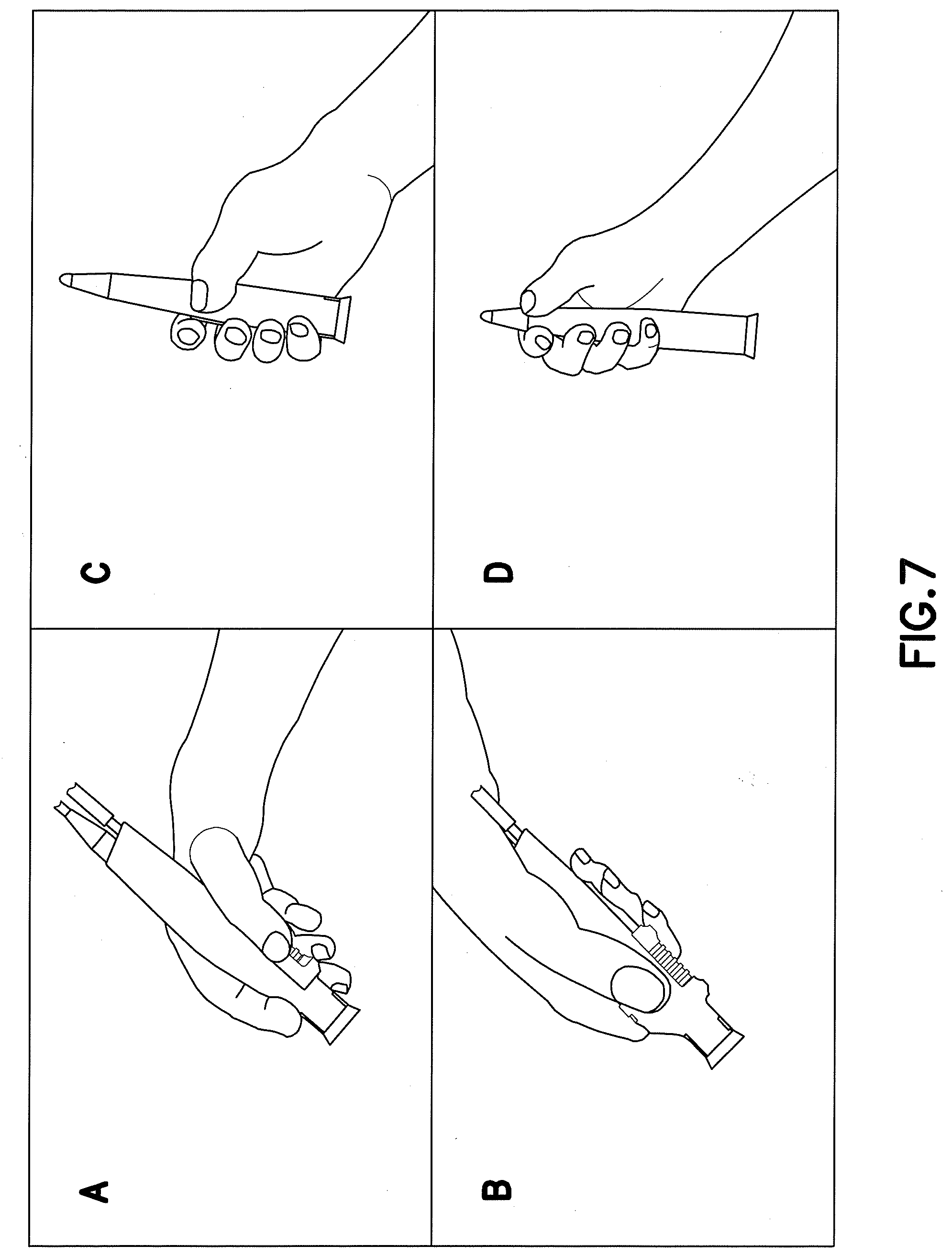
[0015] FIG. 7 provides various perspective views of different hand grip positions of the shaver handpiece of the fluid management system shown in FIG. 2.
DETAILED DESCRIPTION
[0016] Referring to FIG. 2, there is shown a perspective view of a fluid management system 100 incorporating features of the invention. Although the invention will be described with reference to the exemplary embodiments shown in the drawings, it should be understood that the invention can be embodied in many alternate forms of embodiments. In addition, any suitable size, shape or type of elements or materials could be used.
[0017] The fluid management system 100 includes a handpiece 102 and console 104. A shaver tubeset 106 is connected between the console 104 and the handpiece 102. The tubeset 106 is connected to the console 104 through a valve 105. Additionally, a power cable 108 is connected between the console 104 and the handpiece 102.
[0018] According to various exemplary embodiments, the console 104 may be a shaver console available from Stryker Corporation. However in alternate embodiments, any suitable type of shaver console, or variations thereof, may be provided.
[0019] Referring now also to FIG. 3, the shaver handpiece 102 comprises a housing 110 which surrounds a motor 112, a coupling 114, and a suction cannula 116. The handpiece 102 is configured such that an attachment 118 (such as a blade, for example) is removably connected to a front end of the handpiece 102. A motor shaft extending from the motor 112 comprises a pinion gear (driving) which is configured to engage with a driven gear on the coupling 114 to provide rotation to the attachment 118. According to various exemplary embodiments, the attachment 118 itself does not rotate, as the attachment 118 is a stationary component that accepts a disposable blade wherein an inner hub (of the attachment 118) engages with the coupling 114 to rotate or oscillate the inner disposable blade. A back end of the handpiece 102 is configured to receive a cable connector 120 of a cable 122 for connection to the motor 112. Also at the back end is an interface portion between the suction cannula 116 and the shaver tubeset 106. Additionally, activation buttons 124 are provided at the housing 110.
[0020] The fluid management system 100 provides for a slider electro-mechanical valve which includes a slider (or fluid control mechanism) 128 with a long magnet 130 which is captured inside and along a bottom portion of the slider 128. The slider 128 (and the magnet 130 along with the slider 128) is configured to move such that the magnet 130 slides above a hall effect sensor 132 which controls the (occluder) valve 105 to restrict the flow through the flexible suction tubeset 106.
[0021] Still referring to FIG. 3, the shaver handpiece with the slider suction controller valve is provided with a printed circuit board (PCB) and electronic circuitry configured such that the Hall Effect sensor 132 detects the slider magnet 130 location. Based on the slider location (magnet location), the occluder valve (or fluid occluding member) 105 with an actuator 136 restricts the suction flow proportionally through the shaver tubeset 106 (see also FIG. 4).
[0022] For example, as shown in FIG. 4 the occluder valve 105 is disposed within the shaver console 104 where the shaver tubeset 106 passes through the valve 105. The actuator 136 moves `in` and `out` to restrict the flow through the shaver tubeset 106. For example, as shown in FIG. 5 (which illustrates a top section view of the shaver tubeset passing though the occluder valve) the valve actuator 136 is configured to squeeze the tube 106 to restrict the flow (where unrestricted flow is shown in the left hand side of FIG. 5 and restricted flow is shown in the right hand side of FIG. 5).
[0023] The valve 105 may be a pinch valve manufactured by Resolution Air, for example (see FIG. 6). However in alternate embodiments, any suitable valve may be provided. In the example described above, the pinch valve 105 and the actuator 136 are controlled by a stepper motor of the console 104.
[0024] According to various exemplary embodiments of the invention, the slider electromechanical suction control can be placed away from the suction cannula pathway. This feature enables the user to have different hand grip positions. For example, as shown in FIG. 7 a variety of ergonomic handgrips such as a pen holding grip (see "A"), a grabbing grip (see "B"), a clasping downwards grip (see "C"), and a clasping grip (see "D"). Through research, the slider valve has the most comfortable handling and easily reachable configuration through the different types of ergonomic grips.
[0025] Technical effects of any one or more of the exemplary embodiments provide significant advantages over conventional configurations. For example, one advantage of the slider electro-mechanical valve is that it has no direct contact to the fluid passing through the suction cannula. Therefore, the cleaning and sanitizing of the suction cannula is much simpler and easily achieved. A tube brush can be used to clean straight through the suction cannula in much more effective and efficient way. The straight through design also enables a more efficient flow due to less turbulence and provide a better laminar flow. The straight through design also minimizes the chance of clogging during a procedure whereas conventional configuration a prone to this issue. Whereas in the conventional configurations, the suction control valve has limitations due to its location in the handpiece. For example, it is usually placed within the suction cannula of the handpiece shaver. In addition, the cleaning and sanitizing of the conventional handpieces is not simple and it could be a major factor for reuse the handpiece shaver. This is due to the difficulty of accessing certain places with a cleaning brush due to the inherent design of having a through hole on a cylindrical barrel and the angled suction path (for example see FIG. 1). Furthermore, the valve assembly with the conventional handpiece shaver requires a precise carefulness assembly to insure proper seal within the suction pathway.
[0026] Additional technical effects of any one or more of the exemplary embodiments provide for a fluid suction line that is remotely controlled by a magnetic sensor through a slider mechanism. Another technical effect of any one or more of the exemplary embodiments provide for a magnetic sensor to remotely control the fluid flow. Another technical effect of any one or more of the exemplary embodiments provide for ways to ergonomically handle the shaver handpiece shaver with easy access to the suction control slider valve.
[0027] Below are provided further descriptions of various non-limiting, exemplary embodiments. The below-described exemplary embodiments may be practiced in conjunction with one or more other aspects or exemplary embodiments. That is, the exemplary embodiments of the invention, such as those described immediately below, may be implemented, practiced or utilized in any combination (e.g., any combination that is suitable, practicable and/or feasible) and are not limited only to those combinations described herein and/or included in the appended claims.
[0028] In one exemplary embodiment, a fluid management assembly is disclosed. The fluid management assembly comprises: a handpiece; a slider based fluid control mechanism housed in the handpiece; and a fluid occluding member configured to be in communication with the fluid control mechanism; the fluid occluding member being separate from the handpiece.
[0029] A fluid management assembly as above, wherein the slider based fluid control mechanism comprises a magnet based sensor.
[0030] A fluid management assembly as above, wherein the fluid occluding member is disposed inside an equipment console separate from the handpiece.
[0031] A fluid management assembly as above, wherein the equipment console comprises an actuator.
[0032] A fluid management assembly as above, wherein the actuator is configured to squeeze a tube of the assembly to restrict flow.
[0033] A fluid management assembly as above, wherein the fluid occluding member comprises a valve.
[0034] A fluid management assembly as above, wherein fluid occluding member is. configured to have no direct contact with fluid passing through a suction cannula of the assembly.
[0035] A fluid management assembly as above, wherein the handpiece further comprises a suction cannula and a drive shaft, and wherein an entire length of the suction cannula is substantially concentric with the drive shaft.
[0036] A fluid management assembly as above, wherein the handpiece further comprises a motor and a printed circuit board, wherein the suction cannula is between the motor and the printed circuit board.
[0037] In another exemplary embodiment, a method is disclosed. The method comprises: providing a handpiece; connecting a slider based fluid control mechanism to the handpiece; and providing a fluid occluding member configured to be in communication with the fluid control mechanism, wherein the fluid occluding member is separate from the handpiece.
[0038] The method as above, wherein the slider based fluid control mechanism comprises a magnet based sensor.
[0039] The method as above, wherein the fluid occluding member is disposed inside an equipment console separate from the handpiece.
[0040] The method as above, wherein the equipment console comprises an actuator.
[0041] The method as above, wherein the actuator is configured to squeeze a tube of the assembly to restrict flow.
[0042] The method as above, wherein the fluid occluding member comprises a valve.
[0043] It should be understood that components of the invention can be operationally coupled or connected and that any number or combination of intervening elements can exist (including no intervening elements). The connections can be direct or indirect and additionally there can merely be a functional relationship between components.
[0044] It should be understood that the foregoing description is only illustrative of the invention. Various alternatives and modifications can be devised by those skilled in the art without departing from the invention. Accordingly, the invention is intended to embrace all such alternatives, modifications and variances which fall within the scope of the appended claims.
* * * * *
D00000
D00001
D00002
D00003
D00004
D00005
D00006
XML
uspto.report is an independent third-party trademark research tool that is not affiliated, endorsed, or sponsored by the United States Patent and Trademark Office (USPTO) or any other governmental organization. The information provided by uspto.report is based on publicly available data at the time of writing and is intended for informational purposes only.
While we strive to provide accurate and up-to-date information, we do not guarantee the accuracy, completeness, reliability, or suitability of the information displayed on this site. The use of this site is at your own risk. Any reliance you place on such information is therefore strictly at your own risk.
All official trademark data, including owner information, should be verified by visiting the official USPTO website at www.uspto.gov. This site is not intended to replace professional legal advice and should not be used as a substitute for consulting with a legal professional who is knowledgeable about trademark law.