Watch Clasp Capable Of Finely Adjusting Watch Strap Length
Yang; Rongguang ; et al.
U.S. patent application number 16/603660 was filed with the patent office on 2020-04-16 for watch clasp capable of finely adjusting watch strap length. This patent application is currently assigned to HUAWEI TECHNOLOGIES CO., LTD.. The applicant listed for this patent is HUAWEI TECHNOLOGIES CO., LTD.. Invention is credited to Jun Liu, Rongguang Yang, Bin Zhang, Menglong Zhao.
| Application Number | 20200113295 16/603660 |
| Document ID | / |
| Family ID | 63792183 |
| Filed Date | 2020-04-16 |
| United States Patent Application | 20200113295 |
| Kind Code | A1 |
| Yang; Rongguang ; et al. | April 16, 2020 |
WATCH CLASP CAPABLE OF FINELY ADJUSTING WATCH STRAP LENGTH
Abstract
A watch clasp with a finely adjustable watch strap length includes: a watch clasp sliding holder, located on a back surface of a watch clasp case; a sliding stop module, fixing the watch clasp sliding holder to the back surface of the watch clasp case through engagement, where the sliding holder can slide between the watch clasp case and the sliding stop module; a stop spring bar, fixed to the watch clasp case, and an unlock module, fixed to the watch clasp case where the unlock module is engaged with the sliding stop module, and the stop spring bar and the unlock module are respectively located on two sides of the sliding stop module; and an extension latch assembly, where one end of the extension latch assembly is fixed to the watch clasp case, and another end of the extension latch assembly is fixed to an elastic fine-adjusting assembly.
| Inventors: | Yang; Rongguang; (Shenzhen, CN) ; Liu; Jun; (Shenzhen, CN) ; Zhao; Menglong; (Shenzhen, CN) ; Zhang; Bin; (Shenzhen, CN) | ||||||||||
| Applicant: |
|
||||||||||
|---|---|---|---|---|---|---|---|---|---|---|---|
| Assignee: | HUAWEI TECHNOLOGIES CO.,
LTD. Shenzhen, Guangdong CN |
||||||||||
| Family ID: | 63792183 | ||||||||||
| Appl. No.: | 16/603660 | ||||||||||
| Filed: | April 24, 2017 | ||||||||||
| PCT Filed: | April 24, 2017 | ||||||||||
| PCT NO: | PCT/CN2017/081608 | ||||||||||
| 371 Date: | October 8, 2019 |
| Current U.S. Class: | 1/1 |
| Current CPC Class: | A44C 5/246 20130101; A44C 5/04 20130101; A44C 5/24 20130101 |
| International Class: | A44C 5/24 20060101 A44C005/24; A44C 5/04 20060101 A44C005/04 |
Foreign Application Data
| Date | Code | Application Number |
|---|---|---|
| Apr 14, 2017 | CN | 201710245369.2 |
Claims
1. A watch clasp for adjusting a watch strap length, comprising: a watch clasp sliding holder located on a back surface of a watch clasp case; a sliding stop module fixing the watch clasp sliding holder to the back surface of the watch clasp case through engagement, wherein the sliding holder slides between the watch clasp case and the sliding stop module; a stop spring bar fixed to the watch clasp case; an unlock module fixed to the watch clasp case, wherein the unlock module is engaged with the sliding stop module, and the stop spring bar and the unlock module are respectively located on two sides of the sliding stop module; and an extension latch assembly, wherein one end of the extension latch assembly is fixed to the watch clasp case, and the other another end of the extension latch assembly is fixed to an elastic fine-adjusting assembly.
2. The watch clasp according to claim 1, wherein the elastic fine-adjusting assembly includes a supporter, a slider, a spring bar shaft, a drive block, a fixing spring bar, and a leaf spring; the leaf spring is embedded into a connection port on the drive block, and the fixing spring bar fixes the drive block to the supporter, and the fixing spring bar fixes the slider to the supporter, the spring bar shaft is fixed to the slider, and the spring bar shaft is configured to connect to a watch strap.
3. The watch clasp according to claim 1, wherein the sliding stop module is engaged with the unlock module, and by pressing two ends of the unlock module, a spring in the unlock module drives a main toggle arm and the main toggle arm drives an auxiliary toggle arm that is of the sliding stop module and that is flexibly connected to the main toggle arm, so that two fixing poles of the sliding stop module move towards each other, to unlock the watch clasp sliding holder.
4. The watch clasp according to claim 1, wherein the stop spring bar is fixed, by using an elastic device, to a fixing hole disposed on the watch clasp case, wherein a size of the fixing hole is the same as a size of the elastic device, and the stop spring bar adjusts a length of the stop spring bar by using the elastic device.
5. The watch clasp according to claim 2, wherein the fixing spring bar fixes the drive block and the leaf spring to the supporter, the slider is flexibly connected to the supporter, the fixing spring bar, the drive block, and the leaf spring are all located within a coverage range of the slider, the slider slides along a groove reserved on the supporter, and the slider adjusts a sliding position by using the leaf spring.
6. The watch clasp according to claim 3, wherein the sliding stop module is engaged with the watch clasp sliding holder, a fixing module of the sliding stop module is provided with a notch, a position at which the watch clasp sliding holder is engaged with the sliding stop module is provided with a corresponding notch, and the notch is used to remove the connected sliding stop module
7. The watch clasp according to claim 6, wherein the notch is semicircular.
8. The watch clasp according to claim 3, wherein the sliding stop module comprises an auxiliary toggle arm, a spring, and a sliding stop module enclosure, the auxiliary toggle arm resets by using the spring, and the fixing pole is a part of the auxiliary toggle arm.
9. The watch clasp according to claim 8, wherein the fixing pole and the auxiliary toggle arm are detachably connected.
10. The watch clasp according to claim 3, wherein the unlock module comprises a main toggle arm, a spring and an unlock module enclosure; and the main toggle arm resets by using the spring.
11. The watch clasp according to claim 1, wherein the extension latch assembly comprises a first extension fastening component, a second extension fastening component, and a fixing spring bar shaft; a size of one end of the first extension fastening component is the same as a size of a groove at one end of the second extension fastening component the one end of the first extension fastening component and the one end of the second extension fastening component are connected by using a rotating shaft, another end of the first extension fastening component is connected to the elastic fine-adjusting assembly, another end of the second extension fastening component is connected to the watch clasp case, rotation between the first extension fastening component and the second extension fastening component forms any angle, and the fixing spring bar shaft is configured to fix the second extension fastening component to the watch clasp case.
12. A watch strap, comprising a watch clasp that adjusts a length of the watch strap, the watch clasp including: a watch clasp sliding holder, located on a back surface of a watch clasp case; a sliding stop module, fixing the watch clasp sliding holder to the back surface of the watch clasp case through engagement, wherein the sliding holder slides between the watch clasp case and the sliding stop module; a stop spring bar, fixed to the watch clasp case, and an unlock module, fixed to the watch clasp case, wherein the unlock module is engaged with the sliding stop module, and the stop spring bar and the unlock module are respectively located on two sides of the sliding stop module; and an extension latch assembly, wherein one end of the extension latch assembly is fixed to the watch clasp case, and another end of the extension latch assembly is fixed to an elastic fine-adjusting assembly.
13. A watch, comprising a watch strap and a watch clasp connected to the watch strap, the watch clasp adjusting a length of the watch strap, and the watch clasp including: a watch clasp sliding holder, located on a back surface of a watch clasp case; a sliding stop module, fixing the watch clasp sliding holder to the back surface of the watch clasp case through engagement, wherein the sliding holder slides between the watch clasp case and the sliding stop module; a stop spring bar, fixed to the watch clasp case, and an unlock module, fixed to the watch clasp case, wherein the unlock module is engaged with the sliding stop module, and the stop spring bar and the unlock module are respectively located on two sides of the sliding stop module; and an extension latch assembly, wherein one end of the extension latch assembly is fixed to the watch clasp case, and another end of the extension latch assembly is fixed to an elastic fine-adjusting assembly.
Description
[0001] This application claims priority to Chinese Patent Application No. 201710245369.2, filed with the Chinese Patent Office on Apr. 14, 2017, and entitled "WATCH CLASP CAPABLE OF ADJUSTING LENGTH", which is incorporated herein by reference in its entirety.
TECHNICAL FIELD
[0002] This application relates to a watch clasp, and in particular, to a watch clasp capable of finely adjusting a watch strap length.
BACKGROUND
[0003] Currently, a watch is adapted to a wrist size of a wearer by adjusting a length of a watch strap. However, the wrist size of the wearer changes with an environment. For example, the wrist size increases after the wearer plays sports. Therefore, the length of the watch needs to be adjusted at any time to keep the wrist comfortable whenever and wherever possible. A length of a steel watch strap is ususally adjusted by increasing or reducing a quantity of balls of the watch strap, and both the increase and reduction of the quantity of the balls of the watch strap require a special-purpose tool to adjust tightness of wearing of the watch strap.
[0004] At present, a special-purpose tool used for separating a watch strap needs to be used when lengths of watch straps of most steel watch straps are adjusted by increasing or reducing quantities of ball of the watch straps. This is inconvenient for adjusting a watch strap length and wearing tightness during sports time whenever and wherever possible. In addition, a ball of a common steel watch strap has a relatively large width, that is, at least 3 mm, making it impossible to reach much smaller millimeter-level length fine adjustment by adjusting the length of the watch strap by changing a quantity of balls of the watch strap.
[0005] Methods in an existing solution of adjusting lengths of watch straps are all performing adjustment by increasing or reducing quantities of balls of the watch straps. It is very inconvenient to use the methods, and millimeter-level fine adjustment of a watch strap length cannot be implemented conveniently whenever and wherever possible without using any tool.
SUMMARY
[0006] Embodiments of this application provide a watch clasp capable of finely adjusting a watch strap length, to conveniently implement millimeter-level fine adjustment of a length of a watch strap whenever and wherever possible without using any tool to increase or reduce the length of the watch strap, thereby adjusting tightness of wearing of the watch strap whenever and wherever possible.
[0007] A first aspect of the embodiments of this application provides a watch clasp capable of finely adjusting a watch strap length, including: a watch clasp sliding holder 102, located on a back surface of a watch clasp case 101; a sliding stop module 104, fixing the watch clasp sliding holder 102 to the back surface of the watch clasp case 101 through engagement, where the sliding holder 102 can slide between the watch clasp case 101 and the sliding stop module 104; a stop spring bar 103, fixed to the watch clasp case 101, and an unlock module 105, fixed to the watch clasp case 101, where the unlock module 105 is engaged with the sliding stop module 104, and the stop spring bar 103 and the unlock module 105 are respectively located on two sides of the sliding stop module 104; and an extension latch assembly, where one end of the extension latch assembly 106 is fixed to the watch clasp case 101, and the other end of the extension latch assembly 106 is fixed to an elastic fine-adjusting assembly 107. The embodiments of this application provide a watch clasp capable of finely adjusting a watch strap length, to implement millimeter-level fine adjustment of a length of a watch strap whenever and wherever possible to increase or reduce the length of the watch strap, thereby adjusting tightness of wearing of the watch strap.
[0008] In a possible design, in a first implementation of the first aspect of the embodiments of this application, the elastic fine-adjusting assembly 107 includes: a supporter 108, a slider 109, a spring bar shaft 110, a drive block 111, a fixing spring bar 112, and a leaf spring 113. The leaf spring 113 is embedded into a connection port reserved on the drive block 111. The fixing spring bar 112 fixes the drive block 111 to the supporter 108. The fixing spring bar 112 fixes the slider 109 to the supporter 108. The spring bar shaft 110 is fixed to the slider 109. The spring bar shaft 110 is configured to connect to a watch strap. The embodiments of this application describe in detail the elastic fine-adjusting assembly, thereby increasing reliability and integrity of the embodiments of this application.
[0009] In a possible design, in a second implementation of the first aspect of the embodiments of this application, including: the sliding stop module 104 is engaged with the unlock module 105. By pressing two ends of the unlock module 105, a spring in the unlock module 105 drives a main toggle arm 114, and the main toggle arm 114 drives an auxiliary toggle arm 115 that is of the sliding stop module 104 and that is flexibly connected to the main toggle arm 114, so that two fixing poles 116 of the sliding stop module 104 move towards each other, to unlock the watch clasp sliding holder 102. The embodiments of this application describe in detail a connection manner of the sliding stop module and the unlock module, thereby increasing reliability and integrity of the embodiments of this application.
[0010] In a possible design, in a third implementation of the first aspect of the embodiments of this application, including: the stop spring bar 103 is fixed, by using an elastic device, to a fixing hole 1011 disposed on the watch clasp case 101. A size of the fixing hole 1011 is the same as a size of the elastic device. The stop spring bar 103 can adjust a length of the stop spring bar 103 by using the elastic device. The embodiments of this application describe in detail a fixing manner of the stop spring bar, thereby increasing reliability and integrity of the embodiments of this application.
[0011] In a possible design, in a fourth implementation of the first aspect of the embodiments of this application, including: the fixing spring bar 112 fixes the drive block 111 and the leaf spring 113 to the supporter 108. The slider 109 is flexibly connected to the supporter 108. The fixing spring bar 112, the drive block 111, and the leaf spring 113 are all located within a coverage range of the slider 109. The slider 109 can slide along a groove reserved on the supporter 108 the supporter. The slider 109 can adjust a sliding position by using the leaf spring 113. The embodiments of this application describe in detail a connection relationship between the components in the elastic fine-adjusting assembly, thereby increasing operability of the embodiments of this application.
[0012] In a possible design, in a fifth implementation of the first aspect of the embodiments of this application, including: the sliding stop module 104 is engaged with the watch clasp sliding holder 102. A fixing module of the sliding stop module 104 is provided with a notch 117. A position at which the watch clasp sliding holder 102 is engaged with the sliding stop module 104 is provided with a corresponding notch 117. The notch 117 is used to remove the connected sliding stop module 104. The embodiments of this application describe in detail a specific connection relationship between the sliding stop module and the watch clasp sliding holder, thereby making the embodiments of this application more complete.
[0013] In a possible design, in a sixth implementation of the first aspect of the embodiments of this application, including: the notch 117 is semicircular. The embodiments of this application limit the shape of the notch disposed on the watch clasp sliding holder, thereby increasing operability of the embodiments of this application.
[0014] In a possible design, in a seventh implementation of the first aspect of the embodiments of this application, the sliding stop module 104 includes an auxiliary toggle arm 115, a spring 118, and a sliding stop module enclosure 119. The auxiliary toggle arm 115 resets by using the spring 118. The fixing pole 116 is a part of the auxiliary toggle arm 115. The embodiments of this application describe in detail a specific structure of the components of the sliding stop module, thereby increasing operability of the embodiments of this application.
[0015] In a possible design, in an eighth implementation of the first aspect of the embodiments of this application, including: the fixing pole 116 and the auxiliary toggle arm 115 are detachably connected. The embodiments of this application limit a connection relationship between the fixing pole and the auxiliary toggle arm, thereby increasing operability of the embodiments of this application.
[0016] In a possible design, in a ninth implementation of the first aspect of the embodiments of this application, including: the unlock module 105 includes a main toggle arm 114, a spring 120, and an unlock module enclosure 121. The main toggle arm 114 resets by using the spring 120. The embodiments of this application describe in detail a specific structure of the components of the unlock module, thereby increasing operability of the embodiments of this application.
[0017] In a possible design, in a tenth implementation of the first aspect of the embodiments of this application, including: the extension latch assembly 106 includes a first extension fastening component 1061, a second extension fastening component 1062, and a fixing spring bar shaft 1063. A size of one end of the first extension fastening component 1061 is the same as a size of a groove reserved at one end of the second extension fastening component 1062, and the one end of the first extension fastening component 1061 and the one end of the second extension fastening component 1062 are connected by using a rotating shaft. The other end of the first extension fastening component 1061 is connected to an elastic fine-adjusting assembly 107. The other end of the second extension fastening component 1062 is connected to the watch clasp case 101. Rotation between the first extension fastening component 1061 and the second extension fastening component 1062 can form any angle. The fixing spring bar shaft 1063 is configured to fix the second extension fastening component 1062 to the watch clasp case 101. The embodiments of this application describe in detail a specific structure of the components of the extension latch assembly, thereby increasing operability of the embodiments of this application.
[0018] A second aspect of the embodiments of this application provides a watch strap, including the watch clasp according to any one of the first aspect or the first to the tenth implementation of the first aspect according to this application. The embodiments of this application provide the watch strap including the watch clasp, thereby increasing reliability of the embodiments of this application.
[0019] A third aspect of the embodiments of this application provides a watch, including the watch clasp according to any one of the first aspect or the first to the tenth implementation of the first aspect according to this application that is connected to a watch strap. The embodiments of this application provide the watch including the watch clasp, thereby increasing reliability of the embodiments of this application.
[0020] In the technical solution provided in the embodiments of this application, a watch clasp capable of finely adjusting a watch strap length is provided. The watch clasp capable of finely adjusting a watch strap length includes: a watch clasp sliding holder 102, located on a back surface of a watch clasp case 101; a sliding stop module 104, fixing the watch clasp sliding holder 102 to the back surface of the watch clasp case 101 through engagement, where the sliding holder 102 can slide between the watch clasp case 101 and the sliding stop module 104; a stop spring bar 103, fixed to the watch clasp case 101, and an unlock module 105, fixed to the watch clasp case 101, where the unlock module 105 is engaged with the sliding stop module 104, and the stop spring bar 103 and the unlock module 105 are respectively located on two sides of the sliding stop module 104; and an extension latch assembly, where one end of the extension latch assembly 106 is fixed to the watch clasp case 101, and the other end of the extension latch assembly 106 is fixed to an elastic fine-adjusting assembly 107. The embodiments of this application provide the watch clasp capable of finely adjusting a watch strap length, to conveniently implement millimeter-level fine adjustment of a length of a watch strap whenever and wherever possible without using any tool to increase or reduce the length of the watch strap, thereby adjusting tightness of wearing of the watch strap whenever and wherever possible.
BRIEF DESCRIPTION OF DRAWINGS
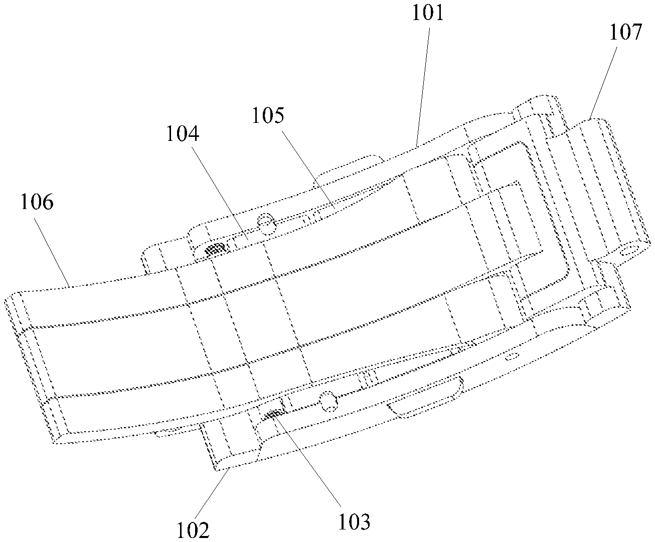
[0021] FIG. 1 is a schematic diagram of a back surface of a watch clasp in a closed state according to this application;
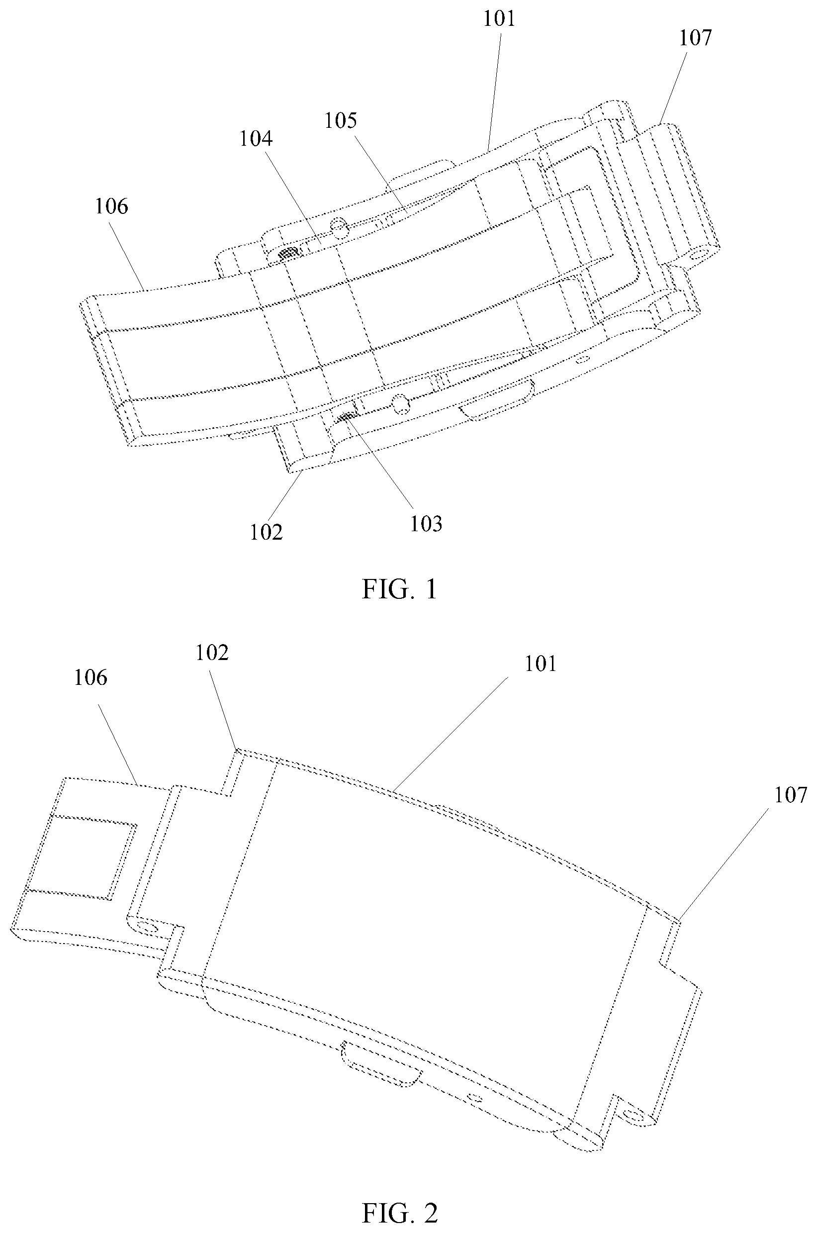
[0022] FIG. 2 is a schematic diagram of a front surface of a watch clasp in a closed state according to this application;
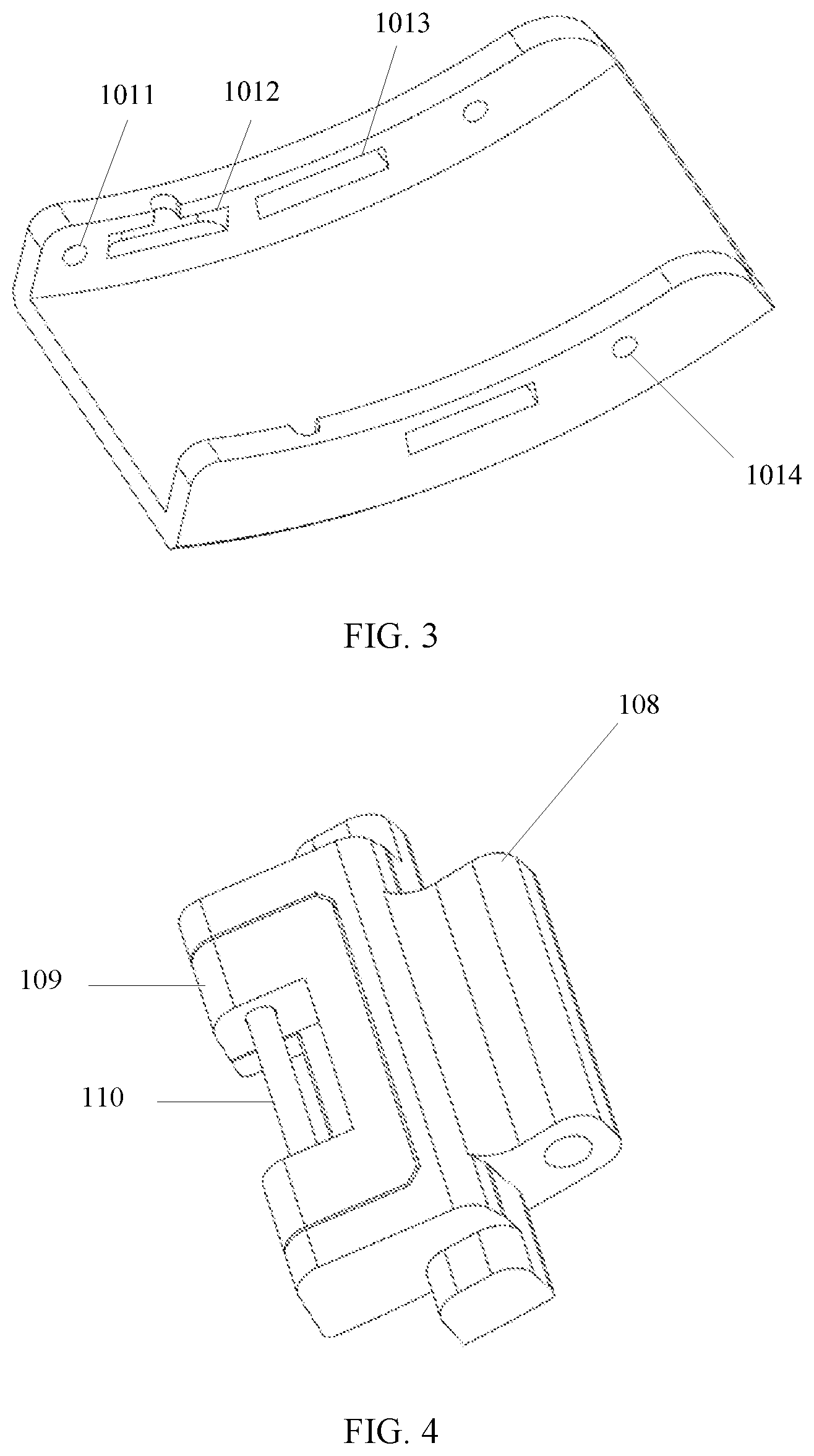
[0023] FIG. 3 is a schematic diagram of a watch clasp case of a watch clasp according to this application;
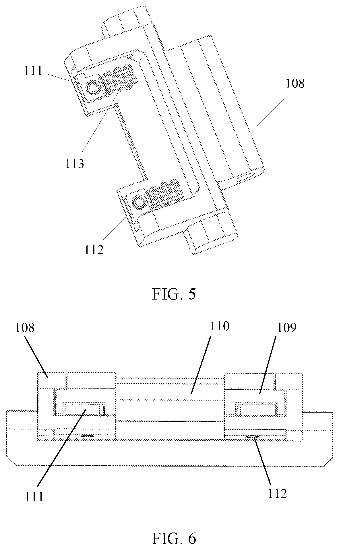
[0024] FIG. 4 is a schematic diagram of an elastic fine-adjusting assembly of a watch clasp according to this application;
[0025] FIG. 5 is a schematic diagram of assembly of some components in an elastic fine-adjusting assembly according to this application;
[0026] FIG. 6 is a side view of an elastic fine-adjusting assembly according to this application;
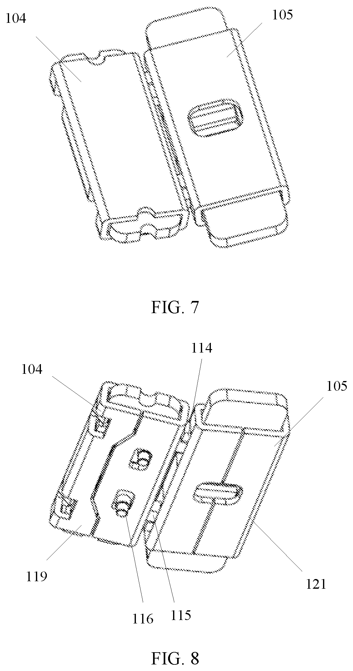
[0027] FIG. 7 is a schematic diagram of connection between a sliding stop module and an unlock module according to this application;
[0028] FIG. 8 is another schematic diagram of connection between a sliding stop module and an unlock module according to this application;
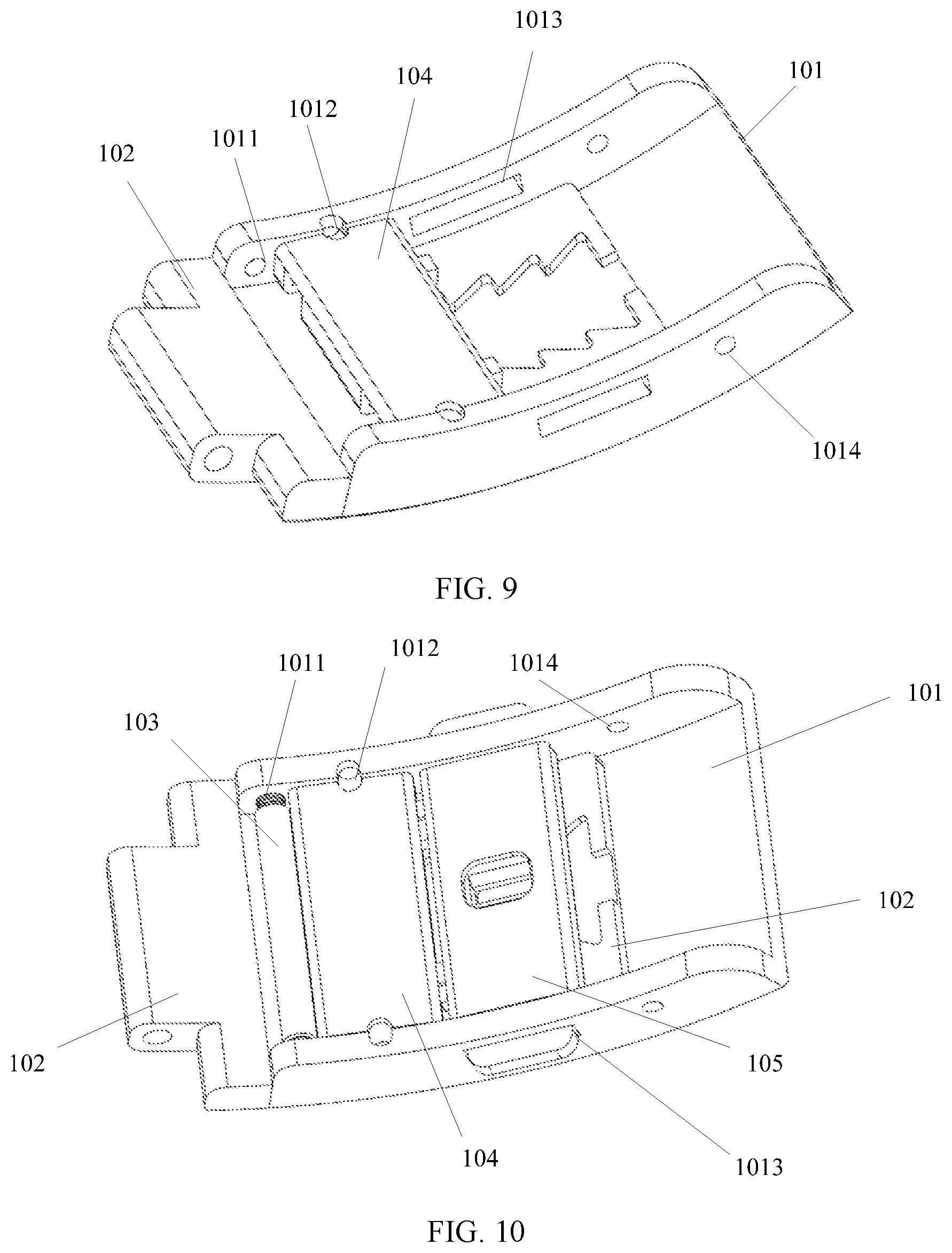
[0029] FIG. 9 is a schematic diagram of assembly of a sliding stop module according to this application;
[0030] FIG. 10 is a schematic diagram of assembly of a sliding stop module and an unlock module according to this application;
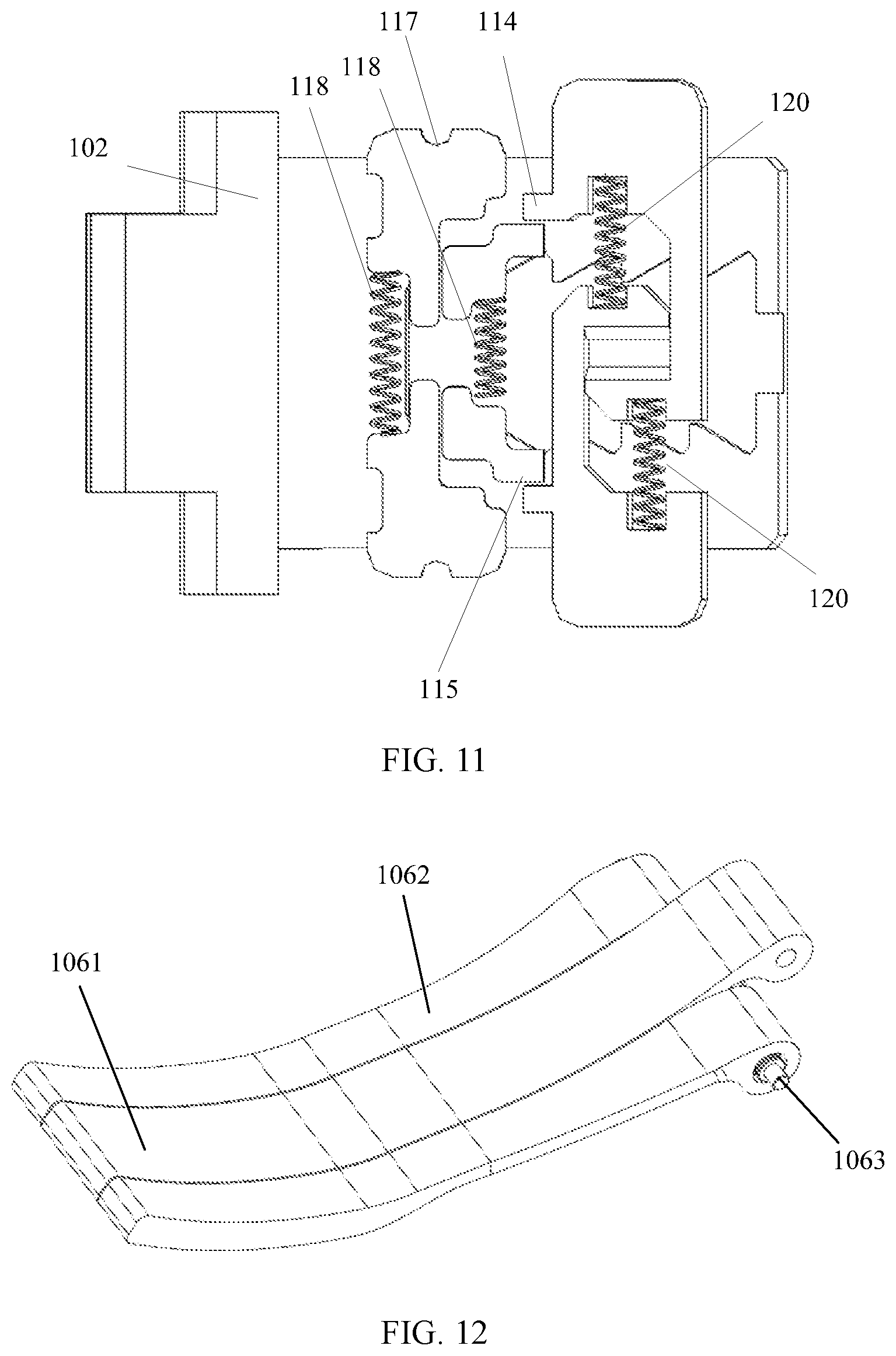
[0031] FIG. 11 is a schematic diagram of connection of some components of a sliding stop module and an unlock module on a watch clasp sliding holder according to this application;
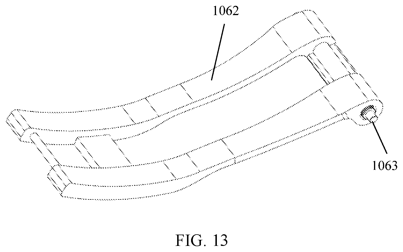
[0032] FIG. 12 is a schematic diagram of assembly of an extension latch assembly of a watch clasp according to this application; and
[0033] FIG. 13 is a schematic diagram of assembly of some components in an extension latch assembly of a watch clasp according to this application.
DESCRIPTION OF EMBODIMENTS
[0034] Embodiments of this application provide a watch clasp capable of finely adjusting a watch strap length, to conveniently implement millimeter-level fine adjustment of a length of a watch strap whenever and wherever possible without using any tool to increase or reduce the length of the watch strap, thereby adjusting tightness of wearing of the watch strap whenever and wherever possible.
[0035] To make persons skilled in the art understand the solutions in this application better, the following describes the embodiments of this application with reference to the accompanying drawings in the embodiments of this application.
[0036] In the specification, claims, and accompanying drawings of this application, the terms "first", "second", "third", "fourth", and so on (if existent) are intended to distinguish between similar objects but do not necessarily indicate a specific order or sequence. It should be understood that the data termed in such a way are interchangeable in proper circumstances so that the embodiments of the present invention described herein can be implemented in other orders than the order illustrated or described herein. Moreover, the terms "include", "have" and any other variants mean to cover the non-exclusive inclusion, for example, a process, method, system, product, or device that includes a list of steps or units is not necessarily limited to those steps or units, but may include other steps or units not expressly listed or inherent to such a process, method, product, or device.
[0037] FIG. 1 is a schematic diagram of a back surface of a watch clasp in a closed state. FIG. 2 is a schematic diagram of a front surface of a watch clasp in a closed state according to this application. The following describes in detail a watch clasp with reference to the schematic diagrams.
[0038] As shown in FIG. 1 and FIG. 2, the watch clasp includes a watch clasp case 101, a watch clasp sliding holder 102, a stop spring bar 103, a sliding stop module 104, an unlock module 105, an extension latch assembly 106, and an elastic fine-adjusting assembly 107.
[0039] The watch clasp sliding holder 102 is located on a back surface of the watch clasp case 101.
[0040] The sliding stop module 104 fixes the watch clasp sliding holder 102 to the back surface of the watch clasp case 101 through engagement. The sliding holder 102 can slide between the watch clasp case 101 and the sliding stop module 104.
[0041] The stop spring bar 103 is fixed to the watch clasp case 101. The unlock module 105 is fixed to the watch clasp case 101, and the unlock module 105 is engaged with the sliding stop module 104. The stop spring bar 103 and the unlock module 105 are respectively located on two sides of the sliding stop module 104.
[0042] One end of the extension latch assembly 106 is fixed to the watch clasp case 101, and the other end of the extension latch assembly 106 is fixed to the elastic fine-adjusting assembly 107.
[0043] For example, the watch clasp case 101 is provided with fixing holes, used to fix another component of the watch clasp. As shown in FIG. 3, the watch strap case 101 is provided with a fixing hole 1011, a fixing hole 1012, a fixing hole 1013, and a fixing hole 1014 at positions shown in the figure. The fixing hole 1011 is used to fix the stop spring bar 103 to the watch clasp case 101, the fixing hole 1011 is a circular slot, and a size and a depth of the fixing hole 1011 are adapted to spring structures at two ends of the stop spring bar 103. The fixing hole 1012 is used to fix the sliding stop module 104 to the watch clasp case 101, and the fixing hole 1012 is a rectangle slot. In addition, a through slot is disposed on a side of the rectangle slot adjacent to the back surface of the watch clasp case 101, and the through slot is used to remove the fixed sliding stop module 104 by using a special-purpose tool. A size and a depth of the fixing hole 1012 are adapted to an auxiliary toggle arm 115 of the sliding stop module 104. Optionally, the through slot is semicircular. The fixing hole 1013 is used to fix the unlock module 105 to the watch clasp case 101, the fixing hole 1013 is a rectangle slot, and a size and a depth of the fixing hole 1013 are adapted to a main toggle arm 114 of the unlock module 105. The fixing hole 1014 is used to fix the elastic fine-adjusting assembly 107 to the watch clasp case 101, the fixing hole 1014 is a circular slot, and a size and a depth of the fixing hole 1014 are adapted to a structure of a fixing spring bar shaft 1063 of the extension latch assembly 106.
[0044] It can be understood that, the size, the shape and the depth of the fixing hole can be set based on an actual case. This is not specifically limited herein.
[0045] FIG. 4 is a schematic diagram of an elastic fine-adjusting assembly of a watch clasp according to this application. FIG. 5 is a schematic diagram of assembly of some components in an elastic fine-adjusting assembly according to this application. FIG. 6 is a side view of an elastic fine-adjusting assembly according to this application.
[0046] As shown in FIG. 4 and FIG. 5, the elastic fine-adjusting assembly 107 includes: a supporter 108, a slider 109, a spring bar shaft 110, a drive block 111, a fixing spring bar 112, and a leaf spring 113. With reference to FIG. 6, the supporter 108 is provided with a groove at a position at which the slider 109 is installed. The slider 109 slides by using the groove. A size and a depth of the groove may be set based on an actual case. This is not specifically limited herein. The drive block 111 is fixed right below of the slider 109, and the drive block 111 is flush with a side surface of the slider 109 and that of the supporter 108.
[0047] As shown in FIG. 5, the leaf spring 113 is embedded into a reserved connection port on the drive block 111, and the leaf spring 113 may be deformed along a sliding direction of the slider 109. That is, the slider 109 slides in a direction of the groove of the supporter 108 by using the deformation of the leaf spring 113. The fixing spring bar 112 fixes the drive block 111 to the supporter 108, so that the slider 109 is fixed into the groove of the supporter 108. The fixing spring bar 112 fixes the slider 109 to the supporter 108. The spring bar shaft 110 is fixed to the slider 109, and the spring bar shaft (110) is configured to connect to a watch strap.
[0048] For example, the fixing spring bar 112 fixes the drive block 111 and the leaf spring 113 to the supporter 108. The slider 109 is flexibly connected to the supporter 108, and the slider 109 slides in the groove disposed on the supporter 108. The fixing spring bar 112, the drive block 111, and the leaf spring 113 are all located within a coverage range of the slider 109. The slider 109 may slide along the groove reserved in the supporter 108 the supporter, and the slider 109 can adjust a sliding position by using the leaf spring 113.
[0049] FIG. 7 is a schematic diagram of connection between a sliding stop module and an unlock module according to this application. FIG. 8 is another schematic diagram of connection between a sliding stop module and an unlock module according to this application. FIG. 9 is a schematic diagram of assembly of a sliding stop module according to this application. FIG. 10 is a schematic diagram of assembly of a sliding stop module and an unlock module according to this application.
[0050] As shown in FIG. 7 and FIG. 8, the sliding stop module 104 is engaged with the unlock module 105. In a manner of pressing two ends of the unlock module 105, a spring in the unlock module 105 drives the main toggle arm 114, and the main toggle arm 114 drives the auxiliary toggle arm 115 that is of the sliding stop module 104 and that is flexibly connected to the main toggle arm 114, so that two fixing poles 116 of the sliding stop module 104 move towards each other, and the watch clasp sliding holder 102 can slide back and forth.
[0051] As shown in FIG. 9, when the sliding stop module 104 is engaged with the watch clasp case 101 by using the fixing hole 1012, the watch clasp sliding holder 102 is located between the sliding stop module 104 and the watch clasp case 101, and a sawtooth shape groove structure is disposed on a middle part of the watch clasp sliding holder 102. The fixing poles 116 of the sliding stop module 104 are away from each other. Each fixing pole 116 is engaged with the sawtooth shape groove structure. A position of the watch clasp sliding holder 102 is fixed.
[0052] Optionally, the sawtooth shape groove structure of the watch clasp sliding holder 102 is divided into five adjustable levels, and an adjustable length of each level is 2.08 millimeters. A quantity of the adjustable levels and the adjustable length of each adjustable level may further be set based on an actual case. A specific length is not limited herein.
[0053] As shown in FIG. 10, the sliding stop module 104 is engaged with the watch clasp case 101 by using the fixing hole 1012, the unlock module 105 is engaged with the watch clasp case 101 by using the fixing hole 1013, and the stop spring bar 103 is engaged with the watch clasp case 101 by using the fixing hole 1011. When the watch clasp sliding holder 102 is located between the sliding stop module 104 and the watch clasp case 101, the auxiliary toggle arm 115 of the sliding stop module 104 is located on an internal side of the main toggle arm 114 of the unlock module 105. When the unlock module is pressed, the two main toggle arms 114 move towards each other, to drive the auxiliary toggle arm 115 that is connected to the main toggle arm 114 to move closer, and the two fixing poles 116 that are connected to the auxiliary toggle arm 115 move towards each other, so that the two fixing poles 116 can slide in the sawtooth shape groove structure.
[0054] Optionally, the stop spring bar 103 is fixed, by using an elastic device, to the fixing hole 1011 disposed on the watch clasp case 101. The size of the fixing hole 1011 and a size of the elastic device are the same. The stop spring bar 103 can adjust a length of the stop spring bar 103 by using the elastic device. It can be understood that, a diameter size of the elastic device of the stop spring bar 103 is the same as a diameter size of the fixing hole 1011, so that the stop spring bar 103 can be firmly fixed to the watch clasp case 101.
[0055] It should be noted that, the sliding stop module 104 is engaged with the watch clasp sliding holder 102, a fixing module of the sliding stop module 104 is provided with a notch 117, and a position at which the watch clasp sliding holder 102 is engaged with the sliding stop module 104 is provided with a corresponding notch 117. The notch 117 is used to remove the sliding stop module 104 that is already engaged with the watch clasp case 101. Optionally, the notch 117 is semicircular, or may be further in another shape. This is not specifically limited herein.
[0056] Optionally, the sliding stop module 104 includes an auxiliary toggle arm 115, a spring 118, and a sliding stop module enclosure 119. As shown in FIG. 11, auxiliary toggle arm 115 resets by using the spring 118. The fixing pole 116 is a part of the auxiliary toggle arm 115.
[0057] Optionally, the unlock module 105 includes a main toggle arm 114, a spring 120, and an unlock module enclosure 121. The main toggle arm 114 resets by using the spring 120.
[0058] Optionally, the fixing pole 116 and the auxiliary toggle arm 115 are detachably connected. A specific detachable connection manner may be threaded connection or engagement, or may further be another detachable connection manner. This is not specifically limited herein.
[0059] For example, FIG. 11 is a schematic diagram of connection of some components that are of a sliding stop module and an unlock module and that are on a watch clasp sliding holder according to this application. As shown in FIG. 11, an auxiliary toggle arm 115 of the sliding stop module 104 is connected to a main toggle arm 114 of the unlock module 105 in a manner shown in the figure. The main toggle arm 114 of the unlock module 105 resets by using a spring 120 of the unlock module 105. When the main toggle arm 114 is pressed, two ends of a watch clasp case 101 are exposed, and the spring 120 is compressed. When the main toggle arm 114 is not pressed, the spring 120 extends, thereby driving the main toggle arm 114 to get back to a set initial position. When the auxiliary toggle arm 115 is driven by the main toggle arm 114, a spring 118 of the sliding stop module 104 is compressed. When the main toggle arm 114 is not pressed, the main toggle arm 114 resets, the auxiliary toggle arm 115 is not interfered with by external force anymore, and the spring 118 extends, thereby driving the auxiliary toggle arm 115 to get back to a set initial position and implementing a resetting function of the auxiliary toggle arm 115. When the main toggle arm 114 is pressed, two ends of a watch clasp case 101 are exposed, the auxiliary toggle arm 115 moves closer, and two fixing poles 116 (not shown in FIG. 11) that are located on the auxiliary toggle arm 115 move towards each other, so that the watch clasp sliding holder 102 releases a lock state, to implement a sliding function.
[0060] FIG. 12 is a schematic diagram of assembly of an extension latch assembly of a watch clasp according to this application. FIG. 13 is a schematic diagram of assembly of some components in an extension latch assembly of a watch clasp according to this application.
[0061] Optionally, the extension latch assembly 106 includes a first extension fastening component 1061, a second extension fastening component 1062, and a fixing spring bar shaft 1063. A size of one end of the first extension fastening component 1061 is the same as a size of a groove reserved at one end of the second extension fastening component 1062, and the one end of the first extension fastening component 1061 and the one end of the second extension fastening component 1062 are connected by using a rotating shaft The other end of the first extension fastening component 1061 is connected to an elastic fine-adjusting assembly 107, the other end of the second extension fastening component 1062 is connected to a watch clasp case 101, and rotation between the first extension fastening component 1061 and the second extension fastening component 1062 can form any angle. The fixing spring bar shaft 1063 is configured to fix the second extension fastening component 1062 to the watch clasp case 101.
[0062] For example, with reference to FIG. 11 and FIG. 12, a size of one end of the first extension fastening component 1061 of the extension latch assembly 106 is the same as the size of the groove reserved at one end of the second extension fastening component 1062, and the one end of the first extension fastening component 1061 and the one end of the second extension fastening component 1062 are connected by using the rotating shaft. The rotating shaft is shown in FIG. 13. The rotating shaft and the fixing spring bar shaft 1063 are respectively located at two ends of the second extension fastening component 1062. The extension latch assembly 106 fixes a segment of the second extension fastening component 1062 to the watch clasp case 101 by using the fixing spring bar shaft 1063.
[0063] The foregoing embodiments are merely intended for describing the technical solutions of this application, but not for limiting this application. Although this application is described in detail with reference to the foregoing embodiments, persons of ordinary skill in the art should understand that they may still make modifications to the technical solutions described in the foregoing embodiments or make equivalent replacements to some technical features thereof, without departing from the spirit and scope of the technical solutions of the embodiments of this application.
* * * * *
D00000
D00001
D00002
D00003
D00004
D00005
D00006
D00007
XML
uspto.report is an independent third-party trademark research tool that is not affiliated, endorsed, or sponsored by the United States Patent and Trademark Office (USPTO) or any other governmental organization. The information provided by uspto.report is based on publicly available data at the time of writing and is intended for informational purposes only.
While we strive to provide accurate and up-to-date information, we do not guarantee the accuracy, completeness, reliability, or suitability of the information displayed on this site. The use of this site is at your own risk. Any reliance you place on such information is therefore strictly at your own risk.
All official trademark data, including owner information, should be verified by visiting the official USPTO website at www.uspto.gov. This site is not intended to replace professional legal advice and should not be used as a substitute for consulting with a legal professional who is knowledgeable about trademark law.