Active Stance Last
Dirsa; David Joseph ; et al.
U.S. patent application number 16/598759 was filed with the patent office on 2020-04-16 for active stance last. The applicant listed for this patent is The North Face Apparel Corp.. Invention is credited to Alexander Dardinski, David Joseph Dirsa, Tadd Nicholas Smith.
| Application Number | 20200113279 16/598759 |
| Document ID | / |
| Family ID | 68393077 |
| Filed Date | 2020-04-16 |


| United States Patent Application | 20200113279 |
| Kind Code | A1 |
| Dirsa; David Joseph ; et al. | April 16, 2020 |
ACTIVE STANCE LAST
Abstract
An article of footwear, a method of making the footwear, and an active last for forming the footwear are described. An example active last may comprise a heel portion disposed at a first end. The active last may comprise a forefoot portion disposed adjacent a second end, opposite the first end. At least a portion of the forefoot portion may have a curvilinear shape that curves upwardly from a horizontal axis to model an active stance.
| Inventors: | Dirsa; David Joseph; (Brentwood, NH) ; Dardinski; Alexander; (Newburyport, MA) ; Smith; Tadd Nicholas; (Rye, NH) | ||||||||||
| Applicant: |
|
||||||||||
|---|---|---|---|---|---|---|---|---|---|---|---|
| Family ID: | 68393077 | ||||||||||
| Appl. No.: | 16/598759 | ||||||||||
| Filed: | October 10, 2019 |
Related U.S. Patent Documents
| Application Number | Filing Date | Patent Number | ||
|---|---|---|---|---|
| 62744799 | Oct 12, 2018 | |||
| Current U.S. Class: | 1/1 |
| Current CPC Class: | A43B 1/0018 20130101; A43B 13/14 20130101; A43B 13/141 20130101; A43D 3/02 20130101; A43B 7/144 20130101; A43B 13/02 20130101; A43B 13/181 20130101 |
| International Class: | A43B 13/18 20060101 A43B013/18; A43B 7/14 20060101 A43B007/14; A43B 13/02 20060101 A43B013/02; A43B 13/14 20060101 A43B013/14 |
Claims
1. An active last for forming footwear comprising: a heel portion disposed at a first end; and a forefoot portion disposed adjacent a second end, opposite the first end, wherein at least a portion of the forefoot portion has a curvilinear shape that curves upwardly from a horizontal axis to model an active stance, and wherein an angle of the forefoot portion from the horizontal axis is greater than 25 degrees.
2. The active last of claim 1, wherein the footwear is configured for at least one particular activity and an angle of the forefoot portion from the horizontal axis is dependent upon the at least one particular activity.
3. The active last of claim 1, further comprising an arch along a bottom side of one or more of the heel portion or the forefoot portion, and wherein a curve of the arch is based on the active stance.
4. The active last of claim 1, wherein an angle of the forefoot portion from the horizontal axis is from about 40 degrees to about 60 degrees.
5. The active last of claim 1, wherein an angle of the forefoot portion from horizontal axis is about 50 degrees.
6. The active last of claim 1, further comprising a shaft extending from a top side of the heel portion for modeling a leg, wherein a length of the shaft allows for forming an upper to cover an ankle of a wearer.
7. The active last of claim 6, wherein the shaft is canted based on the active stance.
8. The active last of claim 6, wherein the shaft us canted from -20 degrees to +20 degrees from an axis that is perpendicular to the horizontal axis.
9. The active last of claim 1, wherein a size of one or more of the heel portion or the forefoot portion is adjusted for forming a compression fit of an upper using a stretch material.
10. An article of footwear comprising: an upper comprising a front portion for enclosing a forefoot, wherein the front portion has a curvilinear shape that curves upwardly in a resting position from a horizontal axis to fit an active stance of a wearer, wherein the upper is configured to resist movement from the resting position; and a flexible sole coupled to the upper, wherein an angle of the front portion from the horizontal axis is greater than 25 degrees.
11. The article of claim 10, wherein the footwear is configured for at least one particular activity and the active stance is dependent upon the at least one particular activity.
12. The article of claim 10, wherein the footwear is configured for at least one particular activity and an angle of the front portion from the horizontal axis is dependent upon the at least one particular activity.
13. The article of claim 10, wherein the front portion comprise a plurality of flexible tubes disposed in a fabric side of the front portion.
14. The article of claim 10, wherein an angle of the front portion from the horizontal axis is from about 40 degrees to about 60 degrees.
15. The article of claim 10, wherein an angle of the front portion from the horizontal axis is about 50 degrees.
16. The article of claim 10, wherein the upper comprises a back portion having a top side and a bottom side, and wherein the top side is configured to extend above an ankle of a wearer.
17. The article of claim 16, wherein the top side is canted based on the active stance.
18. The article of claim 16, wherein the shaft us canted from -20 degrees to +20 degrees from an axis that is perpendicular to the horizontal axis.
19. The article of claim 10, wherein the upper comprises a plurality of fabric zones, each of the plurality of fabric zones comprising a corresponding material.
20. A method of making footwear comprising: forming an upper comprising a front portion, wherein in a resting position the front portion has a curvilinear shape, based on a curved forefoot of an active last used to form the upper, that curves upwardly from a horizontal axis to fit an active stance of a wearer, wherein the upper is configured to resist movement from the resting position; and coupling a flexible sole to the upper, wherein an angle of the front portion from the horizontal axis is from about 20 degrees to about 60 degrees.
Description
CROSS-REFERENCED TO RELATED APPLICATIONS
[0001] This application is a non-provisional of and claims the benefit to U.S. Provisional Application No. 62/744,799 filed Oct. 12, 2018, which is hereby incorporated by reference in its entirety.
BACKGROUND
[0002] Conventional footwear is formed for a neutral foot position based on when a wearer is at rest, such as when a wearer is standing in a resting position or sitting. When a wearer is more active, the shape of the foot changes causing stress to the shoe and irritation to the feet. When the footwear is often used in an active stance, the repeated stress may more easily damage the shoe and cause injury. Thus, there is a need for more sophisticated footwear adapted for active use.
SUMMARY
[0003] An article of footwear, a method of making the footwear, and an active last for forming the footwear are described. An example active last may comprise a heel portion disposed at a first end. The active last may comprise a forefoot portion disposed adjacent a second end, opposite the first end. At least a portion of the forefoot portion may have a curvilinear shape that curves upwardly from a horizontal axis to model an active stance.
[0004] An example article of footwear may comprise an upper comprising a front portion for enclosing a forefoot. The front portion may have a curvilinear shape that curves upwardly in a resting position from a horizontal axis to fit an active stance of a wearer. The upper may be configured to resist movement from the resting position. The article may comprise a flexible sole coupled to the upper.
[0005] An example method of making footwear may comprise forming an upper comprising a front portion. In a resting position the front portion may have a curvilinear shape that curves upwardly from a horizontal axis to fit an active stance of a wearer. The curvilinear shape may be based on a curved forefoot of an active last used to form the upper. The upper may be configured to resist movement from the resting position. The method may comprise coupling a flexible sole to the upper.
[0006] Additional advantages will be set forth in part in the description which follows or may be learned by practice. It is to be understood that both the foregoing general description and the following detailed description are exemplary and explanatory only and are not restrictive.
BRIEF DESCRIPTION OF THE DRAWINGS
[0007] The accompanying drawings, which are incorporated in and constitute a part of this specification, illustrate embodiments and together with the description, serve to explain the principles of the methods and systems.
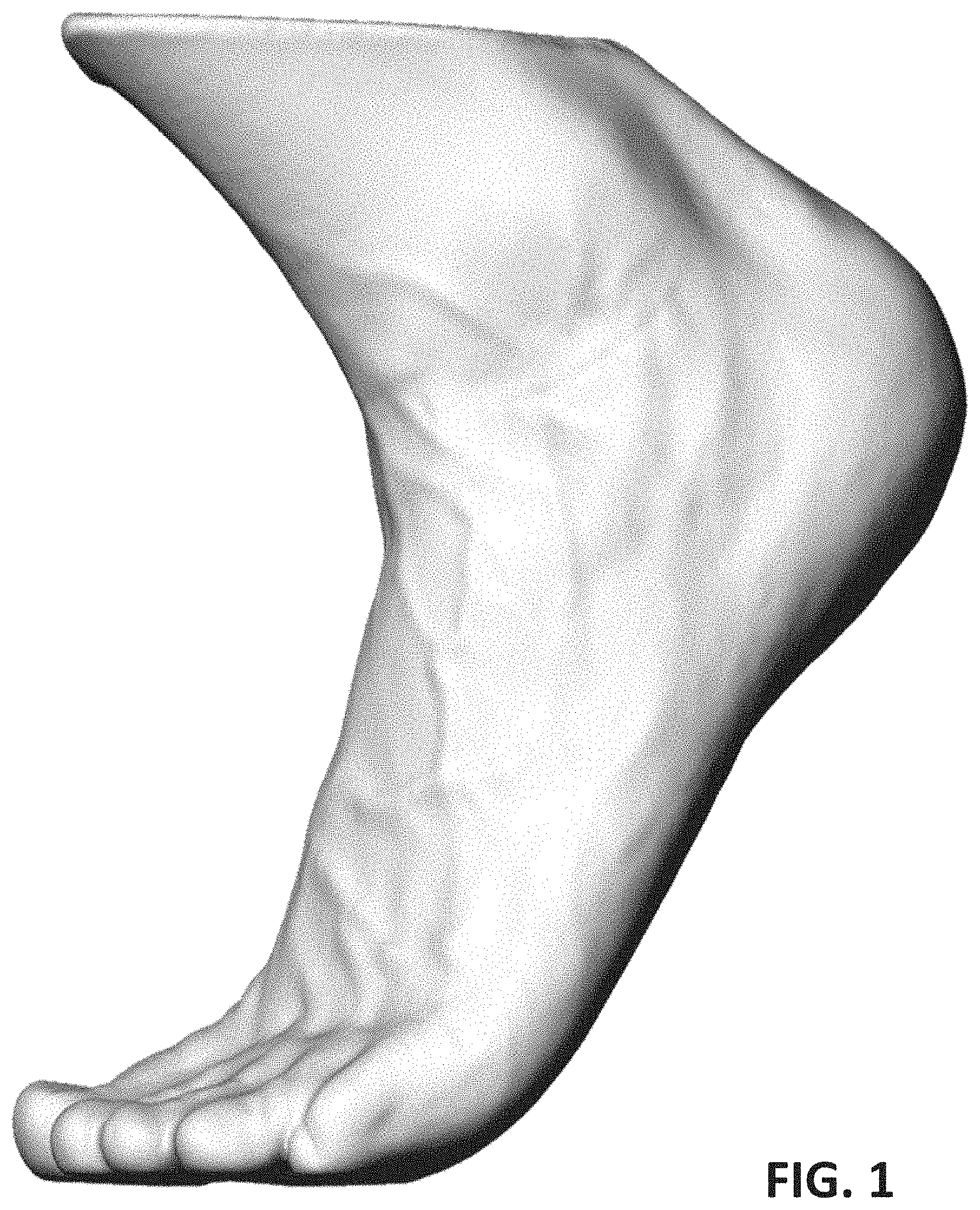
[0008] FIG. 1 shows an example foot in an active stance.
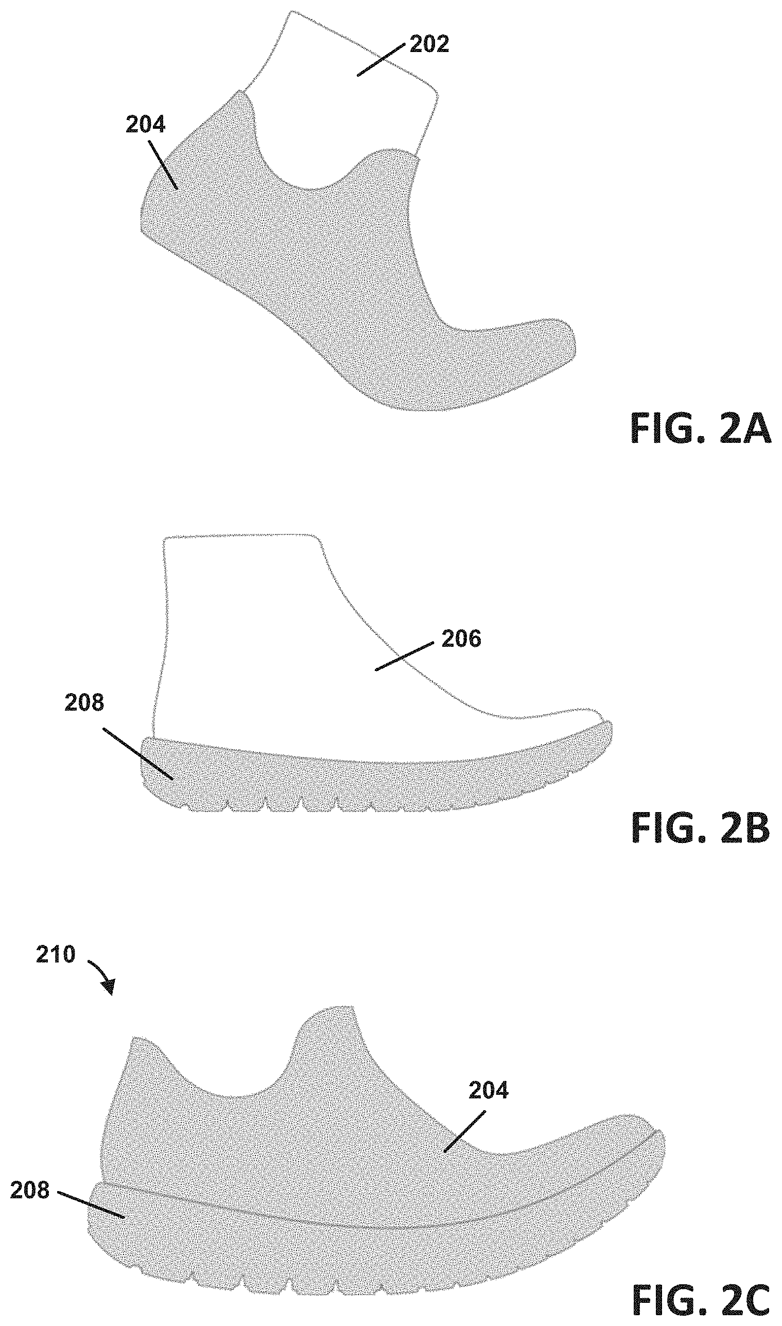
[0009] FIG. 2A shows an example stage of forming footwear using an active last.
[0010] FIG. 2B shows another stage of forming footwear using a static last.
[0011] FIG. 2C shows yet another stage of forming footwear.
[0012] FIG. 3 shows a perspective view of an example active last.
[0013] FIG. 4 shows another perspective view of the example active last.
[0014] FIG. 5 shows a side view of an example upper.
[0015] FIG. 6 is a diagram showing another example upper.
[0016] FIG. 7 is a flowchart showing a method for forming footwear.
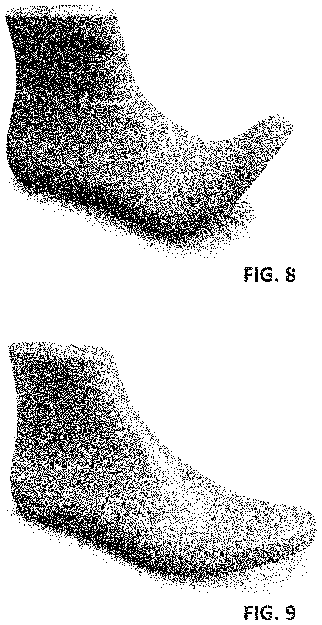
[0017] FIG. 8 shows a perspective view of an example active last.
[0018] FIG. 9 shows a perspective view of an example static last.
DETAILED DESCRIPTION OF ILLUSTRATIVE EMBODIMENTS
[0019] An article of footwear, a method of making the footwear, and an active last for forming the footwear are disclosed herein. The active last of the present disclosure may be used to model an active stance. Modeling the active stance may comprise having a shape representative and/or similar to a shape of the active stance. The shape may represent and/be based one curves, contours, lengths, volumes, and/or the like of a foot. A model may comprise an object and/or form of the same size of a representative foot or a proportional size. The active last as a model does not need to match exactly a particular foot, though such matching may be appropriate in custom footwear. For example, one or more sections of the active last may have a reduced or enlarged size. A width, length, volume, and/or the like of the active last may be increased to allow room for a sock in the resulting footwear made using the active last. Modifications in the size of active last may allow for added support, comfort, and/or to ensure that the resulting footwear fits variations of feet shapes and sizes. For example, an arch in the active last described herein may be increased in size than is typical for a foot to provide greater arch support (e.g., for feet with smaller arches). The active last may be used for forming at least a portion of footwear. As an example, the active last in accordance with the present disclosure may be used for forming an upper of footwear. The upper may be coupled with a sole to form the footwear. The footwear of the present disclosure may have a natural position (e.g., resting position) that accommodates (e.g., fits) a foot of a wearer when in an active stance. The nature position may provide a comfortable fit through use of flexible and/or stretchable materials in the upper and sole. These flexible and/or stretchable materials may allow the footwear to still be comfortable even when the user is in a relaxed stance, instead of an active stance. The fit may relate to various sizes. For example, the footwear may be formed in a variety of sizes, and wearers may select the size that the wearer judges to be most comfortable.
[0020] FIG. 1 shows an example foot in an active stance (e.g., or active position). Conventional shoes may not perform well when a wearer is in an active stance. An active stance may be a stance associated with movement of the foot and/or balancing on a portion of a foot. In the active stance, a person may be engaged in an activity, such as running, exercising, walking, jumping, and/or the like. In the active stance, the foot may be supported (e.g., balanced on, resting on) by a forefoot, the wearer's toes, the ball (e.g., padded portion of the sole between toes and arch) of the wearer's foot, and/or the like. In a supported and/or balanced state, a wearer may be able to stand on only a portion of the foot without falling. In a supported and/or balanced state, a wearer may be able to may be able to run, jump, or perform any action without loss of control. In the active stance, muscles may be contracted, flexed, and/or the like to support and/or balance the wear. In the active stance, the wearer may be ready to perform an activity (e.g., without or with little hesitation). In a relaxed stance, a foot may remain stationary and/or rest substantially flat on a surface.
[0021] The foot has a dynamic shape as the foot changes from a relaxed stance to an active stance. The arch changes shape significantly as the foot flexes. The arch lifts up pulling away from the sole of a shoe creating opportunities for irritation. The foot has a dynamic length as the foot changes from a relaxed stance to the active stance. The top of the foot shortens in length as the foot flexes. This shortening in length can create wrinkles in an upper of a shoe. The wrinkles may distort the upper thereby compromising fit, support, shape, and/or the like. In the active stance, the angle between the foot and the ankle/leg may change (e.g., decrease). This change may be referred to as canting (e.g., tilting, angling) of the leg with respect to the foot. Example properties relating to the foot may comprise the angle of flex in the forefoot of e.g., 30 degrees, and the angle of ankle flex of e.g., 17 degrees.
[0022] FIG. 2A, FIG. 2B, and FIG. 2C show formation of footwear 210 based on an active stance and a static stance. FIG. 2A shows a stage in the formation of the footwear 210. The stage may use an example active last 202 (e.g., form, model, last). The active last 202 may be used to form an upper 204 (e.g., or upper pattern). The upper 204 may be formed above, around, upon, on top of, and/or the like the active last 202. The upper 204 may take the shape of and/or conform to the shape of the active last 202.
[0023] The active last 202 and the upper 204 may be based on an active stance. The active last 202 may model a foot in an active stance. The active last may model a shape (e.g., general shape) of the foot in the active stance. The active last 202 may omit detailed features of the foot, such as veins, bones, and/or individual toes. Similar to the active stance shown in FIG. 1, the active last 202 may have a curvilinear shape. The curvilinear shape may comprise a curve that models a natural curve of a foot when in an active stance. Similar to the active last 202, the upper 204 may have a curvilinear shape. The curvilinear shape may comprise a curve that models a natural curve of a foot when in an active stance.
[0024] The active last 202 may be a customized last that has been engineered to model a foot in the active stance. Three-dimensional scanning or other measurement technique may be employed based on sound waves, light reflection (e.g., LIDAR), radio waves (e.g., RADAR), millimeter waves, magnetic resonance imaging, video capture, image capture, and/or the like. These measurements may be used to construct a software based model. The software based model, and/or associated measurements (e.g., or instructions based on measurements) may be input into a manufacturing device, such as a 3D-printer, computer numerical control (CNC) device, robot, laser cutter, and/or the like. The manufacturing device may form the active last using wood, plastic, metal, ceramic, and/or other materials.
[0025] FIG. 2B shows another stage of forming the footwear 210. This stage may occur before, after, or simultaneous to the stage shown in FIG. 2A. In this stage, a static last 206 may be used. The static last 206 may be used to form a sole 208. The sole 208 may be formed under the static last 206.
[0026] The static last 206 may have features customized as described further herein. For example, the static last 206 may comprise a customized version of a production last. The static last 206 may model a relaxed stance (e.g., or more closely model the relaxed stance than the active last 202). The static last 206 may have an arch that is less curved than the active last 202. The static last 206 may have a curve in the forefoot that is based on a resting position. The static last 206 may have a forefoot that is curved upward less than the curve of the active last 202. Example angles of forefoot flex for the static last may be from 0 to 20 degrees. Example angles of forefoot flex for the active last may be from 30 to 50 degrees, but could be made to accommodate 90 degrees in certain end-use case.
[0027] The sole 208 may be formed according to a shape of (e.g., the bottom of) the static last 206. The sole 208 may have one or more angles, curves, and/or the like that match the shape of the static last 206. The sole 208 may be a flexible sole. However, the level of flexibility or elasticity may be configured for a particular footwear article. The sole 208 (e.g., or sole unit) may be engineered (e.g., determined, formed, designed) using the static last 206 to fit the foot in a relaxed stance (e.g., static position).
[0028] FIG. 2C shows yet another stage of forming footwear 210. In this stage, the footwear 210 is formed by combining the upper 204 and sole 208. The footwear 210 may be formed by attaching (e.g., gluing, fastening, pressing, melting) the upper 204 to the sole 208. The upper 204 may be pressed to the sole 208 using the static last 206.
[0029] The resulting footwear 210 may be spring-loaded. The footwear 210 may be configured to spring back (e.g., revert back, move back, return) from an unnatural position (e.g., when a force is applied to distort the shape) into the natural or resting position of the footwear 210. The footwear 210 may resist movement from the resting or natural position (e.g., active stance). The sole 208 may be flexible enough to adapt to the terrain. The resting position of the footwear 210 may be different than the resting position of the upper 204 before assembly into the footwear 210. The angle of a front portion of the upper 204 may be different than an angle of a front portion of the sole. This difference may result from difference in angles of the active last 202 and static last 206. The difference in angles in the upper 204 and the sole 208 may cause tension between the sole 208 and upper 204. The tension may be due to the exertion of opposing forces between the sole 208 and the upper 204. The resting position of the footwear 210 may be an equilibrium between the opposing forces. The upper 204 may more stretchable than the sole 208. The sole 208 may be more rigid than the upper 204. When the upper 204 and sole 208 are assembled together, the sole 208 may cause the upper 204 to be in a stretched state in the resting position of the footwear 210. The upper 204 may further stretch and unstretch in response to movement of the foot.
[0030] FIG. 3 shows a perspective view of the example active last 300. The active last 300 may comprise solid (or hollow) model that may be shaped like a foot. The model may be shaped to facilitate forming footwear to the active stance of a foot as opposed to a flat stance or inactive position, as is conventional. The active last 300 may comprise a heel portion 302. The heel portion 302 may be disposed at a first end 304 (e.g., of the active last 300). The active last 300 may comprise a forefoot portion 306. The forefoot portion 306 may be disposed adjacent a second end 308 (e.g., of the active last 300). The second end 308 may be opposite the first end 304.
[0031] At least a portion of the forefoot portion 306 may have a curvilinear shape. The curvilinear shape may curve upwardly from a horizontal axis 310. The curvilinear shape may model an active stance. The curvilinear shape may be indicative of and/or comprise a toe spring in which the toes are angled to support the foot. The curvilinear shape may comprise a bend (e.g., a curve, a curved bend) on a topside of the forefoot portion 306. The curvilinear shape may comprise a bend (e.g., a curve, a curved bend) on a bottom side of the forefoot portion 306. The bend may transition into a linear shape. The curvilinear shape may comprise a top side and a bottom side that straighten after the bend. The top side and bottom side may gradually taper as the top side and/or bottom side extend towards a rounded tip at the second end 308.
[0032] The active last 300 may comprise an arch 312 along a bottom side 314 of one or more of the heel portion 302 or the forefoot portion 306. A curve of the arch 312 may be based on the active stance. For example, one or more measurements may be determined for a foot (e.g., or a variety of feet of different sizes). The one or more measurements may comprise three-dimensional scan data. The curve of the arch 312 may be based on the one or more measurements, the three-dimensional scan data, and/or the like. In certain aspects, the bottom area of the last known as the "bottom paper" may match between the active and the static last.
[0033] An angle 316 of the forefoot portion 306 may be based on an angle associated with the active stance. For example, one or more measurements may be determined for a foot (e.g., or feet of a variety of different sizes). An average angle of the active stance may be determined (e.g., generally, or for a specific footwear size). The angle 316 of the forefoot portion 306 from the horizontal axis 310 may be more than 20 degrees, more than 30 degrees, more than 40 degrees, more than 50 degrees, and/or from about 40 degrees to about 60 degrees. The angle 316 of the forefoot portion 306 from the horizontal axis 310 may be from about 45 degrees to about 55 degrees. The angle 316 of the forefoot portion 306 from the horizontal axis 310 may be from about 48 degrees to about 52 degrees. The angle 316 of the forefoot portion 306 from the horizontal axis 310 may be from about 49 degrees to about 51 degrees. The angle 316 of the forefoot portion 306 from the horizontal axis 310 may be about 50 degrees. As an example, footwear may be designed or configured for at least one particular end-use or activity. As a further example, an end-use of road running, trail running, or hiking the forefoot flex angle may be around 30 degrees. However other angles may be used as this is an illustrative example only. As a further example, a 90 degree active last may be configured to allow the foot to flex the full range of motion of 90 degrees where the end user is engaging in activities such as push-ups, planks, yoga, etc. Other activities and configurations of the active last may be used.
[0034] The active last 300 may comprise a shaft 318 extending from a top side 320 of the heel portion 302 for modeling a leg. A length of the shaft 318 may allow for forming an upper to cover an ankle of a wearer. The shaft 318 may be canted (e.g., tilted, angled). The shaft 318 may be canted based on the active stance or dependent on an angle of the active stance. The shaft 318 may be canted forward (e.g., 0 to +25 degrees relative to axis 317) toward the toe or second end 308, or may be canted backward (e.g., 0 to -25 degrees relative to axis 317) away from the toe or second end 308. The shaft 318 may be canted from about 0 degrees to +/-25 degrees toward or away from the toe or second end 308 relative to an axis 317 orthogonal to the horizontal axis 310 toward. The shaft 318 may be canted from about +/-10 degrees to +/-25 degrees toward or away from the toe or second end 308. The shaft 318 may be canted from about +/-15 degrees to about +/-20 degrees toward or away from the toe or second end 308. As a non-limiting example, the shaft 318 may be canted forward or away from the axis 317 by about +/-17 degrees. Canted may comprise dorsiflexion. The dorsiflexion of the active last (as it relates to the foot) +/-10 to 25 degrees, +/-15 to 20 degrees, and/or about +/-17 degrees.
[0035] A size of one or more of the heel portion 302 or the forefoot portion 306 may be adjusted for forming a compression fit of an upper using a stretch material. The size may be adjusted by increasing or decreasing the volume. The volume of the active last 300 may be adjusted to account for the stretch material. For example, the volume may be decreased if a stretch material is used.
[0036] FIG. 4 shows another perspective view of the example active last 300. The active last 300 is shown in an active stance position to illustrate that the active last 300 models the active stance shown in FIG.1.
[0037] FIG. 5 shows a side view of an example upper 500. The upper 500 may be part of an article of footwear as described herein. The upper 500 may comprise an upper portion (e.g., fabric portion) of the footwear that is typically attached to a sole. The upper 500 may comprise a front portion 502 for enclosing a forefoot (e.g., of a wearer, when assembled as footwear).
[0038] The front portion 502 may have a curvilinear shape. The curvilinear shape may curve upwardly from a horizontal axis (e.g., such as horizontal axis 310). For example, the curvilinear shape may comprise a bend in the upper 500. The bend may be between the front portion 502 and a back portion 504 of the upper 500. The curvilinear shape may curve upwardly in a resting position. The resting position may be the natural position of the upper 500 and/or footwear in which the upper 500 is assembled. The resting position may be a position in which no force or minimal force is applied to the upper 500 and/or footwear in which the upper 500 is assembled. The curvilinear shape may be based on active stance of a wearer. The curvilinear shape may curve upwardly to fit an active stance of a wearer. The curvilinear shape may curve more than a curve of an upper patterned based on a relaxed stance (e.g., or static stance).
[0039] The curvilinear shape of the upper 500 may be based on the curvilinear shape of the active last (e.g., as shown in FIG. 3-4). An angle of the front portion 502 from the horizontal axis may be from about 40 degrees to about 60 degrees. The angle of the front portion 502 from the horizontal axis may be from about 45 degrees to about 55 degrees. The angle of the front portion 502 from the horizontal axis may be from about 48 degrees to about 52 degrees. The angle of the front portion 502 from the horizontal axis may be from about 49 degrees to about 51 degrees. The angle of the front portion 502 from horizontal axis may be about 50 degrees.
[0040] The upper 500 may be configured to resist movement from the resting position. The upper 500 may comprise a flexible, resilient, stretchable, breathable, flexible, and/or the like material. The upper 500 may be configured to hold the curvilinear shape when no force or a small amount of force is applied. The upper 500 may be configured to return to, move back to, spring back to, and/or the like the original and/or natural form (e.g., resting position) of the upper 500 (e.g., when assembled in footwear by itself) after a force is applied. The upper 500 may apply a force to resist the shape of a sole attached to the upper 500. As an example, the upper 500 may be configured to be elastic enough to return to the original shape of the active last during flex. The upper 500 may be configured to not exceed the elastic limit of the material when in the static position. In other words, the upper 500 may be elastic enough to allow the foot to overcome the tension of the upper and rest in the static position without too much resistance. The direction of the elasticity may be oriented from heel to toe to allow this. The upper 500 may be engineered to have a bias in stretch. For instance, the upper 500 may stretch more from the heel to toe direction than in the lateral to medial direction.
[0041] The front portion 502 may comprise a plurality of flexible members 506. The plurality of flexible members 506 may comprise a plurality of flexible tubes. The plurality of flexible members 506 may be disposed within a fabric layer of the upper 500 (e.g., or a fabric layer of the front portion 502). The plurality of flexible members 506 may comprise a flexible material. Plurality of flexible members 506 may be hollow. The plurality of flexible members 506 allow the foot to easily overcome the toe-spring (e.g., the curvilinear shape). This configuration maximizes ground contact while still providing continuous support from the compression fit. As an example, the tubes are formed via an engineered knitting process as one integrated component. The tubes may be formed by bonding two layers together, such as understood in pre-stretch hot-melt processes.
[0042] As previously mentioned, the upper 500 may comprise a back portion 504. The front portion 502 may extend from the back portion 504. The back portion 504 may extend from the front portion 502. The back portion 504 may comprise a top side 508. The back portion 504 may comprise a bottom side 510. The top side 508 may be disposed to enclose an ankle of a wearer. The top side 508 may extend above an ankle of a wearer. The top side 508 may be canted (e.g., titled, angled) based on the active stance. The top side 508 may be canted forward. The top side 508 may be canted forward from about 10 degrees to about 25 degrees. The top side 508 may be canted forward from about 15 degrees to about 20 degrees. As a non-limiting example, the top side 508 may be canted forward 17 degrees.
[0043] The upper 500 may comprise one or more fabric layers. The one or more fabric layers may comprise dynamic fibers, flexible fibers, moisture resistant fibers, thermally resistant or conductive fibers, a combination thereof, and/or the like. The one or more fabric layers may comprise polyester fibers, spandex fibers, a combination thereof, and/or the like. The upper 500 may comprise knit, such as flat-knitting, engineered flat knitting, and/or the like. The upper 500 may comprise a base fabric layer, such as a one-piece base fabric layer comprising the front portion 502 and the back portion 504. As another example, the base fabric layer may comprise multiple pieces. For example, the front portion 502 may be one piece, and the back portion 504 may be another piece. The front portion 502 and the back portion 504 may be attached together. The one or more fabric layers, the base layer, and/or the knit may be shaped based on the active last described herein. The one or more fabric layers may be moisture resistant. The one or more fabric layers may be coated with a moisture resistant material. Durable water repellant (DWR) may be integrated into (e.g., or coated on to) the fibers of the one or more fabric layers. For example, whole-shoe coating may be applied to cause the shedding of moisture due to the elements or perspiration. The upper 500 (e.g., the one or more fabric layers) may be formed by laser cutting.
[0044] The upper 500 may comprise a plurality of fabric zones 512. The plurality of fabric zones 512 may be integrated (e.g., knit, interwoven, applied) into the one or more fabric layers. One or more (or each) of the plurality of fabric zones 512 may comprise a corresponding material. The materials may be associated with corresponding characteristics (e.g., performance characteristics), such as strength characteristics, durability characteristics, thermo-regulatory characteristics, comfort characteristics, safety/visibility characteristics and/or the like. For example, one or more specialty yarns may be formed (e.g., knit) in the plurality of fabric zones 512. One zone may be associated with one set of characteristics (e.g., a single or combination of characteristics). Another zone may be associated with another set of characteristics. The materials may comprise nylon (e.g., high tenacity nylon), dyneema, a combination thereof, and/or the like (e.g., for adding strength to one or more of the plurality of zones). The material may comprise TPU sheath, polyester core yarns, a combination thereof, and/or the like (e.g., for adding durability to one or more of the plurality of zones,). The materials may comprise hollow core nylon, wool, nylon, a combination thereof, and/or the like (e.g., for adding thermo-regulation to one or more of the plurality of zones). The materials may comprise spun polyester, and/or the like (e.g., for adding comfort to one or more of the plurality of zones). The materials may comprise a reflective material, a luminescent material, a combination thereof, and/or the like (for adding safety and/or visibility to one or more of the plurality of zones). As an example, low temperature Hotmelt TPU yarns may be used in areas 510 and 502. As a further example, area 508 may be spandex yarns. As yet a further example, areas 506 and 504 may be high stretch polyester yarn or a blend of spandex and polyester yarns. However, other materials may be used.
[0045] The upper 500 may be coupled (e.g., glued, attached, affixed, fastened) to a flexible sole (e.g., as shown in FIG. 2C). The flexible sole may comprise a flexible material, such as rubber. The upper 500 may be coupled to the sole using a static last as described herein.
[0046] FIG. 6 is a diagram showing another example upper 600. The upper 600 may comprise some or all of the features of the example uppers as described elsewhere herein. The upper 600 may comprise additional features. The upper 600 may comprise one or more lace loops 602, such as eye-stay lace loops. The lace loops 602 may be hot-melt bonded to the interior of the upper 600. The lace loops 602 may be fed through the quarter panel to the exterior of the upper 600.
[0047] The upper 600 may comprise an ankle support 604. The ankle support 604 may be integrated into or attached to the one or more fabric layers. The ankle support 604 may provide support (e.g., proprioceptive support) at the ankle joint (e.g., without compromising fit or ease-of-entry).
[0048] The upper 600 may comprise a heel reinforcement 606. The heel reinforcement 606 may be integrated into or attached to the one or more fabric layers. The heel reinforcement 606 comprise a one-piece heel reinforcement. The heel reinforcement 606 may be disposed to reduce heel slip and/or increase comfort in the heel. The heel reinforcement 606 may be hot-melt bonded over the heel seam (e.g., greatly reducing heel slip and eliminating irritation from the seam).
[0049] The upper 600 may comprise a quarter reinforcement 608. The quarter reinforcement 608 may be integrated into or attached to the one or more fabric layers. The quarter reinforcement 608 may be disposed in a quarter area of the upper 600. The quarter reinforcement 608 may be disposed to lock the foot down (e.g., decrease movement of the foot). The quarter reinforcement 608 may be disposed to provide lateral support.
[0050] The front portion (e.g., or forefoot) of the upper 600 may have no or minimal reinforcement to allow the foot to splay (e.g., to take full advantage of the comfort that the knit construction offers).
[0051] FIG. 7 is a flowchart showing a method for forming footwear. At step 702, an upper may be formed. Forming the upper may comprise forming one or more fabric layers. One or more fabric zones of various characteristics may be integrated (e.g., knit) into the one or more fabric layers. The fabric zones may support various functions such as comfort, moisture control, thermal control, durability, strength, and/or the like.
[0052] The upper may be formed using an active last. The active last may be formed. The active last may be formed based on one or parameters, measurements, three models, and/or the like associated with an active stance. The active last may comprise the active last as described herein. The upper may be formed on (e.g., above, around, over, upon) the active last. For example, the upper may be knit on top of the active list.
[0053] The upper may comprise a front portion. The front portion may have a curvilinear shape. The front portion may have a curvilinear shape in a resting position. The curvilinear shape may be based on a curved forefoot of an active last used to form the upper. The curvilinear shape may curve upwardly from a horizontal axis (e.g., horizontal axis 310) to fit an active stance of a wearer. An angle of the front portion from the horizontal axis may be more than 20 degrees, more than 30 degrees, more than 40 degrees, more than 50 degrees, and/or from about 40 degrees to about 60 degrees. The angle of the front portion from the horizontal axis may be from about 45 degrees to about 55 degrees. The angle of the front portion from the horizontal axis may be from about 48 degrees to about 52 degrees. The angle of the front portion from the horizontal axis may be from about 49 degrees to about 51 degrees. The angle of the front portion from horizontal axis may be about 50 degrees.
[0054] The upper may be configured to resist movement from the resting position. The upper may comprise a flexible, resilient, stretchable, breathable, flexible, and/or the like material. The upper may be configured to hold the curvilinear shape when no force or a small amount of force is applied. The upper may be configured to return to, move back to, spring back to, and/or the like the original and/or natural form (e.g., resting position) of the upper (e.g., when assembled in footwear by itself) after a force is applied. The upper may apply a force to resist the shape of a sole attached to the upper.
[0055] The upper may comprise a back portion. The back portion may comprise a top side and a bottom side. The top side may be configured to extend above an ankle of a wearer. The top side may be canted based on the active stance. The top side may be canted forward from about 10 degrees to about 25 degrees. The top side may be canted forward from about 15 degrees to about 20 degrees. As a non-limiting example, the top side may be canted forward 17 degrees.
[0056] At step 704, a flexible sole may be coupled to the upper. A static last may be formed. The static last may comprise the static last as described herein. Coupling the sole to the upper may be based on the static last. The sole may be formed based on the static last. The static last may be used to press the sole to the upper. The static last may be different than the active last. The forefoot of the active last may be curved more than a forefoot of the static last. The forefoot of the active last may have an amount of curvature with respect to the horizontal axis that is greater than an amount of curvature with respect to the horizontal axis than a forefoot of the static last. The active last may comprise a first arch on a bottom side of the active last. The static last may comprise a second arch on a bottom side of the static last. The first arch may be larger than the second arch. The first arch may be longer, deeper, wider, more contoured, and/or the like than the second arch. In some scenarios, the static last may have no arch or a minimal arch in comparison to the active last.
[0057] The present disclosure comprises at least the following aspects:
[0058] Aspect 1: An active last for forming footwear comprising: a heel portion disposed at a first end; and a forefoot portion disposed adjacent a second end, opposite the first end, wherein at least a portion of the forefoot portion has a curvilinear shape that curves upwardly from a horizontal axis to model an active stance, and wherein an angle of the forefoot portion from the horizontal axis is greater than 25 degrees.
[0059] Aspect 2: The active last of claim 1, wherein the footwear is configured for at least one particular activity and an angle of the forefoot portion from the horizontal axis is dependent upon the at least one particular activity.
[0060] Aspect 3: The active last of any of claims 1-2, further comprising an arch along a bottom side of one or more of the heel portion or the forefoot portion, and wherein a curve of the arch is configured based on the active stance.
[0061] Aspect 4: The active last of any of claims 1-3, wherein an angle of the forefoot portion from the horizontal axis is from about 40 degrees to about 60 degrees.
[0062] Aspect 5: The active last of any of claims 1-4, wherein an angle of the forefoot portion from horizontal axis is about 50 degrees.
[0063] Aspect 6: The active last of any of claims 1-5, further comprising a shaft extending from a top side of the heel portion for modeling a leg, wherein a length of the shaft allows for forming an upper to cover an ankle of a wearer.
[0064] Aspect 7: The active last of claim 6, wherein the shaft is canted based on the active stance.
[0065] Aspect 8: The active last of claim 6, wherein the shaft us canted from -20 degrees to +20 degrees from an axis that is perpendicular to the horizontal axis.
[0066] Aspect 9: The active last of any of claims 1-8, wherein a size of one or more of the heel portion or the forefoot portion is adjusted for forming a compression fit of an upper using a stretch material.
[0067] Aspect 10: An article of footwear comprising: an upper comprising a front portion for enclosing a forefoot, wherein the front portion has a curvilinear shape that curves upwardly in a resting position from a horizontal axis to fit an active stance of a wearer, wherein the upper is configured to resist movement from the resting position; and a flexible sole coupled to the upper, wherein an angle of the front portion from the horizontal axis is greater than 25 degrees.
[0068] Aspect 11: The article of claim 10, wherein the footwear is configured for at least one particular activity and the active stance is dependent upon the at least one particular activity.
[0069] Aspect 12: The article of any of claims 10-11, wherein the footwear is configured for at least one particular activity and an angle of the front portion from the horizontal axis is dependent upon the at least one particular activity.
[0070] Aspect 13: The article of any of claims 10-12, wherein the front portion comprise a plurality of flexible tubes disposed in a fabric side of the front portion.
[0071] Aspect 14: The article of any of claims 10-13, wherein an angle of the front portion from the horizontal axis is from about 40 degrees to about 60 degrees.
[0072] Aspect 15: The article of any of claims 10-14, wherein an angle of the front portion from the horizontal axis is about 50 degrees.
[0073] Aspect 16: The article of any of claims 10-16, wherein the upper comprises a back portion having a top side and a bottom side, and wherein the top side is configured to extend above an ankle of a wearer.
[0074] Aspect 17: The article of claim 16, wherein the top side is canted based on the active stance.
[0075] Aspect 18: The article of claim 16, wherein the top side is canted from -20 degrees to +20 degrees from an axis that is perpendicular to the horizontal
[0076] Aspect 19: The article of any of claims 10-18, wherein the upper comprises a plurality of fabric zones, each of the plurality of fabric zones comprising a corresponding material.
[0077] Aspect 20: A method of making footwear comprising: forming an upper comprising a front portion, wherein in a resting position the front portion has a curvilinear shape, based on a curved forefoot of an active last used to form the upper, that curves upwardly from a horizontal axis to fit an active stance of a wearer, wherein the upper is configured to resist movement from the resting position; and coupling a flexible sole to the upper.
[0078] Aspect 21: The method of claim 20, further comprising forming the active last and forming a static last, wherein coupling the sole to the upper is based on the static last, wherein the forefoot of the active last has an amount of curvature with respect to the horizontal axis that is greater than an amount of curvature with respect to the horizontal axis than a forefoot of the static last.
[0079] Aspect 22: The method of claim 21, wherein the active last comprises a first arch on a bottom side of the active last and the static last has a second arch on a bottom side of the static last, and wherein the first arch is larger than the second arch.
[0080] Aspect 23: The method of any of claims 20-22, wherein an angle of the front portion from the horizontal axis is from about 40 degrees to about 60 degrees.
[0081] Aspect 24: The method of any of claims 20-23, wherein an angle of the front portion from the horizontal axis is about 50 degrees.
[0082] Aspect 25: The method of any of claims 20-24, wherein the upper comprises a back portion, wherein the back portion comprises a top side and a bottom side, and wherein the top side is configured to extend above an ankle of a wearer.
[0083] FIG. 8 shows a perspective view of an example active last. The active last may have the features of the example active lasts as described elsewhere herein. FIG. 9 shows a perspective view of an example static last. The static last may have the features of the example static lasts as described elsewhere herein. The static last may be used for pressing the upper to the sole. The static last may differ from a typical production last. The heel/ball offset may be reduced as compared to a typical production last. The heel/ball offset may be reduced to put the foot in a more neutral position. The heel/ball offset may be reduced, for example, to 4 mm. The arch in the arch area may differ from the arch of the active last. The arch added to the active last may not be included in the static last. The volume of the static last may be adjusted to account for stretch materials. The static last may have a sock-liner allowance. The sock-liner allowance may be selected to protect the foot and reduce the sensation of the arch lifting off the sole unit during flex. For example, the sock-liner allowance may be 6mm. The static last may have an increased toe spring (e.g., upward curve of the front portion) as compared to a typical production last. In certain aspects, differences between the active and static lasts allow one to pre-tension the upper for a particular end-use or activity (e.g., hiking, trail running, street running, etc.). In other aspects, the static last may be configured with a negative toe spring to accommodate the full range of plantarflexion so that the foot can have a complete range of motion for an activity such as rock-climbing, dance, or martial arts, for example.
[0084] It is to be understood that the methods and systems are not limited to specific methods, specific components, or to particular implementations. It is also to be understood that the terminology used herein is for the purpose of describing particular embodiments only and is not intended to be limiting.
[0085] As used in the specification and the appended claims, the singular forms "a," "an," and "the" include plural referents unless the context clearly dictates otherwise. Ranges may be expressed herein as from "about" one particular value, and/or to "about" another particular value. When such a range is expressed, another embodiment includes from the one particular value and/or to the other particular value. Similarly, when values are expressed as approximations, by use of the antecedent "about," it will be understood that the particular value forms another embodiment. It will be further understood that the endpoints of each of the ranges are significant both in relation to the other endpoint, and independently of the other endpoint.
[0086] "Optional" or "optionally" means that the subsequently described event or circumstance may or may not occur, and that the description includes instances where said event or circumstance occurs and instances where it does not.
[0087] Throughout the description and claims of this specification, the word "comprise" and variations of the word, such as "comprising" and "comprises," means "including but not limited to," and is not intended to exclude, for example, other components, integers or steps. "Exemplary" means "an example of and is not intended to convey an indication of a preferred or ideal embodiment. "Such as" is not used in a restrictive sense, but for explanatory purposes.
[0088] Ranges can be expressed herein as from one value (first value) to another value (second value). When such a range is expressed, the range includes in some aspects one or both of the first value and the second value. Similarly, when values are expressed as approximations, by use of the antecedent `about,` it will be understood that the particular value forms another aspect. It will be further understood that the endpoints of each of the ranges are significant both in relation to the other endpoint, and independently of the other endpoint. It is also understood that there are a number of values disclosed herein, and that each value is also herein disclosed as "about" that particular value in addition to the value itself. For example, if the value "10" is disclosed, then "about 10" is also disclosed. It is also understood that each unit between two particular units are also disclosed. For example, if 10 and 15 are disclosed, then 11, 12, 13, and 14 are also disclosed.
[0089] As used herein, the terms "about" and "at or about" mean that the amount or value in question can be the designated value, approximately the designated value, or about the same as the designated value. It is generally understood, as used herein, that it is the nominal value indicated .+-.10% variation unless otherwise indicated or inferred. The term is intended to convey that similar values promote equivalent results or effects recited in the claims. That is, it is understood that amounts, sizes, formulations, parameters, and other quantities and characteristics are not and need not be exact, but can be approximate and/or larger or smaller, as desired, reflecting tolerances, conversion factors, rounding off, measurement error and the like, and other factors known to those of skill in the art. In general, an amount, size, formulation, parameter or other quantity or characteristic is "about" or "approximate" whether or not expressly stated to be such. It is understood that where "about" is used before a quantitative value, the parameter also includes the specific quantitative value itself, unless specifically stated otherwise.
[0090] Components are described that may be used to perform the described methods and systems. When combinations, subsets, interactions, groups, etc., of these components are described, it is understood that while specific references to each of the various individual and collective combinations and permutations of these may not be explicitly described, each is specifically contemplated and described herein, for all methods and systems. This applies to all aspects of this application including, but not limited to, operations in described methods. Thus, if there are a variety of additional operations that may be performed it is understood that each of these additional operations may be performed with any specific embodiment or combination of embodiments of the described methods.
[0091] The present methods and systems may be understood more readily by reference to the following detailed description of preferred embodiments and the examples included therein and to the Figures and their descriptions.
[0092] As will be appreciated by one skilled in the art, the methods and systems may take the form of an entirely hardware embodiment, an entirely software embodiment, or an embodiment combining software and hardware aspects. Furthermore, the methods and systems may take the form of a computer program product on a computer-readable storage medium having computer-readable program instructions (e.g., computer software) embodied in the storage medium. More particularly, the present methods and systems may take the form of web-implemented computer software. Any suitable computer-readable storage medium may be utilized including hard disks, CD-ROMs, optical storage devices, or magnetic storage devices.
[0093] Embodiments of the methods and systems are described below with reference to block diagrams and flowchart illustrations of methods, systems, apparatuses and computer program products. It will be understood that each block of the block diagrams and flowchart illustrations, and combinations of blocks in the block diagrams and flowchart illustrations, respectively, may be implemented by computer program instructions. These computer program instructions may be loaded on a general-purpose computer, special-purpose computer, or other programmable data processing apparatus to produce a machine, such that the instructions which execute on the computer or other programmable data processing apparatus create a means for implementing the functions specified in the flowchart block or blocks.
[0094] These computer program instructions may also be stored in a computer-readable memory that may direct a computer or other programmable data processing apparatus to function in a particular manner, such that the instructions stored in the computer-readable memory produce an article of manufacture including computer-readable instructions for implementing the function specified in the flowchart block or blocks. The computer program instructions may also be loaded onto a computer or other programmable data processing apparatus to cause a series of operational steps to be performed on the computer or other programmable apparatus to produce a computer-implemented process such that the instructions that execute on the computer or other programmable apparatus provide steps for implementing the functions specified in the flowchart block or blocks.
[0095] The various features and processes described above may be used independently of one another, or may be combined in various ways. All possible combinations and sub-combinations are intended to fall within the scope of this disclosure. In addition, certain methods or process blocks may be omitted in some implementations. The methods and processes described herein are also not limited to any particular sequence, and the blocks or states relating thereto may be performed in other sequences that are appropriate. For example, described blocks or states may be performed in an order other than that specifically described, or multiple blocks or states may be combined in a single block or state. The example blocks or states may be performed in serial, in parallel, or in some other manner. Blocks or states may be added to or removed from the described example embodiments. The example systems and components described herein may be configured differently than described. For example, elements may be added to, removed from, or rearranged compared to the described example embodiments.
[0096] While the methods and systems have been described in connection with preferred embodiments and specific examples, it is not intended that the scope be limited to the particular embodiments set forth, as the embodiments herein are intended in all respects to be illustrative rather than restrictive.
[0097] Unless otherwise expressly stated, it is in no way intended that any method set forth herein be construed as requiring that its operations be performed in a specific order. Accordingly, where a method claim does not actually recite an order to be followed by its operations or it is not otherwise specifically stated in the claims or descriptions that the operations are to be limited to a specific order, it is no way intended that an order be inferred, in any respect. This holds for any possible non-express basis for interpretation, including: matters of logic with respect to arrangement of steps or operational flow; plain meaning derived from grammatical organization or punctuation; and the number or type of embodiments described in the specification.
[0098] It will be apparent to those skilled in the art that various modifications and variations may be made without departing from the scope or spirit of the present disclosure. Other embodiments will be apparent to those skilled in the art from consideration of the specification and practices described herein. It is intended that the specification and example figures be considered as exemplary only, with a true scope and spirit being indicated by the following claims.
* * * * *
D00000
D00001
D00002
D00003
D00004
D00005
D00006
D00007
D00008
XML
uspto.report is an independent third-party trademark research tool that is not affiliated, endorsed, or sponsored by the United States Patent and Trademark Office (USPTO) or any other governmental organization. The information provided by uspto.report is based on publicly available data at the time of writing and is intended for informational purposes only.
While we strive to provide accurate and up-to-date information, we do not guarantee the accuracy, completeness, reliability, or suitability of the information displayed on this site. The use of this site is at your own risk. Any reliance you place on such information is therefore strictly at your own risk.
All official trademark data, including owner information, should be verified by visiting the official USPTO website at www.uspto.gov. This site is not intended to replace professional legal advice and should not be used as a substitute for consulting with a legal professional who is knowledgeable about trademark law.