Panoramic View System for a Vehicle
ARBEITER; Georg ; et al.
U.S. patent application number 16/469330 was filed with the patent office on 2020-04-09 for panoramic view system for a vehicle. The applicant listed for this patent is Conti Temic microelectronic GmbH. Invention is credited to Georg ARBEITER, Sudhan DHANA SEKARAN, Rodrigo GARCIA MARQUES, Stefan MILZ, Johannes PETZOLD, Joerg SCHREPFER.
| Application Number | 20200112675 16/469330 |
| Document ID | / |
| Family ID | 60515069 |
| Filed Date | 2020-04-09 |
| United States Patent Application | 20200112675 |
| Kind Code | A1 |
| ARBEITER; Georg ; et al. | April 9, 2020 |
Panoramic View System for a Vehicle
Abstract
A panoramic view system for a vehicle includes at least one real camera (2) for capturing an image of the surroundings of the vehicle from non-centered position, a virtual camera (7), an image processing unit, and a display unit which is configured to represent, in a projected manner, the image captured by the real camera (2) and at least one geometric form (11 to 13) as an overlay over the captured image. The image processing unit is configured to project the captured image onto a first plane (9) perpendicular to the real camera (2) such that perspective distortions in the captured image resulting from the non-centered position of the real camera (2) are distortion-corrected, and to project the at least one geometric form (11 to 13) onto a second plane (10) perpendicular to the virtual camera (7) such that the at least one geometric form (11 to 13) is represented in an undistorted manner on the display unit (4). The image processing unit is configured to find an affine transformation (T) between the first plane (9) and the second plane (10) by a delta transformation between the real camera (2) and the virtual camera (7), and to apply the affine transformation (T) to the first plane (9) which contains the projected and distortion-corrected captured image (8') such that a modified representation (8'') of the distortion-corrected captured image (8') is aligned with the at least one undistorted geometric form (11 to 13) in the second plane (10).
| Inventors: | ARBEITER; Georg; (Kueps, DE) ; MILZ; Stefan; (Sallburg-Ebersdorf, DE) ; PETZOLD; Johannes; (Kulmbach, DE) ; SCHREPFER; Joerg; (Tettau, DE) ; DHANA SEKARAN; Sudhan; (Bamberg, DE) ; GARCIA MARQUES; Rodrigo; (Bamberg, DE) | ||||||||||
| Applicant: |
|
||||||||||
|---|---|---|---|---|---|---|---|---|---|---|---|
| Family ID: | 60515069 | ||||||||||
| Appl. No.: | 16/469330 | ||||||||||
| Filed: | October 25, 2017 | ||||||||||
| PCT Filed: | October 25, 2017 | ||||||||||
| PCT NO: | PCT/DE2017/200113 | ||||||||||
| 371 Date: | June 13, 2019 |
| Current U.S. Class: | 1/1 |
| Current CPC Class: | G06T 15/205 20130101; G06T 3/4038 20130101; G06T 2207/30252 20130101; H04N 5/23238 20130101; B60R 2300/102 20130101; G06T 5/006 20130101 |
| International Class: | H04N 5/232 20060101 H04N005/232; G06T 3/40 20060101 G06T003/40 |
Foreign Application Data
| Date | Code | Application Number |
|---|---|---|
| Dec 15, 2016 | DE | 10 2016 225 066.3 |
Claims
1. A panoramic view system for a vehicle, the panoramic view system comprising at least one real camera configured to capture an image of surroundings of the vehicle from a non-centered position, a virtual camera, an image processing unit, and a display unit, wherein the display unit is configured to represent, in a projected manner, the image captured by the real camera, and at least one geometric form as an overlay over the image captured by the real camera, and wherein the image processing unit is configured: to project the image captured by the real camera onto a first plane that is perpendicular to the real camera so that perspective distortions in the image captured by the real camera resulting from the non-centered position of the real camera are distortion-corrected, to project the at least one geometric form onto a second plane that is perpendicular to the virtual camera so that the at least one geometric form is represented in an undistorted manner on the display unit, to find an affine transformation between the first plane and the second plane by a delta transformation between the real camera and the virtual camera, and to apply the affine transformation to the first plane that contains the projected and distortion-corrected image captured by the real camera so that a modified representation of the distortion-corrected image captured by the real camera is aligned with the at least one undistorted geometric form in the second plane.
2. A vehicle comprising a vehicle body and the panoramic view system according to claim 1, wherein the real camera is mounted non-centrally on the vehicle body.
3. A method of representing a panoramic view of surroundings of a vehicle, the method comprising the steps: capturing an image of the surroundings of the vehicle with a real camera from a non-centered position, projecting the image captured by the real camera onto a first plane that is perpendicular to the real camera so that perspective distortions in the image captured by the real camera resulting from the non-centered position of the real camera are distortion-corrected in a projected representation of the image on a display unit, projecting at least one geometric form as an overlay onto a second plane that is perpendicular to the virtual camera so that the at least one geometric form is represented in an undistorted manner on the display unit, finding an affine transformation between the first plane and the second plane by a delta transformation between the real camera and the virtual camera, and applying the affine transformation to the first plane that contains the projected and distortion-corrected image captured by the real camera so that a modified representation of the distortion-corrected image captured by the real camera is aligned with the at least one undistorted geometric form in the second plane.
4. A program element which, when executed on a processor, instructs the processor to perform the method according to claim 3.
5. A computer-readable medium, on which is stored the program element according to claim 4.
Description
[0001] The invention relates to a panoramic view system for a vehicle. The invention further relates to a method for representing a panoramic view of the surroundings of the vehicle. Further claims concern a program element and a computer-readable medium for carrying out the method.
[0002] Representations on display units of a panoramic view system typically include a projected image of a real camera which is mounted on a vehicle and takes pictures of the surroundings of the vehicle. Furthermore, geometric forms are laid as an overlay over the projected image of the camera, wherein the geometric forms can be e.g. a trajectory of the vehicle. In this case, the projected image of the camera must fit the overlay. If, however, the camera is mounted non-centrically on the vehicle, either the overlay or the image of the camera appears distorted. Such a distorted appearance is not desired.
[0003] It is therefore the object of the present invention to provide a panoramic view system and a method of the type indicated above, which make it possible for both the overlay and the image of the camera to be represented in an undistorted manner and aligned with one another in the envisaged manner on a display unit of the vehicle.
[0004] The object is achieved by the subject-matter of the independent claims. Advantageous embodiments are the subject-matter of the dependent claims, the following description as well as the figures.
[0005] According to a first aspect of the invention, a panoramic view system for a vehicle is provided.
[0006] The panoramic view system comprises at least one physical or real camera for capturing an image of the surroundings of the vehicle from a non-centered position. The real camera is preferably a digital camera which can capture images or record film of the surroundings of the vehicle and can store, output and transfer data representing the images acquired or respectively the film. The panoramic view system can also comprise multiple, e.g. four, real cameras which can be mounted on the vehicle in such a manner that individual images of the multiple real cameras can be combined into an entire all-round image (e.g. a 360.degree. all-round image of the vehicle). The at least one real camera is in particular set up to capture a plurality of images of the surroundings of the vehicle from a non-centered position. Even if the present invention is explained in connection with the acquisition of a single image of a single camera, the explanations also apply nevertheless to the other images from the non-centered position of the surroundings of the vehicle of the plurality of images which can be captured by means of at least one real camera. The feature "non-centered position" can, in this connection, in particular mean that the camera is mounted eccentrically and obliquely on or in the vehicle with respect to an imaginary longitudinal axis of the vehicle, and can detect a region ahead of the vehicle.
[0007] Furthermore, the panoramic view system comprises a virtual camera, an image processing unit and a display unit. The image processing unit is, on the one hand, communicatively connected to the real camera. On the other hand, the image processing unit is also communicatively connected to the display unit. In this way, the real camera can in particular transmit image data to the image processing unit, the image processing unit can process the image data and transfer the processed image data to the display unit. The image processing unit can be implemented in a software-based manner.
[0008] The display unit is, on the one hand, set up to represent the image captured by the real camera in a projected manner. On the other hand, the display unit is likewise set up to represent, in a projected manner, at least one geometric form as an overlay over the image captured by the real camera.
[0009] The image processing unit is set up to project the image captured by the real camera onto a first surface or plane which is perpendicular to the real camera such that perspective distortions in the image captured by the real camera resulting from the non-centered position of the real camera are distortion-corrected.
[0010] Furthermore, the image processing unit is set up to project the at least one geometric form onto a second surface or plane which is perpendicular to the virtual camera such that the at least one geometric form is represented in an undistorted manner on the display unit. Consequently, the real camera structurally and physically exists, whereas the virtual camera is merely imaginary or finds its way into the image represented on the display unit and represents a virtual perspective of a user of the panoramic view system according to the invention or of a vehicle having the panoramic view system according to the invention. The second plane is that plane which is represented on the display unit, e.g. on a monitor in the region of the instrument panel of the vehicle, and is visible to a user of the vehicle.
[0011] The image processing unit is further set up to find an affine transformation between the first plane and the second plane by means of a delta transformation between the real camera and the virtual camera, and to apply the found affine transformation to the first plane which contains the projected and distortion-corrected image of the real camera captured by the real camera, such that a modified representation of the distortion-corrected image (which is contained in the first Plane) of the real camera is aligned with the at least one undistorted geometric form in the second plane.
[0012] The delta transformation considers the deviations of the real camera from the virtual camera with respect to the extrinsic camera parameters and the intrinsic camera parameters. To ensure that objects within the image, which is captured by the real camera, are not represented obliquely in the second plane, which would be correct in terms of perspective, it is in particular considered in the case of the delta transformation that the real camera is mounted non-centrically on the vehicle.
[0013] The image of the camera, which has been projected in a distortion-corrected manner onto the first plane, is artificially distorted in this way by means of the affine transformation as if it had been captured from a position of the virtual camera. This makes it possible to represent objects, which are contained in the image captured by the real camera, in the second plane in a distortion-corrected manner and, at the same time, to make possible an undistorted representation of at least one geometric form, e.g. a trajectory of the vehicle, as an overlay in the second plane, wherein the objects and the at least one geometric form are correctly aligned with one another in the second plane.
[0014] According to a second aspect of the invention, a vehicle is provided, which comprises a panoramic view system according to the first aspect of the invention, wherein the real camera is mounted non-centrally on the vehicle. The vehicle is, for example, a motor vehicle such as a car, bus or truck, or also a rail vehicle, a ship, an aircraft such as a helicopter or airplane, or for example, a bicycle.
[0015] According to a third aspect of the invention, a method for representing a panoramic view of the surroundings of a vehicle according to the second aspect of the invention is provided. The method comprises capturing an image of the surroundings of the vehicle by means of the real camera and projecting the image captured by the real camera onto the first plane which is perpendicular to the real camera such that perspective distortions in the image captured by the real camera resulting from the non-centered position of the real camera are distortion-corrected. Furthermore, the at least one geometric form is projected as an overlay onto the second plane which is perpendicular to the virtual camera such that the at least one geometric form is represented in an undistorted manner on the display unit. An affine transformation is further found between the first plane and the second plane by means of a delta transformation between the real camera and the virtual camera, and the found affine transformation is applied to the first plane which contains the projected and distortion-corrected image from the real camera captured by the real camera such that a modified representation of the distortion-corrected image (which is contained in the first plane) of the real camera is aligned with the at least one undistorted geometric form in the second plane.
[0016] According to a fourth aspect of the invention, a program element is provided, which, if it is run on a processor, instructs the processor to perform the method steps according to the method according to the third aspect of the invention.
[0017] According to a fifth aspect of the invention, a computer-readable medium is provided, on which a program element according to the fourth aspect of the invention is stored, which, if it is run on a processor, instructs the processor to perform the method steps according to the method according to the third aspect of the invention.
[0018] Embodiment examples of the invention are explained in greater detail below with reference to the schematic drawing, wherein:
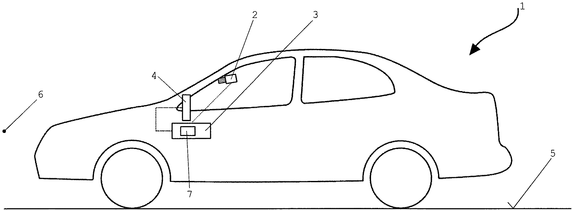
[0019] FIG. 1 shows a side view of a vehicle having one embodiment example of a panoramic view system according to the invention,
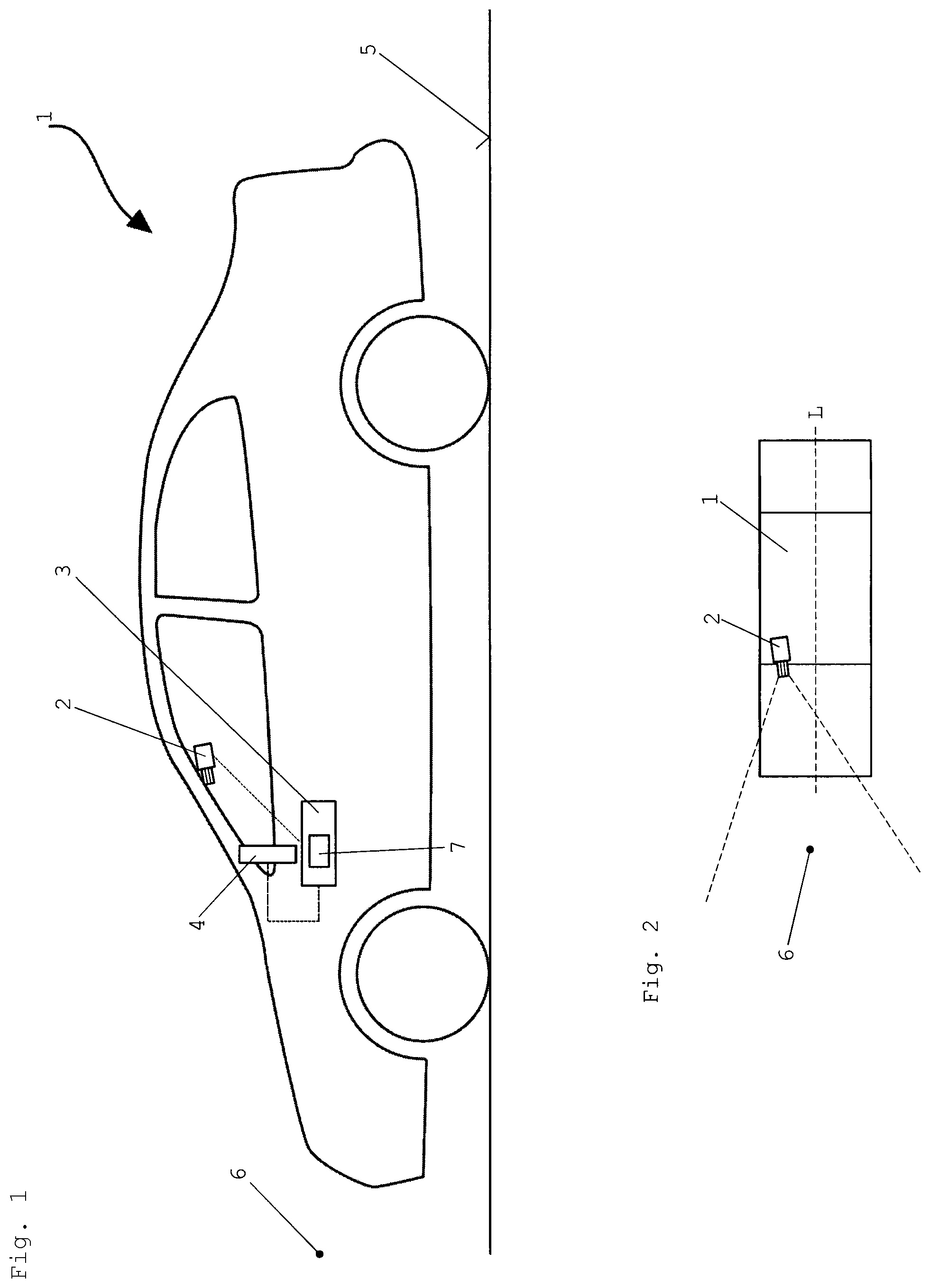
[0020] FIG. 2 shows a considerably simplified top view of the vehicle in accordance with FIG. 1, and
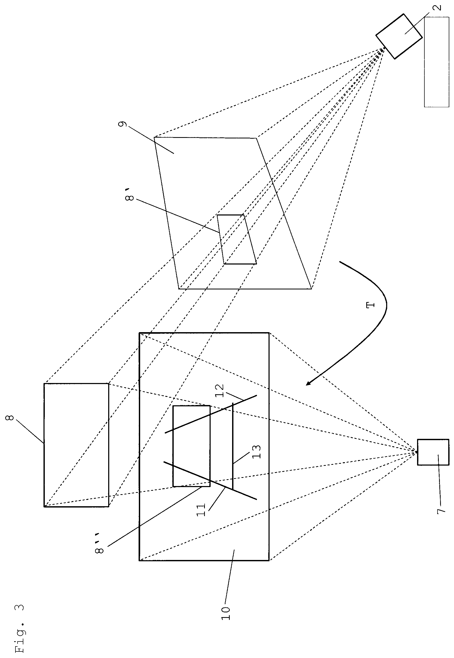
[0021] FIG. 3 shows a fundamental representation of a possible mode of Operation of the panoramic view system in accordance with FIG. 1.
[0022] FIGS. 1 and 2 show a vehicle 1 in the form of a motor vehicle. The vehicle 1 comprises at least one digital physical or real camera 2, an image processing unit 3 and a display unit 4 in the form of a monitor within the vehicle 1 in a field of vision of a user who is not shown. The image processing unit 3 is communicatively connected to the real camera 2 and to the display unit 4 such that the real camera 2 can transmit image data representing captured images to the image processing unit 3 which can, in turn, process the received image data and can transfer the processed image data to the display unit 4. Alternatively, the image processing unit 3 can also be integrated into the real camera 2 or the display unit 4.
[0023] The vehicle 1 is moving on a road 5 and the real camera 2 is mounted on the vehicle 1 in such a way that the real camera 2 can capture images of a region ahead 6 in the external surroundings of the vehicle 1. As can be seen from FIG. 2, the real camera 2 is mounted non-centrally on the vehicle 1. In FIG. 2, a longitudinal axis L of the vehicle 1 is represented, wherein the real camera 2 is mounted laterally offset next to the longitudinal axis L of the vehicle 1 on the vehicle 1. Furthermore, FIG. 2 shows that the real camera 2 can be mounted on the vehicle obliquely, i.e. not parallel to the longitudinal axis L of the vehicle 1. The real camera 2, the image processing unit 3 and the display unit 4 together form the panoramic view system of the vehicle 1, wherein the image processing unit 3 additionally produces a virtual camera 7 which does not exist.
[0024] FIG. 3 shows how an image of the surroundings 6 of the vehicle 1 captured by the real camera 2 can be processed, in order to be represented on the display unit 4 of the vehicle 1 in an all-round image of the vehicle 1. The image captured by the real camera 2 contains multiple objects, wherein one of these objects 8 is represented considerably schematically in FIG. 3. The object 8 can be, for example, a bumper of a further vehicle (not represented) in the region ahead of the vehicle 1. Although the mode of operation of the panoramic view system is explained below with reference to the object 8, these explanations equally apply to the remaining objects (not shown) which are contained in the image captured by the real camera 2.
[0025] The image captured by the real camera 2 having the object 8 is projected onto a first surface or plane 9 which is perpendicular to the real camera 2 such that perspective distortions in the image captured by the real camera 2 resulting from the non-centered position of the real camera 2 are distortion-corrected. In this way, a first modified representation 8' of the object 8 is created within the first plane 9. The image contents of the first plane 9 are not represented on the display unit 4 of the vehicle 1, but rather the image contents of a second plane 10 which is explained below.
[0026] The image processing unit 3 projects at least one geometric form 11 to 13 as an overlay onto the second plane 10 which is perpendicular to the virtual camera 7 such that the second plane 10 having the at least one geometric form 11 to 13 is represented in an undistorted manner on the display unit 4 of the vehicle 1. Three geometric forms which describe a planned trajectory of the vehicle 1 are shown by way of example in FIG. 3.
[0027] Furthermore, the image processing unit 3 finds an affine transformation T between the first plane 9 and the second plane 10 by means of a delta transformation between the real camera 2 and the virtual camera 7, and applies the found affine transformation T to the first plane 9 which contains the first modified representation 8' of the object 8. In this way, a second modified representation 8'' of the object 8 is created within the second plane 10, wherein this second modified representation 8'' is aligned with the at least one undistorted geometric form 11 to 13 in the second plane 10. The second plane having the modified representation 8'' of the object 8 and the geometric forms 11 to 13 is represented on the display unit 4.
* * * * *
D00000
D00001
D00002
XML
uspto.report is an independent third-party trademark research tool that is not affiliated, endorsed, or sponsored by the United States Patent and Trademark Office (USPTO) or any other governmental organization. The information provided by uspto.report is based on publicly available data at the time of writing and is intended for informational purposes only.
While we strive to provide accurate and up-to-date information, we do not guarantee the accuracy, completeness, reliability, or suitability of the information displayed on this site. The use of this site is at your own risk. Any reliance you place on such information is therefore strictly at your own risk.
All official trademark data, including owner information, should be verified by visiting the official USPTO website at www.uspto.gov. This site is not intended to replace professional legal advice and should not be used as a substitute for consulting with a legal professional who is knowledgeable about trademark law.