Immersed Heat Dissipation Device For Power Battery
He; Jisheng ; et al.
U.S. patent application number 16/618180 was filed with the patent office on 2020-04-09 for immersed heat dissipation device for power battery. The applicant listed for this patent is SUGON DATAENERGY(BEIJING) CO., LTD. Invention is credited to Xintao Cui, Lei Han, Jisheng He, Bingshuang Li, Jiawei Liu, Chen Wang, Hongjie Wu, Yingjun Wu, Peng Zhang, Shuai Zhang, Zhihong Zhao.
| Application Number | 20200112073 16/618180 |
| Document ID | / |
| Family ID | 67064273 |
| Filed Date | 2020-04-09 |


| United States Patent Application | 20200112073 |
| Kind Code | A1 |
| He; Jisheng ; et al. | April 9, 2020 |
IMMERSED HEAT DISSIPATION DEVICE FOR POWER BATTERY
Abstract
The present invention relates to an immersed heat dissipation device for power battery, comprising a battery heat dissipation module, a battery unit, a liquid refrigerant, a main inlet pipe and a main outlet pipe, wherein the battery heat dissipation module is a structure of sealed box that contains the liquid refrigerant, and a plurality of the battery heat dissipation modules are connected to each other and arranged in the heat dissipation device for power battery. The battery can be effectively cooled and the temperature of the battery can be effectively controlled, and ensure a uniform temperature for the battery unit, thereby improving the performance and life of the power battery of new energy vehicle.
| Inventors: | He; Jisheng; (Beijing, CN) ; Cui; Xintao; (Beijing, CN) ; Zhang; Peng; (Beijing, CN) ; Li; Bingshuang; (Beijing, CN) ; Wang; Chen; (Beijing, CN) ; Wu; Hongjie; (Beijing, CN) ; Han; Lei; (Beijing, CN) ; Wu; Yingjun; (Beijing, CN) ; Liu; Jiawei; (Beijing, CN) ; Zhang; Shuai; (Beijing, CN) ; Zhao; Zhihong; (Beijing, CN) | ||||||||||
| Applicant: |
|
||||||||||
|---|---|---|---|---|---|---|---|---|---|---|---|
| Family ID: | 67064273 | ||||||||||
| Appl. No.: | 16/618180 | ||||||||||
| Filed: | December 26, 2017 | ||||||||||
| PCT Filed: | December 26, 2017 | ||||||||||
| PCT NO: | PCT/CN2017/118556 | ||||||||||
| 371 Date: | November 29, 2019 |
| Current U.S. Class: | 1/1 |
| Current CPC Class: | H01M 2220/20 20130101; H01M 10/6567 20150401; H01M 10/617 20150401; H01M 10/613 20150401; H01M 10/625 20150401 |
| International Class: | H01M 10/6567 20060101 H01M010/6567; H01M 10/613 20060101 H01M010/613; H01M 10/625 20060101 H01M010/625; H01M 10/617 20060101 H01M010/617 |
Claims
1. An immersed heat dissipation device for power battery, characterized in that, comprising a battery heat dissipation module, a battery unit, a liquid refrigerant, a main inlet pipe and a main outlet pipe, wherein the battery heat dissipation module is a structure of sealed box that contains the liquid refrigerant, and a plurality of the battery heat dissipation modules are connected to each other and arranged in the heat dissipation device for power battery; each of the battery heat dissipation modules is mounted therein with the battery unit, each of the battery units is immersed in the liquid refrigerant in the battery heat dissipation module, and the liquid refrigerant is branched by the main inlet pipe through the liquid inlet to enter the battery heat dissipation module; the liquid refrigerant exchanges heat with the battery unit at the battery heat dissipation module; the liquid refrigerant after the heat exchange flows into the main outlet pipe through a liquid outlet, and flows out of the heat dissipation device for power battery.
2. The immersed heat dissipation device for power battery according to claim 1, characterized in that, the plurality of the battery heat dissipation modules are arranged in a parallel connection manner in the heat dissipation device for power battery.
3. The immersed heat dissipation device for power battery according to claim 1, characterized in that, each of the battery heat dissipation modules further comprises an expansion relief valve.
4. The immersed heat dissipation device for power battery according to claim 1, characterized in that, each of the battery heat dissipation modules further comprises a temperature detection sensor.
5. The immersed heat dissipation device for power battery according to claim 1, characterized in that, the heat dissipation device for power battery further comprises a main communication cable and a main power cable, each of the battery heat dissipation modules has a communication interface connecting the main communication cable, and each of the battery heat dissipation modules has a power interface connecting the main power cable.
6. The immersed heat dissipation device for power battery according to claim 1, characterized in that, the liquid refrigerant is electron fluorinating liquid.
7. The immersed heat dissipation device for power battery according to claim 2, characterized in that, each of the battery heat dissipation modules further comprises an expansion relief valve.
8. The immersed heat dissipation device for power battery according to claim 2, characterized in that, each of the battery heat dissipation modules further comprises a temperature detection sensor.
9. The immersed heat dissipation device for power battery according to claim 2, characterized in that, the heat dissipation device for power battery further comprises a main communication cable and a main power cable, each of the battery heat dissipation modules has a communication interface connecting the main communication cable, and each of the battery heat dissipation modules has a power interface connecting the main power cable.
10. The immersed heat dissipation device for power battery according to claim 2, characterized in that, the liquid refrigerant is electron fluorinating liquid.
Description
FIELD OF THE APPLICATION
[0001] The present invention relates to the technical field of new energy vehicles, in particular, to an immersed heat dissipation device for power battery.
BACKGROUND OF THE APPLICATION
[0002] With the increasing environmental problems, power vehicles are developing rapidly. The power battery is a power source in the electric vehicle and is the core component of the entire power vehicle. The power battery generates a large amount of heat during charging and discharging, resulting in an increase in the temperature of the battery pack. The larger the charge and discharge rate of the power battery, the faster the battery temperature rises, and the power battery pack is usually composed of a plurality of battery cells, which causes a large amount of heat accumulation in the battery pack, and the temperature is too high, affecting the performance and life of the power battery, and may cause safety problems such as thermal runaway or even explosion, therefore, research on the heat dissipation of power battery is of great significance. At present, the commonly used thermal management technologies are air-cooling heat management technology and liquid cooling heat management technology. The air-cooling heat management technology means that the cold air flows through the surface of the battery for heat exchange and cooling. The air-cooling mode is divided into natural cooling and forced cooling (using a fan, etc.). This technology uses natural wind or a fan to cool the battery with the evaporator owned by the vehicle itself together. The liquid-cooling thermal management technology uses a water-cooling method for heat exchange of the battery pack. When the battery is subject to the heat exchange, the battery exchanges heat with the coolant in the pipeline.
[0003] The existing air-cooling thermal management technology has high requirements on the ambient temperature, and the temperature of the inlet air is difficult to control, which makes the temperature of the battery difficult to control, also, for the temperature of the gas, since the heat transfer coefficient of the air is small, the efficiency of heat dissipation is low, and the unevenness of the air flow may cause uneven distribution in the battery pack and affect the uniformity for the temperature of the power battery. For the existing liquid-cooling thermal management technology, typically a liquid-cooling pipe with various structures is interposed between batteries, or a liquid-cooling plate is added between the surface of the battery and the battery, so that the heat generated during charging and discharging of the battery cannot be directly transferred to the cooling liquid. Therefore, the effects on heat dissipation and cooling of the battery are not ideal.
SUMMARY OF THE APPLICATION
[0004] For the drawbacks of the existing art, the present invention provides an immersed heat dissipation device for power battery, which can effectively cool the battery, control the temperature of the battery, and ensure a uniform temperature for the battery unit, thereby improving the performance and life of the power battery of new energy vehicle.
[0005] In order to achieve the purpose of the present invention, the technical solution adopted by the present invention is to provide an immersed heat dissipation device for power battery, comprising a battery heat dissipation module, a battery unit, a liquid refrigerant, a main inlet pipe and a main outlet pipe, wherein the battery heat dissipation module is a structure of sealed box that contains the liquid refrigerant, and a plurality of the battery heat dissipation modules are connected to each other and arranged in the heat dissipation device for power battery; each of the battery heat dissipation modules is mounted therein with the battery unit, each of the battery units is immersed in the liquid refrigerant in the battery heat dissipation module, and the liquid refrigerant is branched by the main inlet pipe through the liquid inlet to enter the battery heat dissipation module; the liquid refrigerant exchanges heat with the battery unit at the battery heat dissipation module; the liquid refrigerant after the heat exchange flows into the main outlet pipe through a liquid outlet, and flows out of the heat dissipation device for power battery.
[0006] Preferably, the plurality of the battery heat dissipation modules are arranged in a parallel connection manner in the heat dissipation device for power battery.
[0007] Preferably, each of the battery heat dissipation modules further comprises an expansion relief valve.
[0008] Preferably, each of the battery heat dissipation modules further comprises a temperature detection sensor.
[0009] Preferably, the heat dissipation device for power battery further comprises a main communication cable and a main power cable, each of the battery heat dissipation modules has a communication interface connecting the main communication cable, and each of the battery heat dissipation modules has a power interface connecting the main power cable.
[0010] Preferably, the liquid refrigerant is electron fluorinating liquid.
[0011] Compared with the existing air-cooling and liquid-cooling thermal management technologies, the present invention may make the battery unit work at a lower temperature, and solves the problem of battery heating in the normal driving process and during the fast charging process of the new energy vehicle, and effectively cools the battery, controls the battery temperature, and ensures uniformity for the temperature of the battery unit, thereby improving the performance and life of the power battery of the new energy vehicle.
BRIEF DESCRIPTION OF THE ACCOMPANYING DRAWINGS
[0012] FIG. 1 illustrates a structural block view of a heat dissipation device for power battery according to an embodiment of the present invention.
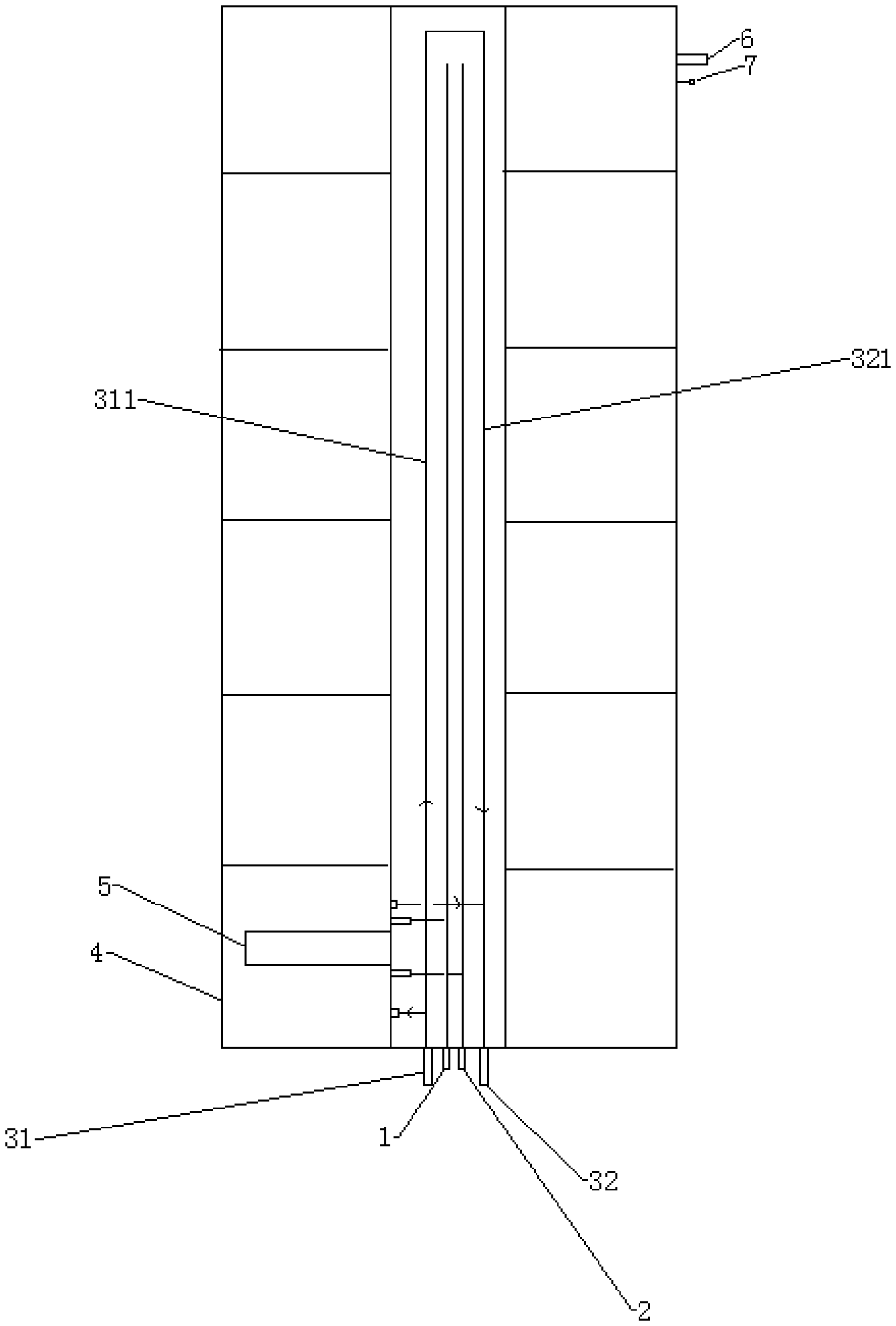
[0013] FIG. 2 illustrates a structural view of a battery heat dissipation module according to an embodiment of the present invention.
[0014] Description of the reference numerals: 1-main communication cable, 2-main power cable, 31-main inlet pipe inlet, 32-main outlet pipe outlet, 311-main inlet pipe, 312-main outlet pipe, 4-power heat dissipation module, 41-communication interface, 42-power interface, 431-liquid inlet, 432-liquid outlet, 5-battery unit, 6-expansing relief valve, 7-temperature detection sensor.
DETAILED DESCRIPTION OF THE PREFERRED EXAMPLES
[0015] To make the purpose, technical solutions and advantages of the present invention clearer, the embodiments of the present invention will be described below in detail in combination with the drawings. It should be noted that, in the case of no conflicts, the embodiments in the present invention and features in the embodiments can be combined mutually and arbitrarily.
[0016] According to an embodiment of the present invention, as shown in FIGS. 1 to 2, an immersed heat dissipation device for power battery comprises a battery heat dissipation module 4, a battery unit 5, a liquid refrigerant, a main inlet pipe 311 and a main outlet pipe 312, wherein the battery heat dissipation module 4 is a structure of sealed box that contains the liquid refrigerant, and a plurality of the battery heat dissipation modules 4 are connected to each other and arranged in the heat dissipation device for power battery. Each of the battery heat dissipation modules 4 is mounted therein with the battery unit 5, each of the battery units 5 is immersed in the liquid refrigerant in the battery heat dissipation module 4, and the liquid refrigerant is branched by the main inlet pipe 311 through the liquid inlet 431 to enter the battery heat dissipation module 4; the liquid refrigerant exchanges heat with the battery unit 5 at the battery heat dissipation module 4; the liquid refrigerant after the heat exchange flows into the main outlet pipe 321 through a liquid outlet 432, and flows out of the heat dissipation device for power battery.
[0017] The present invention adopts an immersed heat dissipation technology for power battery, which immerses a battery core of the power battery, i.e., the battery unit 5, into a coolant such that the battery unit 5 is cooled effectively and reliably, wherein the coolant is an insulating liquid refrigerant, such as an electronic fluorinated liquid, and if the insulated liquid refrigerant has a high thermal conductivity sufficient to cope with the heat generated by the battery unit 5, the insulated liquid refrigerant does not need to undergo a phase change. The heat dissipation device for power battery comprises a plurality of battery units 5, and the plurality of battery units 5 are connected in series; the battery unit 5 is entirely immersed in the coolant of the battery heat dissipation module 4 for discharging the heat generated by the battery core-battery unit 5 through the flowing of the coolant. The battery unit 5 is fixed to the box, which is provided respectively with a liquid inlet 431, a liquid outlet 432, a communication interface 41 and a power interface 42, wherein the liquid inlet 431 and the liquid outlet 432 are respectively connected to the main inlet pipe 311 and the main outlet pipe 321 to realize the circulation of the liquid refrigerant into and out, and complete the heat exchange with the battery unit 5. The communication interface 41 and the power interface 42 are respectively connected to the main communication cable 1 and the main power cable 2 for communication of control signals and transmission of power. The cryogenic coolant from the external coolant circulation system enters the main inlet pipe 311 from the main inlet pipe inlet 31, and enters the box of each of the battery heat dissipation modules 4 through a plurality of liquid inlets 431 that are connected in parallel/series, the coolant flows from one side of the battery heat dissipation module 4 and flows out from the other side of the battery heat dissipation module 4, during this process, the coolant exchanges heat with the battery unit 5 after being in direct contact with the battery unit, and the coolant flows heat from the liquid outlet 432 into the main outlet pipe 321 for being taken away by the main outlet pipe outlet 32.
[0018] The structure and working principle for each of the battery heat dissipation modules 4 are the same and the plurality of battery heat dissipation modules 4 are arranged in the entire battery pack through parallel or series connection to form a heat dissipation system for power battery pack.
[0019] At each of the battery heat dissipation modules 4, an expansion relief valve 6 and a temperature monitoring sensor 7 for monitoring the coolant pressure and temperature are provided.
[0020] While the embodiments of the present invention have been described above, the described embodiments are merely illustrative of the embodiments of the present invention, and are not intended to limit the present invention. Any modification and variation in the form and details of the embodiments may be made by those skilled in the art without departing from the spirit and scope of the invention, and maybe ought to fall within the scope of protection of the present application.
* * * * *
D00000
D00001
D00002
XML
uspto.report is an independent third-party trademark research tool that is not affiliated, endorsed, or sponsored by the United States Patent and Trademark Office (USPTO) or any other governmental organization. The information provided by uspto.report is based on publicly available data at the time of writing and is intended for informational purposes only.
While we strive to provide accurate and up-to-date information, we do not guarantee the accuracy, completeness, reliability, or suitability of the information displayed on this site. The use of this site is at your own risk. Any reliance you place on such information is therefore strictly at your own risk.
All official trademark data, including owner information, should be verified by visiting the official USPTO website at www.uspto.gov. This site is not intended to replace professional legal advice and should not be used as a substitute for consulting with a legal professional who is knowledgeable about trademark law.