Substrate Processing Apparatus And Method
Oosterlaken; Theodorus
U.S. patent application number 16/151074 was filed with the patent office on 2020-04-09 for substrate processing apparatus and method. The applicant listed for this patent is ASM IP Holding B.V.. Invention is credited to Theodorus Oosterlaken.
| Application Number | 20200111690 16/151074 |
| Document ID | / |
| Family ID | 70052336 |
| Filed Date | 2020-04-09 |


| United States Patent Application | 20200111690 |
| Kind Code | A1 |
| Oosterlaken; Theodorus | April 9, 2020 |
SUBSTRATE PROCESSING APPARATUS AND METHOD
Abstract
A substrate processing apparatus, provided with a substrate carrier support to support a substrate carrier thereon. The carrier support comprises a top support surface to support the substrate carrier; a thermally insulating body of thermally insulating material; and, a primary heater to heat the carrier support. The thermally insulating body is provided at least between the support surface and the primary heater.
| Inventors: | Oosterlaken; Theodorus; (Oudewater, NL) | ||||||||||
| Applicant: |
|
||||||||||
|---|---|---|---|---|---|---|---|---|---|---|---|
| Family ID: | 70052336 | ||||||||||
| Appl. No.: | 16/151074 | ||||||||||
| Filed: | October 3, 2018 |
| Current U.S. Class: | 1/1 |
| Current CPC Class: | H01L 21/67383 20130101; H01L 21/67757 20130101; H01L 21/68764 20130101; H01L 21/67306 20130101; H01L 21/67309 20130101; H01L 21/67103 20130101; H01L 21/67109 20130101 |
| International Class: | H01L 21/673 20060101 H01L021/673; H01L 21/67 20060101 H01L021/67; H01L 21/687 20060101 H01L021/687 |
Claims
1. A substrate processing apparatus, provided with a substrate carrier support to support a substrate carrier thereon, wherein the carrier support comprises: a top support surface to support the substrate carrier; a thermally insulating body of thermally insulating material; and, a primary heater to heat the carrier support, wherein the thermally insulating body is provided at least between the support surface and the primary heater.
2. The apparatus according to claim 1, wherein the carrier support comprises a side plate and the thermally insulating body is provided between the side plate and the primary heater.
3. The apparatus according to claim 1, wherein the carrier support comprises a bottom plate and the thermally insulating body is provided between the bottom plate and the primary heater.
4. The apparatus according to claim 1, wherein the thermally insulating body is substantially surrounding the primary heater.
5. The apparatus according to claim 1, wherein the thermally insulating body is thermally insulating the primary heater from its surrounding.
6. The apparatus according to claim 1, wherein the carrier support comprises a secondary heater between the support surface and the thermally insulating body.
7. The apparatus according to claim 6, wherein the primary heater comprises a heating power larger than the secondary heater.
8. The apparatus according to claim 1, wherein the primary heater has a power between 0.5 and 10 Kilowatt.
9. The apparatus according to claim 6, wherein the secondary heater has a power between 0.1 and 3 Kilowatt.
10. The apparatus according to claim 6, wherein the apparatus comprises a reaction chamber defining a reaction space and an opening via which a substrate carrier supported on the carrier support is moveable in said reaction space, wherein the apparatus comprises a heat controller to control the temperature of the carrier support, operably connected to the secondary heater and programmed to switch the secondary heater off when the substrate carrier is outside the reaction space.
11. The apparatus according to claim 10, wherein the heat controller is operably connected to the primary heater and programmed to keep the primary heater activated when the substrate carrier is outside the reaction space.
12. The apparatus according to claim 1, wherein the thickness of the thermally insulating body between the support surface and the primary heater is between 0.5 and 12 cm.
13. The apparatus according to claim 1, wherein the thermally insulating material insulates between 0.05 W/mK and 5 W/mK.
14. The apparatus according to claim 1, wherein the apparatus comprises a reaction chamber defining a reaction space and an opening via which a substrate carrier supported on the carrier support is moveable in said reaction space.
15. The apparatus according to claim 14, wherein the carrier support comprises an upper plate and a bottom plate, which plates are connected with a cylindrical side plate to define a generally cylindrical container and wherein an outer surface of the upper plate defines the support surface of the carrier support and the generally cylindrical container at least partially closes of the reaction space.
16. The apparatus according to claim 14, wherein the apparatus comprises an elevator constructed and arranged to move the carrier support in a vertical direction into the reaction chamber.
17. The apparatus according to claim 14, wherein the apparatus comprises a heat controller to control the temperature of the carrier support, operably connected to the primary heater and programmed to keep the primary heater activated when the substrate carrier is outside the reaction space.
18. The apparatus according to claim 1, further comprising a substrate carrier connected to the support surface of the carrier support and that is configured to hold at least one substrate.
19. The apparatus according to claim 18, wherein the substrate carrier is configured to hold between 10 and 300.
20. A method, comprising: providing a substrate processing apparatus according to claim 1; supporting a substrate carrier on the carrier support; and, exchanging at least one substrate of the substrate carrier, while heating the carrier support of the carrier support with the primary heater.
Description
FIELD
[0001] The present disclosure relates to the field of substrate processing apparatus and method. More in particular the disclosure relates to a substrate processing apparatus, provided with a substrate carrier support to support a substrate carrier thereon. The carrier support comprises a top support surface to support the substrate carrier; a thermally insulating body of thermally insulating material; and a primary heater to heat the carrier support.
BACKGROUND
[0002] The simultaneous processing of a plurality of substrates (e.g., semiconductor wafers) in a vertical batch furnace presents the problem of how to subject all wafers that are stacked into a substrate carrier (e.g., wafer boat) to substantially the same process conditions across their respective surface areas. One such process condition is the temperature uniformity. To obtain uniform processing results across the wafers of a batch, each of the wafers thereof may preferably be heated substantially uniformly to a common temperature by heating means disposed proximate a side wall of the reaction chamber and proximate a top wall of the reaction chamber.
[0003] As regards in particular the upper wafers in the substrate boat, the wafer-to-wafer temperature uniformity is generally not a significant problem, while the within-wafer temperature uniformity (due to asymmetries in the construction of the furnace) may be enhanced by an optional boat rotation mechanism. However, in a vertical batch furnace, the temperature uniformity of the lower wafers in the wafer boat may prove difficult to improve. This may be due to the fact that they are located closely to the relatively cold lower door zone of the reaction chamber. To mitigate the effect of their location, a pedestal supporting the wafer boat from below may be provided with a primary heater for heating the lower wafers.
[0004] When the substrates in the substrate carrier may be moved out of the reaction chamber to cool down and to be replaced with fresh substrates, the primary heater may be kept on to decrease the time necessary to stabilize the temperature when the substrate carrier is moved back in the reaction chamber for a next load. The primary heater may therefore also heat up the carrier support and surroundings when the carrier support is outside the reaction chamber. This heat up may lead to non-uniform heating of the substrate rack, slower cooldown of the substrates in the substrate support, and/or distortion of the airflow during handling of the substrates, which may be unwanted. Also the power consumption of the primary heater may be large when the carrier support is outside the reaction chamber with the primary heater remaining activated.
SUMMARY
[0005] It is an object to provide for an improved substrate processing apparatus and method.
[0006] According to an embodiment there is provided an improved substrate processing apparatus. The substrate processing apparatus may be provided with a substrate carrier support to support a substrate carrier thereon. The carrier support may comprise: a top support surface to support the substrate carrier; a thermally insulating body of thermally insulating material; and a primary heater to heat the carrier support. The thermally insulating body may be provided at least between the support surface and the primary heater.
[0007] According to a further embodiment there is provided a method, comprising:
[0008] providing a substrate processing apparatus provided with a substrate carrier support to support a substrate carrier thereon and comprising:
[0009] a top support surface to support the substrate carrier;
[0010] a thermally insulating body of thermally insulating material; and,
[0011] a primary heater to heat the carrier support, the thermally insulating body may be provided at least between the support surface and the primary heater, the method further comprising: [0012] supporting a substrate carrier on the carrier support; and, [0013] exchanging at least one substrate of the substrate carrier, while heating the carrier support of the substrate support with the primary heater.
[0014] For purposes of summarizing the invention and the advantages achieved over the prior art, certain objects and advantages of the invention have been described herein above. Of course, it is to be understood that not necessarily all such objects or advantages may be achieved in accordance with any particular embodiment of the invention. Thus, for example, those skilled in the art will recognize that the invention may be embodied or carried out in a manner that achieves or optimizes one advantage or group of advantages as taught or suggested herein without necessarily achieving other objects or advantages as may be taught or suggested herein.
[0015] All of these embodiments are intended to be within the scope of the invention herein disclosed. These and other embodiments will become readily apparent to those skilled in the art from the following detailed description of certain embodiments having reference to the attached figures, the invention not being limited to any particular embodiment(s) disclosed.
BRIEF DESCRIPTION OF THE DRAWINGS
[0016] While the specification concludes with claims particularly pointing out and distinctly claiming what are regarded as embodiments of the invention, the advantages of embodiments of the disclosure may be more readily ascertained from the description of certain examples of the embodiments of the disclosure when read in conjunction with the accompanying drawings, in which:
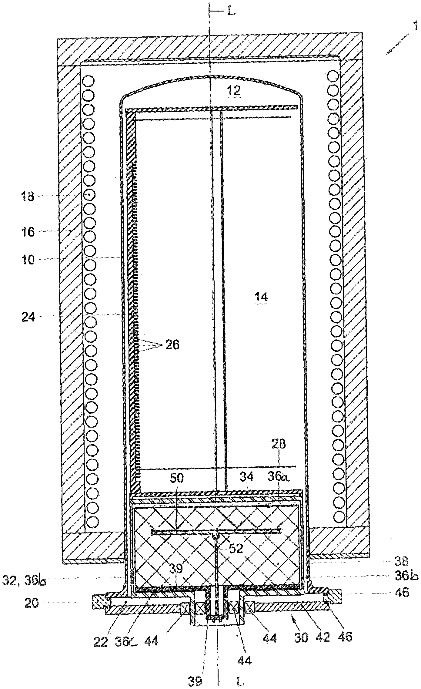
[0017] FIG. 1 is a schematic cross-sectional side view of a part of a vertical batch furnace with a primary heater according to an embodiment;
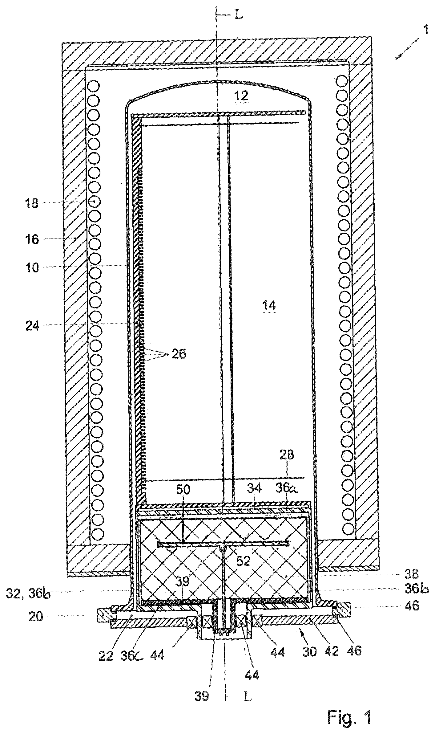
[0018] FIG. 2 is an enlarged cross-sectional side view of a substrate carrier support in a lower part of a reaction chamber with a primary heater according to a second embodiment;
[0019] FIGS. 3A to 3C schematically illustrate an exemplary vertical thermal furnace according to a third embodiment;
[0020] FIG. 4 is a schematic cross sectional side view of a substrate carrier support according to a fourth embodiment; and,
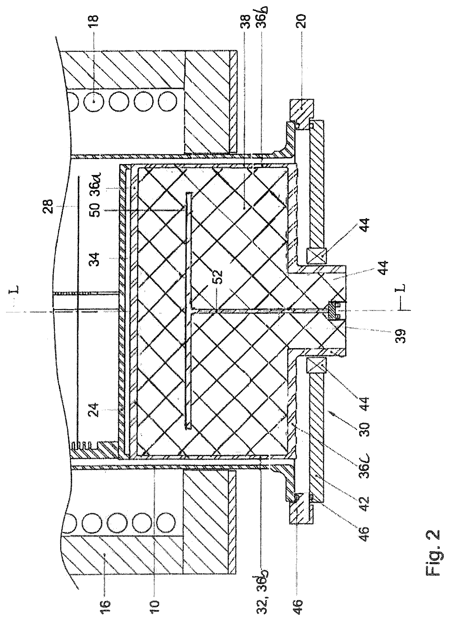
[0021] FIGS. 5A to 5C depict some results of the substrate carrier support according to FIG. 1, 2, 3A, 3B, 3C or 4 in comparison with the prior art.
DETAILED DESCRIPTION
[0022] Although certain embodiments and examples are disclosed below, it will be understood by those in the art that the invention extends beyond the specifically disclosed embodiments and/or uses of the invention and obvious modifications and equivalents thereof. Thus, it is intended that the scope of the invention disclosed should not be limited by the particular disclosed embodiments described below. The illustrations presented herein are not meant to be actual views of any particular material, structure, or device, but are merely idealized representations that are used to describe embodiments of the disclosure.
[0023] As used herein, the term "substrate" or "wafer" may refer to any underlying material or materials that may be used, or upon which, a device, a circuit, or a film may be formed. The term "semiconductor device structure" may refer to any portion of a processed, or partially processed, semiconductor structure that is, includes, or defines at least a portion of an active or passive component of a semiconductor device to be formed on or in a semiconductor substrate. For example, semiconductor device structures may include, active and passive components of integrated circuits, such as, for example, transistors, memory elements, transducers, capacitors, resistors, conductive lines, conductive vias, and conductive contact pads.
[0024] FIG. 1 schematically illustrate in a cross-sectional side view of a part of a vertical thermal processing furnace 1. The furnace 1 may be of a single or dual tube type and may include a generally bell jar-shaped reaction tube 10. The reaction tube 10 may delimit a reaction chamber 12 defining a reaction space 14 in which substrates, e.g., wafers may be processed.
[0025] The reaction tube 10 may be encircled or surrounded by a tube heater for heating wafers received in the reaction space 14, such as an electrically resistive heating coil 18 that is powered by an electrical power supply (not shown). The tube heater 18 may be secured to a thermally insulating sleeve 16 that surrounds or encircles the reaction tube 10. The reaction tube 10 may have a generally tubular, for example circular or polygonal, cross-sectional shape, and extend along a central axis L. As regards to the manufacturing material, the reaction tube 10 may be made of quartz, silicon carbide, silicon or another suitable heat resistant material. At its lower, open end, the reaction tube 10 may be supported on a flange 20 that defines a central furnace opening 22 via which a wafer boat 24 may enter and/or exit the reaction chamber 12.
[0026] The wafer boat 24 (substrate carrier), which may include a plurality of slots 26 (e.g., between 10 and 300, preferably between 25 and 250) for holding equally as many substrates, e.g., semiconductor wafers 28 (only one of which is shown in FIGS. 1 and 2), may be supported on a top support surface 34 of a substrate carrier support 32 (e.g., pedestal) of a support assembly 30. The substrate carrier support 32 may be mounted on a doorplate or seal cap 42 by means of a bearing 44, e.g., a roller-, fluid- or magnetic bearing.
[0027] An elevator or lift (not shown) may be used so that the carrier support 32 and the substrate carrier 24 may be raised into and lowered from the reaction chamber 12 at the beginning and end of a treatment, respectively. To ensure that the reaction chamber 12 can be sealed in a gas-tight manner, several elastomeric O-rings 46 may be employed in the lower part of the furnace 1, in particular between the reaction tube 10 and the flange 20, and between the flange 20 and the door plate 42.
[0028] The substrate carrier support 32 may accommodate a primary heater 50. The primary heater 50 may have a power between 0.5 and 10 Kilowatt, preferably between 1 and 6 Kilowatt, and most preferably between 2 and 4 Kilowatt. The carrier support 32 may be at least partly filled with a thermally insulating body 38 of thermally insulating material. The thermally insulating material insulates between 0.05 W/mK and 5 W/mK, or 0.2 to 2 W/mK, 0.3-1 W/mK.
[0029] The thermally insulating body 38 may be provided between the top support surface 34 and the primary heater 50 to serve as a heat shield when the substrates in the substrate carrier 24 may be moved out of the reaction chamber 12 to cool down and to be replaced with fresh substrates. The primary heater 50 may then be kept activated to decrease the time necessary to stabilize the temperature when the substrate carrier 24 is moved back in the reaction chamber 12 with a next load. The thickness of the thermally insulating body between the support surface 34 and the primary heater 50 may between 0.5 and 12 cm, preferably between 1 and 8 cm and most preferably between 2 and 6 cm.
[0030] The insulating body 38 of thermally insulating material may reduce the issue that the primary heater 50 may heat up the carrier support 32 and surroundings when the carrier support 32 is outside the reaction chamber 12. Such heating up may lead to non-uniform heating of the substrate carrier and/or a slower cooldown of the substrates in the substrate carrier. Further it may lead to distortion of the airflow during handling of the substrates, which may be unwanted because the distortion may create upward flow while a downward flow may be preferred to avoid particle contamination on the substrates 28. Also, the power consumption of the primary heater 50 may decrease by the insulation when the carrier support 32 is outside the reaction chamber.
[0031] The carrier support 32 may comprises a side plate 36b. The thermally insulating body 38 may be provided between the side plate 36b and the primary heater 50 to reduce heat loss through the side plate 36b when the carrier support is outside the reaction chamber 12. It may also reduce heat loss through the lower portion of the furnace 1, e.g., the door plate 42 and the flange 20 when the reaction chamber 12 is closed.
[0032] The carrier support 32 may comprise a bottom plate 36c and the thermally insulating body 38 may be provided between the bottom plate 36c and the primary heater 50 to reduce heat loss when the carrier support 32 is outside the reaction chamber 12. It may also reduce heat loss through the lower portion of the furnace 1, e.g., the door plate 42 and the flange 20 when the reaction chamber is closed. The insulating material 38 may rest on a base plate 39 that is moveable (rotatable) relative to the walls of container 36a, b, c.
[0033] Underneath the support surface 34, the primary heater 50 may spread out to cover an area that may be smaller or approximately equal to the area of the top support surface 34. This may be required in order to heat (the lower) wafers 28 in the substrate carrier 24 across their entire surface.
[0034] The primary heater 50 may be fixed within, and substantially surrounded by the insulating body 38. An upwardly extending connection portion 52 for (electrically) connecting to the primary heater 50 may be embedded in the thermally insulating body 38 as well. The thermally insulating body 38 may be substantially thermally insulating the primary heater 50 from its surrounding.
[0035] A motor drive may be provided to rotate the carrier support 32 around the central axis L of the reaction chamber 12. Since the substrate carrier 24 may be connected to the carrier support 32, it may rotate in unison therewith. The door plate 42 and the rest of the fixed structure of the furnace 1, e.g., the reaction tube 10 and the thermally insulating sleeve 16, may remain stationary during rotation of container 36a, b, c of the carrier support 32. Base plate 39, insulating body 38, and primary heater 50 may also remain stationary during rotation of container 36. This may be done by fixedly or rigidly connecting base plate 39 with insulating body 38 and primary heater 50 to a stationary part of the furnace 1 that is non-rotatably mounted with respect to the rotation axis L of the carrier support 32, such as the doorplate 42.
[0036] Alternatively, the rotatable mounted support heater 50 may also be provided with a dedicated motor drive. The motor drive may be configured to rotate the primary heater 50 at a different angular velocity or even in opposite direction than that at which the substrate support 32 is driven.
[0037] The carrier support 32 may comprise an upper plate 36a, a cylindrical side plate 36b and a bottom plate 36c, which plates may be interconnected to define a generally cylindrical container 36. An outer surface of the upper plate 36a may define the support surface 34 of the carrier support 30. The container 36a, b, c may extend between the upper plate 36a and the bottom plate 36c, which body accommodates at least part of the primary heater 50.
[0038] FIGS. 2 to 4 schematically illustrate exemplary vertical thermal furnace according to embodiments. In order not to obscure the discussion of FIGS. 2 to 4, same reference numerals as in FIG. 1 are used for similar components. It is understood, however, that the physical properties of, and relationships between, the various components depicted in FIGS. 2 to 4 may differ from those in FIG. 1. Other components of the vertical thermal furnace shown in FIGS. 2 to 4 may generally be identical to corresponding components of the above-described conventional furnace 1.
[0039] FIG. 2 is an enlarged cross-sectional side view of a substrate carrier support in a lower part of a reaction chamber with a primary heater 50 according to a second embodiment. The primary heater 50 may be rotatable mounted in the second embodiment by the primary heater 50 being mechanically coupled to the rotatable carrier support 32 so that it may be easier to construct.
[0040] The substrate carrier support 32 may accommodate the primary heater 50 and may at least partly be filled with a thermally insulating body 38 of thermally insulating material. The primary heater 50 may have a power between 0.5 and 10 Kilowatt, preferably between 1 and 6 Kilowatt, and most preferably between 2 and 4 Kilowatt. The thermally insulating material insulates between 0.05 W/mK and 5 W/mK, or 0.2 to 2 W/mK, 0.3-1 W/mK.
[0041] The thermally insulating body 38 may be provided between the top support surface 34 and the primary heater 50 to serve as an insulator when the substrates in the substrate carrier 24 may be moved out of the reaction chamber 12 to cool down and to be replaced with fresh substrates. The thickness of the thermally insulating body between the support surface 34 and the primary heater 50 may between 0.5 and 12 cm, preferably between 1 and 8 cm and most preferably between 2 and 6 cm.
[0042] The primary heater 50 may be kept activated to decrease the time necessary to stabilize the temperature when the substrate carrier 24 is moved back in the reaction chamber 12 with a next load. The insulating body 38 of thermally insulating material may partially prevent that the primary heater 50 heats up the carrier support 32 and surroundings when the carrier support 32 is outside the reaction chamber 12. Such heating up may otherwise lead to non-uniform heating of the substrate carrier, slower cooldown of the substrates in the substrate carrier, and/or distortion of the airflow during handling of the substrates which may be unwanted. Also the power consumption of the primary heater 50 may decrease by the insulation when the carrier support 32 is outside the reaction chamber.
[0043] The carrier support 32 may comprises a side plate 36b. The thermally insulating body 38 may be provided between the side plate 36b and the primary heater 50 to reduce heat loss through the side plate 36b when the carrier support is outside the reaction chamber 12. Also heat loss through the lower portion of the furnace 1 may be reduced when the reaction chamber 12 is closed.
[0044] The carrier support 32 may comprise a bottom plate 36c and the thermally insulating body 38 may be provided between the bottom plate 36c and the primary heater 50 to reduce heat loss through the bottom plate 36c when the carrier support 32 is outside the reaction chamber 12. Also heat loss through the door plate 42 and the flange 20 may be reduced when the reaction chamber is closed. Underneath the support surface 34, the primary heater 50 may spread out to cover an area that may be smaller or approximately equal to the area of the top support surface 34. The primary heater 50 may be able to heat (the lower) wafers 28 in the substrate carrier 24 across their entire surface.
[0045] The primary heater 50 may be fixed within, and substantially surrounded by the insulating body 38. An upwardly extending connection portion 52 for (electrically) connecting to the primary heater 50 may be embedded in the thermally insulating body 38 as well. The thermally insulating body 38 may be substantially thermally insulating the primary heater 50 from its surrounding.
[0046] A motor drive may be provided to rotate the carrier support 32 around the central axis L of the reaction chamber 12. The door plate 42 and the rest of the fixed structure of the furnace 1, e.g., the reaction tube 10 and the thermally insulating sleeve 16, may remain stationary during rotation of container 36a, b, c of the carrier support 32. Insulating material 38 and primary heater 50 may rotate with the container 36. This may be done by fixedly or rigidly connecting container 36 with insulating body 38 and primary heater 50. The substrate carrier support 32 may be mounted on a doorplate or seal cap 42 by means of a bearing 44, e.g., a roller-, fluid- or magnetic bearing. The connection portion 52 for (electrically) connecting to the primary heater 50 may be connected with a connector that allows rotation.
[0047] In FIG. 3A, substrates in the substrate carrier 24 supported on the carrier support 32 may be processed in the reaction chamber 12. The reaction chamber 12 may be closed with the door plate 42 and the substrates may be heated with the tube heater (not shown) and the support heater 50.
[0048] After the substrates 28 have been processed in the reaction chamber 12 the substrates in the carrier support 32 may be moved out of the reaction chamber 12 to cool down (see FIG. 3B). The apparatus may therefor comprise an actuator constructed and arranged to move at least one of the heat shield and the carrier support 32 with respect to each other. For example the apparatus may comprises an elevator 59 constructed and arranged to move the carrier support 32 in a vertical direction in and out of the reaction chamber 12. The elevator 59 may have a moving portion 63 which may be moveable along a spindle 65 driven by a motor 67.
[0049] As shown in FIG. 3C, the substrate carrier 24 may be completely moved out of the reaction chamber 12. Subsequently the reaction chamber 12 may be closed with a reaction chamber door 35. With the reaction chamber door 35 closed it may be easier to keep the reaction chamber 12 at the correct temperature while not heating the surrounding too much.
[0050] FIG. 4 is a schematic cross sectional side view of a substrate carrier support according to a third embodiment. The substrate carrier support 32 may accommodate a primary heater 50 and may at least partly be filled with a thermally insulating body 38 of thermally insulating material. The thermally insulating material may insulate between 0.05 W/mK and 5 W/mK, or 0.2 to 2 W/mK, 0.3-1 W/mK.
[0051] The thermally insulating body 38 may be provided between the top support surface 34 and the primary heater 50 to serve as a heat shield when the substrates in the substrate carrier may be moved out of the reaction chamber to cool down and to be replaced with fresh substrates. The thickness of the thermally insulating body 38 between the support surface 34 and the primary heater 50 may between 0.5 and 12 cm, preferably between 1 and 8 cm and most preferably between 2 and 6 cm.
[0052] The primary heater 50 may be kept activated to decrease the time necessary to stabilize the temperature when the substrate carrier is moved back in the reaction chamber with a next load. The insulating body 38 of thermally insulating material may partially prevent that the primary heater 50 heats up the carrier support and surroundings when the carrier support 32 is outside the reaction chamber. Such heating up may otherwise lead to non-uniform heating of the substrate carrier, slower cooldown of the substrates in the substrate carrier, and/or distortion of the airflow during handling of the substrates which may be unwanted. Also the power consumption of the primary heater 50 may decrease by the insulation when the carrier support 32 is outside the reaction chamber.
[0053] The carrier support 32 may comprises a side plate 36b. The thermally insulating body 38 may be provided between the side plate 36b and the primary heater 50 to reduce heat loss through the side plate 36b when the carrier support 32 is outside the reaction chamber 12. It may also reduce heat loss through the lower portion of the furnace when the reaction chamber is closed.
[0054] The carrier support 32 may comprise a bottom plate 36c and the thermally insulating body 38 may be provided between the bottom plate 36c and the primary heater 50 to reduce heat loss when the carrier support 32 is outside and or inside the reaction chamber. Underneath the support surface 34, the primary heater 50 may spread out to cover an area that may be smaller or approximately equal to the area of the top support surface 34.
[0055] The primary heater 50 may be fixed within, and substantially surrounded by the insulating body 38. An upwardly extending connection portion for electrically connecting to the primary heater may be embedded in the thermally insulating body. The thermally insulating body 38 may be substantially thermally insulating the primary heater 50 from its surrounding.
[0056] The carrier support 32 may comprises a secondary heater 71 between the support surface 34 and the thermally insulating body 38. The secondary heater 71 may have a surface forming the support surface 34 or may be thermally very well connected to the support surface 34.
[0057] The secondary heater 71 may be embedded a little into the thermally insulating body 38. This may reduce heat loss to the side plate 36b close to the secondary heater 71.
[0058] The primary heater 50 may have a heating power larger than the secondary heater 71. The primary heater 50 may have a power between 0.5 and 10 Kilowatt, preferably between 1 and 6 Kilowatt, and most preferably between 2 and 4 Kilowatt. The secondary heater 71 may have a power between 0.1 and 3 Kilowatt, preferably between 0.3 and 2 Kilowatt, and most preferably between 0.5 and 1.2 Kilowatt.
[0059] The apparatus may have a reaction chamber (see FIGS. 1, 2, 3A, 3B and 3C) defining a reaction space and an opening via which a substrate carrier supported on the carrier support is moveable in said reaction space. The apparatus may comprises a heat controller 73 to control the temperature of the carrier support 32.
[0060] The heat controller 73 may be operably connected to the secondary heater 71 with a secondary heater connector 75 and programmed to switch the secondary heater 71 off when the substrate carrier 24 is outside the reaction space. The heat controller 73 may be programmed to switch the secondary heater 71 on when the substrate carrier 32 is inside the reaction space. By this switching of the secondary heater 71 heating up, the environment by the secondary heater 71 may be reduced.
[0061] The heat controller 73 may be operably connected to the primary heater 50 as well. The heat controller 73 may be operably connected to the primary heater 50 with a primary heater connector 77 and programmed to keep the primary heater activated when the substrate carrier 24 is outside the reaction space. The time necessary for the temperature in the carrier support 32 to stabilize may be reduced by leaving the primary heater also on when the carrier support is outside the reaction chamber.
[0062] The heat controller 73 as depicted may be provided inside the carrier support and connected to the rest of the apparatus with a connection portion 52. The connection portion 52 and the primary and secondary heater connectors 73, 75 are shown as single cables however the cables may be provided with double wiring. The heat controller 73 may also be provided in other parts of the apparatus and connected with the primary and secondary heater connectors 73, 75 to the primary and secondary heaters.
[0063] The primary heater 50 may spread out to cover an area that may be smaller or equal to the area of the top support surface 34. The secondary heater 71 may spread out to cover an area that may be smaller or approximately equal to the area of the top support surface 34 as well. It may thereby be able to heat (the lower) wafers 28 in the substrate carrier 24 across their entire surface. The area of the primary heater 50 may be larger than the area of the secondary heater 71.
[0064] In order to optimize the temperature uniformity of the lower wafers further, primary heater 50 and/or secondary heater 71 may comprise more than one zone. The heat generating portion of each zone may be extending over a part of the top support surface 34. E.g., a first zone may extend over a central region of support surface 34 and a second zone may extend over an outer region of support surface 34.
[0065] In another embodiment a first zone may extend over a first tangentially extending region of support surface 34 and a second zone may extend over a second tangentially extending region of support surface 34. Each zone may comprise wiring to the heat controllers 73 to allow for individual control.
Experimental Results
[0066] FIGS. 5B and 5C depict some results of the substrate carrier support according to the embodiments in comparison to embodiments according to the prior art. The figures show what the temperature distribution over the height of the carrier support from the top surface 34 to the bottom plate 36c is over time. The line depicted by 0 depicts the temperature at the lowest level, e.g., the bottom plate 36c of the carrier support while the line 0.1 depicts the temperature at the highest level, e.g., the carrier support surface 34 of the carrier support. The lines 0.01 to 0.09 depict the temperature of levels equally spaced through the height of the carrier support.
[0067] FIG. 5A shows what the temperature distribution is over the height of the carrier support when the carrier support is left to cool down outside the reactor for about 1 hour and the primary heater is switched off during this period. What is shown is that the carrier support at all levels completely cools down. When doing the next load the carrier support is moved up and the primary heater may be switched on again. The stabilization of the temperature, which is shown by all the lines of the temperature over time becoming horizontal may not be accomplished within 1 hour which is by far to long for efficiently operating a vertical furnace.
[0068] In FIG. 5B, it is shown what the temperature distribution is over the height of the carrier support when the carrier support has a primary heater and an insulating body according to FIG. 1, 2, 3A, 3B or 3C. The primary heater 50 may be kept on when the carrier support is moved out of the reactor. What is shown is that the carrier support at level 0.08 to level 0.1 may cool down a bit but far less than in FIG. 5A. Further level 0.7 (e.g., the level of the primary heater 50) to level 0 (e.g., the level of the bottom plate 36c) remain at the same temperature by the primary heater 50 kept on.
[0069] When moving the next load in the reactor, the stabilization of the temperature, which is shown by all the lines of the temperature over time becoming horizontal, may be accomplished within minutes since most of the carrier support was still at the same temperature. This makes it possible to operate the vertical furnace more quick. In this example only a 3.2 kW primary heater may be used, which shows the efficiency of this solution.
[0070] In FIG. 5C, it is shown what the temperature distribution over the height of the carrier support may be when the carrier support has a primary heater and a secondary heater according to FIG. 4. The primary heater may be kept on when the carrier support is moved out of the reactor for a next load while the secondary heater may be temporarily switched off. What is shown is that the carrier support at level 0.08 to level 0.1 (e.g., the level of the secondary heater 71) may cool down a bit faster than in FIG. 5B. Further level 0.7 (e.g., the level of the primary heater 50) to level 0 (e.g., the level of the bottom plate 36c) may remain at the same temperature because the primary heater may remain on.
[0071] When moving the next load in the reactor and switching on the secondary heater 71, again the stabilization of the temperature, which is shown by all the lines of the temperature over time becoming horizontal, may be accomplished also within minutes which is much more quick than the example of FIG. 5A. In this example a secondary heater of 0.9 kW, and a primary heater of 2.5 kW may be used. The dissipated power in this example may be only 20% of the pure secondary heater doing the same which proves the efficiency of this solution.
[0072] Although illustrative embodiments of the present invention have been described above, in part with reference to the accompanying drawings, it is to be understood that the invention is not limited to these embodiments. Variations to the disclosed embodiments can be understood and effected by those skilled in the art in practicing the claimed invention, from a study of the drawings, the disclosure, and the appended claims.
[0073] Reference throughout this specification to "one embodiment" or "an embodiment" means that a particular feature, structure or characteristic described in connection with the embodiment is included in at least one embodiment of the present invention. Thus, the appearances of the phrases "in one embodiment" or "in an embodiment" in various places throughout this specification are not necessarily all referring to the same embodiment. Furthermore, it is noted that particular features, structures, or characteristics of one or more embodiments may be combined in any suitable manner to form new, not explicitly described embodiments.
* * * * *
D00000
D00001
D00002
D00003
D00004
D00005
D00006
D00007
XML
uspto.report is an independent third-party trademark research tool that is not affiliated, endorsed, or sponsored by the United States Patent and Trademark Office (USPTO) or any other governmental organization. The information provided by uspto.report is based on publicly available data at the time of writing and is intended for informational purposes only.
While we strive to provide accurate and up-to-date information, we do not guarantee the accuracy, completeness, reliability, or suitability of the information displayed on this site. The use of this site is at your own risk. Any reliance you place on such information is therefore strictly at your own risk.
All official trademark data, including owner information, should be verified by visiting the official USPTO website at www.uspto.gov. This site is not intended to replace professional legal advice and should not be used as a substitute for consulting with a legal professional who is knowledgeable about trademark law.