Aerial Roof Estimation System And Method
Pershing; Chris T. ; et al.
U.S. patent application number 16/706047 was filed with the patent office on 2020-04-09 for aerial roof estimation system and method. The applicant listed for this patent is Eagle View Technologies, Inc.. Invention is credited to Dave Carlson, Chris T. Pershing.
| Application Number | 20200111113 16/706047 |
| Document ID | / |
| Family ID | 39873115 |
| Filed Date | 2020-04-09 |


| United States Patent Application | 20200111113 |
| Kind Code | A1 |
| Pershing; Chris T. ; et al. | April 9, 2020 |
AERIAL ROOF ESTIMATION SYSTEM AND METHOD
Abstract
Image analysis systems and methods are disclosed including a computer system executing instructions to receive a plurality of aerial image files of a building having a roof including a first aerial image file taken from a first viewpoint of the building and a second aerial image file taken from a second viewpoint of the building different than the first viewpoint; determine a pitch and an area of one or more roof sections based on image analysis performed on the aerial image files, wherein the image analysis comprises constructing a three-dimensional model of one or more roof sections; generate a roof report that includes the pitch and the area of the one or more roof sections based on the determined pitch and area of the one or more roof sections, wherein the pitch is indicative of a vertical rise of a roof section over a horizontal run of the roof section.
| Inventors: | Pershing; Chris T.; (Redmond, WA) ; Carlson; Dave; (Anaheim, CA) | ||||||||||
| Applicant: |
|
||||||||||
|---|---|---|---|---|---|---|---|---|---|---|---|
| Family ID: | 39873115 | ||||||||||
| Appl. No.: | 16/706047 | ||||||||||
| Filed: | December 6, 2019 |
Related U.S. Patent Documents
| Application Number | Filing Date | Patent Number | ||
|---|---|---|---|---|
| 13371271 | Feb 10, 2012 | 10528960 | ||
| 16706047 | ||||
| 12148439 | Apr 17, 2008 | 8145578 | ||
| 13371271 | ||||
| 60925072 | Apr 17, 2007 | |||
| Current U.S. Class: | 1/1 |
| Current CPC Class: | G06Q 30/0283 20130101; G06Q 30/0206 20130101; G06Q 50/16 20130101; G06Q 10/00 20130101; G06Q 40/08 20130101 |
| International Class: | G06Q 30/02 20060101 G06Q030/02; G06Q 50/16 20060101 G06Q050/16; G06Q 40/08 20060101 G06Q040/08; G06Q 10/00 20060101 G06Q010/00 |
Claims
1. A roof estimation computer system, comprising: at least one computer processor; one or more non-transitory memory storing a set of instructions that when executed by the at least one computer processor cause the at least one computer processor to: receive a plurality of aerial image files of a building having a roof including a first aerial image file taken from a first viewpoint of the building and a second aerial image file taken from a second viewpoint of the building different than the first viewpoint, wherein at least one of the first aerial image file and the second aerial image file has calibration information associated with the at least one of the first aerial image file and the second aerial image file; determine a pitch and an area of one or more roof sections of the roof based on an image analysis performed on the plurality of aerial image files, wherein the image analysis comprises: constructing a three-dimensional model of one or more roof sections by: calibrating at least one of the first and second aerial image files using the calibration information associated with the at least one of the first aerial image file and the second aerial image file to convert a distance in pixels between two points on the respective aerial image file into a physical length; identifying common reference points depicted in at least the first aerial image file and the second aerial image file; identifying, for all such reference points, a location in three- dimensional space by triangulating the reference points by projecting a first line originating from the first viewpoint through one of the reference points and a second line originating from the second viewpoint through the same reference point and determining an intersection of the first and second lines; and determining physical length between at least two of the reference points in three-dimensional space based at least in part on the calibration; generate a roof report that includes the pitch and the area of the one or more roof sections based on the determined pitch and area of the one or more roof sections, wherein the pitch is indicative of a vertical rise of a roof section over a horizontal run of the roof section; and output the roof report having the determined pitch therein.
2. The roof estimation computer system of claim 1, wherein the roof report includes an orientation and a geometrical shape of the one or more roof sections.
3. The roof estimation computer system of claim 2, wherein the roof report includes an estimate of a number and type of solar panels to be installed on the roof of the building based on at least one of the area of the one or more roof sections, the geometric shape of the one or more roof sections, and the orientation of the one or more roof sections.
4. The roof estimation computer system of claim 1, wherein the roof report includes one or more top plan views of the three-dimensional model of the roof annotated with numerical values that indicate a corresponding slope, area, and length of edges of at least two of the one or more roof sections using at least two different indicia for different types of roof properties.
5. The roof estimation computer system of claim 1, wherein the roof report includes one or more top plan views of the three-dimensional model of the roof and includes numerical values on the one or more top plan views that are numerical values of a corresponding slope, area, or length of an edge of at least one of the one or more roof sections.
6. The roof estimation computer system of claim 5, wherein the roof report indicates whether each of the numerical values are either of the corresponding, slope, area or length of an edge of the one or more roof sections at least in part by where the numerical values are placed on the top plan view relative to the one or more roof sections.
7. The roof estimation computer system of claim 6, wherein at least two of the numerical values are placed adjacent to corresponding edges of the one or more roof sections on the top plan view to indicate the at least two of the numerical values are each lengths of the corresponding edges to which the at least two of the numerical values are adjacent.
8. The roof estimation computer system of claim 6, wherein at least one of the numerical values is placed generally in a center of the one or more roof sections on the top plan view to indicate the at least one of the numerical values is an area of one or more roof sections.
9. The roof estimation computer system of claim 5, wherein the roof report indicates whether at least two of the numerical values are either of the corresponding slope of the one or more roof sections, area of the one or more roof sections or length of an edge of the one or more roof sections at least in part by an annotation next to each of the at least two numerical values.
10. The roof estimation computer system of claim 9, wherein the at least two of the numerical values are of the corresponding slope of the one or more roof sections and the annotation is an arrow adjacent to the numerical value to indicate the numerical value is of the corresponding slope of the one or more roof sections.
11. One or more non-transitory computer memory storing a set of instructions that when executed by at least one computer processor cause the at least one computer processor to: receive a plurality of aerial image files of a building having a roof including a first aerial image file taken from a first viewpoint of the building and a second aerial image file taken from a second viewpoint of the building different than the first viewpoint, wherein at least one of the first aerial image file and the second aerial image file has calibration information associated with the at least one of the first aerial image file and the second aerial image file; determine a pitch and an area of one or more roof sections of the roof based on an image analysis performed on the plurality of aerial image files, wherein the image analysis comprises: constructing a three-dimensional model of one or more roof sections by: calibrating at least one of the first and second aerial image files using the calibration information associated with the at least one of the first aerial image file and the second aerial image file to convert a distance in pixels between two points on the respective aerial image file into a physical length; identifying common reference points depicted in at least the first aerial image file and the second aerial image file; identifying, for all such reference points, a location in three-dimensional space by triangulating the reference points by projecting a first line originating from the first viewpoint through one of the reference points and a second line originating from the second viewpoint through the same reference point and determining an intersection of the first and second lines; and determining physical length between at least two of the reference points in three-dimensional space based at least in part on the calibration; generate a roof report that includes the pitch and the area of the one or more roof sections based on the determined pitch and area of the one or more roof sections, wherein the pitch is indicative of a vertical rise of a roof section over a horizontal run of the roof section; and output the roof report having the determined pitch therein.
12. The non-transitory computer memory of claim 11, wherein the roof report includes an orientation and a geometrical shape of the one or more roof sections.
13. The non-transitory computer memory of claim 12, wherein the roof report includes an estimate of a number and type of solar panels to be installed on the roof of the building based on at least one of the area of the one or more roof sections, the geometric shape of the one or more roof sections, and the orientation of the one or more roof sections.
14. The non-transitory computer memory of claim 11, wherein the roof report includes one or more top plan views of the three-dimensional model of the roof annotated with numerical values that indicate a corresponding slope, area, and length of edges of at least two of the one or more roof sections using at least two different indicia for different types of roof properties.
15. The non-transitory computer memory of claim 11, wherein the roof report includes one or more top plan views of the three-dimensional model of the roof and includes numerical values on the one or more top plan views that are numerical values of a corresponding slope, area, or length of an edge of at least one of the one or more roof sections.
16. The non-transitory computer memory of claim 15, wherein the roof report indicates whether each of the numerical values are either of the corresponding, slope, area or length of an edge of the one or more roof sections at least in part by where the numerical values are placed on the top plan view relative to the one or more roof sections.
17. The non-transitory computer memory of claim 16, wherein at least two of the numerical values are placed adjacent to corresponding edges of the one or more roof sections on the top plan view to indicate the at least two of the numerical values are each lengths of the corresponding edges to which the at least two of the numerical values are adjacent.
18. The non-transitory computer memory of claim 16, wherein at least one of the numerical values is placed generally in a center of the one or more roof sections on the top plan view to indicate the at least one of the numerical values is an area of one or more roof sections.
19. The non-transitory computer memory of claim 15, wherein the roof report indicates whether at least two of the numerical values are either of the corresponding slope of the one or more roof sections, area of the one or more roof sections or length of an edge of the one or more roof sections at least in part by an annotation next to each of the at least two numerical values.
20. The non-transitory computer memory of claim 19, wherein the at least two of the numerical values are of the corresponding slope of the one or more roof sections and the annotation is an arrow adjacent to the numerical value to indicate the numerical value is of the corresponding slope of the one or more roof sections.
Description
CROSS-REFERENCE TO RELATED APPLICATIONS
[0001] This application is a continuation of U.S. patent application Ser. No. 13/371,271, filed on Feb. 10, 2012, now pending, which is a continuation of, and claims priority to, U.S. patent application Ser. No. 12/148,439, filed Apr. 17, 2008, which issued as U.S. Pat. No. 8,145,578, which claims benefit of U.S. Provisional Application No. 60/925,072 filed on Apr. 17, 2007, all of which applications are incorporated herein by reference in their entirety.
BACKGROUND OF THE INVENTION
Field of the Invention
[0002] This invention relates to systems and methods for estimating construction projects, and more particularly, to such systems and methods that allow estimates involving roofs on buildings to be created remotely.
Description of the Related Art
[0003] The information provided below is not admitted to be part of the present invention, but is provided solely to assist the understanding of the reader.
[0004] Homeowners typically ask several roofing contractors to provide written estimates to repair or replace a roof on a house. Heretofore, the homeowners would make an appointment with each roofing contractor to visit the house to determine the style of roof, take measurements, and to inspect the area around the house for access and cleanup. Using this information, the roofing contractor then prepares a written estimate and then timely delivers it to the homeowner. After receiving several estimates from different roofing contractors, the homeowner then selects one.
[0005] There are factors that impact the roofing contractor's ability to provide a timely written estimate. One factor is the size of the roof contractor's company and the location of the roofing jobs currently underway. Most roof contractors provide roofing services and estimates to building owners over a large geographical area. Larger roof contractor companies hire one or more trained individuals who travel throughout the entire area providing written estimates. With smaller roofing contractors, the owner or a key trained person is appointed to provide estimates. With both types of companies, roofing estimates are normally scheduled for buildings located in the same area on a particular day. If an estimate is needed suddenly at a distant location, the time for travel and the cost of commuting can be prohibitive. If the roofing contractor is a small company, the removal of the owner or key person on a current job site can be time prohibitive.
[0006] Another factor that may impact the roofing contractor's ability to provide a written estimate is weather and traffic.
[0007] Recently, solar panels have become popular. In order to install solar panels, the roof's slope, geometrical shape, and size as well as its orientation with respect to the sun all must be determined in order to provide an estimate of the number and type of solar panels required. Unfortunately, not all roofs on a building are proper size, geometrical shape, or orientation for use with solar panels.
[0008] What is needed is a system that allows a roof to be quickly and easily measured and that does not require the estimator to physically travel to the building to take measurements. Such measurements can then be used to prepare an estimate to repair or replace the roof or install equipment thereon.
SUMMARY OF THE INVENTION
[0009] These and other objects are met by the system and method disclosed herein that allows a company that needs the sizes, dimensions, slopes and orientations of the roof sections on a building in order to provide a written estimate. The system includes the use of a roof estimating software program and a location-linked, image file database. During use, the physical address or location information of the building is inputted into the program which then presents aerial images of roof sections on the building at the specific address location. An overhead aircraft, a balloon, or satellite may produce the aerial images. An image analysis and calibration is then performed either manually or via a software program that determines the geometry, the slopes, the pitch angles, and the outside dimensions of the roof sections. The images may also include the land surrounding the roof sections and building which the estimating company can use to factor in additional access or clean-up costs.
[0010] In the first embodiment of the system, the roof company is contacted by a potential customer requesting an estimate for repair or replacement of a roof on their building. The roof company uses a local computer with an estimating software program loaded into its working memory to access an image file database located on the computer or on a remote server connected via a wide area network to the local computer. The image file database contains image files of various buildings in the roof company's service area. When a request for an estimate is received from a potential customer, the roof company enters the customer's address into the software program and aerial images of the building are then presented to the roof company. The roof company then manually measures or uses a roof estimation software program to determine the slopes, dimensions, and other relevant geometric information of the roof sections on the buildings. From these determinations, the overall shape, slopes and square footage of the roof sections are determined and a report is produced. After the report has been prepared, the images are reviewed again for special access and cleanup tasks which can be added to the final estimate before transmission to the potential customer.
[0011] In another embodiment, the roof estimate software program and image file database are both stored on one or more remote computers and accessed by the roof company via a wide area network. The roof company uses an assigned user name and password to log onto the website and access the computer. After logging on, the roof company logs then submits the new customer's address, other relevant job related information, and a request for a report from the roof estimation service. An estimation service associated with the website uses the address information to obtain the images of the roof sections on the building(s) and uses the roof estimation software program and calibration module to determine the relevant geometry, pitch angles, dimensions, and surface areas of the building's roof. The service then produces and sends a report to the roof company. The company then uses the report to prepare a final estimate that is then delivered to the potential customer.
[0012] In another embodiment of the system, a roof estimating website is designed to receive requests for roof estimates directly from potential customers in a region. The estimation service that owns and operates the website is associated with various roof companies that provide roof-related services in the region serviced by the website. When a potential customer contacts the website and requests an estimate for a roof repair, replacement or installation of equipment, the potential customer's name, address, and contact information is first submitted on the website. The estimation service representative enters the address of the building into the roof estimation software program. The aerial images of the buildings are then obtained and analyzed by the service representative to extract the relevant geometric information about the structures. A report containing the geometric information obtained from the aerial images and other relevant project related information supplied by the potential customer are transmitted to roof companies associated with the estimation service. The roof company reviews the information then prepares an estimate which then can be uploaded to the roof estimating website server which then forwards the estimate to the potential customer, or sends from the roof company directly via email, fax or mail to the potential customer.
[0013] In another embodiment, a service associated with the roof estimate website uses the image file database and roof estimate software to pre-emptively calculate and store the dimensions, areas, pitch angles, and other relevant geometric information about the buildings and structures located within a geographic region. This pre-calculated information can then be used by any of the previously mentioned embodiments to accelerate the process of obtaining roof estimates within that geographic region.
[0014] It should be understood, that the system and method described herein may be used by any individual or company that would find the calculation of the size, geometry, pitch and orientation of the roof of a building from aerial images of the building useful. Such companies may include roofing companies, solar panel installers, roof gutter installers, awning companies, HVAC contractors, general contractors and insurance companies.
[0015] Description of the Drawings
[0016] FIG. 1 is an illustration showing the system and method being used by a new customer requesting a roof estimate from a roof contractor who uses his or her computer to access a local or remote image database or from a roof contractor who contacts a remote aerial image or estimate provider and then provides a written estimate to the customer.
[0017] FIG. 2 is an illustration showing the system and method being used by a new customer requesting roof estimates from a plurality of roof contractors which are part of a referral service provided by a remote aerial image or estimate provider that transmits images or an intermediate report to all of the roof contractors who then individually prepare and transmit an estimate to the customer.
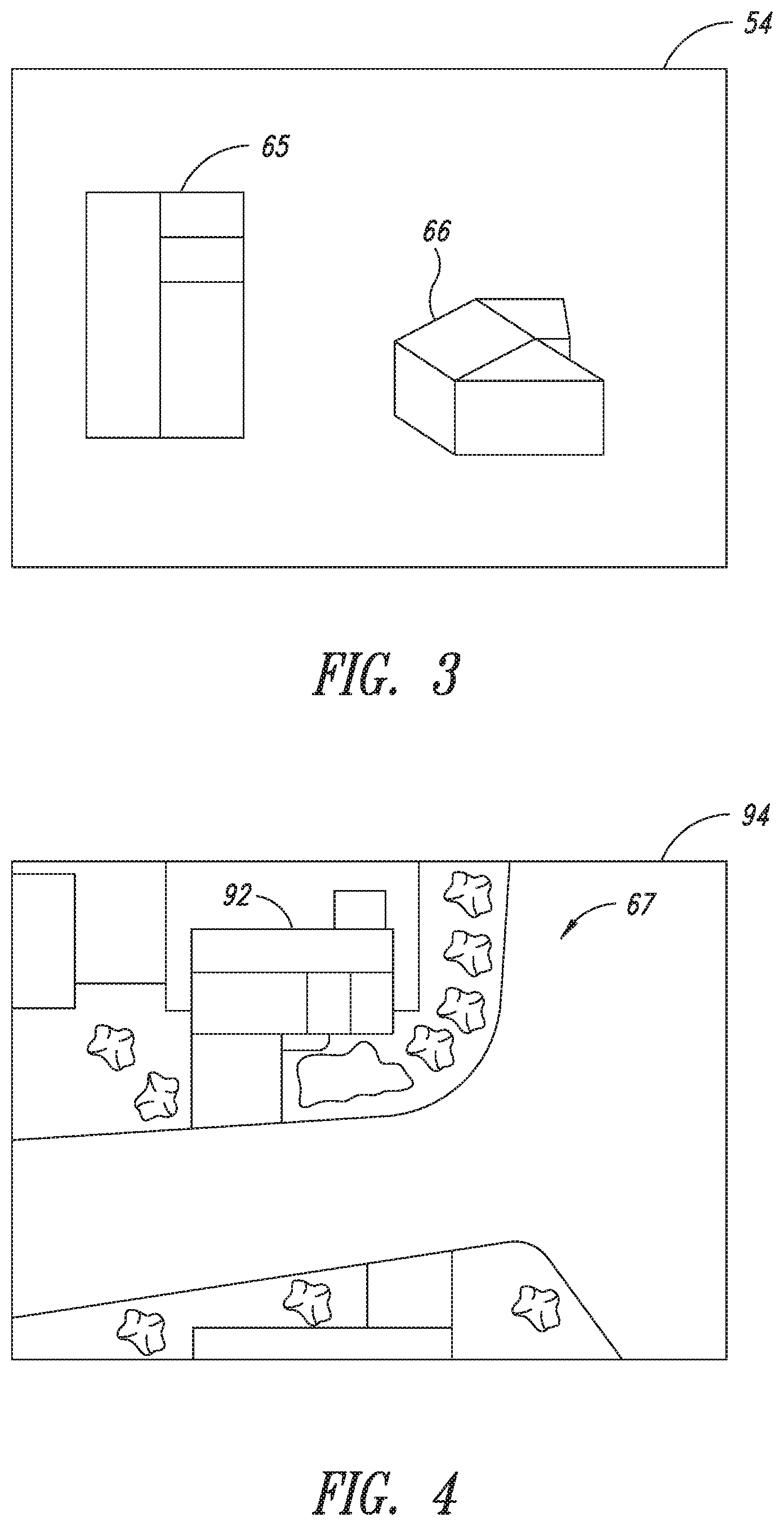
[0018] FIG. 3 is an illustration showing the top and perspective view of a house for a particular address.
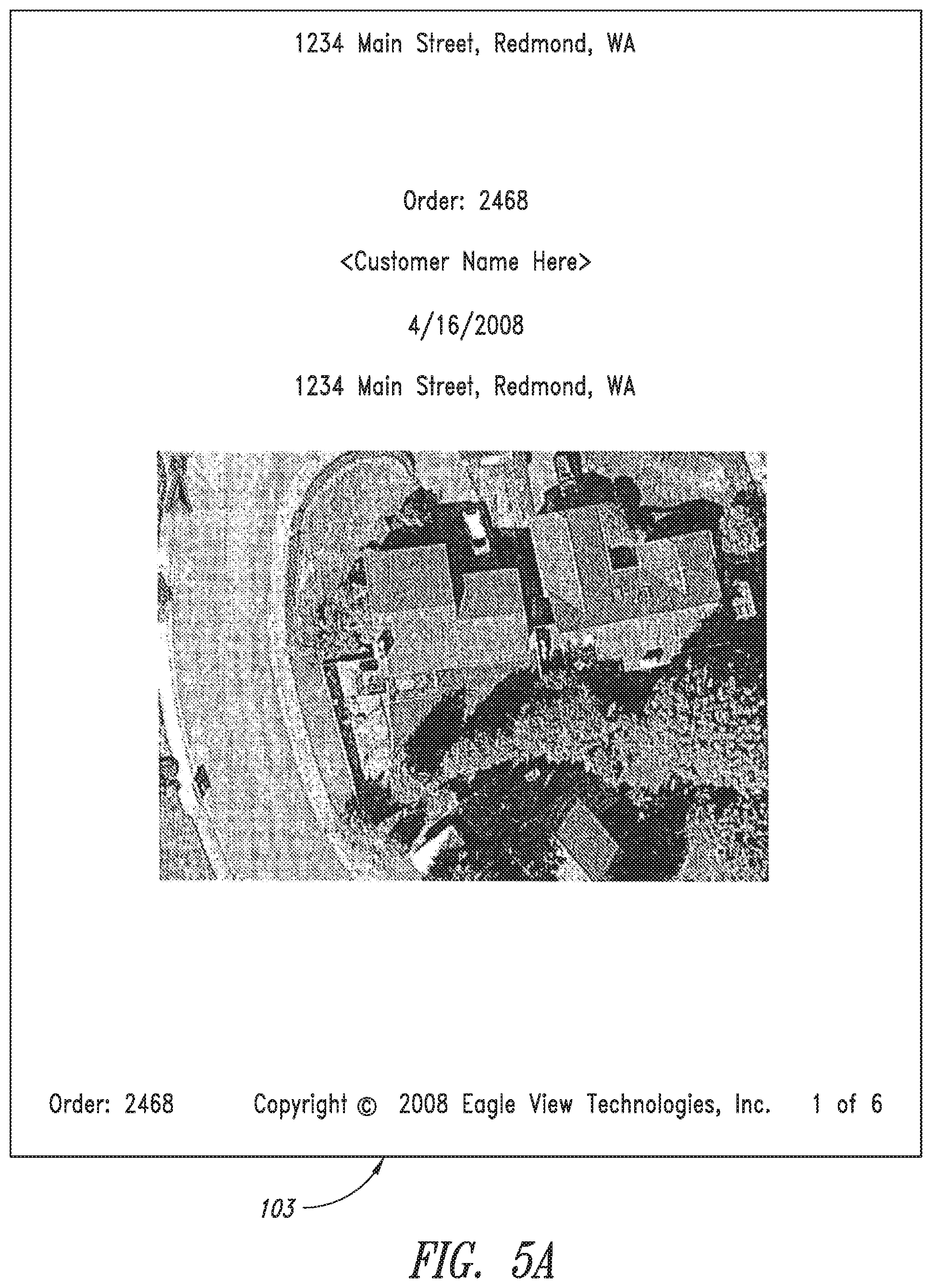
[0019] FIG. 4 is an aerial image of the home shown in FIG. 3 showing the areas and structures around the home.
[0020] FIGS. 5A-5F are consecutive pages from a preliminary or final report sent to a potential customer prepared by the roofing company.
DESCRIPTION OF THE PREFERRED EMBODIMENT(S)
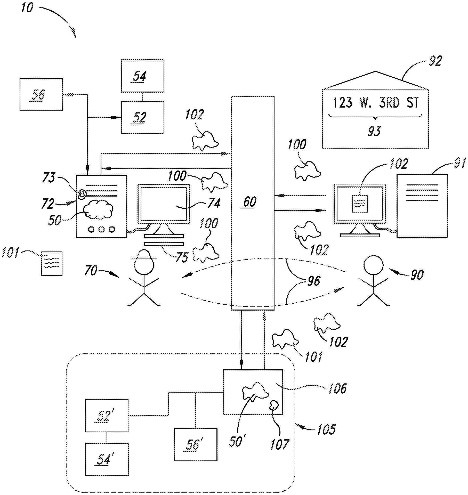
[0021] Referring to the accompanying Figures, there is described a system 10 and method that allows a roofing company 70 to provide a final estimate 102 to a potential customer 90 to install equipment or to repair or replace the roof on a building 92 using aerial images of the building 92. The system 10 includes an estimating software program 50 designed to receive an address for the building 92. The software program 50 is linked to an aerial image file database 52 that contains aerial images files 54 of various building 92 in a region. The aerial image files 54 may be taken any available means, such as an aircraft, balloon, a satellite, etc. As shown in FIG. 3, the image files 54 typically include at least one a top plan view 65 and a perspective view 66 of the building 92. The image files 54 may also include a wide angle image file 67 showing the building 92 and the surrounding areas 67 around the building 92. In one embodiment, an image analysis and calibration module 56 is linked to the software program 50 that enables the roof company 70 to closely estimate the dimensions and slopes of the roofs of the buildings 92 shown in the views 65, 66. By simply inputting the customer's address into the software program 50, the roof company 70 is able view the customer's roof from the aerial image files 54 using a remote computer 72, determine the dimensions and slopes of the roof sections that make up the roof, and prepare a preliminary report 101 which is then used to prepare a final estimate 102 that is then delivered to the potential customer 90.
[0022] FIG. 1 is an illustration showing the system 10 used by a potential customer 90 requesting a roof estimate from a roof company 70 that uses the system 10 described above. The potential customer 90 may be the building tenant, owner or insurance company. The roof company 70 uses a computer 72 which may connect to a wide area network 60. The customer 90 contacts the roof company 70 via his or her computer 91 and the wide area network 60 or by a telecommunication network 96, and requests a roof estimate for his building 92 located at a public address 93. (i.e. 23 W. 3.sup.rd St). The roof company 70 then processes the request 100 which leads to a final estimate 102 being delivered to the potential customer's computer 91 or via email, fax or postal service to the potential customer 90.
[0023] There are several different ways the system 10 can be setup. FIG. 1 shows a first embodiment of the system 10 where the roof company 70 operates a remote computer 72 with a display 74 and a keyboard 75 or similar input means. A roof estimating software program 50 is loaded into the working memory 73 of the remote computer 72. The software program 50 is able to retrieve aerial images of buildings from the database 52 containing aerial images files 54 of buildings located in the region served by the roof company 70. In the first embodiment shown in FIG. 1, the remote computer 72 is linked or connected to a database 52 containing aerial images files 54 of the buildings. The software program 50 includes a calibration module 56 that enables the roof company 70 to determine the angles and dimensions of various roof sections shown in the images files 54. After the angles and dimensions are determined, the combined square footage of the building 92 can be determined which is then used to create a preliminary report 101. The roof company 70 then reviews the wide angle image file 94 (see FIG. 4) to determine if the building 92 has special access and clean up factors that may impact the final estimate 102. Once the preliminary report 101 or the final estimate 102 is prepared by the roof company 70, one or both can be transmitted to the customer 90 via the wide area network 60, the telecommunication network 96, or by postal service.
[0024] Also shown in Fig.1 is an alternative setup of the system 10 wherein a preliminary report 101 is prepared by a separate roof estimating entity 105 which is then forwarded to the roof company 70 who then prepares the final estimate 102 and sends it to the customer 90. The entity 105 includes a computer 106 with a roof estimating software program 50' loaded into the working memory 107. Like the software program 50 loaded into the roof contractor's computer 72 in the previous embodiment the software program 50' is also able to retrieve aerial images of houses from a database 52' containing aerial images files 54' of houses located in the region served by the roof company 70. An optional calibration module 56' may be provided which enables the entity 105 to determine the angles and linear dimensions of various roof sections on the house 92.
[0025] When the system 10 is setup to include the estimating entity 105, the customer contacts the roofing company 70. The roof company 70 then contacts the estimating entity 105 and forwards the address of the building 92 thereto. The estimating entity 105 then prepares the preliminary report 101 that is transmitted to the roof company 70. The roof company 70 then prepares the final report 102 and sends it to the customer 90.
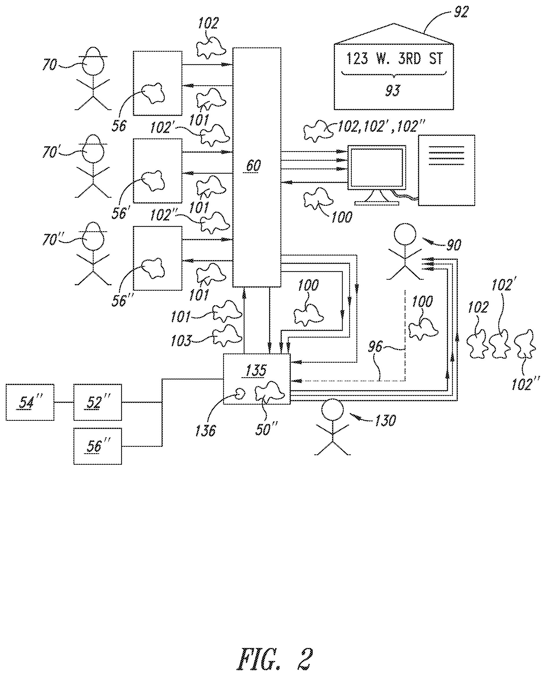
[0026] FIG. 2 shows a third embodiment of the system 10 where the customer 90 contacts a roof estimating entity 130 who receives a request 100 from the customer 90 via the wide area network 60 or telecommunication network 96. The roof estimating entity 130 prepares a preliminary report 101 which is then transmitted to various roof companies 70, 70', 70'' associated with the entity 130. Accompanying the preliminary report 101 may be the name and contact telephone number(s) or email address of the customer 90. Each roof company 70, 70', 70'' reviews the preliminary report 101 and any associated images sent therewith and then prepares a final estimate 102, 102', 102''. The final estimate 102, 102', 102''is then mailed, emailed or faxed to the customer 90 or back to the estimating entity 130. The estimating entity 130 then sends the final estimate 102, 102', 102'' to the customer 90. In this embodiment, the estimating entity 130 includes a computer 135 in which the roof estimating software program 50'' is loaded into its working memory 136 loaded and linked to the aerial image database 52''containing image files 54''. An optional calibration module 56'' may be loaded into the working memory 136 of the computer 135.
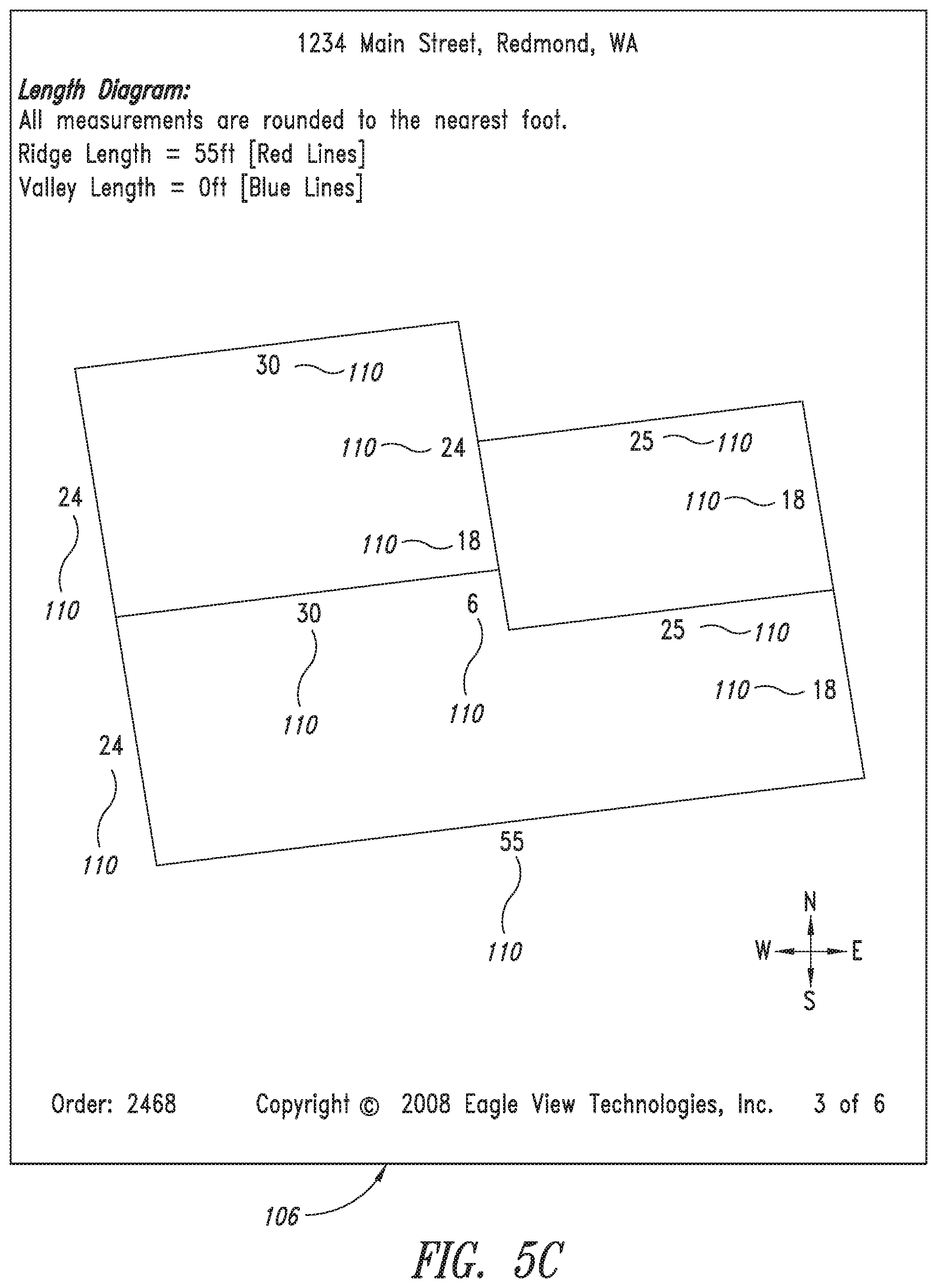
[0027] FIGS. 5A-5F are individual pages that make up a representative report. In FIG. 5A, a cover page 103 lists the address of the building and an overhead aerial image of the building. In FIG. 5B, a second page 104 of the report is shown that shows wide overhead perspective view of the building at the address with the surrounding areas more clearly shown. FIG. 5C is the third page 106 of the report which shows a line drawing of the building showing ridge and valley lines, dimensions 110 and a compass indicator. FIG. 5D is an illustration of the fourth page 107 of the report showing the pitch angle 111 of each roof section along with a compass indicator. FIG. 5E is an illustration of the fifth page 108 of the report showing the square footage 112 of each roof section along with the total square foot area value. FIG. 5F is an illustration of a sixth page 109 of the report showing an overall, aerial line drawing of the building where notes 113 or written comments may be written.
[0028] Using the above system, a detailed description of how the system is used is now provided.
[0029] First, a property of interest is identified by a potential customer of the service. The customer contacts the service with the location of the property. Typically, this will be a street address. The service then uses a geo-coding provider to translate the location information (such as a street address) into a set of coordinates that can be used to query an aerial or satellite image database. Typically, the geo-coding provider will be used to translate the customer supplied street address into a set of longitude-latitude coordinates.
[0030] Next, the longitude-latitude coordinates of the property are then used to query an aerial and/or satellite imagery database in order to retrieve one or more images of the property of interest. It is important to note that flat roofs only require a single image of the property. Roofs containing one or more pitched sections typically require two or more photographs in order to identify and measure all relevant sections and features of the roof.
[0031] Once the images of the roof section of the building are obtained, at least one of the images needs to be calibrated. During calibration, the distance in pixels between two points on the image is converted into a physical length. This calibration information is typically presented as a scale marker on the image itself, or as additional information supplied by the image database provider along with the requested image.
[0032] The image(s) and calibration information returned by the imagery database is entered or imported into the service's measurement software.
[0033] A set of reference points are identified in each of the images. The service's measurement software then uses these reference points and some proprietary algorithms to co-register the images and reconstruct the three dimensional geometry of the object identified by the reference points. There are a variety of photo-grammetric algorithms that can be utilized to perform this reconstruction. One such algorithm used by the service uses photographs taken from two or more view points to `triangulate` points of interest on the object in 3D space. This triangulation can be visualized as a process of projecting a line originating from the location of the photograph's observation point that passes through a particular reference point in the image. The intersection of these projected lines from the set of observation points to a particular reference point identifies the location of that point in 3D space. Repeating the process for all such reference points allows the software to build a 3D model of the structure.
[0034] The optimal choice of reconstruction algorithm depends on a number of factors such as the spatial relationships between the photographs, the number and locations of the reference points, and any assumptions that are made about the geometry and symmetry of the object being reconstructed. Several such algorithms are described in detail in textbooks, trade journals, and academic publications.
[0035] Once the reconstruction of the building is complete, the results are reviewed for completeness and correctness. If necessary, a user of the service's software will make corrections to the reconstructed model.
[0036] Information from the reconstructed model is used to generate a report containing information relevant to the customer. If the report is meant for delivery to a roofing company, the information in the report may include total square footage, square footage 112 and pitch 111 of each section of roof, linear measurements 110 of all roof segments, identification and measurement of ridges and valleys, and different elevation views rendered from the 3D model (top, side, front, etc.).
[0037] Using the above description, a method for estimating the size and the repair or replacement costs of a roof comprising the following steps:
[0038] a. selecting a roof estimation system that includes a computer with a roof estimation software program loaded into its working memory, said roof estimation software uses aerial image files of buildings in a selected region and a calibration module that allows the size, geometry, and orientation of a roof section to be determined from said aerial image files;
[0039] b. submitting a request for a measurement of a roof of a building at a known location;
[0040] c. submitting the location information of a building with a roof that needs a size determination, a repair estimate, or replacement estimate;
[0041] d. entering the location information of said building and obtaining aerial image files of one or more roof sections used on a roof; and,
[0042] e. using said calibration module to determine the size, geometry and pitch of each said roof section.
[0043] In the above method, the entity requesting the measurement is the building tenant, the building owner, or the insurance request.
[0044] In compliance with the statute, the invention described herein has been described in language more or less specific as to structural features. It should be understood however, that the invention is not limited to the specific features shown, since the means and construction shown, is comprised only of the preferred embodiments for putting the invention into effect. The invention is therefore claimed in any of its forms or modifications within the legitimate and valid scope of the amended claims, appropriately interpreted in accordance with the doctrine of equivalents.
* * * * *
D00000
D00001
D00002
D00003
D00004
D00005
D00006
D00007
D00008
D00009
XML
uspto.report is an independent third-party trademark research tool that is not affiliated, endorsed, or sponsored by the United States Patent and Trademark Office (USPTO) or any other governmental organization. The information provided by uspto.report is based on publicly available data at the time of writing and is intended for informational purposes only.
While we strive to provide accurate and up-to-date information, we do not guarantee the accuracy, completeness, reliability, or suitability of the information displayed on this site. The use of this site is at your own risk. Any reliance you place on such information is therefore strictly at your own risk.
All official trademark data, including owner information, should be verified by visiting the official USPTO website at www.uspto.gov. This site is not intended to replace professional legal advice and should not be used as a substitute for consulting with a legal professional who is knowledgeable about trademark law.