Method, System And Apparatus For Support Structure Depth Determination
Phan; Raymond ; et al.
U.S. patent application number 16/152986 was filed with the patent office on 2020-04-09 for method, system and apparatus for support structure depth determination. The applicant listed for this patent is Zebra Technologies Corporation. Invention is credited to Joseph Lam, Raymond Phan, Richard Jeffrey Rzeszutek, Yuanhao Yu.
| Application Number | 20200109939 16/152986 |
| Document ID | / |
| Family ID | 70051904 |
| Filed Date | 2020-04-09 |
| United States Patent Application | 20200109939 |
| Kind Code | A1 |
| Phan; Raymond ; et al. | April 9, 2020 |
METHOD, SYSTEM AND APPARATUS FOR SUPPORT STRUCTURE DEPTH DETERMINATION
Abstract
A method of determining a support structure depth of a support structure having a front and a back separated by the support structure depth includes: obtaining a point cloud of the support structure, and a mask indicating, for a plurality of portions of an image of the support structure captured from a capture pose, respective confidence levels that the portions depict the back of the support structure; selecting, from the point cloud, an initial set of points located within a field of view originating at the capture pose; selecting, from the initial set of points, an unoccluded subset of depth measurements, the depth measurements in the unoccluded subset corresponding to respective image coordinates; retrieving, from the mask, a confidence level for each of the depth measurements in the unoccluded subset; and based on the depth measurements in the unoccluded subset and the retrieved confidence levels, determining the support structure depth.
| Inventors: | Phan; Raymond; (Mississauga, CA) ; Yu; Yuanhao; (Mississauga, CA) ; Rzeszutek; Richard Jeffrey; (Toronto, CA) ; Lam; Joseph; (North York, CA) | ||||||||||
| Applicant: |
|
||||||||||
|---|---|---|---|---|---|---|---|---|---|---|---|
| Family ID: | 70051904 | ||||||||||
| Appl. No.: | 16/152986 | ||||||||||
| Filed: | October 5, 2018 |
| Current U.S. Class: | 1/1 |
| Current CPC Class: | G06T 7/00 20130101; G01B 11/22 20130101; G01B 11/24 20130101 |
| International Class: | G01B 11/22 20060101 G01B011/22 |
Claims
1. A method of determining a support structure depth of a support structure having a front and a back separated by the support structure depth, the method comprising: obtaining (i) a point cloud of the support structure, and (ii) a mask indicating, for a plurality of portions of an image of the support structure captured from a capture pose, respective confidence levels that the portions depict the back of the support structure; selecting, from the point cloud, an initial set of points located within a field of view originating at the capture pose; selecting, from the initial set of points, an unoccluded subset of depth measurements, the depth measurements in the unoccluded subset corresponding to respective image coordinates; retrieving, from the mask, a confidence level for each of the depth measurements in the unoccluded subset; and based on the depth measurements in the unoccluded subset and the retrieved confidence levels, determining the support structure depth.
2. The method of claim 1, further comprising: obtaining a further mask corresponding to a further image of the support structure captured from a further capture pose; selecting a further initial set of points; selecting a further unoccluded set of depth measurements; retrieving a further confidence level for each of the depth measurements in the further unoccluded subset.
3. The method of claim 2, further comprising: determining the support structure depth based on the depth measurements in the unoccluded subset, the depth measurements in the further unoccluded subset, the confidence levels and the further confidence levels.
4. The method of claim 1, wherein a capture pose defines a camera position and orientation within a common frame of reference.
5. The method of claim 1, wherein selecting the initial set of points comprises: generating a tree data structure containing, for each point in the point cloud, first and second dimensions orthogonal to the support structure depth; determining a field of view center in the first and second dimensions; and retrieving, from the tree data structure, the initial set of points within a predefined radius of the field of view center.
6. The method of claim 1, wherein selecting the unoccluded subset of depth measurements comprises: determining image coordinates corresponding to each of the initial set of points; identifying neighbor groups of the image coordinates; and for each neighbor group, selecting the image coordinate corresponding to the smallest depth measurement.
7. The method of claim 1, wherein determining the support structure depth comprises: obtaining a plane definition corresponding to the front of the support structure; transforming each depth measurement of the unoccluded subset of depth measurements to a depth relative to the plane definition; weighting each transformed depth measurement according to the retrieved confidence levels; and determining an average of the weighted depth measurements.
8. The method of claim 1, further comprising: prior to determining the support structure depth, discarding depth measurements for which the retrieved confidence levels are below a minimum confidence threshold.
9. The method of claim 1, further comprising: prior to determining the support structure depth, discarding depth measurements exceeding a maximum depth threshold.
10. A computing device for determining a support structure depth of a support structure having a front and a back separated by the support structure depth, the computing device comprising: a memory storing (i) a point cloud of the support structure, and (ii) a mask indicating, for a plurality of portions of an image of the support structure captured from a capture pose, respective confidence levels that the portions depict the back of the support structure; an imaging controller connected to the memory and configured to: select, from the point cloud, an initial set of points located within a field of view originating at the capture pose; select, from the initial set of points, an unoccluded subset of depth measurements, the depth measurements in the unoccluded subset corresponding to respective image coordinates; retrieve, from the mask, a confidence level for each of the depth measurements in the unoccluded subset; and based on the depth measurements in the unoccluded subset and the retrieved confidence levels, determine the support structure depth.
11. The computing device of claim 10, wherein the imaging controller is further configured to: obtain a further mask corresponding to a further image of the support structure captured from a further capture pose; select a further initial set of points; select a further unoccluded set of depth measurements; retrieve a further confidence level for each of the depth measurements in the further unoccluded subset.
12. The computing device of claim 11, wherein the imaging controller is further configured to: determine the support structure depth based on the depth measurements in the unoccluded subset, the depth measurements in the further unoccluded subset, the confidence levels and the further confidence levels.
13. The computing device of claim 10, wherein a capture pose defines a camera position and orientation within a common frame of reference.
14. The computing device of claim 10, wherein the imaging controller is further configured, to select the initial set of points, to: generate a tree data structure containing, for each point in the point cloud, first and second dimensions orthogonal to the support structure depth; determine a field of view center in the first and second dimensions; and retrieve, from the tree data structure, the initial set of points within a predefined radius of the field of view center.
15. The computing device of claim 10, wherein the imaging controller is further configured, to select the unoccluded subset of depth measurements, to: determine image coordinates corresponding to each of the initial set of points; identify neighbor groups of the image coordinates; and for each neighbor group, select the image coordinate corresponding to the smallest depth measurement.
16. The computing device of claim 10, wherein the imaging controller is further configured, to determine the support structure depth, to: obtain a plane definition corresponding to the front of the support structure; transform each depth measurement of the unoccluded subset of depth measurements to a depth relative to the plane definition; weight each transformed depth measurement according to the retrieved confidence levels; and determine an average of the weighted depth measurements.
17. The computing device of claim 10, wherein the imaging controller is further configured to: prior to determining the support structure depth, discard depth measurements for which the retrieved confidence levels are below a minimum confidence threshold.
18. The computing device of claim 10, wherein the imaging controller is further configured to: prior to determining the support structure depth, discard depth measurements exceeding a maximum depth threshold.
19. A computer-readable medium having stored thereon computer-executable instructions, the instructions comprising: obtaining (i) a point cloud of the support structure, and (ii) a mask indicating, for a plurality of portions of an image of the support structure captured from a capture pose, respective confidence levels that the portions depict the back of the support structure; selecting, from the point cloud, an initial set of points located within a field of view originating at the capture pose; selecting, from the initial set of points, an unoccluded subset of depth measurements, the depth measurements in the unoccluded subset corresponding to respective image coordinates; retrieving, from the mask, a confidence level for each of the depth measurements in the unoccluded subset; and based on the depth measurements in the unoccluded subset and the retrieved confidence levels, determining the support structure depth.
20. The computer-readable medium of claim 19, the instructions further comprising: determining the support structure depth based on the depth measurements in the unoccluded subset, the depth measurements in the further unoccluded subset, the confidence levels and the further confidence levels.
Description
BACKGROUND
[0001] Environments in which inventories of objects are managed, such as products for purchase in a retail environment, may be complex and fluid. For example, a given environment may contain a wide variety of objects with different attributes (size, shape, price and the like). Further, the placement and quantity of the objects in the environment may change frequently. Still further, imaging conditions such as lighting may be variable both over time and at different locations in the environment. These factors may reduce the accuracy with which information concerning the objects may be collected within the environment.
BRIEF DESCRIPTION OF THE SEVERAL VIEWS OF THE DRAWINGS
[0002] The accompanying figures, where like reference numerals refer to identical or functionally similar elements throughout the separate views, together with the detailed description below, are incorporated in and form part of the specification, and serve to further illustrate embodiments of concepts that include the claimed invention, and explain various principles and advantages of those embodiments.
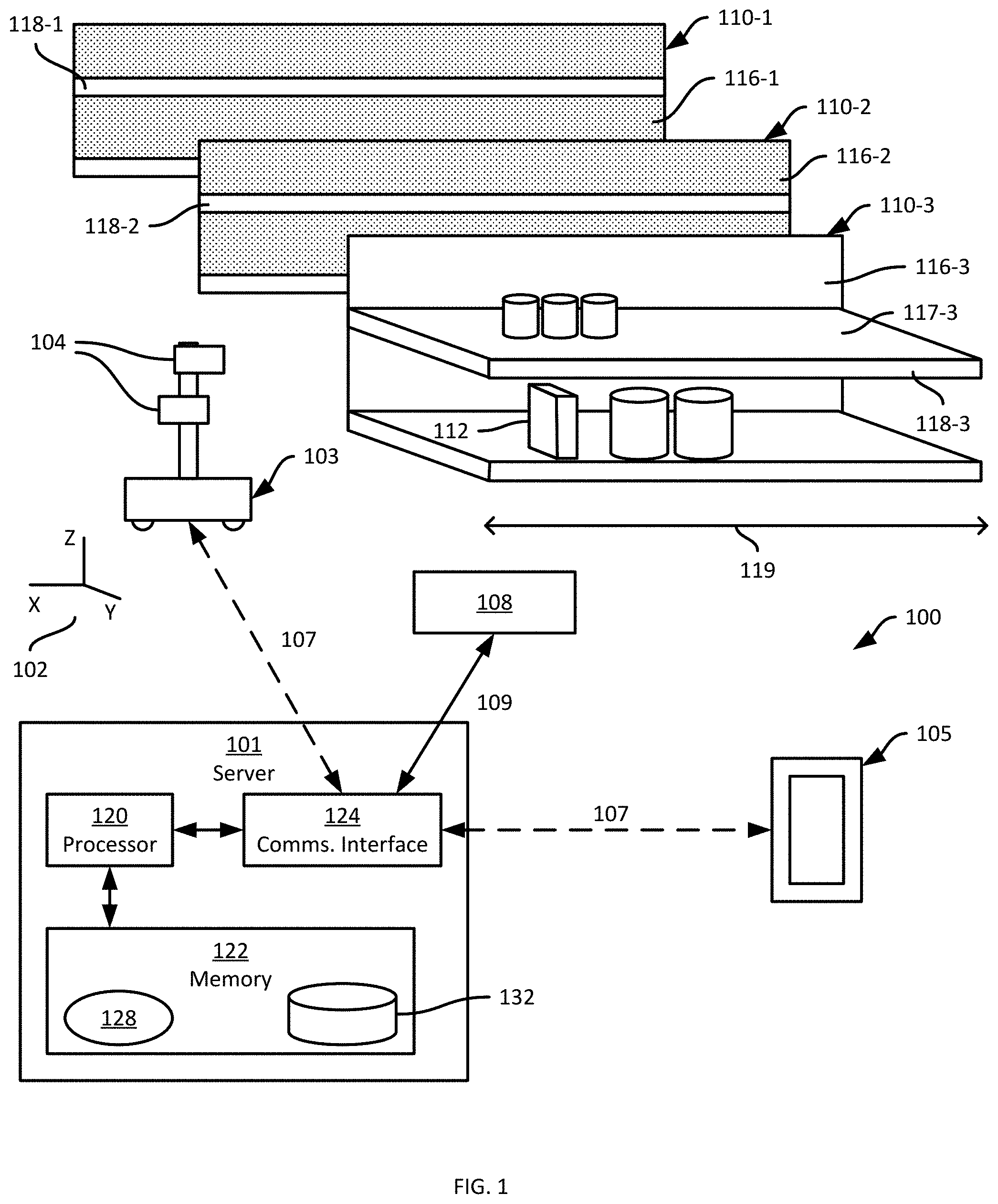
[0003] FIG. 1 is a schematic of a mobile automation system.
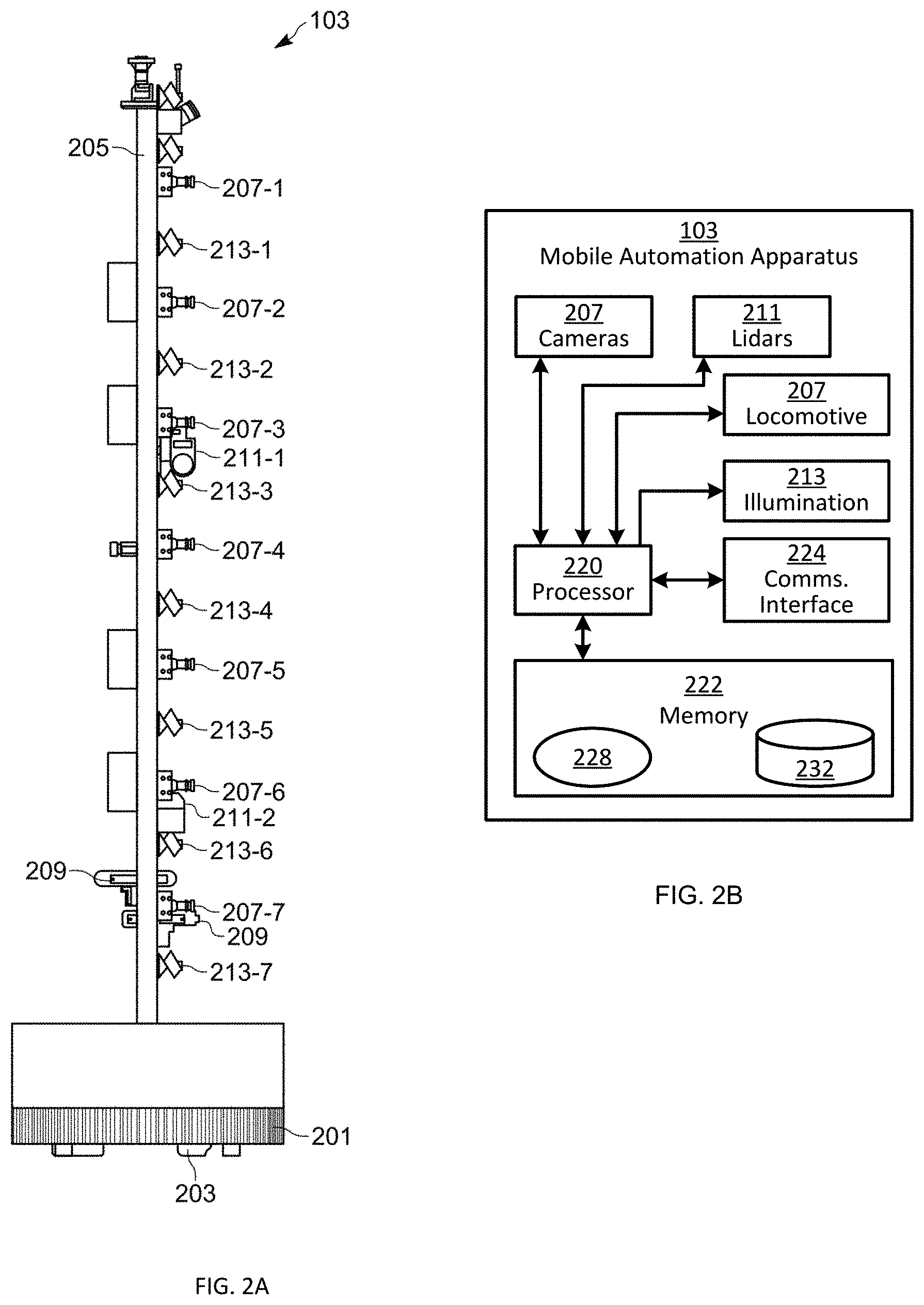
[0004] FIG. 2A depicts a mobile automation apparatus in the system of FIG. 1.
[0005] FIG. 2B is a block diagram of certain internal hardware components of the mobile automation apparatus in the system of FIG. 1.
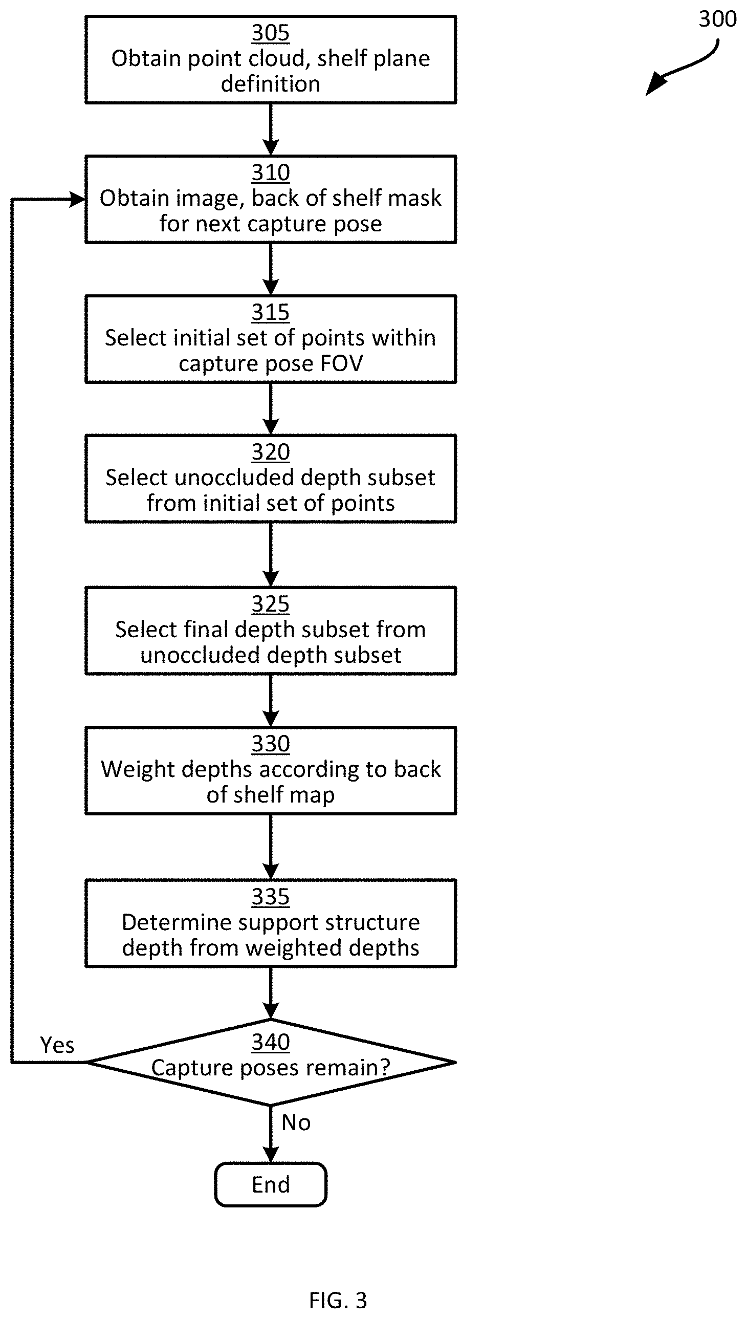
[0006] FIG. 3 is a flowchart of a method for determining a support structure depth.
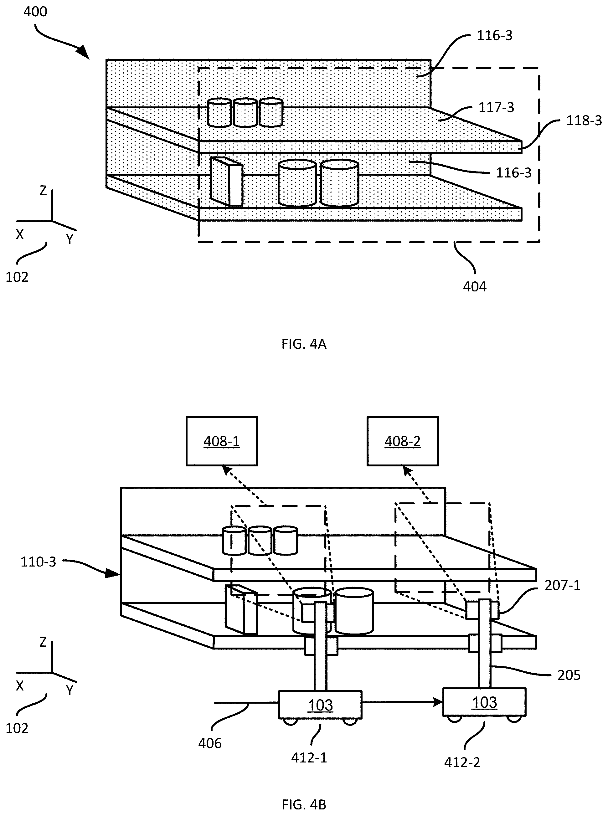
[0007] FIG. 4A is a diagram of a point cloud and shelf plane obtained at block 305 of the method of FIG. 3.
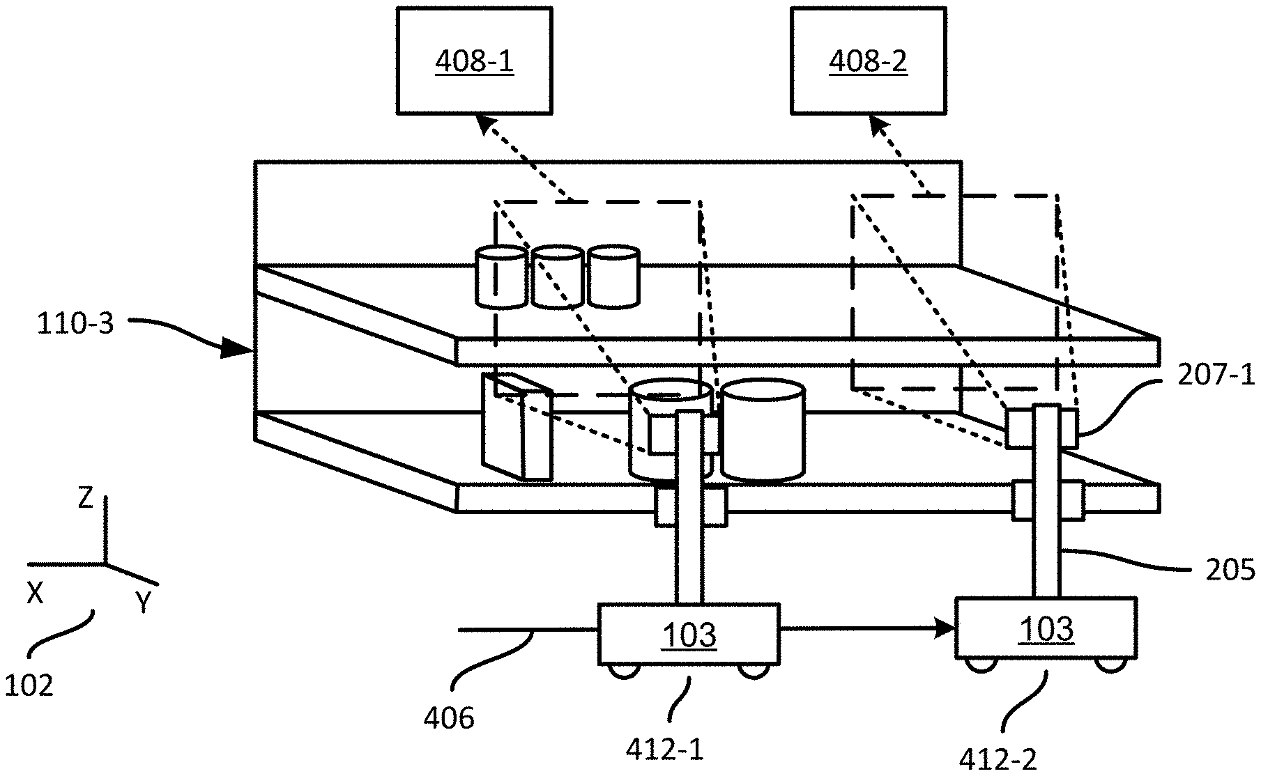
[0008] FIG. 4B is a diagram of example images captured by the apparatus of the system of FIG. 1, and obtained at block 310 of the method of FIG. 3.
[0009] FIG. 5A is a diagram illustrating one of the images of FIG. 4B in greater detail.
[0010] FIG. 5B is a diagram illustrating an example back of shelf mask corresponding to the image of FIG. 5A.
[0011] FIG. 6A is a flowchart of a method for performing block 315 of the method of FIG. 3.
[0012] FIG. 6B is a diagram illustrating the performance of the method of FIG. 6A in connection with the point cloud of FIG. 4A.
[0013] FIG. 7A is a flowchart of a method of performing block 320 of the method of FIG. 3.
[0014] FIG. 7B is a diagram illustrating the performance of the method of FIG. 7A in connection with the image of FIG. 5A.
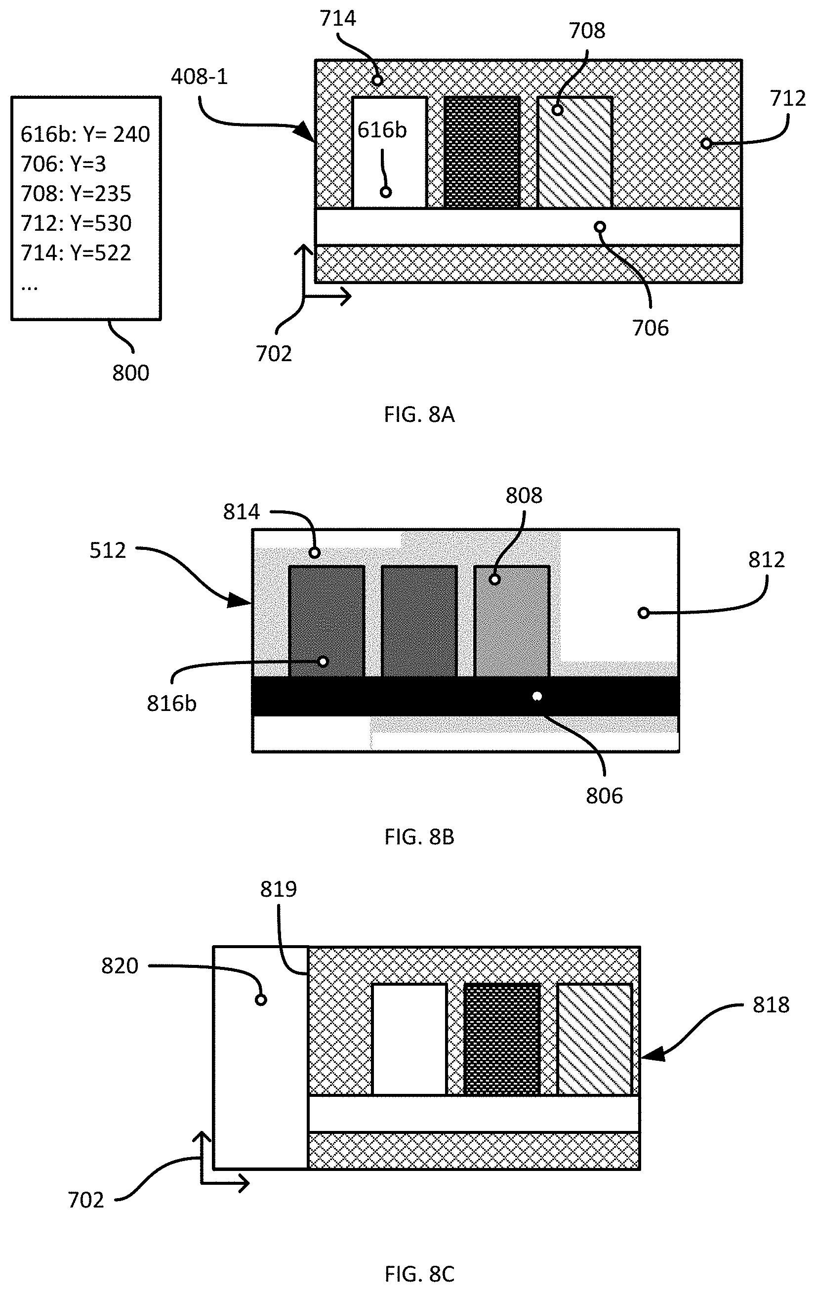
[0015] FIGS. 8A and 8B are diagrams illustrating an example performance of block 325 of the method of FIG. 3.
[0016] FIG. 8C is a diagram illustrating a further example performance of block 325 of the method of FIG. 3.
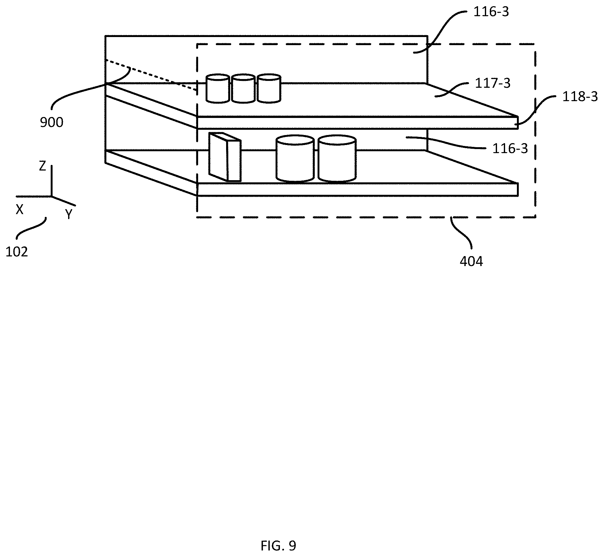
[0017] FIG. 9 is a diagram illustrating a support structure depth determined via performance of the method of FIG. 3.
[0018] Skilled artisans will appreciate that elements in the figures are illustrated for simplicity and clarity and have not necessarily been drawn to scale. For example, the dimensions of some of the elements in the figures may be exaggerated relative to other elements to help to improve understanding of embodiments of the present invention.
[0019] The apparatus and method components have been represented where appropriate by conventional symbols in the drawings, showing only those specific details that are pertinent to understanding the embodiments of the present invention so as not to obscure the disclosure with details that will be readily apparent to those of ordinary skill in the art having the benefit of the description herein.
DETAILED DESCRIPTION
[0020] Examples disclosed herein are directed to a method of determining a support structure depth of a support structure having a front and a back separated by the support structure depth, the method comprising: obtaining (i) a point cloud of the support structure, and (ii) a mask indicating, for a plurality of portions of an image of the support structure captured from a capture pose, respective confidence levels that the portions depict the back of the support structure; selecting, from the point cloud, an initial set of points located within a field of view originating at the capture pose; selecting, from the initial set of points, an unoccluded subset of depth measurements, the depth measurements in the unoccluded subset corresponding to respective image coordinates; retrieving, from the mask, a confidence level for each of the depth measurements in the unoccluded subset; and based on the depth measurements in the unoccluded subset and the retrieved confidence levels, determining the support structure depth.
[0021] Additional examples disclosed herein are directed to a computing device for determining a support structure depth of a support structure having a front and a back separated by the support structure depth, the computing device comprising: a memory storing (i) a point cloud of the support structure, and (ii) a mask indicating, for a plurality of portions of an image of the support structure captured from a capture pose, respective confidence levels that the portions depict the back of the support structure; an imaging controller connected to the memory and configured to: select, from the point cloud, an initial set of points located within a field of view originating at the capture pose; select, from the initial set of points, an unoccluded subset of depth measurements, the depth measurements in the unoccluded subset corresponding to respective image coordinates; retrieve, from the mask, a confidence level for each of the depth measurements in the unoccluded subset; and based on the depth measurements in the unoccluded subset and the retrieved confidence levels, determine the support structure depth.
[0022] Further examples disclosed herein are directed to a computer-readable medium storing computer-readable instructions executable by a processor of a server, wherein execution of the computer-readable instructions causes the server to: obtain (i) a point cloud of the support structure, and (ii) a mask indicating, for a plurality of portions of an image of the support structure captured from a capture pose, respective confidence levels that the portions depict the back of the support structure; select, from the point cloud, an initial set of points located within a field of view originating at the capture pose; select, from the initial set of points, an unoccluded subset of depth measurements, the depth measurements in the unoccluded subset corresponding to respective image coordinates; retrieve, from the mask, a confidence level for each of the depth measurements in the unoccluded subset; and based on the depth measurements in the unoccluded subset and the retrieved confidence levels, determine the support structure depth.
[0023] FIG. 1 depicts a mobile automation system 100 in accordance with the teachings of this disclosure. The system 100 is illustrated as being deployed in a retail environment, but in other embodiments can be deployed in a variety of other environments, including warehouses, hospitals, and the like. The system 100 includes a server 101 in communication with at least one mobile automation apparatus 103 (also referred to herein simply as the apparatus 103) and at least one client computing device 105 via communication links 107, illustrated in the present example as including wireless links. In the present example, the links 107 are provided by a wireless local area network (WLAN) deployed within the retail environment by one or more access points (not shown). In other examples, the server 101, the client device 105, or both, are located outside the retail environment, and the links 107 therefore include wide-area networks such as the Internet, mobile networks, and the like. The system 100 also includes a dock 108 for the apparatus 103 in the present example. The dock 108 is in communication with the server 101 via a link 109 that in the present example is a wired link. In other examples, however, the link 109 is a wireless link.
[0024] The client computing device 105 is illustrated in FIG. 1 as a mobile computing device, such as a tablet, smart phone or the like. In other examples, the client device 105 is implemented as another type of computing device, such as a desktop computer, a laptop computer, another server, a kiosk, a monitor, and the like. The system 100 can include a plurality of client devices 105 in communication with the server 101 via respective links 107.
[0025] The system 100 is deployed, in the illustrated example, in a retail environment including a plurality of support structures such as shelf modules 110-1, 110-2, 110-3 and so on (collectively referred to as shelves 110, and generically referred to as a shelf 110--this nomenclature is also employed for other elements discussed herein). In other examples, additional types of support structures may also be present, such as pegboards. Each shelf module 110 supports a plurality of products 112. Each shelf module 110 includes a shelf back 116-1, 116-2, 116-3 and a support surface (e.g. support surface 117-3 as illustrated in FIG. 1) extending from the shelf back 116 to a shelf edge 118-1, 118-2, 118-3.
[0026] The shelf modules 110 are typically arranged in a plurality of aisles, each of which includes a plurality of modules 110 aligned end-to-end. In such arrangements, the shelf edges 118 face into the aisles, through which customers in the retail environment as well as the apparatus 103 may travel. As will be apparent from FIG. 1, the term "shelf edge" 118 as employed herein, which may also be referred to as the edge of a support surface (e.g., the support surfaces 117) refers to a surface bounded by adjacent surfaces having different angles of inclination. In the example illustrated in FIG. 1, the shelf edge 118-3 is at an angle of about ninety degrees relative to each of the support surface 117-3 and the underside (not shown) of the support surface 117-3. In other examples, the angles between the shelf edge 118-3 and the adjacent surfaces, such as the support surface 117-3, is more or less than ninety degrees. The shelf edges 118 define a front of the shelves 110, separated from the shelf backs 116 by a shelf depth. A common frame of reference 102 is illustrated in FIG. 1. In the present example, the shelf depth is defined in the Y dimension of the frame of reference 102, while the shelf backs 116 and shelf edges 118 are shown as being parallel to the XZ plane.
[0027] The apparatus 103 is deployed within the retail environment, and communicates with the server 101 (e.g. via the link 107) to navigate, autonomously or partially autonomously, along a length 119 (illustrated in FIG. 1 as being parallel to the X axis of the frame of reference 102) of at least a portion of the shelves 110. The apparatus 103, autonomously or in conjunction with the server 101, is configured to continuously determine its location within the environment, for example with respect to a map of the environment. The apparatus 103 may also be configured to update the map (e.g. via a simultaneous mapping and localization, or SLAM, process).
[0028] The apparatus 103 is equipped with a plurality of navigation and data capture sensors 104, such as image sensors (e.g. one or more digital cameras) and depth sensors (e.g. one or more Light Detection and Ranging (LIDAR) sensors, one or more depth cameras employing structured light patterns, such as infrared light, or the like). The apparatus 103 can be configured to employ the sensors 104 to both navigate among the shelves 110 (e.g. according to the paths mentioned above) and to capture shelf data, such as point cloud and image data, during such navigation.
[0029] The server 101 includes a special purpose imaging controller, such as a processor 120, specifically designed to control and/or assist the mobile automation apparatus 103 to navigate the environment and to capture data. The processor 120 can be further configured to obtain the captured data via a communications interface 124 for storage in a repository 132 and subsequent processing (e.g. to detect objects such as shelved products in the captured data, and detect status information corresponding to the objects). The server 101 may also be configured to transmit status notifications (e.g. notifications indicating that products are out-of-stock, low stock or misplaced) to the client device 105 responsive to the determination of product status data. The client device 105 includes one or more controllers (e.g. central processing units (CPUs) and/or field-programmable gate arrays (FPGAs) and the like) configured to process (e.g. to display) notifications received from the server 101.
[0030] The processor 120 is interconnected with a non-transitory computer readable storage medium, such as the above-mentioned memory 122, having stored thereon computer readable instructions for performing various functionality, including control of the apparatus 103 to capture shelf data, post-processing of the shelf data, and generating and providing certain navigational data to the apparatus 103, such as target locations at which to capture shelf data. The memory 122 includes a combination of volatile (e.g. Random Access Memory or RAM) and non-volatile memory (e.g. read only memory or ROM, Electrically Erasable Programmable Read Only Memory or EEPROM, flash memory). The processor 120 and the memory 122 each comprise one or more integrated circuits. In some embodiments, the processor 120 is implemented as one or more central processing units (CPUs) and/or graphics processing units (GPUs).
[0031] The server 101 also includes the above-mentioned communications interface 124 interconnected with the processor 120. The communications interface 124 includes suitable hardware (e.g. transmitters, receivers, network interface controllers and the like) allowing the server 101 to communicate with other computing devices--particularly the apparatus 103, the client device 105 and the dock 108--via the links 107 and 109. The links 107 and 109 may be direct links, or links that traverse one or more networks, including both local and wide-area networks. The specific components of the communications interface 124 are selected based on the type of network or other links that the server 101 is required to communicate over. In the present example, as noted earlier, a wireless local-area network is implemented within the retail environment via the deployment of one or more wireless access points. The links 107 therefore include either or both wireless links between the apparatus 103 and the mobile device 105 and the above-mentioned access points, and a wired link (e.g. an Ethernet-based link) between the server 101 and the access point.
[0032] The memory 122 stores a plurality of applications, each including a plurality of computer readable instructions executable by the processor 120. The execution of the above-mentioned instructions by the processor 120 configures the server 101 to perform various actions discussed herein. The applications stored in the memory 122 include a control application 128, which may also be implemented as a suite of logically distinct applications. In general, via execution of the application 128 or subcomponents thereof and in conjunction with the other components of the server 101, the processor 120 is configured to implement various functionality related to controlling the apparatus 103 to navigate among the shelves 110 and capture data, as well as to obtain the captured data and perform various post-processing operations on the captured data. In the present example, as discussed below in greater detail, execution of the application 128 configures the server 101 to determine a shelf depth for one or more of the shelves 110, based on captured data (e.g. obtained from the apparatus 103) including point cloud and image data representing the shelves 110.
[0033] The processor 120, as configured via the execution of the control application 128, is also referred to herein as the controller 120. As will now be apparent, some or all of the functionality implemented by the controller 120 described below may also be performed by preconfigured special purpose hardware controllers (e.g. one or more logic circuit arrangements specifically configured to optimize the speed of image processing, for example via FPGAs and/or Application-Specific Integrated Circuits (ASICs) configured for this purpose) rather than by execution of the control application 128 by the processor 120.
[0034] Turning now to FIGS. 2A and 2B, the mobile automation apparatus 103 is shown in greater detail. The apparatus 103 includes a chassis 201 containing a locomotive mechanism 203 (e.g. one or more electrical motors driving wheels, tracks or the like). The apparatus 103 further includes a sensor mast 205 supported on the chassis 201 and, in the present example, extending upwards (e.g., substantially vertically) from the chassis 201. The mast 205 supports the sensors 104 mentioned earlier. In particular, the sensors 104 include at least one imaging sensor 207, such as a digital camera, as well as at least one depth sensor 209, such as a 3D digital camera. The apparatus 103 also includes additional depth sensors, such as LIDAR sensors 211. In other examples, the apparatus 103 includes additional sensors, such as one or more RFID readers, temperature sensors, and the like.
[0035] In the present example, the mast 205 supports seven digital cameras 207-1 through 207-7, and two LIDAR sensors 211-1 and 211-2. The mast 205 also supports a plurality of illumination assemblies 213, configured to illuminate the fields of view of the respective cameras 207. That is, the illumination assembly 213-1 illuminates the field of view of the camera 207-1, and so on. The sensors 207 and 211 are oriented on the mast 205 such that the fields of view of each sensor face a shelf 110 along the length 119 of which the apparatus 103 is travelling. The apparatus 103 is configured to track a location of the apparatus 103 (e.g. a location of the center of the chassis 201) in the common frame of reference 102 previously established in the retail facility, permitting data captured by the mobile automation apparatus 103 to be registered to the common frame of reference.
[0036] The mobile automation apparatus 103 includes a special-purpose controller, such as a processor 220, as shown in FIG. 2B, interconnected with a non-transitory computer readable storage medium, such as a memory 222. The memory 222 includes a combination of volatile (e.g. Random Access Memory or RAM) and non-volatile memory (e.g. read only memory or ROM, Electrically Erasable Programmable Read Only Memory or EEPROM, flash memory). The processor 220 and the memory 222 each comprise one or more integrated circuits. The memory 222 stores computer readable instructions for execution by the processor 220. In particular, the memory 222 stores a control application 228 which, when executed by the processor 220, configures the processor 220 to perform various functions related to the navigation of the apparatus 103 and capture of data for subsequent processing, e.g. by the server 101. In some embodiments, such subsequent processing can be performed by the apparatus 103 itself via execution of the application 228. The application 228 may also be implemented as a suite of distinct applications in other examples.
[0037] The processor 220, when so configured by the execution of the application 228, may also be referred to as an imaging controller 220. Those skilled in the art will appreciate that the functionality implemented by the processor 220 via the execution of the application 228 may also be implemented by one or more specially designed hardware and firmware components, including logic circuit configurations optimized for image and/or depth sensor data processing, such as via specifically configured FPGAs, ASICs and the like in other embodiments.
[0038] The memory 222 may also store a repository 232 containing, for example, one or more maps representing the environment in which the apparatus 103 operates, for use during the execution of the application 228. The apparatus 103 may communicate with the server 101, for example to receive instructions to navigate to specified locations and initiate data capture operations, via a communications interface 224 over the link 107 shown in FIG. 1. The communications interface 224 also enables the apparatus 103 to communicate with the server 101 via the dock 108 and the link 109.
[0039] As will be apparent in the discussion below, other examples, some or all of the processing performed by the server 101 may be performed by the apparatus 103, and some or all of the processing performed by the apparatus 103 may be performed by the server 101. That is, although in the illustrated example the application 128 resides in the server 101, in other embodiments some or all of the actions described below to determine the shelf depth of the shelves 110 from captured data may be performed by the processor 220 of the apparatus 103, either in conjunction with or independently from the processor 120 of the server 101. As those of skill in the art will realize, distribution of such computations between the server 101 and the mobile automation apparatus 103 may depend upon respective processing speeds of the processors 120 and 220, the quality and bandwidth of the link 107, as well as criticality level of the underlying instruction(s).
[0040] The functionality of the application 128 will now be described in greater detail. In particular, the support structure depth determination mentioned above will be described as performed by the server 101. Turning to FIG. 3, a method 300 of determining support structure depth is shown. The method 300 will be described in conjunction with its performance by the server 101, with reference to the components illustrated in FIG. 1.
[0041] At block 305, the server 101 is configured to obtain a point cloud of the support structure, as well as a plane definition corresponding to the front of the support structure. In the present example, in which the support structures are shelves such as the shelves 110 shown in FIG. 1, the point cloud obtained at block 305 therefore represents at least a portion of a shelf module 110 (and may represent a plurality of shelf modules 110), and the plane definition corresponds to a shelf plane that corresponds to the front of the shelf modules 110. In other words, the plane definition defines a plane that contains the shelf edges 118.
[0042] The point cloud and plane definition obtained at block 305 can be retrieved from the repository 132. For example, the server 101 may have previously received captured data from the apparatus 103 including a plurality of lidar scans of the shelf modules 110, and generated a point cloud from the lidar scans. Each point in the point cloud represents a point on a surface of the shelves 110, products 112, and the like (e.g. a point that the scan line of a lidar sensor 211 impacted), and is defined by a set of coordinates (X, Y and Z) in the frame of reference 102. The plane definition may also be previously generated by the server 101 and stored in the repository 132, for example from the above-mentioned point cloud. For example, the server 101 can be configured to process the point cloud, the raw lidar data, image data captured by the cameras 207, or a combination thereof, to identify shelf edges 118 according to predefined characteristics of the shelf edges 118. Examples of such characteristics include that the shelf edges 118 are likely to be substantially planar, and are also likely to be closer to the apparatus 103 as the apparatus 103 travels the length 119 of a shelf module 110) than other objects (such as the shelf backs 116 and products 112). The plane definition can be obtained in a variety of suitable formats, such as a suitable set of parameters defining the plane. An example of such parameters includes a normal vector (i.e. a vector defined according to the frame of reference 102 that is perpendicular to the plane) and a depth (indicating the distance along the normal vector from the origin of the frame of reference 102 to the plane).
[0043] Referring to FIG. 4A, a point cloud 400 is illustrated, depicting the shelf module 110-3. The shelf back 116-3, as well as the shelf 117-3 and shelf edge 118-3 are therefore shown in the point cloud 400. Also shown in FIG. 4A is a plane definition 404 corresponding to the front of the shelf module 110-3 (that is, the plane definition 404 contains the shelf edges 118-3). The point cloud 400 and the plane definition 404 need not be obtained in the graphical form shown in FIG. 4A. As will be apparent to those skilled in the art, the point cloud may be obtained as a list of coordinates, and the plane definition 404 may be obtained as the above-mentioned parameters.
[0044] Returning to FIG. 3, at block 310 the server 101 is configured to obtain at least one image of the support structure, as captured (e.g. by the apparatus 103) from a capture pose. The capture pose is a position and orientation of capture device such as a camera 207, within the frame of reference. The apparatus 103, as noted above, is configured to traverse one or more shelf modules 110 and capture images of the shelf modules 110. As will now be apparent, each image capture occurs at a certain position and orientation of the apparatus 103. Further, the apparatus 103 includes a plurality of cameras 207, as shown in FIG. 2A, each with a predefined physical position and orientation on the apparatus 103. Thus, at each pose (i.e. position and orientation) of the apparatus 103, a plurality of images may be captured, one for each camera 207. Each image thus corresponds to a specific capture pose, meaning the physical position of the camera 207 according to the frame of reference 102.
[0045] FIG. 4B illustrates the capture of two example images 408-1, 408-2 by the apparatus 103 as the apparatus 103 traverses the shelf module 110-3 in a travel direction 406. In particular, at a first apparatus pose 412-1, the apparatus 103 controls the camera 207-1 to capture the first image 408-1. The position and orientation of the camera 207-1 at the time of capture of the first image 408-1 thus corresponds to a first capture pose. Later during the traverse of the shelf module 110-3, at a second apparatus pose 412-2, the apparatus 103 controls the camera 207-1 to capture the second image 408-2. As will now be apparent, the second image 408-2 corresponds to a second capture pose defined by the apparatus pose 412-2 and the physical orientation of the camera 207-1 relative to the apparatus 103. Each of the other cameras 207 may also be controlled to capture images at each apparatus pose 412. The images captured by those other cameras 207 correspond to yet more capture poses.
[0046] Returning to FIG. 3, at block 310 the server 101 is also configured to obtain, for example by retrieval from the repository 132, a mask also referred to as a back of shelf (BoS) mask or a BoS map. The mask corresponds to the at least one image mentioned above. That is, for each image obtained at block 310, one corresponding mask can also be obtained. The mask is derived from the corresponding image, and indicates, for each of a plurality of portions of the image, a confidence level that the portion depicts the shelf back 116. The portions can be individual pixels, if the mask has the same resolution as the image. In other examples, the mask has a lower resolution than the image, and each confidence level in the mask therefore corresponds to a portion of the image that contains multiple pixels.
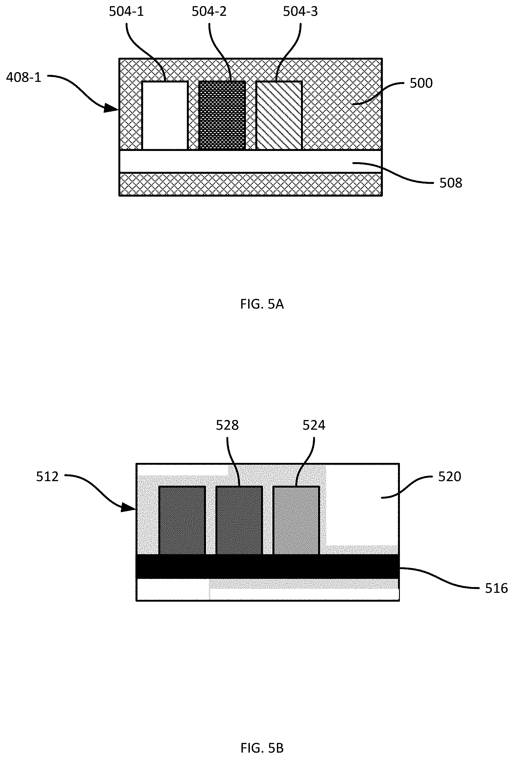
[0047] FIG. 5A illustrates the image 408-1 shown in FIG. 4A. As shown in FIG. 5A, a portion 500 of the image 408-1 depicts the shelf back 116-3. Portions 504-1, 504-2 and 504-3, meanwhile, depict products 112, and a portion 508 depicts the shelf edge 118-3. FIG. 5B illustrates a mask 512 derived from the image 408-1. Various mechanisms can be employed for generating the mask. For example, the image 408-1 can be decomposed into patches of a predefined size (e.g. 5.times.5 pixels), and each patch can be classified by a suitable classification operation to generate a confidence level, indicating a degree to which the patch matches a reference image of shelf back 116-3. The mask 512 can then be constructed by combining the confidence levels assigned to each patch.
[0048] In FIG. 5B, the confidence levels of the mask 512 are represented in grayscale. Darker regions of the mask 512 indicate lower confidence that the corresponding portion of the image 408-1 depicts the shelf back 116-3 (or, in other words, higher confidence that the corresponding portion of the image 408-1 does not depict the shelf back 116-3) and lighter regions of the mask 512 indicate higher confidence that the corresponding portion of the image 408-1 depicts the shelf back 116-3. For example, a region 516 indicates a confidence level of zero that the portion 508 of the image 408-1 depicts the shelf back 116-3. Another region 520 of the mask 512 indicates a maximum confidence level (e.g. 100%) that the corresponding portion of the image 408-1 depicts the shelf back 116-3. Other regions of the mask 512 indicate intermediate confidence levels. For example, a region 524 indicates a confidence level of about 50%, because the pattern shown on the product 112 depicted in the portion 504-3 of the image 408-1 resembles the shelf back 116-3. The region 528 of the mask 512, meanwhile, indicates a confidence level of about 30%.
[0049] Various other mechanisms for storing the confidence levels of the mask 512 are contemplated, beyond the grayscale image shown in FIG. 5B. For example, the confidence levels may be stored in a list, with associated sets of image coordinates indicating which portion of the image 408-1 corresponds to each confidence level.
[0050] Having obtained the point cloud, plane definition, image(s) and mask(s) at blocks 305 and 310, the server 101 is then configured to identify a subset of the points in the point cloud for which corresponding confidence levels exist in the mask 512. That is, the server 101 identifies points in the point cloud that were visible to the camera 207 at the time that the image was captured. The server 101 is then configured to use the depths of such points relative to the shelf plane in conjunction with the corresponding confidence levels from the mask 512, to determine a depth of the shelf back 116 relative to the shelf plane. The above functionality will be discussed below in greater detail.
[0051] Returning to FIG. 3, at block 315 the server 101 is configured to select an initial set of points from the point cloud, that fall within a field of view established by the capture pose mentioned above. Referring briefly to FIG. 4B, the field of view of the camera 207-2 is shown in dashed lines at each capture pose 412. The capture pose is defined according to the frame of reference 102, and according to predefined operational parameters (e.g. focal length) of the camera 207, the position and extent of the field of view within the frame of reference 102 can also be defined.
[0052] The server 101 can be configured, at block 315, to assess each point of the point cloud to determine whether the point falls within the field of view corresponding to the image obtained at block 310. For example, the server 101 can be configured to define the field of view as a volume within the frame of reference 102, and to determine whether each point of the point cloud falls within the defined volume. Points falling within the defined volume are selected for the initial set. In some examples, however, the server 101 is configured to perform a tree-based search to generate the initial set of points, as discussed below in connection with FIG. 6.
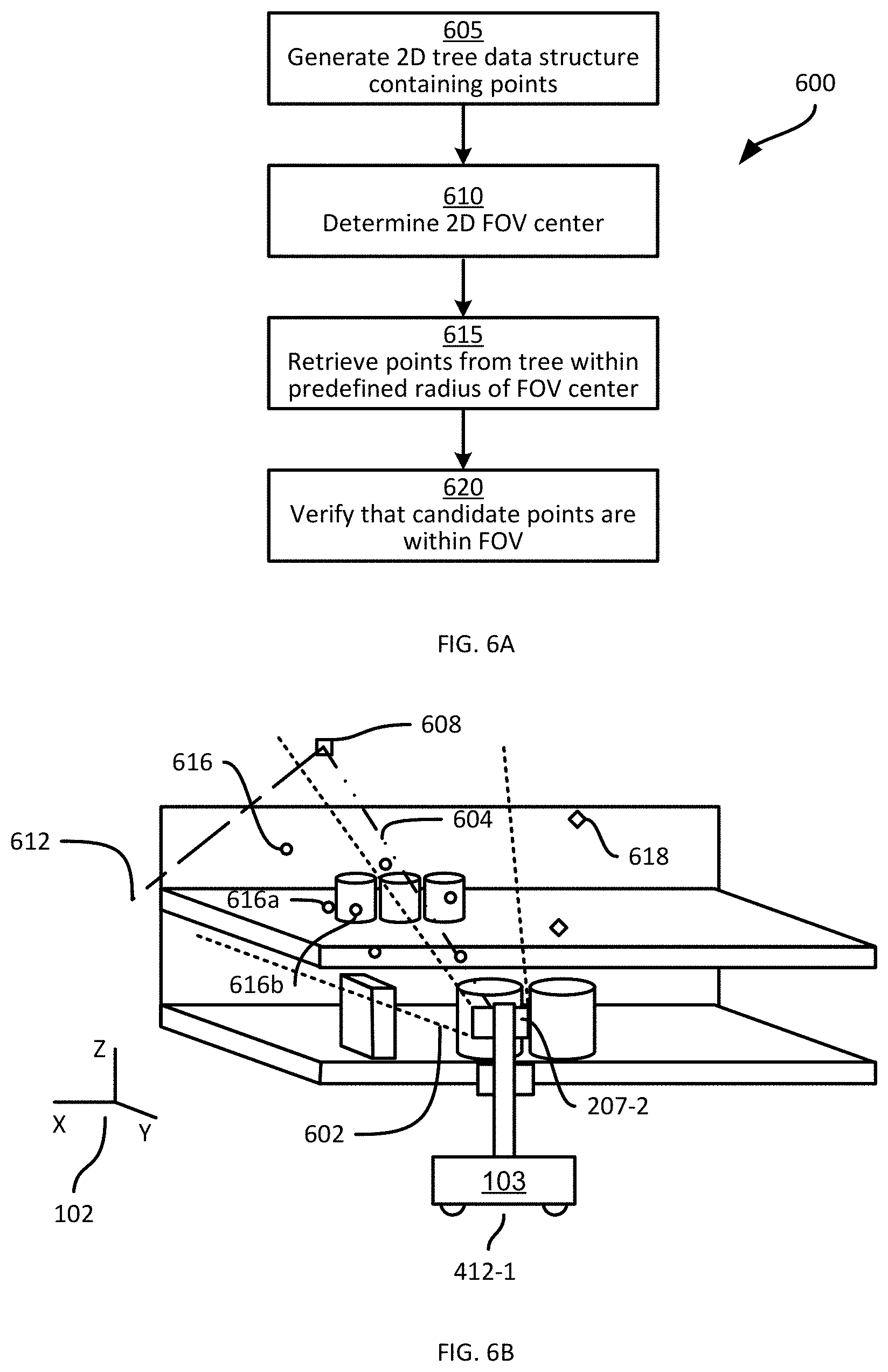
[0053] Turning to FIG. 6A, a method 600 of selecting the initial set of points at block 315. At block 605, the server 101 is configured to generate a tree data structure, such as a k-d (k-dimensional) tree, an octree or the like. In the present example, a k-d tree is generated at block 605. The tree data structure contains, for each point in the point cloud, first and second dimension coordinates orthogonal to the depth of the point. That is, each point is represented in the tree by its X and Z coordinates according to the frame of reference 102, with the Y coordinate being omitted for the selection of the initial set (the Y coordinates are employed later in the method 300, as will be discussed below).
[0054] As will be understood by those skilled in the art, the k-d tree can be constructed by determining the median of one of the two dimensions mentioned above (e.g. the X dimension). Any points with an X coordinate below the median are allocated to a first branch of the tree, while the remaining points are allocated to a second branch. For each branch, the median of the other coordinate (Z, in the present example) is determined and the points allocated to the branch are again subdivided depending on whether their Z coordinates are above or below the Z median. This process is repeated, further subdividing the points between pairs of branches based on alternating dimensional medians (i.e. one division based on the X dimension, followed by one divisional based on the Z dimension, followed by a further division based on the X dimension, and so on), until each node of the tree contains a single point.
[0055] At block 610, the server 101 is configured to determine coordinates of a center of the field of view, in the two dimensions represented in the tree. As noted above, the volume defined by the field of view is determined from operational parameters of the camera 207 and the capture pose. Referring to FIG. 6B, a field of view 602 of the camera 207-2 at the apparatus pose 412-1 is illustrated. The center of the field of view 602, in three dimensions, is defined by the line 604. To determine two-dimensional coordinates of the center of the field of view in two dimensions (i.e. in the X and Z dimensions), the server 101 is configured to select a predefined depth and to determine the coordinates at which the center line 604 intersects the predefined depth. The predefined depth can be stored in the memory 122 as a depth to be added to the depth of the shelf plane obtained at block 305. In other examples, the point cloud, shelf plane, capture poses and the like can be transformed to a frame of reference whose origin lies on the shelf plane itself (e.g. whose XZ plane is on the shelf plane), to simplify the computations discussed herein. As shown in FIG. 6B, the center line 604 intersects the predefined depth at a FOV center 608. The predefined depth is preferably selected to exceed the depth of the shelf back 116 (though the depth of the shelf back 116 may not be known precisely).
[0056] At block 615, the server 101 is configured to select points for the set by retrieving points from the tree that are within a predefined radius of the center 608. FIG. 6B illustrates a predefined radius 612 extending from the center 608. As will now be apparent to those skilled in the art, various mechanisms are available for conducting radius-based searches in trees such as a k-d trees. In the present example, as illustrated in FIG. 6B, points retrieved at block 615 include the example points 616, while other points 618 are not retrieved, as they are further from the center 608 than the radius 612.
[0057] At block 620, the server 101 can be configured to verify that the three-dimensional position of each point retrieved at block 615 falls within the FOV 602, as the predefined radius 612 may extend beyond the actual bounds of the FOV 602. In other examples, block 620 can be omitted. The verification at block 620, when conducted, may employ a transformation matrix, also referred to as a camera calibration matrix, configured to transform 3-dimensional coordinates from the point cloud into two-dimensional coordinates in an image frame of reference (e.g. pixel coordinates within the image 408-1). The verification at block 620 can therefore include, for each point retrieved at block 615, generating the corresponding image coordinates and determining whether the image coordinates are within the bounds of the image 408-1.
[0058] Returning to FIG. 3, having selected the initial set of points 616 within the FOV 602, at block 320 the server 101 is configured to select an unoccluded set of depth measurements from the points in the initial set. The initial set of points selected at block 315, although falling within the FOV 602, may nevertheless include points that were not imaged by the camera 207 because they are occluded from view by the camera 207 by other objects. For example, referring again to FIG. 6B, the point 616a, although within the FOV 602, corresponds to a portion of the shelf 117 that the camera 207-2 cannot image from the capture pose shown in FIG. 6B because a product 112 is between the camera 207-2 and the point 616a. The point 616a may appear in the point cloud because a lidar scanner is positioned differently than the camera 207-2, because a lidar scan captured the point 616a from a subsequent apparatus pose 412, or the like. The point 616a, in other words, is an occluded point for which the image 408-1 and the mask 512 have no corresponding data. At block 320, the server 101 is configured to remove such occluded points from further consideration, and retain data for unoccluded points, such as the point 616b.
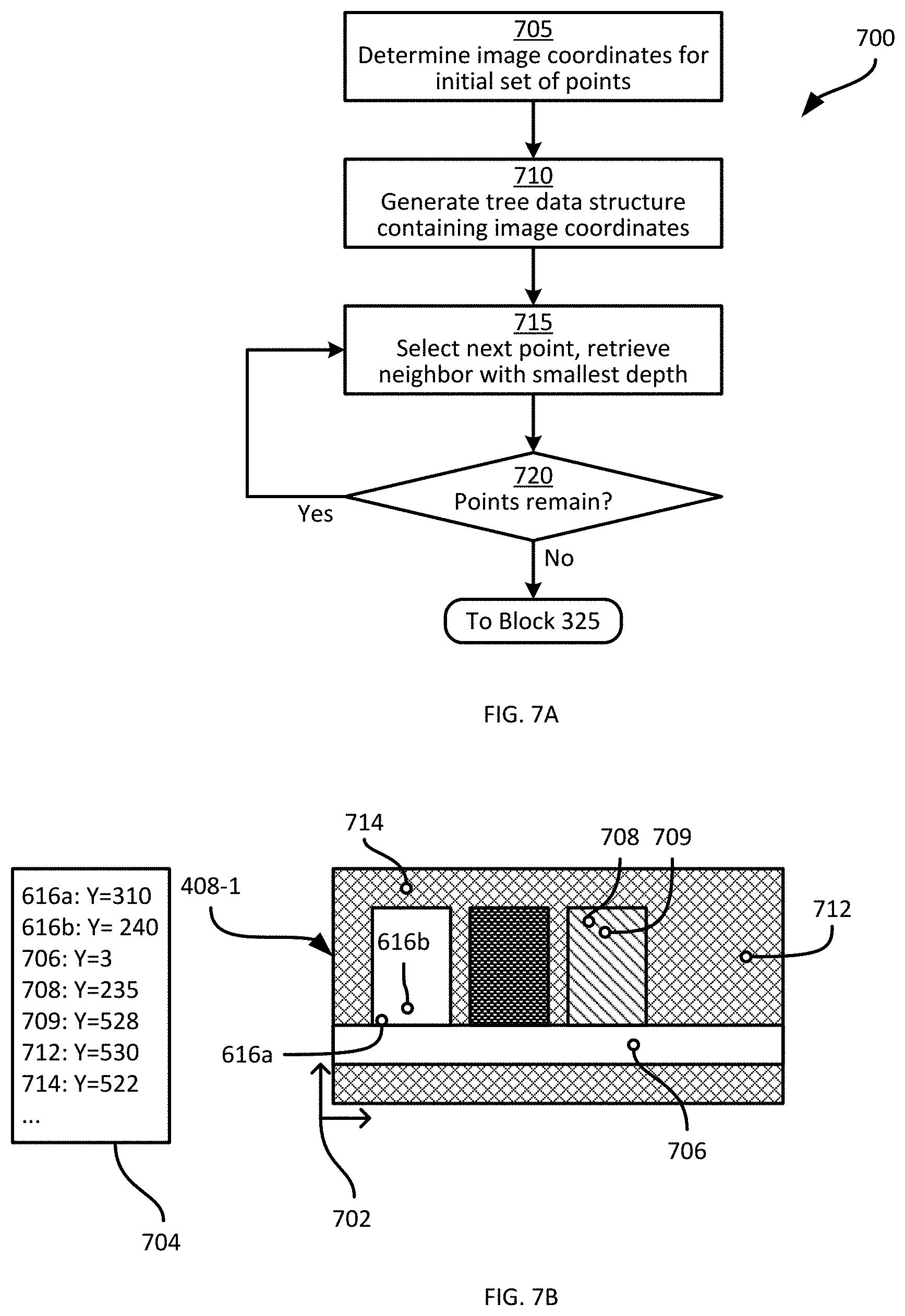
[0059] In general, the selection at block 320 operates on an assumption that for any occluded point from the point cloud, an unoccluded point will also be present in the point cloud corresponding to the object responsible for the occlusion. It is further assumed at block 320 that the unoccluded point mentioned above is visible to the camera 207, and is therefore represented in the image 408-1. Turning to FIG. 7A, an example method 700 of selecting the unoccluded subset of depth measurements is illustrated.
[0060] At block 705, the server 101 is configured to determine the image coordinates for each point in the initial set selected at block 315. As noted above, image coordinates can be obtained by use of the camera calibration matrix in a process also referred to as forward projection (i.e. projecting a point in three dimensions "forward" into a captured image, as opposed to back projection, referred to projecting a point in an image "back" into the point cloud). FIG. 7B illustrates the results of block 705 for the points 616a and 616b discussed earlier. The points 616a and 616b correspond to image coordinates defined according to an image frame of reference 702 (which in the present example is parallel with the XZ plane of the frame of reference 102). As seen in FIG. 7B, the depth measurements in the frame of reference 102 associated with the points 616 are also retained through the performance of the method 700, although they are not directly represented in the image coordinates (which are two-dimensional). The depth measurements may be maintained in a list 704 or other suitable format, in association with the image coordinates. Additional example points 706, 708, 709, 712 and 714 are also illustrated. As shown in the list 704 of depth measurements, the point 708 is located on the surface of a product, while the point 709 is behind the product, e.g. on the shelf back 116 (at a depth of 528 mm, compared to a depth of 235 mm for the point 708). The points 712 and 714 are also located on the shelf back 116, and have associated depths of 530 mm and 522 mm, respectively.
[0061] At block 710, the server 101 is configured to generate a tree data structure, such as a further k-d tree, containing the image coordinates determined at block 705. At block 715, the server 101 is configured to select neighbor groups of points. Specifically, for a selected point in the tree, the server 101 is configured to retrieve the nearest neighbors of that point (e.g. a predefined number of neighbors, neighbors within a predefined radius, or a combination of the above). The server 101 is further configured to select, from the nearest neighbors retrieved at block 715, the neighbor with the smallest depth. Thus, referring again to FIG. 7B and beginning with the point 616a, the nearest neighbor is the point 616b, and the lowest depth between the points 616a and 616b is the depth associated with the point 616b. The depth measurement (as well as the corresponding image coordinates) of the point 616b is therefore retained for inclusion in the unoccluded subset of depth measurements, while the point 616a is discarded. The performance of block 715 is repeated for each remaining point in the initial set, until a determination at block 720 indicates that no points remain to be processed. For the example points shown in FIG. 7B,
[0062] When all points from the initial set have been processed and the subset of unoccluded depth measurements has been selected, the server 101 returns to block 325 of the method 300. At block 325, the server 101 can optionally be configured to select a final subset of depth measurements from the unoccluded subset of depth measurements. For example, taking the points shown in FIG. 7B, the unoccluded subset of depth measurements obtained therefrom is shown in FIG. 8A, in which it is seen that the points 616a and 709 have been discarded from the unoccluded subset 800. At block 325, the server 101 can be configured to perform one or more additional filtering operations to excluded further points from the unoccluded subset.
[0063] A first example of a filtering operation applied at block 325 is to discard any points with a BoS confidence level from the mask 512 that is below a predetermined threshold. The predetermined threshold, in the present example, is 55% (although it will be understood that various other thresholds may be applied instead). FIG. 8B illustrates the mask 512 with confidence levels 816b, 806, 808, 812 and 814 corresponding to the image coordinates of the points 616b, 706, 708, 712 and 714, respectively. In the present example, it is assumed that the confidence levels 816b, 806, 808, 812 and 814 are 30%, 0%, 50%, 100% and 90%, respectively. The points having confidence levels below 55% (that is, the points 616b, 706 and 708) are therefore discarded, and the final subset of depth measurements includes the depth measurements for the points 712 and 714, as well as their associated image coordinates.
[0064] Other examples of filtering performed at block 325 includes discarding points with depth measurements that exceed a predefined maximum depth threshold. FIG. 8C illustrates another example image 818 taken from a different apparatus pose (and therefore a different capture pose) than the pose at which the image 418-1 was captured. In the image 818, an edge 819 of the shelf module 110-3 is visible, and certain points in both the image 818 and the point cloud therefore correspond to areas of the facility beyond the shelf module 110-3. For example, the point 820 may have an associated depth measurement of 2500 mm. The maximum threshold mentioned above may be selected as a maximum known shelf depth throughout the facility (e.g. 700 mm). The point 820 may therefore be discarded at block 325.
[0065] Returning to FIG. 3, at block 330, the depth measurements of the final subset are weighted according to the corresponding confidence levels from the mask 512. Thus, in the present example, the depth measurements for the points 712 and 714 are weighted according to their respective confidence levels (100% and 90%, respectively). For example, the depths may be multiplied by their respective weights (e.g. 530.times.1 and 522.times.0.9). At block 335, the shelf depth is determined from the weighted depths. That is, the shelf depth determined at block 335 is a weighted average of the depth measurements in the final subset from block 325. In the present example, the weighted average of the depth measurements for the points 712 and 714 is obtained by summing the weighted depths, and dividing the result by the sum of the weights (i.e. 1.9 or 190%), yielding a result of 526.2 mm. FIG. 9 illustrates the determined shelf depth as a dashed line 900 extending from the shelf plane 404 (and perpendicular to the shelf plane 404).
[0066] At block 340, the server 101 is configured to determine whether any capture poses remain to be processed (i.e. whether additional apparatus poses for the current camera remain, or whether any additional cameras remain at the current apparatus pose). When the determination at block 340 is affirmative, the performance of the method 300 is repeated for any subsequent images and corresponding masks. When the determination at block 340 is negative, the performance of the method 300 ends. In some examples, block 335 is performed only following a negative determination at block 340, and uses the plurality of weighted final sets of depth measurements from each performance of block 330 to determine a single shelf depth for the shelf module 110. The shelf depth determined via performance of the method 300 can be returned, for example, to a further application of the server 101 (or to another computing device), for use in identifying gaps in the shelves 110 or other object status data.
[0067] In the foregoing specification, specific embodiments have been described. However, one of ordinary skill in the art appreciates that various modifications and changes can be made without departing from the scope of the invention as set forth in the claims below. Accordingly, the specification and figures are to be regarded in an illustrative rather than a restrictive sense, and all such modifications are intended to be included within the scope of present teachings.
[0068] The benefits, advantages, solutions to problems, and any element(s) that may cause any benefit, advantage, or solution to occur or become more pronounced are not to be construed as a critical, required, or essential features or elements of any or all the claims. The invention is defined solely by the appended claims including any amendments made during the pendency of this application and all equivalents of those claims as issued.
[0069] Moreover in this document, relational terms such as first and second, top and bottom, and the like may be used solely to distinguish one entity or action from another entity or action without necessarily requiring or implying any actual such relationship or order between such entities or actions. The terms "comprises," "comprising," "has", "having," "includes", "including," "contains", "containing" or any other variation thereof, are intended to cover a non-exclusive inclusion, such that a process, method, article, or apparatus that comprises, has, includes, contains a list of elements does not include only those elements but may include other elements not expressly listed or inherent to such process, method, article, or apparatus. An element proceeded by "comprises . . . a", "has . . . a", "includes . . . a", "contains . . . a" does not, without more constraints, preclude the existence of additional identical elements in the process, method, article, or apparatus that comprises, has, includes, contains the element. The terms "a" and "an" are defined as one or more unless explicitly stated otherwise herein. The terms "substantially", "essentially", "approximately", "about" or any other version thereof, are defined as being close to as understood by one of ordinary skill in the art, and in one non-limiting embodiment the term is defined to be within 10%, in another embodiment within 5%, in another embodiment within 1% and in another embodiment within 0.5%. The term "coupled" as used herein is defined as connected, although not necessarily directly and not necessarily mechanically. A device or structure that is "configured" in a certain way is configured in at least that way, but may also be configured in ways that are not listed.
[0070] It will be appreciated that some embodiments may be comprised of one or more specialized processors (or "processing devices") such as microprocessors, digital signal processors, customized processors and field programmable gate arrays (FPGAs) and unique stored program instructions (including both software and firmware) that control the one or more processors to implement, in conjunction with certain non-processor circuits, some, most, or all of the functions of the method and/or apparatus described herein. Alternatively, some or all functions could be implemented by a state machine that has no stored program instructions, or in one or more application specific integrated circuits (ASICs), in which each function or some combinations of certain of the functions are implemented as custom logic. Of course, a combination of the two approaches could be used.
[0071] Moreover, an embodiment can be implemented as a computer-readable storage medium having computer readable code stored thereon for programming a computer (e.g., comprising a processor) to perform a method as described and claimed herein. Examples of such computer-readable storage mediums include, but are not limited to, a hard disk, a CD-ROM, an optical storage device, a magnetic storage device, a ROM (Read Only Memory), a PROM (Programmable Read Only Memory), an EPROM (Erasable Programmable Read Only Memory), an EEPROM (Electrically Erasable Programmable Read Only Memory) and a Flash memory. Further, it is expected that one of ordinary skill, notwithstanding possibly significant effort and many design choices motivated by, for example, available time, current technology, and economic considerations, when guided by the concepts and principles disclosed herein will be readily capable of generating such software instructions and programs and ICs with minimal experimentation.
[0072] The Abstract of the Disclosure is provided to allow the reader to quickly ascertain the nature of the technical disclosure. It is submitted with the understanding that it will not be used to interpret or limit the scope or meaning of the claims. In addition, in the foregoing Detailed Description, it can be seen that various features are grouped together in various embodiments for the purpose of streamlining the disclosure. This method of disclosure is not to be interpreted as reflecting an intention that the claimed embodiments require more features than are expressly recited in each claim. Rather, as the following claims reflect, inventive subject matter lies in less than all features of a single disclosed embodiment. Thus the following claims are hereby incorporated into the Detailed Description, with each claim standing on its own as a separately claimed subject matter.
* * * * *
D00000
D00001
D00002
D00003
D00004
D00005
D00006
D00007
D00008
D00009
XML
uspto.report is an independent third-party trademark research tool that is not affiliated, endorsed, or sponsored by the United States Patent and Trademark Office (USPTO) or any other governmental organization. The information provided by uspto.report is based on publicly available data at the time of writing and is intended for informational purposes only.
While we strive to provide accurate and up-to-date information, we do not guarantee the accuracy, completeness, reliability, or suitability of the information displayed on this site. The use of this site is at your own risk. Any reliance you place on such information is therefore strictly at your own risk.
All official trademark data, including owner information, should be verified by visiting the official USPTO website at www.uspto.gov. This site is not intended to replace professional legal advice and should not be used as a substitute for consulting with a legal professional who is knowledgeable about trademark law.