Hvac Compressor With Mixed And Radial Compression Stages
Sun; Lin Xiang ; et al.
U.S. patent application number 16/430848 was filed with the patent office on 2020-04-09 for hvac compressor with mixed and radial compression stages. The applicant listed for this patent is Danfoss A/S. Invention is credited to Hamid Richard Hazby, Christopher John Robinson, Lin Xiang Sun, Jin Yan.
| Application Number | 20200109879 16/430848 |
| Document ID | / |
| Family ID | 68104458 |
| Filed Date | 2020-04-09 |


| United States Patent Application | 20200109879 |
| Kind Code | A1 |
| Sun; Lin Xiang ; et al. | April 9, 2020 |
HVAC COMPRESSOR WITH MIXED AND RADIAL COMPRESSION STAGES
Abstract
A refrigerant compressor according to an exemplary aspect of the present disclosure includes, among other things, a first compression stage arranged in a main refrigerant flow path. The first compression stage is a mixed compression stage having both axial and radial components. The compressor further includes a second compression stage arranged in the main refrigerant flow path downstream of the first compression stage. The second compression stage is a radial compression stage.
| Inventors: | Sun; Lin Xiang; (Tallahassee, FL) ; Yan; Jin; (Tallahassee, FL) ; Hazby; Hamid Richard; (Lincoln, GB) ; Robinson; Christopher John; (Lincoln, GB) | ||||||||||
| Applicant: |
|
||||||||||
|---|---|---|---|---|---|---|---|---|---|---|---|
| Family ID: | 68104458 | ||||||||||
| Appl. No.: | 16/430848 | ||||||||||
| Filed: | June 4, 2019 |
Related U.S. Patent Documents
| Application Number | Filing Date | Patent Number | ||
|---|---|---|---|---|
| 62740464 | Oct 3, 2018 | |||
| Current U.S. Class: | 1/1 |
| Current CPC Class: | F25B 1/053 20130101; F25B 31/026 20130101; F04D 17/12 20130101; F25B 1/10 20130101; F04D 19/028 20130101; F04D 17/06 20130101 |
| International Class: | F25B 1/10 20060101 F25B001/10; F25B 31/02 20060101 F25B031/02 |
Claims
1. A refrigerant compressor, comprising: a first compression stage arranged in a main refrigerant flow path, wherein the first compression stage is a mixed compression stage having both axial and radial components; and a second compression stage arranged in the main refrigerant flow path downstream of the first compression stage, wherein the second compression stage is a radial compression stage.
2. The refrigerant compressor as recited in claim 1, wherein the first compression stage is arranged such that fluid is configured to flow therethrough along a direction inclined relative to an axis of rotation of the refrigerant compressor.
3. The refrigerant compressor as recited in claim 2, wherein the direction is inclined at an angle of less than 45.degree. relative to the axis of rotation of the refrigerant compressor.
4. The refrigerant compressor as recited in claim 1, wherein: the main refrigerant flow path is defined between an outer wall and an inner wall, adjacent an inlet of the first compression stage, the outer wall and inner wall are radially spaced-apart from one another by a first radial distance, and adjacent an outlet of the first compression stage, the outer wall and inner wall are radially spaced-apart from one another by a second radial distance less than the first radial distance.
5. The refrigerant compressor as recited in claim 4, wherein the outer wall and the inner wall are curved within the first compression stage.
6. The refrigerant compressor as recited in claim 5, wherein, within the first compression stage, the outer wall and the inner wall are concave when viewed from a radially outer location.
7. The refrigerant compressor as recited in claim 5, wherein the outer wall and the inner wall have inflection points and smoothly transition such that the outer wall and the inner wall are substantially parallel to one another between the first compression stage and the second compression stage.
8. The refrigerant compressor as recited in claim 7, wherein an array of static diffuser vanes is arranged in the main refrigerant flow path between the first compression stage and the second compression stage.
9. The refrigerant compressor as recited in claim 1, wherein the second compression stage includes an impeller configured to turn a substantial axial flow to a substantial radial flow.
10. The refrigerant compressor as recited in claim 1, wherein the main refrigerant flow path makes a substantially 180 degree turn between the first and second compression stages.
11. The refrigerant compressor as recited in claim 10, wherein the main refrigerant flow path includes a cross-over bend between the first and second compression stages.
12. The refrigerant compressor as recited in claim 11, wherein deswirl vanes are arranged within the main refrigerant flow path downstream of the cross-over bend and upstream of the second compression stage.
13. The refrigerant compressor as recited in claim 1, wherein the refrigerant compressor is used in a heating, ventilation, and air conditioning (HVAC) chiller system.
14. A refrigerant system comprising: a main refrigerant loop including a compressor, a condenser, an evaporator, and an expansion device, wherein the compressor includes: a first compression stage arranged in a main refrigerant flow path, wherein the first compression stage is a mixed compression stage having both axial and radial components; and a second compression stage arranged in the main refrigerant flow path downstream of the first compression stage, wherein the second compression stage is a radial compression stage.
15. The refrigerant system as recited in claim 14, wherein the first compression stage is arranged such that fluid is configured to flow therethrough along a direction inclined relative to an axis of rotation of the refrigerant compressor at an angle of less than 45.degree. relative to the axis of rotation of the refrigerant compressor.
16. The refrigerant system as recited in claim 14, wherein: the main refrigerant flow path is defined between an outer wall and an inner wall, and the outer wall and the inner wall are curved within the first compression stage such that the outer wall and inner wall are concave when viewed from a radially outer location.
17. The refrigerant system as recited in claim 14, wherein an array of static diffuser vanes is arranged in the main refrigerant flow path between the first compression stage and the second compression stage.
18. The refrigerant system as recited in claim 14, wherein the second compression stage includes an impeller configured to turn a substantial axial flow to a substantial radial flow.
19. The refrigerant system as recited in claim 14, wherein the main refrigerant flow path makes a substantially 180 degree turn between the first and second compression stages.
20. The refrigerant system as recited in claim 14, wherein the refrigerant system is a heating, ventilation, and air conditioning (HVAC) chiller system.
Description
TECHNICAL FIELD
[0001] This disclosure relates to a compressor having a mixed compression stage and a radial compression stage. The compressor is used in a heating, ventilation, and air conditioning (HVAC) chiller system, for example.
BACKGROUND
[0002] Refrigerant compressors are used to circulate refrigerant in a chiller via a refrigerant loop. Refrigerant loops are known to include a condenser, an expansion device, and an evaporator. The compressor compresses the fluid, which then travels to a condenser, which in turn cools and condenses the fluid. The refrigerant then goes to an expansion device, which decreases the pressure of the fluid, and to the evaporator, where the fluid is vaporized, completing a refrigeration cycle.
[0003] Many refrigerant compressors are centrifugal compressors and have an electric motor that drives at least one impeller to compress refrigerant. Fluid flows into the impeller in an axial direction, and is expelled radially from the impeller. The fluid is then directed downstream for use in the chiller system.
SUMMARY
[0004] A refrigerant compressor according to an exemplary aspect of the present disclosure includes, among other things, a first compression stage arranged in a main refrigerant flow path. The first compression stage is a mixed compression stage having both axial and radial components. The compressor further includes a second compression stage arranged in the main refrigerant flow path downstream of the first compression stage. The second compression stage is a radial compression stage.
[0005] In a further embodiment, the first compression stage is arranged such that fluid is configured to flow therethrough along a direction inclined relative to an axis of rotation of the refrigerant compressor.
[0006] In a further embodiment, the direction is inclined at an angle of less than 45.degree. relative to the axis of rotation of the refrigerant compressor.
[0007] In a further embodiment, the main refrigerant flow path is defined between an outer wall and an inner wall. Further, adjacent an inlet of the first compression stage, the outer wall and inner wall are radially spaced-apart from one another by a first radial distance, and adjacent an outlet of the first compression stage, the outer wall and inner wall are radially spaced-apart from one another by a second radial distance less than the first radial distance.
[0008] In a further embodiment, the outer wall and the inner wall are curved within the first compression stage.
[0009] In a further embodiment, within the first compression stage, the outer wall and the inner wall are concave when viewed from a radially outer location.
[0010] In a further embodiment, the outer wall and the inner wall have inflection points and smoothly transition such that the outer wall and the inner wall are substantially parallel to one another between the first compression stage and the second compression stage.
[0011] In a further embodiment, an array of static diffuser vanes is arranged in the main refrigerant flow path between the first compression stage and the second compression stage.
[0012] In a further embodiment, the second compression stage includes an impeller configured to turn a substantial axial flow to a substantial radial flow.
[0013] In a further embodiment, the main refrigerant flow path makes a substantially 180 degree turn between the first and second compression stages.
[0014] In a further embodiment, the main refrigerant flow path includes a cross-over bend between the first and second compression stages.
[0015] In a further embodiment, deswirl vanes are arranged within the main refrigerant flow path downstream of the cross-over bend and upstream of the second compression stage.
[0016] In a further embodiment, the refrigerant compressor is used in a heating, ventilation, and air conditioning (HVAC) chiller system.
[0017] A refrigerant system according to an exemplary aspect of the present disclosure includes, among other things, a main refrigerant loop including a compressor, a condenser, an evaporator, and an expansion device. The compressor includes a first compression stage arranged in a main refrigerant flow path. The first compression stage is a mixed compression stage having both axial and radial components. Further, a second compression stage is arranged in the main refrigerant flow path downstream of the first compression stage. The second compression stage is a radial compression stage.
[0018] In a further embodiment, the first compression stage is arranged such that fluid is configured to flow therethrough along a direction inclined relative to an axis of rotation of the refrigerant compressor at an angle of less than 45.degree. relative to the axis of rotation of the refrigerant compressor.
[0019] In a further embodiment, the main refrigerant flow path is defined between an outer wall and an inner wall, and the outer wall and the inner wall are curved within the first compression stage such that the outer wall and inner wall are concave when viewed from a radially outer location.
[0020] In a further embodiment, an array of static diffuser vanes is arranged in the main refrigerant flow path between the first compression stage and the second compression stage.
[0021] In a further embodiment, the second compression stage includes an impeller configured to turn a substantial axial flow to a substantial radial flow.
[0022] In a further embodiment, the main refrigerant flow path makes a substantially 180 degree turn between the first and second compression stages.
[0023] In a further embodiment, the refrigerant system is a heating, ventilation, and air conditioning (HVAC) chiller system.
BRIEF DESCRIPTION OF THE DRAWINGS
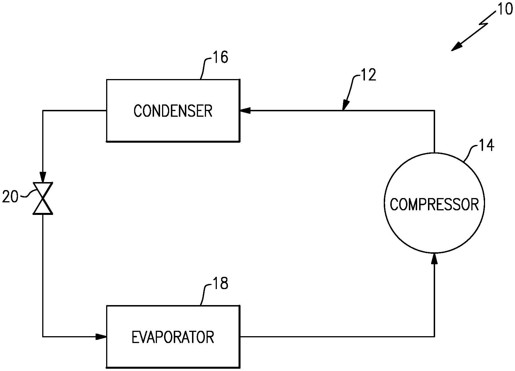
[0024] FIG. 1 schematically illustrates a refrigerant system.
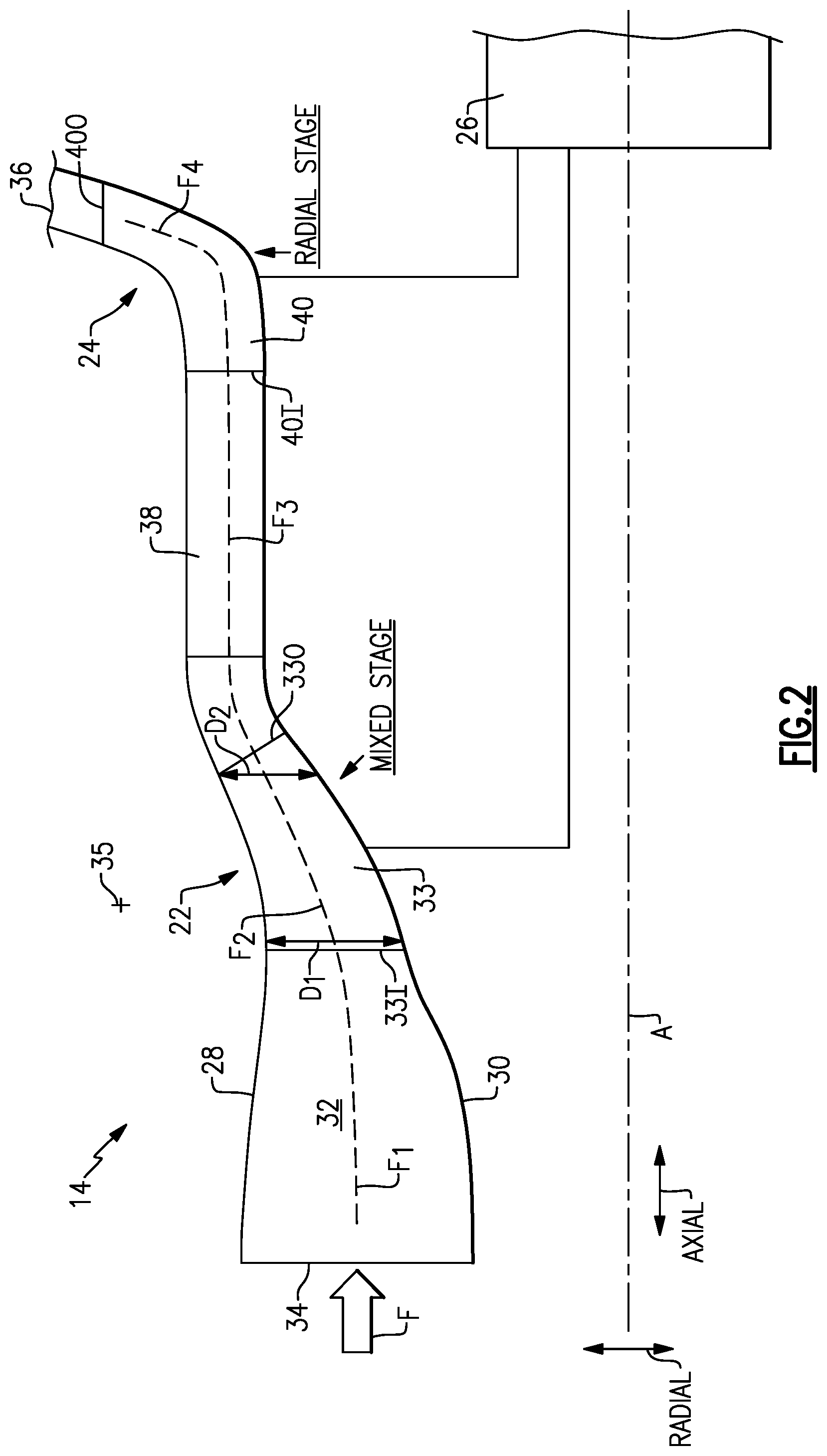
[0025] FIG. 2 schematically illustrates a first example compressor having two compression stages, with a first compression stage being a mixed compression stage and a second compression stage being a radial compression stage.
[0026] FIG. 3 schematically illustrates a second example compressor having two compression stages, with a first compression stage being a mixed compression stage and a second compression stage being a radial compression stage.
DETAILED DESCRIPTION
[0027] FIG. 1 illustrates a refrigerant system 10. The refrigerant system 10 includes a main refrigerant loop, or circuit, 12 in communication with a compressor 14, a condenser 16, an evaporator 18, and an expansion device 20. This refrigerant system 10 may be used in a chiller, for example. In that example, a cooling tower may be in fluid communication with the condenser 16. While a particular example of the refrigerant system 10 is shown, this application extends to other refrigerant system configurations, including configurations that do not include a chiller. For instance, the main refrigerant loop 12 can include an economizer downstream of the condenser 16 and upstream of the expansion device 20.
[0028] FIG. 2 schematically illustrates a first example example refrigerant compressor according to this disclosure. In FIG. 2, a portion of the compressor 14 is shown in cross-section. It should be understood that FIG. 2 only illustrates an upper portion of the compressor 14, and that the compressor 14 would essentially include the same structure reflected about its central longitudinal axis A.
[0029] In this example, the compressor 14 has two compression stages 22, 24 spaced-apart from one another along the axis A. The compression stages 22, 24 each include a plurality of blades (e.g., an array of blades) arranged on a disk, for example, and rotatable about the axis A via a motor 26. In this example, the motor 26 is an electric motor arranged about the axis A. The compression stages 22, 24 may be coupled to the motor 26 by separate shafts or by a common shaft. Two shafts are shown schematically in FIG. 2.
[0030] The compressor 14 includes an outer wall 28 and an inner wall 30 which together bound a main flow path 32. The main flow path 32 extends between an inlet 34 and an outlet 36 of the compressor 14. The outer and inner walls 28, 30 may be provided by one or more structures.
[0031] Between the inlet 34 and the first compression stage 22, fluid F within the main flow path 32 flows in a first direction F.sub.1, which is an axial direction substantially parallel to the axis A. The "axial" direction is labeled in FIG. 2 for reference. The fluid F is refrigerant in this disclosure.
[0032] The first compression stage 22 includes a plurality of blades 33 arranged for rotation about the axis A. Adjacent the inlet 331 of the first compression stage 22, the outer and inner walls 28, 30 are spaced-apart by a radial distance D.sub.1. Adjacent the outlet 330 of the first compression stage 22, the outer and inner walls 28, 30 are spaced-apart by a radial distance D.sub.2, which is less than D.sub.1. The distances D.sub.1 and D.sub.2 are measured normally to the axis A.
[0033] Within the first compression stage 22, the outer and inner walls 28, 30 are arranged such that the fluid F is directed in a second direction F.sub.2, which has both axial and radial components. In this regard, the first compression stage 22 may be referred to as a "mixed" compression stage, because the fluid F within the first compression stage 22 has both axial and radial flow components. The "radial" direction is labeled in FIG. 2 for reference.
[0034] In one example, the second direction F.sub.2 is inclined at an angle of less than 45.degree. relative to the first direction F.sub.1 and relative to the axis A. In this way, the second direction F.sub.2 is primarily axial but also has a radial component (i.e., the axial component is greater than the radial component).
[0035] Further, between the inlet 331 and outlet 330, the inner and outer walls 28, 30 are not straight. Rather, the inner and outer walls 28, 30 are curved. Specifically, in this example, the inner and outer walls 28, 30 are curved such that they are generally concave within the first compression stage 22 when viewed from a radially outer location, such as the location 35 in FIG. 2. Thus, the fluid F smoothly transitions from a purely axial flow to a mixed flow having both axial and radial components.
[0036] Downstream of the first compression stage 22, the outer and inner walls 28, 30 have inflection points and smoothly transition such that they are substantially parallel to one another. As such, the fluid F is directed in a third direction F.sub.3, which is substantially parallel to both the first direction F.sub.1 and the axis A. As the fluid F is flowing in the third direction F.sub.3, the fluid F also flows through an array of static diffuser vanes 38 in this example.
[0037] Downstream of the diffuser vanes 38, the fluid F is directed to the second compression stage 24, which in this example includes an impeller 40 configured to turn the fluid F flowing in a substantially axial direction to a substantially radial direction. In particular, the impeller 40 includes an inlet 401 arranged axially, substantially parallel to the axis A, and an outlet 400 arranged radially, substantially perpendicular to the axis A.
[0038] In particular, the fluid F enters the second compression stage 24 flowing in the third direction F.sub.3 and exits the second compression stage 24 flowing in a fourth direction F.sub.4, which in one example is substantially parallel to the radial direction. In this disclosure, the fourth direction F.sub.4 is inclined relative to the axis A at an angle greater than 45.degree. and less than or equal to 90.degree.. In one particular example, the fourth direction F.sub.4 is substantially equal to 90.degree.. In this way, the second stage compression 24 may be referred to as a radial compression stage.
[0039] The combination of the first compression stage 22 having both axial and radial components (i.e., second direction F.sub.2 is inclined at less than 45.degree.) with the second compression stage 24 being primarily radial (i.e., the fourth direction F.sub.4 is substantially equal to 90.degree.), the compressor 14 is more compact than a compressor that includes two radial impellers, for example. The compressor 14 also exhibits an increased operating range, in that it can operate without surging at lower capacities, relative to compressors with two axial impellers. Accordingly, the compressor 14 strikes a unique balance between being compact and efficient.
[0040] FIG. 3 schematically illustrates a second example refrigerant compressor according to this disclosure. To the extent not otherwise described or shown, the compressor 114 corresponds to the compressor 14 of FIG. 2, with like parts having reference numerals preappended with a "1."
[0041] Like the compressor 14, the compressor 114 has two compression stages 122, 124 spaced-apart from one another along an axis A. The first compression stage 122 is a "mixed" compression stage and is arranged substantially similar to the first compression stage 22. The second compression stage 124 is a radial compression stage and is likewise arranged substantially similar to the second compression stage 24.
[0042] Unlike the compressor 14, the main flow path 132 of the compressor 114 includes a 180-degree bend between the first and second compression stages 122, 124. Specifically, downstream of the first compression stage 122, the main flow path 132 turns and projects radially outward from the axis A. Specifically, the main flow path 132 is substantially normal to the axis A within a first section 190. The main flow path 132 turns again by substantially 180 degrees in a cross-over bend 192, such that the main flow path 132 projects radially inward toward the axis A in a second section 194, which may be referred to as a return channel. The second section includes deswirl vanes 196 in this example, which ready the flow of fluid F for the second compression stage 124. Further, downstream of the second compression stage 124, the compressor 114 includes an outlet volute 198 which spirals about the axis A and leads to a compressor outlet. The compressor 14 may also include an outlet volute.
[0043] It should be understood that terms such as "axial" and "radial" are used above with reference to the normal operational attitude of a compressor. Further, these terms have been used herein for purposes of explanation, and should not be considered otherwise limiting. Terms such "generally," "about," and "substantially" are not intended to be boundaryless terms, and should be interpreted consistent with the way one skilled in the art would interpret those terms.
[0044] Although the different examples have the specific components shown in the illustrations, embodiments of this disclosure are not limited to those particular combinations. It is possible to use some of the components or features from one of the examples in combination with features or components from another one of the examples.
[0045] One of ordinary skill in this art would understand that the above-described embodiments are exemplary and non-limiting. That is, modifications of this disclosure would come within the scope of the claims. Accordingly, the following claims should be studied to determine their true scope and content.
* * * * *
D00000
D00001
D00002
D00003
XML
uspto.report is an independent third-party trademark research tool that is not affiliated, endorsed, or sponsored by the United States Patent and Trademark Office (USPTO) or any other governmental organization. The information provided by uspto.report is based on publicly available data at the time of writing and is intended for informational purposes only.
While we strive to provide accurate and up-to-date information, we do not guarantee the accuracy, completeness, reliability, or suitability of the information displayed on this site. The use of this site is at your own risk. Any reliance you place on such information is therefore strictly at your own risk.
All official trademark data, including owner information, should be verified by visiting the official USPTO website at www.uspto.gov. This site is not intended to replace professional legal advice and should not be used as a substitute for consulting with a legal professional who is knowledgeable about trademark law.