Integrated Rotary Positive-displacement Machinery
HUANG; Paul Xiubao ; et al.
U.S. patent application number 16/155021 was filed with the patent office on 2020-04-09 for integrated rotary positive-displacement machinery. This patent application is currently assigned to HI-BAR BLOWERS, INC.. The applicant listed for this patent is HI-BAR BLOWERS, INC.. Invention is credited to Paul Xiubao HUANG, Sean William YONKERS.
| Application Number | 20200109713 16/155021 |
| Document ID | / |
| Family ID | 70052107 |
| Filed Date | 2020-04-09 |


View All Diagrams
| United States Patent Application | 20200109713 |
| Kind Code | A1 |
| HUANG; Paul Xiubao ; et al. | April 9, 2020 |
INTEGRATED ROTARY POSITIVE-DISPLACEMENT MACHINERY
Abstract
Integrated rotary positive-displacement machinery, for example compressors and/or vacuum pumps, include a compressor core equipped with at least one shunt pulsation trap and at least one absorptive silencer integrated together along with other compressor components (such as inlet/outlet pulsation dampeners, gas filters, safety valves, etc.) into a unit or package with a reduced pulsation, noise, energy consumption, and size and weight. Some embodiments further include at least one 4-way valve and corresponding piping so that the same positive-displacement machine can be operated to selectively provide vacuum and pressure by operation of the valve and piping.
| Inventors: | HUANG; Paul Xiubao; (Fayetteville, GA) ; YONKERS; Sean William; (Peachtree City, GA) | ||||||||||
| Applicant: |
|
||||||||||
|---|---|---|---|---|---|---|---|---|---|---|---|
| Assignee: | HI-BAR BLOWERS, INC. Fayetteville GA |
||||||||||
| Family ID: | 70052107 | ||||||||||
| Appl. No.: | 16/155021 | ||||||||||
| Filed: | October 9, 2018 |
| Current U.S. Class: | 1/1 |
| Current CPC Class: | F04C 29/063 20130101; F04C 18/126 20130101; F04C 18/12 20130101; F04C 29/12 20130101; F04C 29/0035 20130101; F04C 18/18 20130101 |
| International Class: | F04C 29/00 20060101 F04C029/00; F04C 18/18 20060101 F04C018/18; F04C 29/12 20060101 F04C029/12 |
Claims
1. An integrated rotary positive-displacement machine (IRPDC), comprising: a compressor core having a compressor cavity having a gas flow suction port and a gas flow discharge port, and at least two rotors mounted in the compressor cavity and driven in a compression phase to reduce the compressor cavity gas volume and propel gas flow from the suction port to the discharge port; a shunt pulsation trap including a trap chamber positioned adjacent to the compressor cavity, at least one pulsation dampener positioned within the trap chamber, at least one trap inlet branching off from the compressor cavity into the pulsation trap chamber, and at least one trap outlet communicating with the compressor discharge port; and an integrated absorptive silencer including at least one folded flow channel and noise-absorbing material, with the at least one folded flow channel interfaced directly with at least one of the suction or discharge ports of the compressor core and at one end and open to atmosphere at the other end, wherein in operation the IRPDC achieves both low-frequency gas pulsation and high-frequency noise reduction at source and improves compressor off-design efficiency without using a traditional serial pulsation dampener.
2. The IRPDC as claimed in claim 1, wherein the at least one flow channel of the absorptive dampener has a folded configuration with at least one turn equal to or larger than 90 degrees.
3. The IRPDC as claimed in claim 1, wherein the at least one flow channel of the absorptive dampener has a folded shape and at least one said wall that is perforated and lined with the noise-absorbing material.
4. The IRPDC as claimed in claim 1, wherein the at least one flow channel of the absorptive dampener has parallel walls with no sudden change in cross-sectional area.
5. The IRPDC as claimed in claim 4, wherein the at least one flow channel interfaces directly with at least one of said flow ports of said compressor core, and wherein the at least one flow channel and the interfaced flow port of said compressor have a same cross-sectional shape.
6. The IRPDC as claimed in claim 4, wherein the integrated absorptive silencer includes a flow divider where the at least one flow channel interfaces directly with the interfaced flow port of said compressor core, wherein said at least one flow channel is divided into two flow channels by the divider.
7. The IRPDC as claimed in claim 6, wherein said two flow channels meet again with a flow channel length difference of 1/4 wavelength.
8. The IRPDC as claimed in claim 6, wherein said flow channel divider has a protruding lip.
9. The IRPDC as claimed in claim 1, wherein said absorptive dampener is separated from said compressor core by an inlet dampener.
10. The IRPDC as claimed in claim 9, wherein the inlet dampener has at least one layer of perforated and curved surface.
11. An integrated rotary positive-displacement machine (IRPDC), comprising: a compressor core having a gas flow suction port, a gas flow discharge port, and a compressor cavity formed with at least two rotors mounted inside said compressor cavity and driven in a compression phase to reduce said compressor cavity gas volume and propel gas flow from said suction port to said discharge port; a shunt pulsation trap comprising a trap chamber positioned adjacent to said compressor cavity, at least one pulsation dampener positioned within said trap chamber, at least one trap inlet branching off from said compressor cavity into said pulsation trap chamber, and at least one trap outlet communicating with atmosphere; and at least one integrated absorptive silencer comprising at least one folded flow channel and noise-absorbing material interfaced directly with at least one of said trap outlets and/or the discharge port of said compressor core on one end and/or with atmosphere on the other end; wherein in operation said IRPDC achieves both low-frequency gas pulsation and high-frequency noise reduction at source and improves compressor off-design efficiency without using at least one traditional serial pulsation dampener.
12. The IRPDC as claimed in claim 11, wherein the at least one flow channel of the absorptive dampener has a folded configuration with at least one turn equal to or larger than 90 degrees.
13. The IRPDC as claimed in claim 11, wherein the at least one flow channel of the absorptive dampener has at least one said wall that is perforated and lined with the noise-absorbing material.
14. The IRPDC as claimed in claim 11, wherein the at least one flow channel interfaces directly with at least one of said flow ports of said compressor core, and wherein the at least one flow channel and the interfaced flow port of said compressor have a same cross-sectional shape.
15. The IRPDC as claimed in claim 11, wherein the integrated absorptive silencer includes a flow divider where the at least one flow channel interfaces directly with the interfaced flow port of said compressor core, wherein said at least one flow channel i is divided into two flow channels by the divider.
16. An integrated rotary positive-displacement machine (IRPDC), comprising: a compressor core having a gas flow suction port, a gas flow discharge port, and a compressor cavity formed with at least two rotors mounted inside said compressor cavity and driven in a compression phase to reduce said compressor cavity gas volume and propel gas flow from said suction port to said discharge port; a shunt pulsation trap including a trap chamber positioned adjacent to the compressor cavity, at least one trap inlet branching off from the compressor cavity into the pulsation trap chamber, and at least one trap outlet communicating with the compressor discharge port; and a first 4-way valve located in front of the compressor core and having four ports, wherein with the first 4-way valve set for a vacuum mode a system port connecting to an external system is connected with the compressor core suction port and an atmosphere port connecting to atmosphere is connected with the compressor core discharge port, and wherein the first 4-way valve can be switched to a pressure mode with the system now connecting with the compressor core discharge port through the SPT and the atmosphere port now connecting with the compressor core suction port, wherein in operation said IRPDC achieves a dual-purpose machine for both pressure and vacuum functionality.
17. The IRPDC as claimed in claim 16, wherein at least one pulsation dampener is positioned within the trap chamber.
18. The IRPDC as claimed in claim 16, further comprising an integrated absorptive silencer comprising at least one folded flow channel and noise-absorbing material interfaced directly with at least one of said trap outlets and/or the discharge port of said compressor core.
19. The IRPDC as claimed in claim 16, wherein the shunt pulsation trap outlet communicates with atmosphere by a second 4-way valve having four ports, wherein the second 4-way valve can be switched to a deep vacuum mode corresponding to the first 4-way valve set for the vacuum mode when it is open to atmosphere, and switched to the pressure mode corresponding to the first 4-way valve set for the pressure mode when it is closed to atmosphere.
20. The IRPDC as claimed in claim 19, further comprising an integrated absorptive silencer comprising at least one folded flow channel and noise-absorbing material interfaced directly with at least one of said trap outlets and/or the discharge port of said compressor core.
Description
TECHNICAL FIELD
[0001] The present invention relates generally to the field of positive-displacement machinery, and more particularly to improved noise reduction for positive-displacement gas-transfer machinery.
BACKGROUND
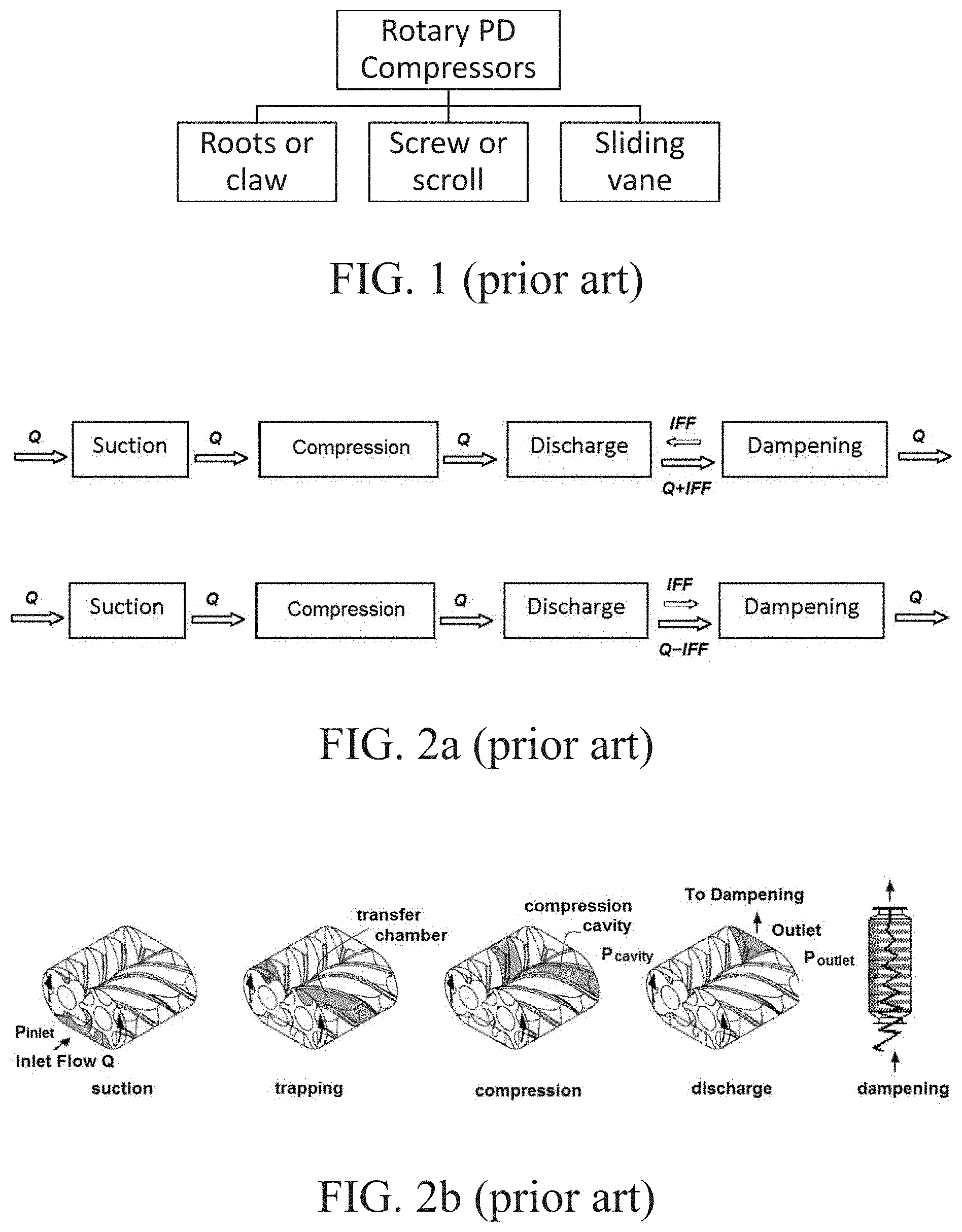
[0002] Conventional rotary positive-displacement compressors (RPDCs) include compressors and vacuum pumps of several types such as Roots, claw, sliding-vane, screw, and scroll machinery, as shown in FIG. 1. RPDCs use various types of rotary positive-displacement mechanisms housed in a compressor core to compress a wide range of gases. RPDCs are widely used in many different industries, including chemical and petrochemical, food processing, power generation, natural and process gas applications, refrigeration, and in vapor-recovery services. When operating at off-design conditions such as over-compression or under-compression, they inherently generate high amplitude pulsating pressures (e.g., up to 180-200 dB), and to address this prior-art RPDCs typically include a reactive or combination-type dampener or silencer (see, e.g., FIGS. 2b, 2c, and 2e) configured in series after discharge to suppress both the low-frequency gas pulsations and the high-frequency noises. However, this serial dampening scheme suffers a sizable back-pressure loss or requires a considerably larger-sized dampener to reduce this loss. Growing global demand to simultaneously meet higher efficiency, smaller size, and lower noise for these systems is conflicting with the governing rule of conventional serial dampening (see, e.g., FIG. 2a) employed for the past 100 years: more noise reduction equates to more back-pressure loss and larger size.
[0003] Conventional shunt pulsation trap (SPT) technology attempts to address this problem by tackling the inherent pressure pulses before discharge, for example as shown in FIG. 3a. Details of SPT technology are disclosed for example in several co-owned patents (U.S. Pat. Nos. 9,140,260; 9,151,292; 9,140,261; 9,243,557; 9,551,342; and 9,732,754, all of which are hereby incorporated herein by reference). Conventional SPT technology is very effective in suppressing the low-frequency pressure pulsation levels by at least about 10-fold (see, e.g., FIG. 3b) and reducing the energy consumption by about 5-16% (see, e.g., FIG. 3c) due to the elimination of the back-pressure loss inherent with serial dampening. The dampener size of conventional SPTs can also be reduced by at least about 5-fold by integrating the SPT with the compressor core (see, e.g., FIG. 3b). However, current SPT technology does not sufficiently reduce the high-frequency noises at the same time.
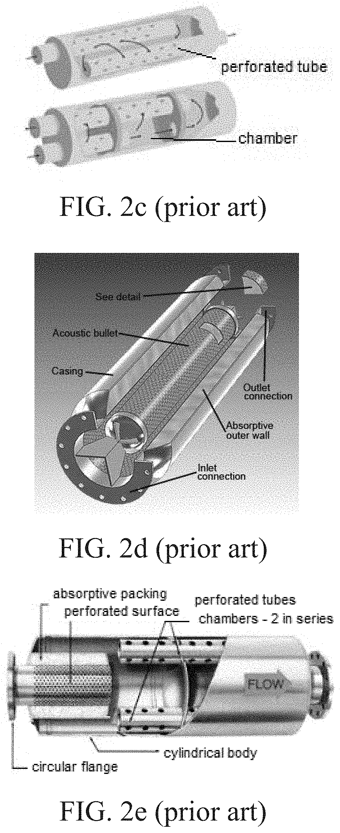
[0004] Conventional absorptive silencers are very effective in controlling high-frequency noises by lining perforated flow-channel walls with sound-absorbing materials, as shown in FIG. 2d. Industrial absorptive silencers are typically constructed in a cylindrical shape and connected to an RPDC discharge flange that often results in a considerably larger cross-sectional size than the RPDC itself. Typically, additional RPDC components are included, such as filters, valves, process control systems, and related plumbing, which further increases not only the package size, but also the weight and cost of the system. The challenge is to simultaneously reduce gas pulsation, noise, energy, and size for RPDC machinery.
[0005] For mobile applications such as liquid tank haulers, it is often required to have both vacuum to load and pressure to unload the system. Typically, these systems include two positive-displacement machines, with one operating as a vacuum pump and the other operating as a compressor, with corresponding noise-reduction systems that are bulky and costly. The challenge here is to use one small system to do both vacuum and pressure duties while simultaneously reducing gas pulsation, noise, space, and weight, with the space and weight factors being particularly important for mobile applications.
[0006] Accordingly, it can be seen that needs exist for improved positive-displacement machinery. It is to the provision of solutions to these and other problems that the present invention is primarily directed.
SUMMARY
[0007] Integrated rotary positive-displacement machinery, for example compressors and/or vacuum pumps, include a compressor core equipped with at least one shunt pulsation trap and at least one absorptive silencer integrated together along with other compressor components (such as inlet/outlet pulsation dampeners, gas filters, safety valves, etc.) into a unit or package with a reduced size and weight. Some embodiments further include at least one 4-way valve and corresponding piping so that the same positive-displacement machine can be operated to selectively provide vacuum and pressure by operation of the valve and piping.
[0008] The specific techniques and structures employed to improve over the drawbacks of the prior devices and accomplish the advantages described herein will become apparent from the following detailed description of example embodiments and the appended drawings and claims.
BRIEF DESCRIPTION OF THE DRAWINGS
[0009] FIG. 1 shows a classification chart of prior-art rotary positive-displacement compressors and vacuum pumps (RPDC).
[0010] FIG. 2a is two flow charts of the phases of a prior-art compression cycle with serial dampening, showing under compression (top flow chart) and over compression (bottom flow chart).
[0011] FIG. 2b is a series of perspective views of a prior-art screw compressor showing the phases of the prior-art compression cycle with serial dampening generally corresponding to FIG. 2a.
[0012] FIG. 2c is two perspective views, in partial cutaway, of two prior-art serial reactive silencers.
[0013] FIG. 2d is a perspective view, in partial cutaway, of a prior-art serial absorptive silencer.
[0014] FIG. 2e is a perspective view, in partial cutaway, of a prior-art serial combination reactive/absorptive silencer.
[0015] FIG. 3a is two flow charts of the phases of a prior-art compression cycle with a shunt pulsation trap, showing under-compression (top flow chart) and over-compression (bottom flow chart).
[0016] FIG. 3b is a cross-sectional view of a prior-art Roots compressor with a shunt pulsation trap, showing the triggering moment at the trap inlet suddenly opening.
[0017] FIG. 3c is a P-V diagram of serial dampening (with back pressure) and shunt pulsation trapping (without back pressure) compared to show work savings.
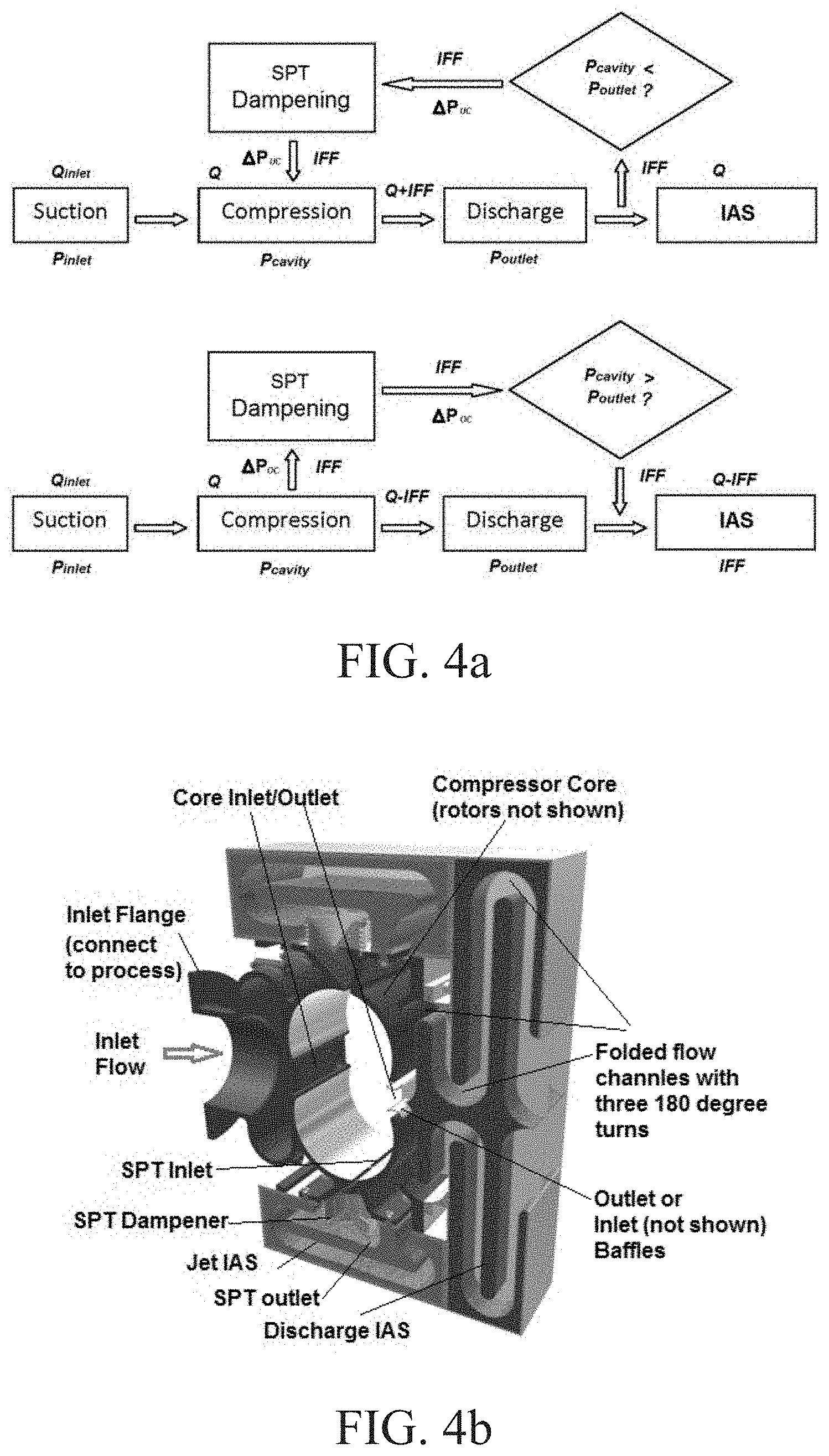
[0018] FIG. 4a is two flow charts of the phases of a compression cycle of an integrated rotary positive-displacement compressor (IRPDC) with a shunt pulsation trap (SPT) and an integrated absorptive silencer (IAS) according to a first example embodiment of the present invention, showing under-compression (top flow chart) and over-compression (bottom flow chart).
[0019] FIG. 4b is a perspective cross-sectional view of an IRPDC with an SPT and an IAS according to FIG. 4a (top flow chart), showing jet IAS and discharge IAS in a vacuum mode.
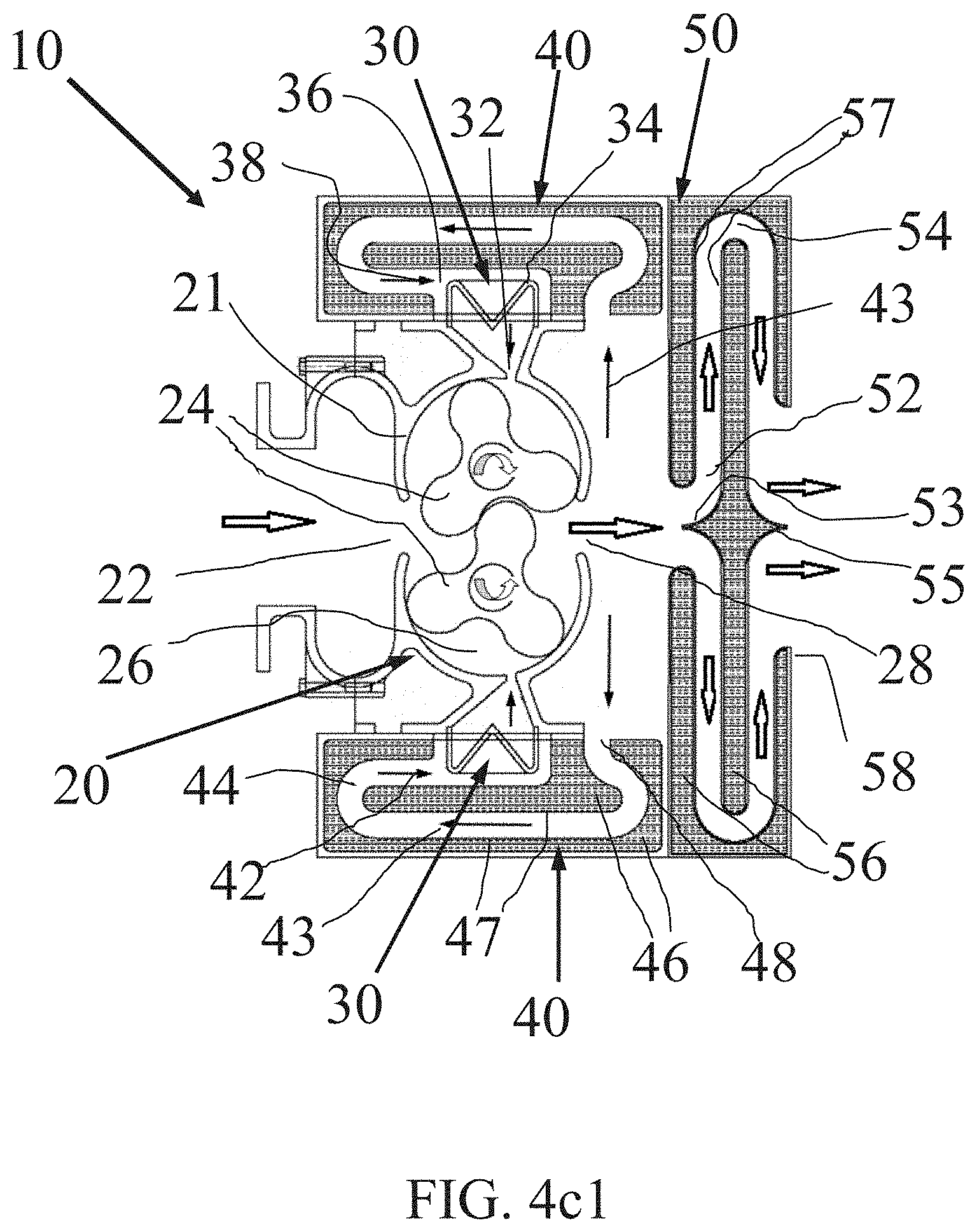
[0020] FIG. 4c1 is a cross-sectional view of the IRPDC with the SPT and the IAS of FIG. 4a.
[0021] FIG. 4c2 is a perspective cross-sectional view of the IAS of the IRPDC with the SPT and the IAS of FIG. 4b, showing exemplary details of perforated plate and sound absorptive materials.
[0022] FIG. 4c3 is a cross-sectional view of an IAS of an IRPDC with an SPT and an IAS according to a second example embodiment of the present invention.
[0023] FIG. 4d is a cross-sectional view of an IRPDC with an SPT and an IAS according to a third example embodiment of the present invention, showing jet IAS and inlet IAS in a pressure mode.
[0024] FIG. 4e is a cross-sectional view of an IRPDC with an SPT and an IAS according to a fourth example embodiment of the present invention, showing jet IAS and discharge IAS in a deep vacuum mode.
[0025] FIG. 5a is a perspective view of an IRPDC with an SPT and an IAS according to a fifth example embodiment of the present invention, additionally including a 4-way valve to provide for operation in either a pressure mode or a vacuum mode in an integrated vacuum and pressure (IVP) arrangement.
[0026] FIG. 5b is a cross-sectional view of the IRPDC with the SPT, the IAS, and the 4-way valve of FIG. 5a, showing operation in the pressure mode.
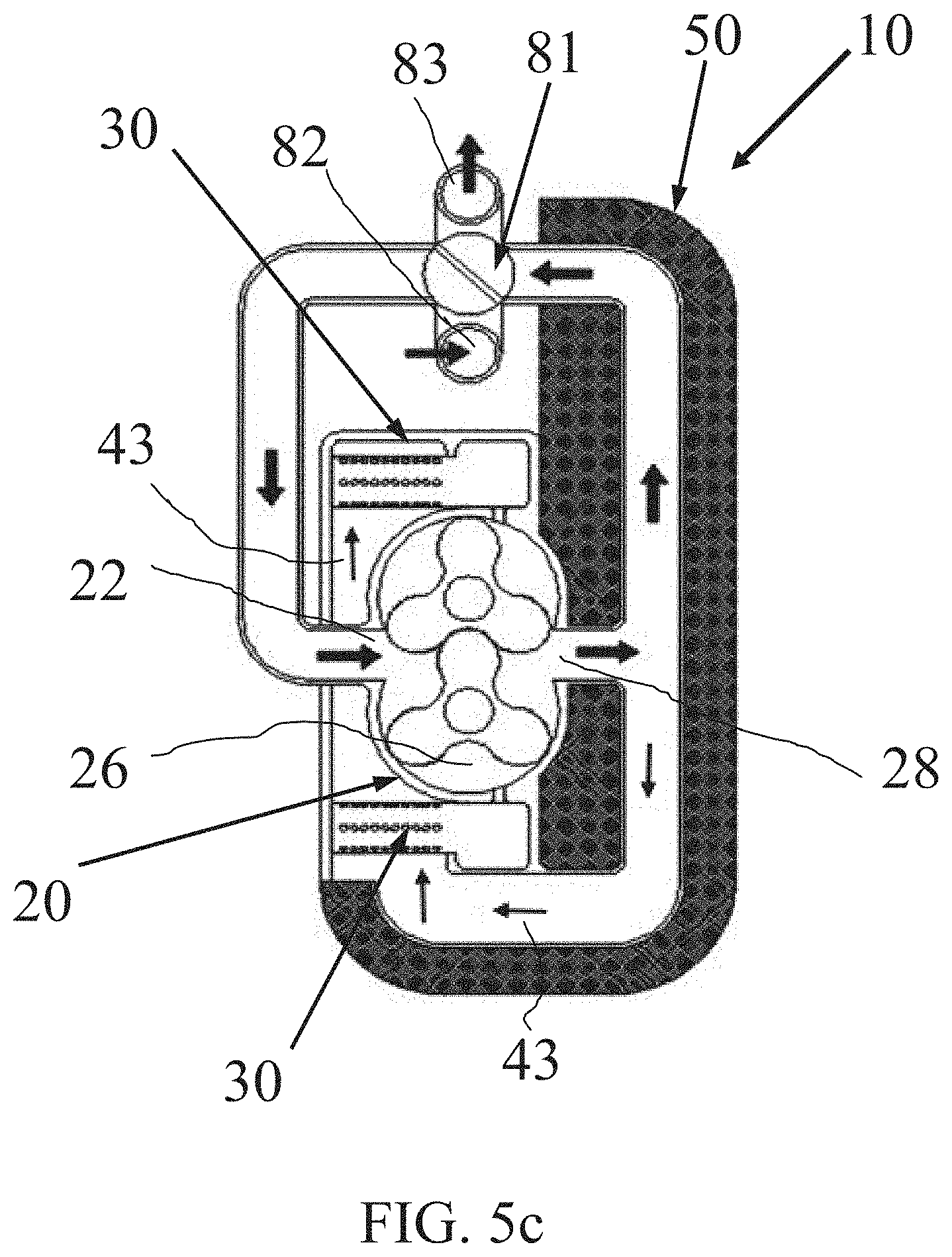
[0027] FIG. 5c shows the IRPDC with the SPT, the IAS, and the 4-way valve of FIG. 5a in operation in the vacuum mode.
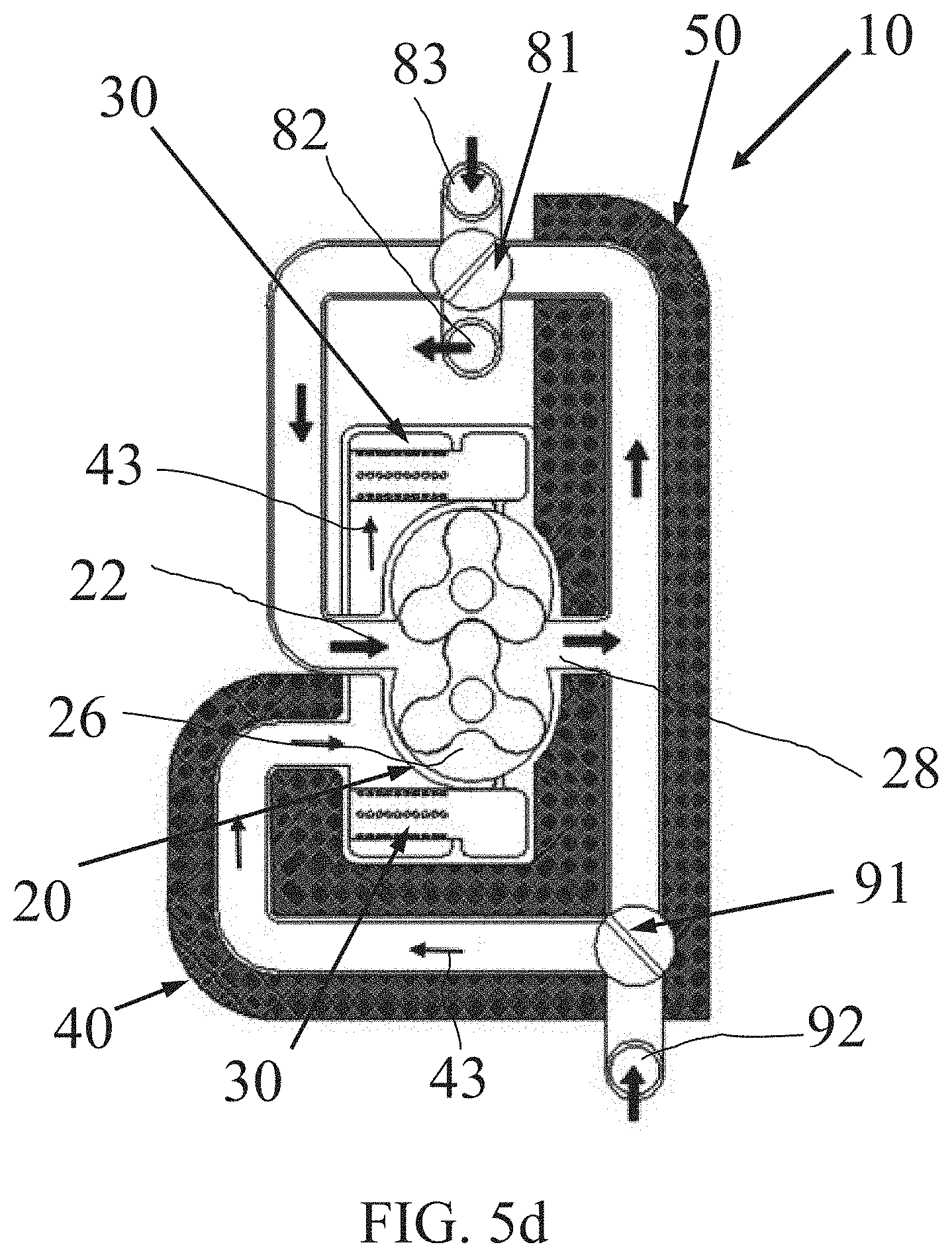
[0028] FIG. 5d is a cross-sectional view of an IRPDC with an SPT, an IAS, and two 4-way valves in an integrated vacuum and pressure (IVP) arrangement according to a sixth example embodiment of the present invention, showing operation in the deep vacuum mode.
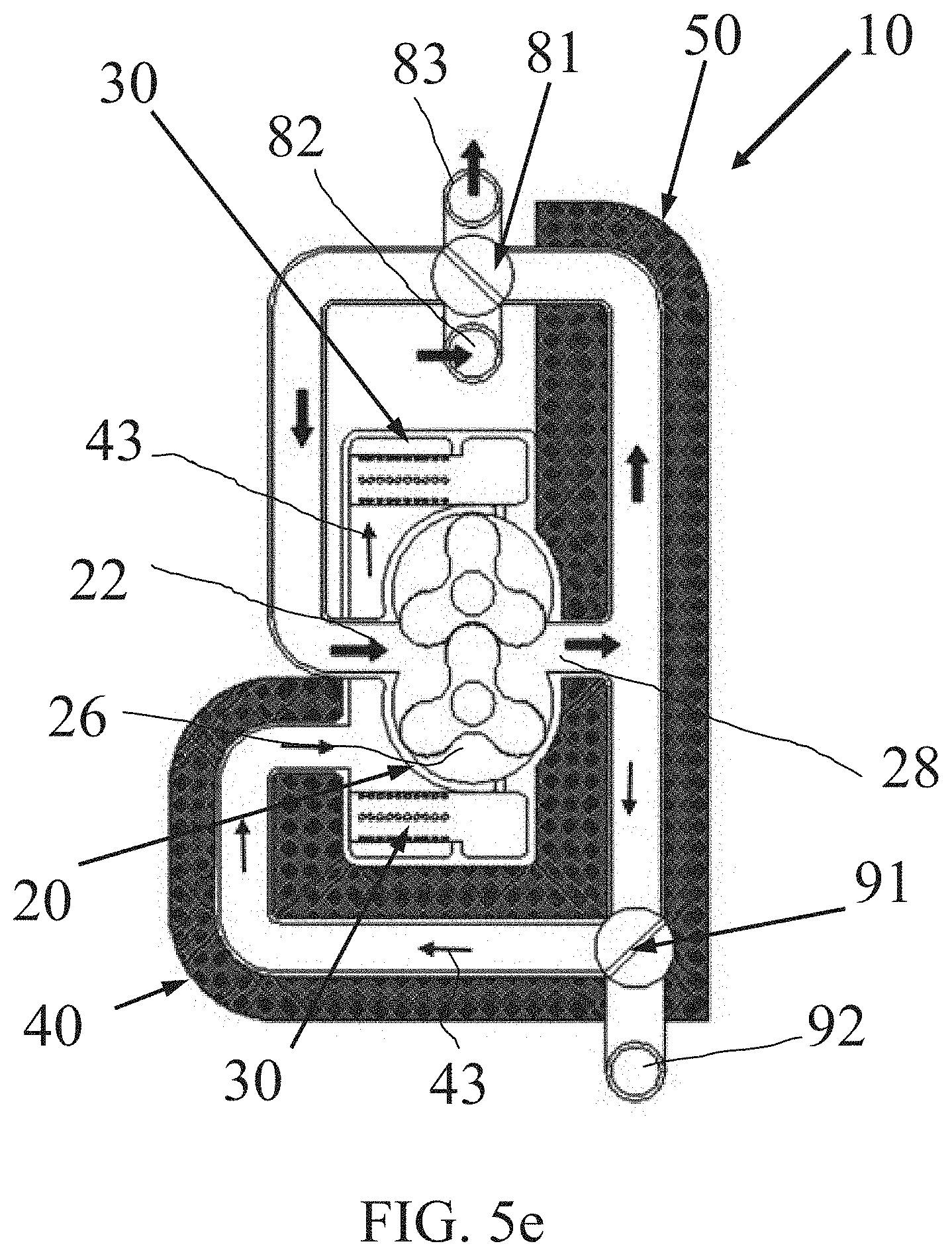
[0029] FIG. 5e shows the IRPDC with the SPT, the IAS, and the two 4-way valves of FIG. 5d in operation in the pressure mode.
DETAILED DESCRIPTION OF EXAMPLE EMBODIMENTS
[0030] Generally described, the present invention relates to integrated rotary positive-displacement compressors (IRPDCs) with shunt pulsation traps (SPTs) and integrated absorptive silencers (IASs) to reduce low-frequency gas pulsations and high-frequency noise while maintaining a smaller size and not suffering back pressure loss. In some embodiments, the SPT is parallel-connected with a cavity of the compressor and is able to control the large-amplitude low-frequency pulses by trapping waves and converting one big low-frequency pulse jet into multiple smaller-frequency jets that generate higher-frequency noises. And the IAS is serially connected with the compressor cavity, absorbing the high-frequency noises plus those generated due to lobe meshing and leftover from the SPT. The SPT and the IAS are combined in a configuration to achieve adequate dampening without suffering noticeable back pressure loss. The IAS can interface directly and seamlessly with a rectangular cross-sectional shape of a compressor core inlet/outlet while folding its flow path in a conforming shape to an exterior shape of the compressor core. Generally, the IAS provides about the same noise-absorptive effectiveness as a conventional silencer by maintaining about the same flow velocity and total area of absorbing surface (perforated surface with absorptive material inside) that the gas-flow passes.
[0031] There are several additional advantages provided by the IRPDCs with the SPTs and the IASs. First of all, added turns to the gas-flow path of the IAS block the direct path of the sound propagation to reduce the noise, the while the effect on back pressure loss is minimum. Secondly, the IAS has a modified cross-sectional shape that eliminates the cross-sectional shape transition from a rectangular to a circular flange in a traditional cylindrical shaped silencer to help reduce the back-pressure loss and material consumption. And thirdly, the IAS provides for a reduced total space (also called installation space) that is occupied.
[0032] Typical embodiments of the IRPDCs with the SPTs and the IASs have three modes of operation: vacuum mode, pressure mode, and deep vacuum mode. The vacuum mode is an application with the inlet port of the compressor core connected to a process while the outlet port of the compressor core is connected to the IAS through the SPT which in turn is open to atmosphere. The pressure mode is an application with the outlet port of the compressor core connected to a process through the SPT while the inlet port of the compressor core is interfaced directly to the IAS which in turn is open to atmosphere. And the deep vacuum mode is the same as the vacuum mode for the inlet and outlet port connections, but it has a 3rd jet port open to atmosphere that allows cool atmospheric air into the compressor cavity through the SPT to extend the pressure ratio range (e.g., from about 2/1 for such two-port applications) up to about 10/1. Additional IASs can be used for jet ports as desired.
[0033] Another embodiment of the invention includes an integrated vacuum and pressure (IVP) feature that provides for dual operation in the vacuum mode or in the pressure mode. IVP embodiments are well-suited for mobile applications where noise, space, and weight are primary requirements. In typical IVP embodiments, the IRPDCs with the SPTs and the IASs additionally include with an integrated 4-way valve for example located in front of the compressor core inlet/outlet to switch the same system between the vacuum mode and pressure mode. Some IVP embodiments, such as a liquid tank hauler that uses vacuum to load and pressure to unload, can include two 4-way valves to operate in the pressure mode or the deep vacuum mode. The second 4-way valve opens or closes a jet flow from atmosphere to help reach deep vacuum or stays for normal pressure/vacuum mode. The jet IAS is included in this case while a discharge IAS and a discharge SPT are optional for IVP embodiments.
[0034] Turning now to the drawings, FIGS. 4a-5e show various integrated rotary positive-displacement compressors (IRPDCs) with shunt pulsation traps (SPTs) and integrated absorptive silencers (IASs) according to various example embodiments of the present invention. Although specific embodiments of the invention are described and illustrated, it should be understood that such embodiments are examples only and merely illustrative of but a small number of the many possible embodiments of the present invention. For example, most of the drawings and description are devoted to IRPDCs representing improvements in a Roots-type RPDC for controlling gas pulsations and noises in an under-compression mode, but the other types of RPDCs (including those identified in FIG. 1) can be adapted to implement the same improvements. In addition to compressors and vacuum pumps, rotary positive-displacement expanders (a variation used to generate shaft power from gas-media pressure drop) are included within the meaning of RPDCs. Also, the invention can be implemented in various embodiments for use with a range of gas media such as vapor-liquid two-phase flow as used in air conditioning or refrigeration.
[0035] FIG. 4a shows a compression cycle of an innovative IRPDC with an SPT combined with an IAS according to various example embodiments of the invention. The SPT is connected in parallel with a cavity/core of the compressor and used to trap and break up the single, big, fast jet (IFF and EW) of the primary low-frequency pulsation into multiple smaller and slower jets that generate higher-frequency noises (see, e.g., FIG. 3b for a Roots compressor). Additional details of conventional RPDCs with SPTs are disclosed in for example U.S. Pat. Nos. 9,140,260; 9,151,292; 9,140,261; 9,243,557; 9,551,342; and 9,732,754, which have been incorporated by reference, and thus such additional details are not repeated herein for brevity and clarity.
[0036] The IRPDCs of the present invention additionally include an IAS that is serially connected with the compressor cavity/core and used to attenuate the secondary pulsations generated due to lobe meshing and the higher-frequency noises induced from the SPT in order to reduce the flow-borne pulsation and noises carried to downstream equipment and/or to the atmosphere. This is in contrast to conventional combination type pulsation dampening and noise attenuation devices (see, e.g., FIG. 2e), which are connected in series with the compressor discharge port (see, e.g., FIG. 2a), and which do no indiscriminate between low-frequency pulsations and high-frequency noises. The IRPDCs improve on this conventional design by combining an IAS with an SPT to separate the main flow (Q) from the primary pulsed flow (IFF) so that only the primary pulsed flow (IFF) will go through the SPT dampener and be attenuated there for the primary low-frequency large-amplitude pulsations, while the secondary pulsations and high-frequency noises are carried with the main flow (Q) to be treated by the serially connected IAS (see FIG. 4a).
[0037] There are several unique features and advantages of the IRPDCs with the parallel SPTs and the IASs of the present invention compared with traditional serially connected single dampeners. First of all, the primary pulsed flow (IFF) is separated out from the main cavity flow (Q) through the parallel SPT dampener so that an effective attenuation on the primary pulsed flow IFF will not create any serial back-pressure for the compressor to overcome, resulting in work saving (see FIG. 3c), hence enhancing both the compressor system efficiency across the whole flow range and the pulsation attenuation effectiveness with a much smaller-sized reactive dampening device (typically, at least 10 times smaller in volume). In a conventional serially connected reactive dampener (see, e.g., FIGS. 2c and 2e), both pulsed flow IFF and main flow Q travel through the dampening device where a better attenuation on pulsed flow IFF comes at the cost of higher compressor back pressure or larger dampener size to accommodate the combined Q and IFF flow. A compromise is often made in order to reduce compressor back pressure by sacrificing the degree of pulsation dampening or by using a very large-volume dampener, resulting in a bulky, heavy, and costly dampener.
[0038] Secondly, by first pre-treating the primary pulsations by the SPT, the left-over secondary pulsations and induced high-frequency noises can be effectively treated by an absorptive-type silencer. This absorptive-type silencer has much-lower back-pressure losses (typically, at least 10 times lower) than the same-sized reactive-type silencer, hence less work is needed (see FIG. 3c). And this absorptive-type silencer can be of a much-smaller size than conventional pulsation-dampening devices.
[0039] Thirdly, the SPT attenuates the primary pulsations much closer to the pulsation source (the compressor core/cavity) than in a conventional serial scheme and enables the use of a much-smaller sized absorptive-type silencer (without creating any serial back pressure), and at least in part because of this the absorptive silencer can be included as an integral part of the casing. As such, the IAS is a specialized and integrated design of a conventional absorptive-type silencer. For example, the absorptive-type silencer can be included as close as possible to the compressor core/cavity, in a conforming shape with its flow channels folded, so that the overall size and footprint of the compressor package is much smaller relative to the prior art. Also, by replacing the traditional flange-connected cylindrical-shaped absorptive dampener (see, e.g., FIG. 2d) with a directly and seamlessly interfaced specialized IAS to the compressor core (see, e.g., FIG. 4b), the back-pressure loss and material consumption are further reduced by eliminating the cross-sectional shape transition from the compressor core's rectangular inlet/outlet (also called the suction/discharge port) to the circular-flanged traditional silencer. Moreover, noise is further reduced due to the added turns in the folded flow passage that blocks the direct path of the sound propagation from the compressor core and due to the elimination of some of the noise radiation surfaces from the naked casing now covered by the IAS. Other features and advantages are further described throughout the specification and drawings.
[0040] Referring specifically to FIG. 4c1, there is shown an IRPDC 10 integrally combined with an SPT 30, a jet IAS 40, and a discharge IAS 50 according to a first example embodiment of the invention. Other embodiments of the IRPDC with the SPT include only the jet IAS 40, only the discharge IAS 50, and/or additionally one or more other IASs.
[0041] The IRPDC 10 of the depicted embodiment is a Roots-type compressor, though other embodiments include other types of IRPDCs (e.g., vacuum pumps and expanders) equipped with the SPT and the IAS, as noted herein. The IRPDC 10 includes a compressor core 20 and two parallel-axis rotors 24, with the compressor core 20 including a casing 21 that defines a compression chamber 26 with an integral suction port 22 and an integral discharge port 28, and with the rotors 24 housed in the compression chamber 26 and configured for propelling gas-flow from the suction port 22 to the discharge port 28.
[0042] The SPT 30 is arranged adjacent to the compressor core 20 and includes a pulsation trap chamber 36, an injection port (trap inlet) 32 branching off from the compression chamber 26 into the pulsation trap chamber 36, a feedback port (trap outlet) 38 communicating with the compressor core outlet 28, and a pulsation dampener 34 housed in the pulsation trap chamber 36 and interfaced with the trap inlet 32. The pulsation dampener 34 can be of a variety of different types, including an M-shaped dampener (as depicted) or other conventional dampeners as have been incorporated by reference. It should be pointed out that the pulsation trap chamber 36 becomes an expansion chamber when the pulsation dampener 34 is absent.
[0043] The jet IAS 40 and the discharge IAS 50 are each integrated into the IRPDC 10 and arranged adjacent to the compressor core 20, with the jet IAS 40 positioned generally opposite the SPT 30. In some embodiments such as that depicted, the jet IAS 40 and the discharge IAS 50 cooperate with the SPT 30 to conform to the shape of and generally surround (e.g., on three sides) the compressor core 20.
[0044] The jet IAS 40 includes an outlet 42 interfacing with the trap outlet 38 and a flow channel 44 leading to an inlet 48 communicating with the compressor core outlet 28. Typically, the flow channel 44 is folded or non-linear, with two (or another number of) turns, with each (or at least one) turn equal to or greater than about 180 degrees. Also, the flow channel 44 is defined by channel walls 47 made of for example conventional perforated plates, with conventional absorptive dampening material 46 surrounding the channel 44 (e.g., sandwiched between the perforated channel walls 47 and a casing of the IAS 40).
[0045] The discharge IAS 50 includes an inlet 52 interfacing with the compressor core outlet 28 including at least one flow channel 54 leading to an outlet 58 for discharging the gas-flow (to atmosphere in vacuum mode). In the depicted embodiment, the IAS 50 includes a flow divider (e.g., with a protruding lip) 53 for splitting the gas-flow into two folded flow channels 54 that each terminate at a flow merger 55 (e.g., arranged symmetrically with the divider 53) before discharging to the outlet 58. Typically, the flow channel 54 on each side is folded or non-linear, with three (or another number of) turns, with two end turns each equal to or greater than about 90 degrees, and with one middle turn equal to or greater than about 180 degrees. The folded flow channels 54 are defined by channel walls 57 made of for example conventional perforated plates, with conventional absorptive dampening material 56 (see, e.g., FIG. 4c2) surrounding the channels 54 (e.g., sandwiched between the perforated walls 57 and a casing of the IAS 50).
[0046] In operation of the IRPDC 10, the rotors 24 propel a main cavity flow (as indicated by the large directional arrows pointing into and out of the compressor cavity) from the suction port 22 to the discharge port 28 and into the discharge IAS 50, while a feedback flow (IFF) 43 (as indicated by the small directional arrows) goes from the compressor core outlet 28 through the jet IAS 40 into the trap outlet 38 into the pulsation trap dampener 34 and converging into the injection port (trap inlet) 32 and releasing into the compression chamber 26. As each rotor lobe tip passes over the trap inlet 32 (see, e.g., the left rotor in FIG. 3b, which shows the SPT wave and flow patterns in more detail and thus illustrates the equivalent wave and flow pattern for FIG. 4c1), a series of compression waves are generated at the trap inlet 32 going into the compression chamber 26, thereby inducing the feedback flow (IFF) 43. Simultaneously, a series of expansion waves are generated at the trap inlet 32, but travelling in a direction opposite to the feedback flow 43, that is, from the trap inlet 32, through the dampener 34 where it is trapped and the induced single-jet IFF is broken into multiple smaller jets that generate high-frequency noises, which radiate into the trap outlet 38. The jet IAS 40 thus intercepts and attenuates the high-frequency noise generated by the SPT 30 before it reaches the IRPDC outlet 28.
[0047] At the same time, the main cavity flow is propelled by the rotors 24 from the suction port 22 to the discharge port 28, generating secondary pulsations from the rotors (e.g., lobes) 24 meshing and inducing wide-band noises. The discharge IAS 50 is used to tackle these secondary pulsations and noises plus what is left from the jet IAS 40 by splitting the main flow into two oppositely traveling branches/channels 54 where the sound absorbing surface area can be maximized to turn flow vibration energy into heat through the absorptive materials 56.
[0048] Referring to FIG. 4c3, a second example embodiment of the invention includes a modified discharge IAS 51 that can be integrated into the IRPDC with the SPT of any of the embodiments disclosed herein. This discharge IAS 51 includes two flow branches/channels that split and meet again, as in the first embodiment, but with different flow channel lengths. For example, the difference between the first flow channel length L1 and the second flow channel length L2 can be about 1/4 wave length so that the noise carried by the two flow channels can be cancelled out at that frequency, further reducing noise.
[0049] When a rotary blower IRPDC 10 equipped with the SPT 30 is combined with any of the IASs 40, 50, and 51 described herein, there is provided a significant reduction in gas pulsation and induced noise at the source and improved compressor design and off-design efficiency without using a traditional serial pulsation dampener and while being light in mass, compact in size, and suitable for high-efficiency variable pressure-ratio applications.
[0050] FIG. 4d shows an IRPDC 10 integrally combined with an SPT 30, a suction IAS 65, and an optional jet IAS 69 according to a third example embodiment of the invention. Other embodiments of the IRPDC with the SPT include only the suction IAS 65, only the optional jet IAS 69, and/or additionally one or more other IASs. The IRPDC 10 is shown operating in pressure mode with the outlet port 28 of the compressor core 20 communicating with a process by flange 68 while the inlet port 22 of the compressor core 20 is interfaced directly to the suction IAS 65 which in turn is open to atmosphere. The SPT 30 functions the same way as in the vacuum mode described above and can still be optionally connected with the jet IAS 69. Feedback flow 43 is also shown for clarity.
[0051] In addition, an inlet dampener 67 can be added between the compressor core inlet 22 and the suction IAS outlet 66, for example as depicted. The inlet dampener 67 is selected and configured to dampen some of the secondary pulsations due to the rotor lobes 24 sudden un-meshing.
[0052] FIG. 4e shows an IRPDC 10 integrally combined with an SPT 30, at least one jet IAS 71, and a discharge IAS 50 according to a fourth example embodiment of the invention. Other embodiments of the IRPDC with the SPT include only the discharge IAS 50, only the jet IAS 71, and/or additionally one or more other IASs. The IRPDC 10 is shown operating in deep vacuum mode and has the same inlet 22 and outlet 28 port connections as the vacuum mode. However, the jet IAS 71 has an inlet 72 that is open to atmosphere that allows cool atmospheric air flow in (as shown by the small directional arrows) through the SPT 30 into the compression chamber 26 of the compressor core 20 to extend the pressure ratio range (e.g., from about 2/1 as typical for the above defined 2-port applications to about 10/1 in this mode). The jet IAS 71 is separated from the discharge port 28 and directly communicates with cool atmospheric air at the inlet 72 without going through the discharge IAS 50 as in vacuum mode.
[0053] Additional embodiments of the invention provide integrated vacuum and pressure operation, with this sometimes referred to herein as IVP technology. IVP is ideal for mobile applications (e.g., liquid tank haulers) and other applications where noise, space and weight are primary requirements.
[0054] FIGS. 5a-5c show an IRPDC 10 integrally combined with an SPT 30, a discharge IAS 50, and a 4-way flow-direction valve 81 according to a fifth example embodiment of the invention. Other embodiments of the IRPDC with the SPT include 4-way-valve 75 with other configurations of IASs. This embodiment combines the vacuum mode with the pressure mode as one dual-purpose (pressure and vacuum) machine with the integrated 4-way valve 81 for switching between the vacuum mode (FIG. 5b) and the pressure mode (FIG. 5c).
[0055] FIG. 5b shows the 4-way valve 81 located in front of the compressor core 20 and set for vacuum mode when port 83 connecting to a system is connected with the compressor core inlet 22, while port 82 connecting to atmosphere is connected with the compressor core outlet 28. On the other hand, FIG. 5c shows the 4-way valve 81 valve position for pressure mode, but the same port 83 is now connecting with the compressor core outlet 28 through the SPT 30, while the same port 82 is now acting as the inlet port connecting with the compressor core inlet 22. It should be noted that the flows in and out of the compressor core 20 always stay the same under vacuum and pressure mode, and so do the feedback flows 43 (indicated by the small directional arrows) that go from the compressor core outlet 28 through part of the discharge IAS 50 (suction IAS is optional, not shown here) into the SPT 30 and into the compression chamber 26. During vacuum mode (FIG. 5b), the inlet flow from the connected system is sucked through port 83 as directed by 4-way valve 81 towards the compressor core inlet 22 (indicated by the large directional arrows) while the main discharge flow travels through the discharge IAS 50 and is guided by the 4-way valve 81 to discharge at port 82.
[0056] FIGS. 5d and 5e show an IRPDC 10 integrally combined with an SPT 30, a jet IAS 40, a discharge IAS 50, a 4-way flow-direction valve 81, and a 4-way jet valve 91 according to a sixth example embodiment of the invention. This embodiment is similar to that of the fifth embodiment, for example it include the same IVP technology, and additionally includes the jet valve 91 located at the jet port 92 in FIG. 5d is set for deep vacuum mode when port 92 is connecting the cavity 26 of the compressor core 20 with atmosphere except with the SPT 30 and the jet IAS 40 in-between. This embodiment can be particularly suitable for use in mobile applications such as liquid tank haulers that use vacuum to load and pressure to unload.
[0057] During the deep vacuum mode shown in FIG. 5d, the inlet flow from the connected system is sucked through port 83, as directed by 4-way flow-direction valve 81, towards the compressor core inlet 22 (as shown by the large arrows) while the main discharge flow travels form the core outlet 28 through the discharge IAS 50 and is guided by the 4-way valve 81 to discharge at port 82. However, the feedback flow 43 (as indicated by the small arrows) goes from the 4-way jet valve 91, which is open to atmosphere now, through the jet IAS 40 into the SPT 30 and into the compression chamber 26 for additional cooling to reach deep vacuum.
[0058] When the 4-way jet valve 91 is set closed to atmosphere, as shown in FIG. 5e, the compressor is back to the pressure and vacuum mode (as described above with respect to FIGS. 5b-5c). The two 4-way valves 81 and 91 are designed so that when the 4-way jet valve 91 is open to atmosphere, the 4-way flow-direction valve 81 is in vacuum mode, and when the 4-way jet valve 91 is closed to atmosphere, the 4-way flow-direction valve 81 is in pressure mode. An interlocking and linkage mechanism can be provided for this functionality.
[0059] In these and other embodiments of the invention, a single casing/housing can be formed for the IRPDC including the SPT and the IAS, for example by casting two cross-sectional halves each including halve of the IRPDC, the SPT, and the IAS. Also, the IAS flow channels can be generally rectangular and configured (e.g., sized and shaped) to conform to the outlet of the compressor core. Further, the folds or turns in the IAS flow channels can have a serpentine configuration with at least one 180-degree bend so that the channel is folded back over itself.
[0060] Accordingly, various embodiments of the present invention provide various advantages over the prior art. For example, an IRPDC with an SPT and an IAS can provide for trapping and attenuating not only primary pulsations but also the secondary induced noises as well at the source. Also, an IRPDC with an SPT and an IAS can provide for improving compressor system efficiency by eliminating the back pressure loss resulted from the serially connected traditional dampener at inlet or discharge. In addition, an IRPDC with an SPT and an IAS can provide for a lighter weight and more-compact size by eliminating the serially connected traditional dampener at inlet or discharge. Furthermore, an IRPDC with an SPT and an IAS for trapping and attenuating not only primary pulsations but the secondary induced noises as well at source, in a wide range of pressure ratios and/or in a wide range of speeds and cavity passing frequency, without using a traditional serial dampener.
[0061] It is to be understood that this invention is not limited to the specific devices, methods, conditions, or parameters of the example embodiments described and/or shown herein, and that the terminology used herein is for the purpose of describing particular embodiments by way of example only. Thus, the terminology is intended to be broadly construed and is not intended to be unnecessarily limiting of the claimed invention. For example, as used in the specification including the appended claims, the singular forms "a," "an," and "the" include the plural, the term "or" means "and/or," and reference to a particular numerical value includes at least that particular value, unless the context clearly dictates otherwise. In addition, any methods described herein are not intended to be limited to the sequence of steps described but can be carried out in other sequences, unless expressly stated otherwise herein.
[0062] While the claimed invention has been shown and described in example forms, it will be apparent to those skilled in the art that many modifications, additions, and deletions can be made therein without departing from the spirit and scope of the invention as defined by the following claims.
* * * * *
D00000
D00001
D00002
D00003
D00004
D00005
D00006
D00007
D00008
D00009
D00010
D00011
D00012
D00013
XML
uspto.report is an independent third-party trademark research tool that is not affiliated, endorsed, or sponsored by the United States Patent and Trademark Office (USPTO) or any other governmental organization. The information provided by uspto.report is based on publicly available data at the time of writing and is intended for informational purposes only.
While we strive to provide accurate and up-to-date information, we do not guarantee the accuracy, completeness, reliability, or suitability of the information displayed on this site. The use of this site is at your own risk. Any reliance you place on such information is therefore strictly at your own risk.
All official trademark data, including owner information, should be verified by visiting the official USPTO website at www.uspto.gov. This site is not intended to replace professional legal advice and should not be used as a substitute for consulting with a legal professional who is knowledgeable about trademark law.