Additively Manufactured Thermally Insulating Structure
Butcher; Evan ; et al.
U.S. patent application number 16/152848 was filed with the patent office on 2020-04-09 for additively manufactured thermally insulating structure. The applicant listed for this patent is United Technologies Corporation. Invention is credited to Lawrence Binek, Jesse R. Boyer, Evan Butcher, Bryan G. Dods, Vijay Narayan Jagdale, Om P. Sharma.
| Application Number | 20200109668 16/152848 |
| Document ID | / |
| Family ID | 68382108 |
| Filed Date | 2020-04-09 |


| United States Patent Application | 20200109668 |
| Kind Code | A1 |
| Butcher; Evan ; et al. | April 9, 2020 |
ADDITIVELY MANUFACTURED THERMALLY INSULATING STRUCTURE
Abstract
An additively manufactured thermally insulating structure comprising a base layer and a fire-resistant layer adjacent to the base layer that forms an air gap therebetween. A method for assembling a miniature gas turbine engine includes additively manufacturing an additively manufactured thermally insulating structure onto a static structure of the miniature gas turbine engine.
| Inventors: | Butcher; Evan; (Manchester, CT) ; Boyer; Jesse R.; (Middletown, CT) ; Sharma; Om P.; (South Windsor, CT) ; Binek; Lawrence; (Glastonbury, CT) ; Dods; Bryan G.; (Greer, SC) ; Jagdale; Vijay Narayan; (South Windsor, CT) | ||||||||||
| Applicant: |
|
||||||||||
|---|---|---|---|---|---|---|---|---|---|---|---|
| Family ID: | 68382108 | ||||||||||
| Appl. No.: | 16/152848 | ||||||||||
| Filed: | October 5, 2018 |
| Current U.S. Class: | 1/1 |
| Current CPC Class: | B33Y 80/00 20141201; F05D 2230/31 20130101; F05D 2300/502 20130101; Y02T 50/60 20130101; B33Y 10/00 20141201; F05D 2220/32 20130101; F01D 25/145 20130101; F02C 7/04 20130101; F05D 2240/14 20130101; F05D 2250/82 20130101; F02C 7/25 20130101; B22F 3/1055 20130101 |
| International Class: | F02C 7/25 20060101 F02C007/25; B33Y 10/00 20060101 B33Y010/00; B33Y 80/00 20060101 B33Y080/00; F02C 7/04 20060101 F02C007/04 |
Claims
1. An additively manufactured thermally insulating structure, comprising: a base layer; and a fire-resistant layer adjacent to the base layer that forms an air gap therebetween.
2. The additively manufactured thermally insulating structure as recited in claim 1, wherein the base layer forms a static structure of a gas turbine engine.
3. The additively manufactured thermally insulating structure as recited in claim 1, wherein the base layer is 0.1-0.2 inches (about 2.5-5 mm) thick and the fire-resistant layer is 0.1-0.2 inches (about 2.5-5 mm) thick.
4. The additively manufactured thermally insulating structure as recited in claim 1, wherein the air gap is 0.25-0.5-inch thick (about 6-13 mm).
5. The additively manufactured thermally insulating structure as recited in claim 1, further comprising a lattice structure within the air gap.
6. The additively manufactured thermally insulating structure as recited in claim 1, further comprising a duct through the air gap.
7. The additively manufactured thermally insulating structure as recited in claim 6, wherein the duct comprises at least one intake and at least one exhaust.
8. A miniature gas turbine engine, comprising: a static structure; and an additively manufactured fire-resistant layer additively manufactured to the static structure to form an air gap therebetween.
9. The miniature gas turbine engine as recited in claim 8, wherein the static structure comprises at least one of a forward housing, a combustor housing, and an exhaust pipe.
10. The miniature gas turbine engine as recited in claim 8, wherein the fire-resistant layer adjacent forms a pattern which facilitates fire resistance.
11. The miniature gas turbine engine as recited in claim 8, wherein the fire-resistant layer comprises at least one intake and at least one exhaust.
12. The miniature gas turbine engine as recited in claim 8, wherein the fire-resistant layer comprises an airflow path.
13. The miniature gas turbine engine as recited in claim 8, wherein the fire-resistant layer comprises an air gap with a lattice structure.
14. A method for assembling a gas turbine engine, comprising: additively manufacturing a base layer; and additively manufacturing a fire-resistant layer adjacent to the base layer to form an air gap therebetween.
15. The method as recited in claim 14, wherein additively manufacturing the base layer comprises additively manufacturing a static structure of the gas turbine engine.
16. The method as recited in claim 15, wherein additively manufacturing the base layer comprises additively manufacturing at least one of a forward housing, a combustor housing, and an exhaust pipe.
16. The method as recited in claim 14, wherein additively manufacturing the fire-resistant layer adjacent to the base layer forms an additively manufactured thermally insulating structure.
17. The method as recited in claim 16, further comprising assembling the additively manufactured thermally insulating structure onto a static structure of a gas turbine engine.
18. The method as recited in claim 14, further comprising additively manufacturing a duct into the air gap.
19. The method as recited in claim 14, further comprising additively manufacturing a lattice structure into the air gap.
20. The method as recited in claim 14, wherein the additively manufacturing a fire-resistant layer forms a pattern on an outer surface.
Description
BACKGROUND
[0001] The present disclosure relates to additive manufacturing and, more particularly, to an additively manufactured thermally insulating structure for a miniature gas turbine or turbojet engines.
[0002] Miniature gas turbine or turbojet engines that are typically 1000 pound-force (lbf) thrust and smaller, are often utilized in attritable or expendable applications such as reconnaissance drones, cruise missiles, decoys, and other applications, including air-launched and ground-launched weapon systems. The use of such single use gas turbine engines greatly extends the range of the air vehicle in comparison to the more conventional solid fuel rocket engine; however, such engines need to be manufactured relatively inexpensively yet provide a high degree of reliability and efficiency.
[0003] The miniature gas turbine is thermally shielded from the vehicle during operation to provide thermal isolation and/or for fire-retardant purposes. A thermal blanket is wrapped around engine components to provide the shielding after assembly of the engine and retained thereto with band clamps. The thermal blanket is typically specialized and requires labor-intensive construction of a combination of fabric, composite, and metallic material layers, which form a compliant structure. Although effective, such blankets are relatively expensive and time consuming to fabricate and install.
SUMMARY
[0004] An additively manufactured thermally insulating structure according to one disclosed non-limiting embodiment of the present disclosure includes a base layer; and a fire-resistant layer adjacent to the base layer that forms an air gap therebetween.
[0005] A further embodiment of any of the foregoing embodiments of the present disclosure includes that the base layer forms a static structure of a gas turbine engine.
[0006] A further embodiment of any of the foregoing embodiments of the present disclosure includes that the base layer is 0.1-0.2 inches (about 2.5-5 mm) thick and the fire-resistant layer is 0.1-0.2 inches (about 2.5-5 mm) thick.
[0007] A further embodiment of any of the foregoing embodiments of the present disclosure includes that the air gap is 0.25-0.5-inch thick (about 6-13 mm).
[0008] A further embodiment of any of the foregoing embodiments of the present disclosure includes a lattice structure within the air gap.
[0009] A further embodiment of any of the foregoing embodiments of the present disclosure includes a duct through the air gap.
[0010] A further embodiment of any of the foregoing embodiments of the present disclosure includes that the duct comprises at least one intake and at least one exhaust.
[0011] A miniature gas turbine engine according to one disclosed non-limiting embodiment of the present disclosure includes a static structure; and an additively manufactured fire-resistant layer additively manufactured to the static structure to form an air gap therebetween.
[0012] A further embodiment of any of the foregoing embodiments of the present disclosure includes that the static structure comprises at least one of a forward housing, a combustor housing, and an exhaust pipe.
[0013] A further embodiment of any of the foregoing embodiments of the present disclosure includes that the fire-resistant layer adjacent forms a pattern which facilitates fire resistance.
[0014] A further embodiment of any of the foregoing embodiments of the present disclosure includes that the fire-resistant layer comprises at least one intake and at least one exhaust.
[0015] A further embodiment of any of the foregoing embodiments of the present disclosure includes that the fire-resistant layer comprises an airflow path.
[0016] A further embodiment of any of the foregoing embodiments of the present disclosure includes that the fire-resistant layer comprises an air gap with a lattice structure.
[0017] A method for assembling a gas turbine engine according to one disclosed non-limiting embodiment of the present disclosure includes additively manufacturing a base layer; and additively manufacturing a fire-resistant layer adjacent to the base layer to form an air gap therebetween.
[0018] A further embodiment of any of the foregoing embodiments of the present disclosure includes that additively manufacturing the base layer comprises additively manufacturing a static structure of the gas turbine engine.
[0019] A further embodiment of any of the foregoing embodiments of the present disclosure includes that additively manufacturing the base layer comprises additively manufacturing at least one of a forward housing, a combustor housing, and an exhaust pipe.
[0020] A further embodiment of any of the foregoing embodiments of the present disclosure includes that additively manufacturing the fire-resistant layer adjacent to the base layer forms an additively manufactured thermally insulating structure.
[0021] A further embodiment of any of the foregoing embodiments of the present disclosure includes assembling the additively manufactured thermally insulating structure onto a static structure of a gas turbine engine.
[0022] A further embodiment of any of the foregoing embodiments of the present disclosure includes additively manufacturing a duct into the air gap.
[0023] A further embodiment of any of the foregoing embodiments of the present disclosure includes additively manufacturing a lattice structure into the air gap.
[0024] A further embodiment of any of the foregoing embodiments of the present disclosure includes that the additively manufacturing a fire-resistant layer forms a pattern on an outer surface.
[0025] The foregoing features and elements may be combined in various combinations without exclusivity, unless expressly indicated otherwise. These features and elements as well as the operation thereof will become more apparent in light of the following description and the accompanying drawings. It should be understood, however, the following description and drawings are intended to be exemplary in nature and non-limiting.
BRIEF DESCRIPTION OF THE DRAWINGS
[0026] Various features will become apparent to those skilled in the art from the following detailed description of the disclosed non-limiting embodiments. The drawings that accompany the detailed description can be briefly described as follows:
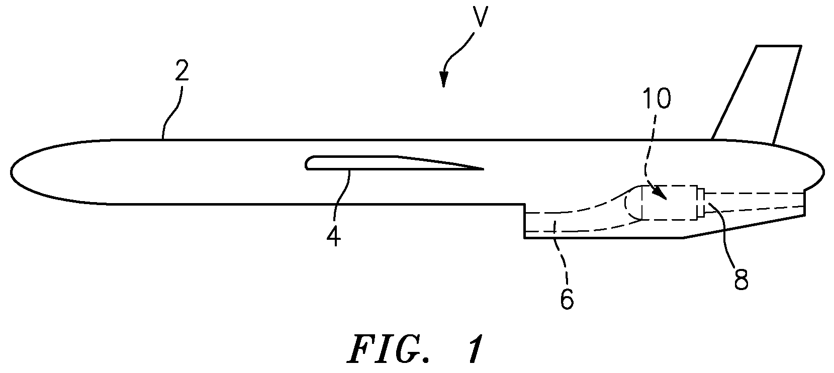
[0027] FIG. 1 is a general perspective view an exemplary vehicle embodiment for use with a miniature gas turbine engine.
[0028] FIG. 2 is a schematic view of an exemplary miniature gas turbine engine according to one disclosed non-limiting embodiment.
[0029] FIG. 3 is an exploded view of the miniature gas turbine engine.
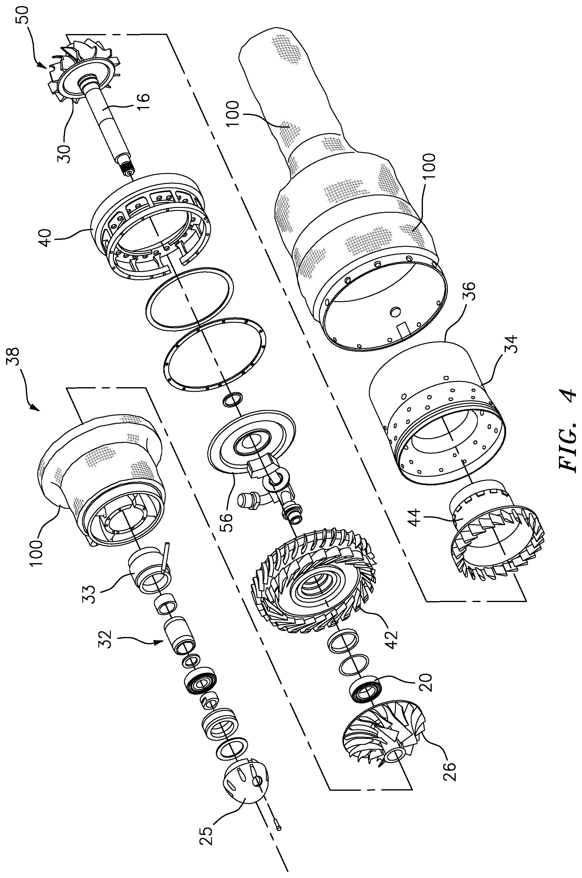
[0030] FIG. 4 is an exploded view of the miniature gas turbine engine.
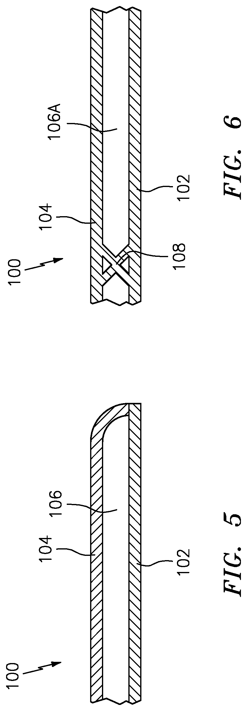
[0031] FIG. 5 is an expanded view of an additively manufactured thermally insulating structure for a miniature gas turbine engine.
[0032] FIG. 6 is a sectional view of the additively manufactured thermally insulating structure according to one disclosed non-limiting embodiment.
[0033] FIG. 7 is a sectional view of the additively manufactured thermally insulating structure according to another disclosed non-limiting embodiment.
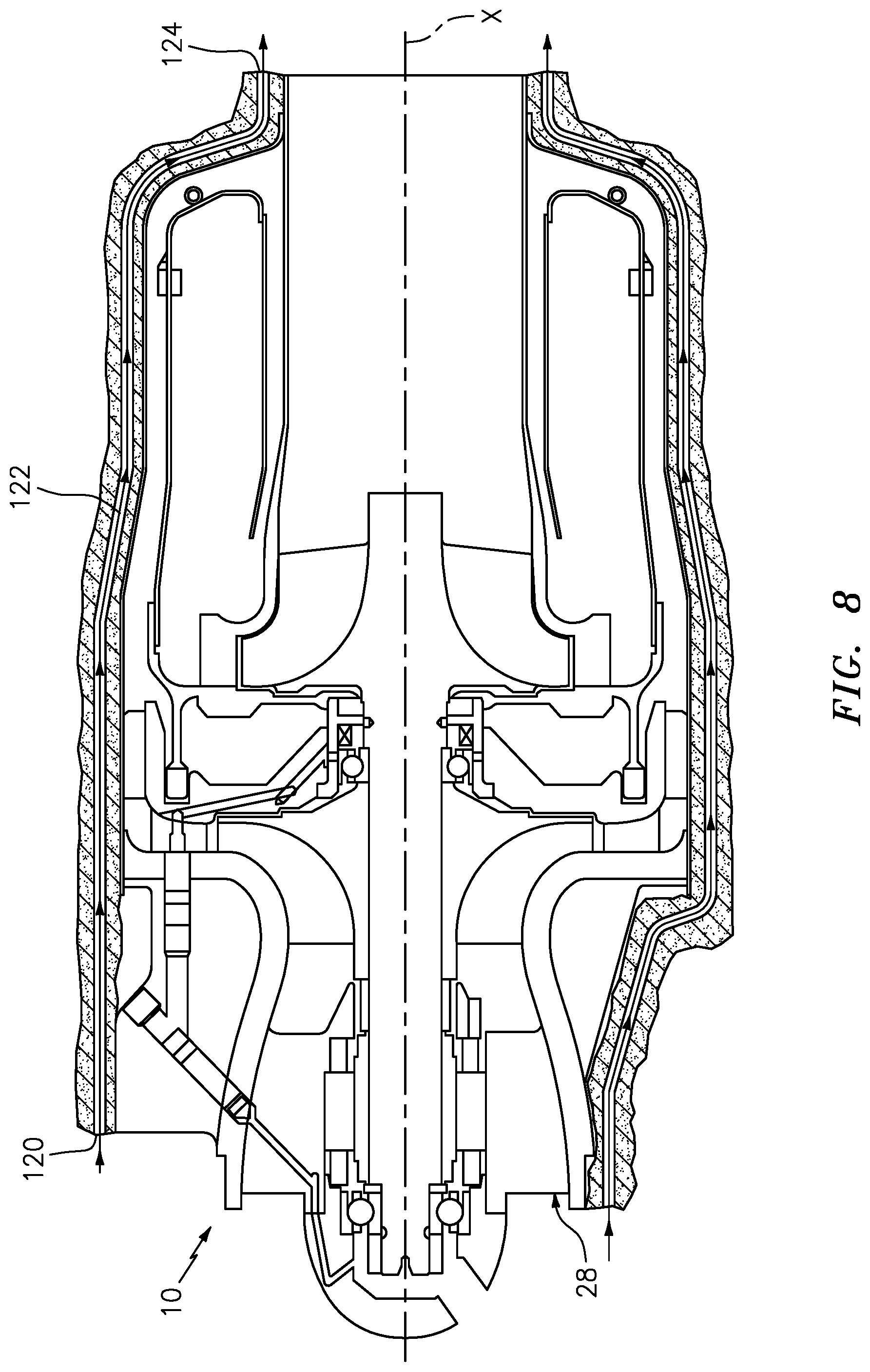
[0034] FIG. 8 is a longitudinal sectional view of the additively manufactured thermally insulating structure with an active cooling flow path according to another disclosed non-limiting embodiment.
[0035] FIG. 9 is a front view of the additively manufactured thermally insulating structure with a multiple of intakes to the active cooling flow of FIG. 8.
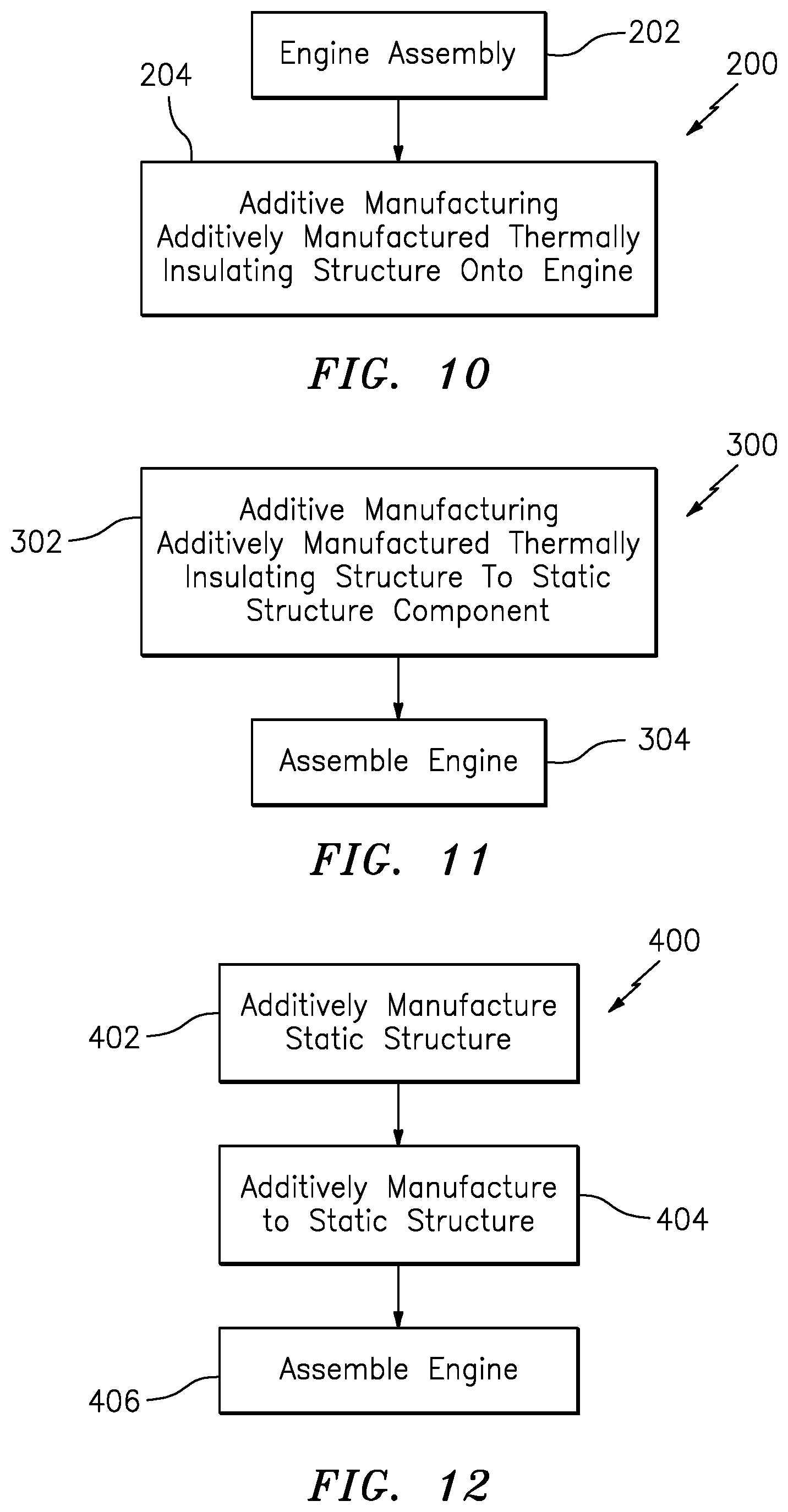
[0036] FIG. 10 is a flow chart illustrating a method to install the additively manufactured thermally insulating structure onto a miniature gas turbine engine according to one disclosed non-limiting embodiment.
[0037] FIG. 11 is a flow chart illustrating a method to install the additively manufactured thermally insulating structure onto a miniature gas turbine engine according to one disclosed non-limiting embodiment.
[0038] FIG. 12 is a flow chart illustrating a method to incorporate the additively manufactured thermally insulating structure into a miniature gas turbine engine according to one disclosed non-limiting embodiment.
DETAILED DESCRIPTION
[0039] FIG. 1 illustrates a general schematic view of an air vehicle V including a miniature gas turbine engine 10. The air vehicle V may include a body 2 and one or more aerodynamic surfaces 4. The miniature gas turbine engine 10 is coupled to, or contained within, the body 2. An intake 6 of the air vehicle V provides air to the miniature gas turbine engine 10 and an exhaust 8 directs the thrust therefrom.
[0040] With reference to FIG. 2, the miniature gas turbine engine 10 generally includes a housing 14, a rotor shaft 16 rotationally mounted to a forward bearing 18 and an aft bearing 20, a combustion system 21, and an exhaust pipe 22. The rotor shaft 16 rotates about a longitudinal axis X. In the illustrated rotor configuration, a rotor 24 includes compressor blades 26 facing forward toward an inlet 28 and turbine blades 30 facing rearward toward the exhaust pipe 22 to define a turbine wheel on the rotor shaft 16. The rotor shaft 16 is received in the bearings 18, 20, and is coupled to a fuel pump 32 to provide fuel to an annular combustor liner 34 through a fuel manifold 36. A permanent magnet generator 33 is mounted to the rotor shaft 16 to generate electrical power for the engine 10 and other accessories.
[0041] With reference also to FIG. 3, a static structure 38 of the engine 10 generally includes the forward housing 14, the forward cover 25, a nozzle plate 40, a diffuser 42, a turbine nozzle 44, a combustor liner 46, a combustor housing 48 and the exhaust pipe 22 (FIG. 3). The forward cover 25 and the diffuser 42 support a rotational system 50 that includes the rotor shaft 16 and rotational components mounted for rotation therewith. The forward cover 25 supports the forward bearing 18 and the diffuser 42 supports the aft bearing 20. The static structure 38 is typically manufactured of a metal alloy and may be assembled together by one or more relatively low-cost fastening techniques such as threaded fasteners, welding, v-band clamps, rivets, or the like.
[0042] With reference to FIG. 4, an additively manufactured thermally insulating structure 100 at least partially surrounds, or forms a portion of, the static structure 38. The additively manufactured thermally insulating structure 100 may be additively manufactured integral with the static structure 38 or alternatively separately for later application to the engine 10 in a manner similar to application of a conventional blanket. That is, the additively manufactured thermally insulating structure 100 may be directly additively manufactured into the engine 10. Although the additively manufactured thermally insulating structure 100 is used for the miniature gas turbine engine 10 in the disclosed embodiment, various other applications may benefit from the additively manufactured thermally insulating structure 100.
[0043] With reference to FIG. 5, the additively manufactured thermally insulating structure 100 according to one embodiment includes a base layer 102 and a fire-resistant layer 104 that forms an air gap 106 therebetween. The base layer 102 forms the static structure 38 of the engine 10 and the fire-resistant layer 104 is spaced therefrom. That is, the base layer 102 may be that which forms the static structure 38 such that the fire-resistant layer 104 that forms the air gap 106 therebetween is integrated therewith. Alloys such as 625 Alloy, 718 Alloy, 230 Alloy, stainless steel, tool steel, cobalt chrome, titanium, nickel, aluminum and others may have specific benefit for environments typically encountered by aerospace and gas turbine engine components such as the base layer 102 and the fire-resistant layer 104. In one example, the base layer 102 is about 0.1-0.2 inches (about 2.5-5 mm) thick, the fire-resistant layer 104 are about 0.1-0.2 inches (about 2.5-5 mm) thick with an about 0.25-0.5-inch thick (about 6-13 mm) air gap 106. The base layer 102 and the fire-resistant layer 104 may be additively manufactured of the same or dissimilar material. The fire-resistant layer 104 may be additively manufacturing to forms a pattern 114, e.g., a waffle pattern, on an outer surface thereof to facilitate the fire resistance.
[0044] With reference to FIG. 6, in another disclosed non-limiting embodiment, the air gap 106 includes a lattice structure 108. In examples, the lattice structure 108 forms numerous contiguous "X" shapes, while other examples may utilize other matrix shapes such as triangular shapes. These various matrix shapes provide support between the base layer 102 and the fire-resistant layer 104 yet maintains the air gap 106A. Alternatively, the air gap 106b could be an monolithic material that has a low thermal conductivity to provide insulating characteristics.
[0045] With reference to FIG. 7, in another disclosed non-limiting embodiment, the air gap 106B forms an intake 120, a duct 122, and an exhaust 124 to form a bypass duct 136 such that an airflow is passed through the additively manufactured thermally insulating structure 100 to provide active cooling via airflow (FIG. 8). The bypass duct 136 may be discrete linear ducts, an integral duct with multiple intakes 120 (FIG. 9) and exhausts 124, or other combinations either with, or without, the lattice structure 108 (FIG. 7).
[0046] With reference to FIG. 10, a method 200 to install the additively manufactured thermally insulating structure 100 initially includes assembly of the engine 10 (202). Next, the additively manufactured thermally insulating structure 100 is additively manufactured onto the static structure 38 once the engine 10 is assembled (204). The additive manufacturing process includes, but is not limited to, Fused deposition modeling (FDM), Stereolithography (SLA), processes using a layer-by-layer UV curing, Selective Laser Sintering (SLS), Electron Beam Sintering (EBS), Electron Beam Melting (EBM), Electron Beam Powder Bed Fusion (EB-PBF), Electron Beam Powder Wire (EBW), Laser Engineered Net Shaping (LENS), Laser Net Shape Manufacturing (LNSM), Direct Metal Deposition (DMD), and Laser Powder Bed Fusion (L-PBF). The additive manufacturing process sequentially builds-up layers of atomized alloy and/or ceramic powder material that include but are not limited to, 625 Alloy, 718 Alloy, 230 Alloy, stainless steel, tool steel, cobalt chrome, titanium, nickel, aluminum, acrylonitrile butadiene styrene (ABS), nylon, polylactic acid (PLA), polyurethane, urethane, silicone, epoxy, photopolymers that provide rubber-like flexibility, and others in atomized powder material form. That is, the engine 10 may be loaded into the additive manufacturing system and the additively manufactured thermally insulating structure 100 is additively manufactured thereon.
[0047] With reference to FIG. 11, a method 300 to install the additively manufactured thermally insulating structure 100 according to another disclosed non-limiting embodiment initially includes additively manufacturing the additively manufactured thermally insulating structure 100 onto the static structure 38 (302). For example, the forward housing 14, the combustor housing 48 and the exhaust pipe 22 are individually loaded into the additive manufacturing system and the additively manufactured thermally insulating structure 100 is additively manufactured thereon. Next, the engine 10 is assembled (304) from the components that have the additively manufactured thermally insulating structure 100 additively manufactured thereon. The additively manufactured thermally insulating structure is thus integrated onto each component individually to facilitate assembly and disassembly.
[0048] With reference to FIG. 12, a method 400 to install the additively manufactured thermally insulating structure 100 according to another disclosed non-limiting embodiment initially includes additively manufacturing the static structure 38 (402) as the base layer 102. For example, the forward housing 14, the combustor housing 48 and the exhaust pipe 22 are additively manufactured and forms the base layer 102. Next, the fire-resistant layer 104 is additively manufactured to the base layer 102 (404) to form the air gap 106 therebetween to form static structure 38 components that have the additively manufactured thermally insulating structure 100 integral therewith.
[0049] Next, the engine 10 is assembled (406) from the components that have the additively manufactured thermally insulating structure 100 additively manufactured thereon. The additively manufactured thermally insulating structure is thus integrated onto each component individually to facilitate assembly and disassembly.
[0050] The additively manufactured thermally insulating structure increases the attritable or expendable propulsion systems by, for example, integration of complex performance-enhancing features, lowering production costs, and reducing time to delivery; that are typically prohibitive when leveraging conventional manufacturing techniques.
[0051] Although the different non-limiting embodiments have specific illustrated components, the embodiments of this invention are not limited to those particular combinations. It is possible to use some of the components or features from any of the non-limiting embodiments in combination with features or components from any of the other non-limiting embodiments.
[0052] It should be appreciated that like reference numerals identify corresponding or similar elements throughout the several drawings. It should also be appreciated that although a particular component arrangement is disclosed in the illustrated embodiment, other arrangements will benefit herefrom.
[0053] Although particular step sequences are shown, described, and claimed, it should be understood that steps may be performed in any order, separated or combined unless otherwise indicated and will still benefit from the present disclosure.
[0054] The foregoing description is exemplary rather than defined by the limitations within. Various non-limiting embodiments are disclosed herein, however, one of ordinary skill in the art would recognize that various modifications and variations in light of the above teachings will fall within the scope of the appended claims. It is therefore to be understood that within the scope of the appended claims, the disclosure may be practiced other than as specifically described. For that reason the appended claims should be studied to determine true scope and content.
* * * * *
D00000
D00001
D00002
D00003
D00004
D00005
D00006
D00007
D00008
XML
uspto.report is an independent third-party trademark research tool that is not affiliated, endorsed, or sponsored by the United States Patent and Trademark Office (USPTO) or any other governmental organization. The information provided by uspto.report is based on publicly available data at the time of writing and is intended for informational purposes only.
While we strive to provide accurate and up-to-date information, we do not guarantee the accuracy, completeness, reliability, or suitability of the information displayed on this site. The use of this site is at your own risk. Any reliance you place on such information is therefore strictly at your own risk.
All official trademark data, including owner information, should be verified by visiting the official USPTO website at www.uspto.gov. This site is not intended to replace professional legal advice and should not be used as a substitute for consulting with a legal professional who is knowledgeable about trademark law.