Systems, Methods And Devices For Vector Control Of Induction Machines Using Artificial Neural Networks
Fu; Xingang ; et al.
U.S. patent application number 16/700546 was filed with the patent office on 2020-04-02 for systems, methods and devices for vector control of induction machines using artificial neural networks. The applicant listed for this patent is The Board of Trustees of the University of Alabama. Invention is credited to Xingang Fu, Shuhui Li.
| Application Number | 20200103835 16/700546 |
| Document ID | / |
| Family ID | 1000004500834 |
| Filed Date | 2020-04-02 |


View All Diagrams
| United States Patent Application | 20200103835 |
| Kind Code | A1 |
| Fu; Xingang ; et al. | April 2, 2020 |
SYSTEMS, METHODS AND DEVICES FOR VECTOR CONTROL OF INDUCTION MACHINES USING ARTIFICIAL NEURAL NETWORKS
Abstract
Described herein is a neural network-based vector control method for the induction motor. The disclosure includes an approach to implement optimal vector control for an induction motor by using an NN; a NN controller to substitute two decoupled proportional-integral (PI) controllers in current loop; and, a mechanism to train the NN controller by using a Levenberg-Marquardt (LM)+forward accumulation through time (FATT) algorithm.
| Inventors: | Fu; Xingang; (Tuscaloosa, AL) ; Li; Shuhui; (Northport, AL) | ||||||||||
| Applicant: |
|
||||||||||
|---|---|---|---|---|---|---|---|---|---|---|---|
| Family ID: | 1000004500834 | ||||||||||
| Appl. No.: | 16/700546 | ||||||||||
| Filed: | December 2, 2019 |
Related U.S. Patent Documents
| Application Number | Filing Date | Patent Number | ||
|---|---|---|---|---|
| 15095333 | Apr 11, 2016 | 10496052 | ||
| 16700546 | ||||
| 62145909 | Apr 10, 2015 | |||
| Current U.S. Class: | 1/1 |
| Current CPC Class: | H02P 6/34 20160201; H02P 2207/01 20130101; H02P 21/14 20130101; G05B 13/027 20130101 |
| International Class: | G05B 13/02 20060101 G05B013/02; H02P 6/34 20060101 H02P006/34; H02P 21/14 20060101 H02P021/14 |
Goverment Interests
STATEMENT REGARDING FEDERALLY FUNDED RESEARCH
[0002] This invention was made with Government support under Grant No. 1414379 awarded by the National Science Foundation. The Government has certain rights in the invention.
Claims
1. A method for controlling a three-phase induction motor, comprising: providing a pulse-width modulated ("PWM") converter operably connected between an electrical power source and the induction motor; providing a vector controller comprising a nested-loop structure, said nested-loop structure comprised of a faster inner current loop having an inner current loop controller and a slower outer speed and rotor flux loop having an outer speed and rotor flux loop controller; providing a neural network vector control system operably connected to the PWM converter, wherein the neural network vector control system comprises the inner current loop controller; providing one or more proportional-integral (PI) controllers, wherein the one or more PI controllers comprise the outer speed and rotor flux loop controller, wherein the outer speed and rotor flux loop generates d- and q-axis current references i.sub.sd_ref and i.sub.sq_ref used by the inner current loop controller; receiving, by the inner loop controller, d- and q-axis current references i.sub.sd_ref and i.sub.sq_ref, a measured d-axis current, i.sub.sd, and a measured q-axis current, i.sub.sq; providing the neural network vector controller with input signals comprised of error signals between the measured d- and q-axis currents and the d- and q-axis current references and integrals of the error signals; training the neural network vector control system based on approximate dynamical programming; and controlling the PWM converter, wherein the trained inner current loop neural network controller implements a control function based on the error signals between actual and reference d- and q-axis currents and integrals of the error signals by applying a voltage signal V.sub.dq_ref to control the PWM inverter.
2. The method of claim 1, wherein the neural network vector control system comprises two parts, an input preprocessing block and a multi-layer feed-forward network.
3. The method of claim 2, wherein the multi-layer feed-forward network comprises one input layer of four input nodes, multiple hidden layers of multiple nodes each, and one output layer of two output nodes.
4. The method of claim 3, wherein each of the nodes is configured to implement a hyperbolic tangent function.
5. The method of claim 1, wherein the neural network vector control system is trained by implementing a dynamic programming ("DP")-based training algorithm.
6. The method of claim 5, wherein the objective of the training is to find an optimal trajectory of control action that minimizes the DP cost.
7. The method of claim 5, wherein the DP-based training algorithm comprises a Levenberg-Marquardt (LM) algorithm plus a Forward Accumulation Through Time (FATT) Algorithm.
8. The method of claim 7, wherein the neural network vector control system is trained based on a cost function defined according to optimal control principles in dynamic programming.
9. A system comprising: a three-phase induction motor; and a control system for controlling the three-phase induction motor, wherein the control system comprises: a pulse-width modulated ("PWM") converter operably connected between an electrical power source and the induction motor; a vector controller comprising a nested-loop structure, said nested-loop structure comprised of a faster inner current loop having an inner current loop controller and a slower outer speed and rotor flux loop having an outer speed and rotor flux loop controller; a neural network vector control system operably connected to the PWM converter, wherein the neural network vector control system comprises the inner current loop controller; and one or more proportional-integral (PI) controllers, wherein the one or more PI controllers comprise the outer speed and rotor flux loop controller, wherein the outer speed and rotor flux loop generates d- and q-axis current references i.sub.sd_ref and i.sub.sq_ref used by the inner current loop controller, wherein the inner loop controller receives the d- and q-axis current references i.sub.sd_ref and i.sub.sq_ref, a measured d-axis current, i.sub.sd, and a measured q-axis current, i.sub.sq; wherein the neural network vector controller receives input signals comprised of error signals between the measured d- and q-axis currents and the d- and q-axis current references and integrals of the error signals; wherein the neural network vector control system is trained based on approximate dynamical programming; and wherein the PWM converter is controlled by the trained inner current loop neural network controller implementing a control function based on the error signals between actual and reference d- and q-axis currents and integrals of the error signals by applying a voltage signal V.sub.dq_ref to control the PWM inverter.
10. The system of claim 9, wherein the neural network vector control system comprises two parts, an input preprocessing block and a multi-layer feed-forward network.
11. The system of claim 10, wherein the multi-layer feed-forward network comprises one input layer of four input nodes, multiple hidden layers of multiple nodes each, and one output layer of two output nodes.
12. The system of claim 11, wherein each of the nodes is configured to implement a hyperbolic tangent function.
13. The system of claim 9, wherein the neural network vector control system is trained by implementing a dynamic programming ("DP")-based training algorithm.
14. The system of claim 13, wherein the objective of the training is to find an optimal trajectory of control action that minimizes the DP cost.
15. The system of claim 14, wherein the DP-based training algorithm comprises a Levenberg-Marquardt (LM) algorithm plus a Forward Accumulation Through Time (FATT) Algorithm.
16. The system of claim 15, wherein the neural network vector control system is trained based on a cost function defined according to optimal control principles in dynamic programming.
Description
CROSS-REFERENCE TO RELATED APPLICATION
[0001] This application is a continuation application of U.S. application Ser. No. 15/095,333 filed Apr. 11, 2016, which will issue as U.S. Pat. No. 10,496,052 on Dec. 3, 2019, and which claims priority to U.S. Provisional Patent Application No. 62/145,909 filed on Apr. 10, 2015, both of which are fully incorporated by reference and made a part hereof.
BACKGROUND
[0003] Three-phase induction motors have been widely used in industrial drives as they are rugged, reliable, and economical. Variable-frequency drives (VFDs) are becoming more popular in variable-speed services because VFDs offer especially important energy-saving opportunities. Thus, many researchers have studied VFD-based control strategies for high performance of induction motor drives. One of these popular methods is the vector control method. Vector control of the induction motor can guarantee the decoupling of torque and flux control and thus control the induction motor linearly as a separated excited dc motor to offer better dynamic response. However, recent studies indicated that the conventional standard vector control strategy has a competing control nature in its current control loop so that true decoupled d- and q-axis loop control does not exist. As a result, the control performance is more sensitive to uncertainties such as unpredictable parameter variation, external load disturbances, and so on.
[0004] Therefore, it is important to investigate an effective and intelligent control scheme for enhanced induction motor drive performance. Most intelligent control research works focus on speed loop control based on neural networks. Peng and Zhao (K. Peng and J. Zhao, "Speed control of induction motor using neural network sliding mode controller," in Proc. Int. Conf Electr. Inf. Control Eng., Wuhan, China, April 2011, pp. 6125-6129 proposed to use a radial basis function neural network in the speed loop to provide better speed control performance, which can avoid the limit calculation under the uncertainties in the induction motor. Ben-Brahim and Kurosawa (L. Ben-Brahim and R. Kurosawa, "Identification of induction motor speed using neural networks," in Proc. Power Convers. Conf., Yokohama, Japan, April 1993, pp. 689-694) used a backpropagation neural network to identify the mechanical speed of an induction motor and use neural network speed estimator to better control motor speed based on the conventional vector control method. However, the competing control nature associated with the current loop is not solved, and thus, the improvement only in speed loop does not help to achieve the true decoupled control. Some research proposed a neurocontroller for the current loop control of the induction motor used a Lyapunov-based online learning algorithm and showed its benefit, but the computational requirement of online learning is a big burden. (See, for example, J. Restrepo, J. Viola, R. G. Harley, and T. G. Habetler, "Induction machine current loop neurocontroller employing a Lyapunov based training algorithm," in Proc. IEEE Power Eng. Soc. Gen. Meeting, Tampa, Fla., USA, April 2003, pp. 1-8; or J. Restrepo, B. Burton, R. G. Harley, and T. G. Habetler, "ANN based current control of a VSI fed AC machine using line coordinates," in Proc. 5th IEEE Int. Caracas Conf Devices Circuits Syst., November 2004, pp. 225-229.)
[0005] In recent years, significant research work has been conducted in the area of dynamic programming (DP) for optimal control of nonlinear systems. Adaptive critic designs constitute a class of approximate dynamic programming (ADP) methods that use incremental optimization techniques combined with parametric structures that approximate the optimal cost and the control of a system. In G. K. Venayagamoorthy, R. G. Harley, and D. C. Wunsch, "Comparison of heuristic dynamic programming and dual heuristic programming adaptive critics for neurocontrol of a turbogenerator," IEEE Trans. Neural Netw., vol. 13, no. 3, pp. 764-773, May 2002, both heuristic dynamic programming and dual heuristic programming have been used to control a turbogenerator. In S. Li, M. Fairbank, D. C. Wunsch, and E. Alonso, "Vector control of a grid-connected rectifier/inverter using an artificial neural network," in Proc. IEEE World Congr. Comput. Intell., Brisbane, Australia, June 2012, pp. 1-7, an ADP-based neural network (NN) controller is trained and used to control a grid-connected converter system, which demonstrated an excellent performance compared to the conventional standard vector controller.
[0006] However, no known previous work discloses a current loop vector controller for a three-phase induction motor using an ADP-based NN. Therefore, what is desired are improved control systems for controlling three-phase induction motors. In particular, systems, methods and devices are desired for controlling three-phase induction motors using an ADP-based neural network.
SUMMARY
[0007] Methods, systems and devices are described herein that use artificial neural networks to control AC electric machines and motor drives, which enhances the performance, reliability and efficiency of the AC electric machines and motor drives.
[0008] Described herein is a NN-based vector control method for the induction motor. The disclosure includes an approach to implement optimal vector control for an induction motor by using an NN; a NN controller to substitute two decoupled proportional-integral (PI) controllers in current loop; and, a mechanism to train the NN controller by using a Levenberg-Marquardt (LM)+forward accumulation through time (FATT) algorithm.
[0009] Disclosed is a method for controlling a three-phase induction motor. The method comprises providing a pulse-width modulated ("PWM") converter operably connected between an electrical power source and the induction motor; providing a vector controller comprising a nested-loop structure, said nested-loop structure comprised of a faster inner current loop having an inner current loop controller and a slower outer speed and rotor flux loop having an outer speed and rotor flux loop controller; providing a neural network vector control system operably connected to the PWM converter, wherein the neural network vector control system comprises the inner current loop controller; providing one or more proportional-integral (PI) controllers, wherein the one or more PI controllers comprise the outer speed and rotor flux loop controller, wherein the outer speed and rotor flux loop generates d- and q-axis current references i.sub.sd_ref and i.sub.sq_ref used by the inner current loop controller; receiving, by the inner loop controller, d- and q-axis current references i.sub.sd_ref and i.sub.sq_ref, a measured d-axis current, i.sub.sd, and a measured q-axis current, i.sub.sq; providing the neural network vector controller with input signals comprised of error signals between the measured d- and q-axis currents and the d- and q-axis current references and integrals of the error signals; training the neural network vector control system based on approximate dynamical programming; controlling the PWM converter, wherein the trained inner current loop neural network controller implements a control function based on the error signals between actual and reference d- and q-axis currents and integrals of the error signals by applying a voltage signal V.sub.dq_ref to control the PWM inverter.
[0010] Optionally, the neural network vector control system may comprise two parts, an input preprocessing block and a multi-layer feed-forward network. The multi-layer feed-forward network may comprise one input layer of four input nodes, multiple hidden layers of multiple nodes each, and one output layer of two output nodes. Each of the nodes may be configured to implement a hyperbolic tangent function.
[0011] The method may comprise training the neural network vector control system by implementing a dynamic programming ("DP")-based training algorithm. The objective of the training may be to find an optimal trajectory of control action that minimizes the DP cost. The DP-based training algorithm may comprise a Levenberg-Marquardt (LM) algorithm plus a Forward Accumulation Through Time (FATT) Algorithm. The neural network vector control system is trained based on a cost function defined according to optimal control principles in dynamic programming.
[0012] Also disclosed herein is a system comprising a three-phase induction motor; and a control system for controlling the three-phase induction motor. The control system comprises a pulse-width modulated ("PWM") converter operably connected between an electrical power source and the induction motor; a vector controller comprising a nested-loop structure, said nested-loop structure comprised of a faster inner current loop having an inner current loop controller and a slower outer speed and rotor flux loop having an outer speed and rotor flux loop controller; a neural network vector control system operably connected to the PWM converter, wherein the neural network vector control system comprises the inner current loop controller; one or more proportional-integral (PI) controllers, wherein the one or more PI controllers comprise the outer speed and rotor flux loop controller, wherein the outer speed and rotor flux loop generates d- and q-axis current references i.sub.sd_ref and i.sub.sq_ref used by the inner current loop controller, wherein the inner loop controller receives the d- and q-axis current references i.sub.sd_ref and i.sub.sq_ref, a measured d-axis current, i.sub.sd, and a measured q-axis current, i.sub.sq; wherein the neural network vector controller receives input signals comprised of error signals between the measured d- and q-axis currents and the d- and q-axis current references and integrals of the error signals; wherein the neural network vector control system is trained based on approximate dynamical programming; and wherein the PWM converter is controlled by the trained inner current loop neural network controller implementing a control function based on the error signals between actual and reference d- and q-axis currents and integrals of the error signals by applying a voltage signal V.sub.dq_ref to control the PWM inverter.
[0013] Optionally, the neural network vector control system may comprise two parts, an input preprocessing block and a multi-layer feed-forward network. The multi-layer feed-forward network may comprise one input layer of four input nodes, multiple hidden layers of multiple nodes each, and one output layer of two output nodes. Each of the nodes may be configured to implement a hyperbolic tangent function.
[0014] The system may comprise training the neural network vector control system by implementing a dynamic programming ("DP")-based training algorithm. The objective of the training may be to find an optimal trajectory of control action that minimizes the DP cost. The DP-based training algorithm may comprise a Levenberg-Marquardt (LM) algorithm plus a Forward Accumulation Through Time (FATT) Algorithm. The neural network vector control system is trained based on a cost function defined according to optimal control principles in dynamic programming.
[0015] Other systems, methods, features and/or advantages will be or may become apparent to one with skill in the art upon examination of the following drawings and detailed description. It is intended that all such additional systems, methods, features and/or advantages be included within this description and be protected by the accompanying claims.
BRIEF DESCRIPTION OF THE DRAWINGS
[0016] The components in the drawings are not necessarily to scale relative to each other. Like reference numerals designate corresponding parts throughout the several views.
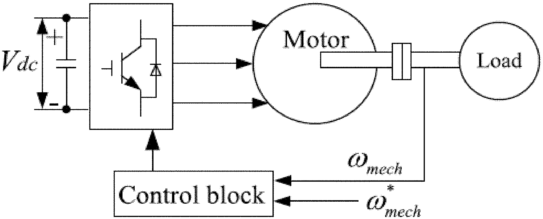
[0017] FIG. 1 shows a simple schematic of three-phase induction motor drive, in which a dc voltage source is on the left and the control block plays the role of regulating the motor speed through a voltage source pulse width modulation (PWM) converter;
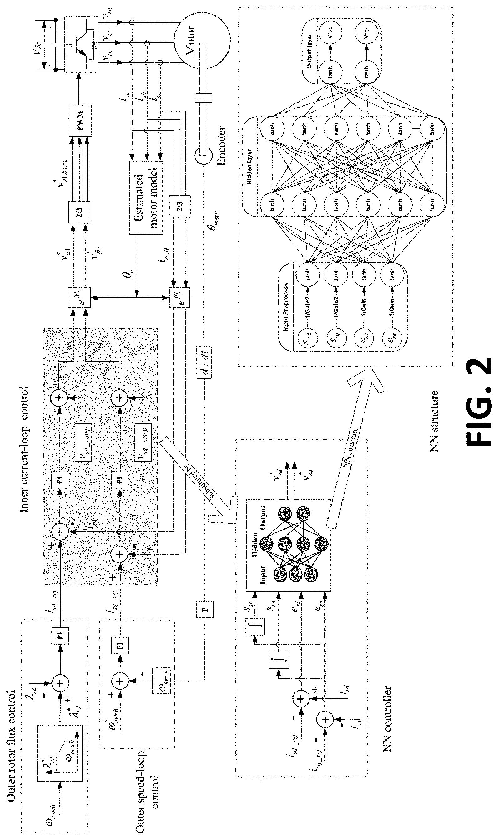
[0018] FIG. 2 shows a proposed NN vector control architecture for an induction motor;
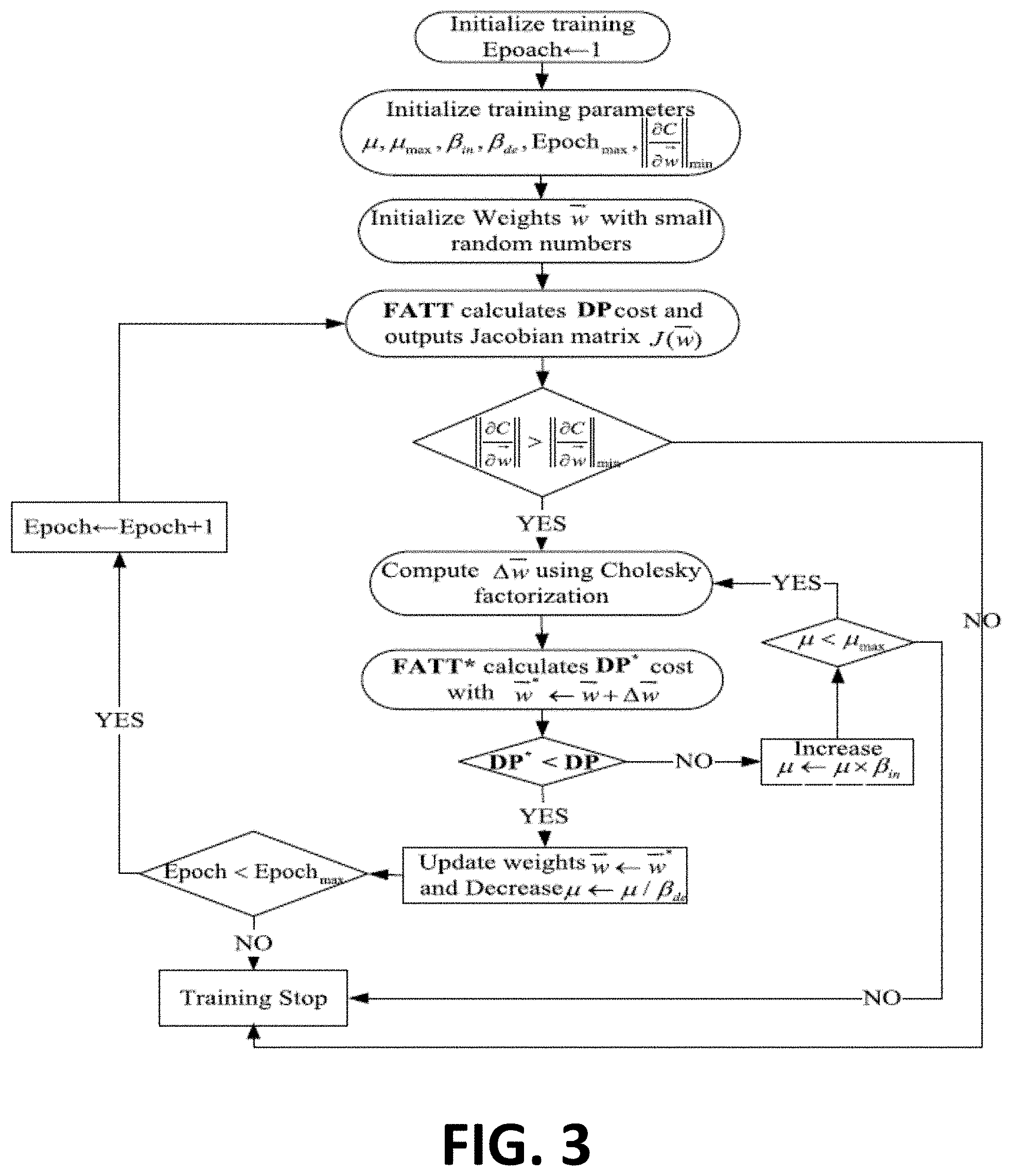
[0019] FIG. 3 is a flowchart that presents the process of LM algorithm for training an NN controller and also demonstrates how to adjust .mu. dynamically to ensure that the training follows the decreasing direction of the DP cost function;
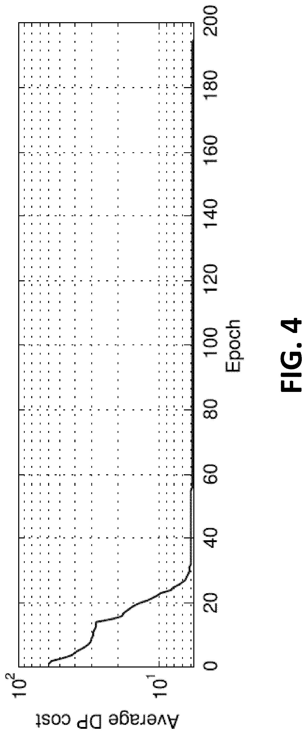
[0020] FIG. 4 shows a learning curve for a successful training of a NN controller;
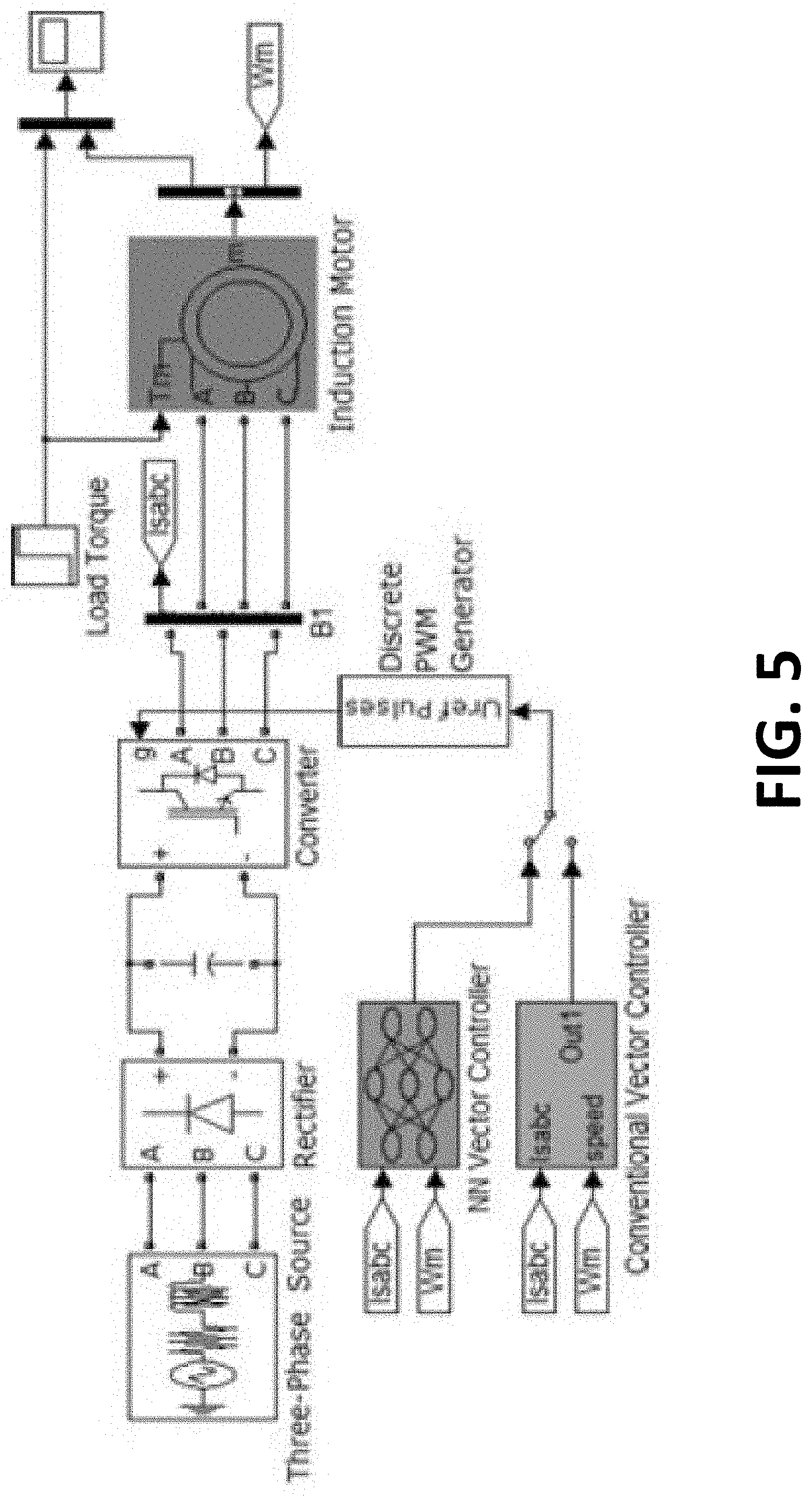
[0021] FIG. 5 illustrates a Simulink model of a three-phase induction motor drive system;
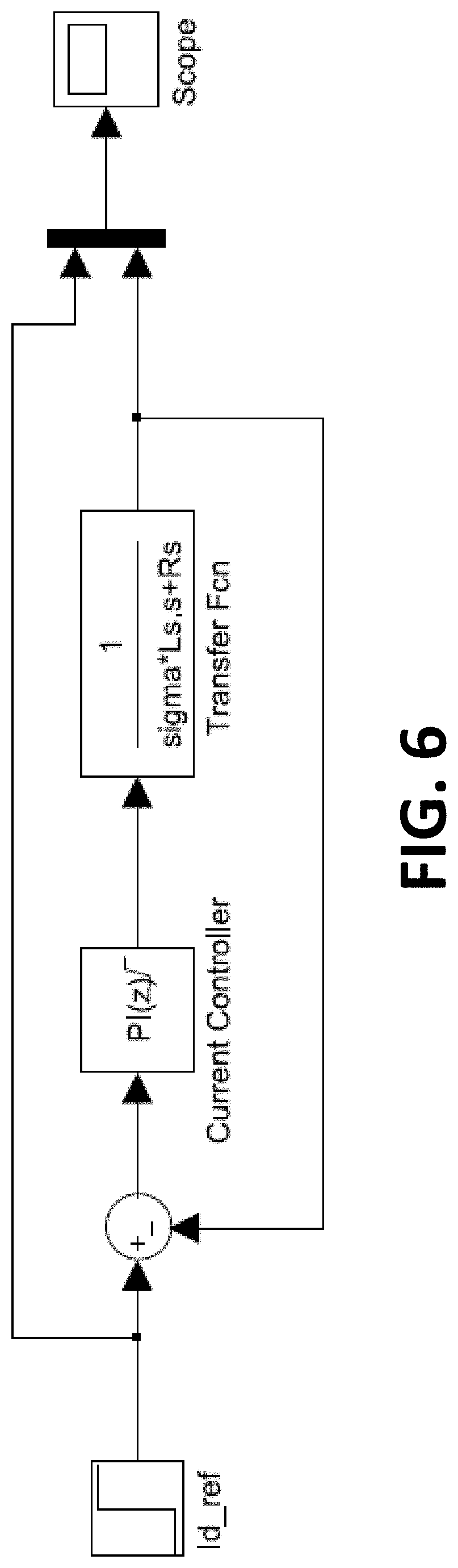
[0022] FIG. 6 illustrates a block diagram for tuning a current-loop PI controller;
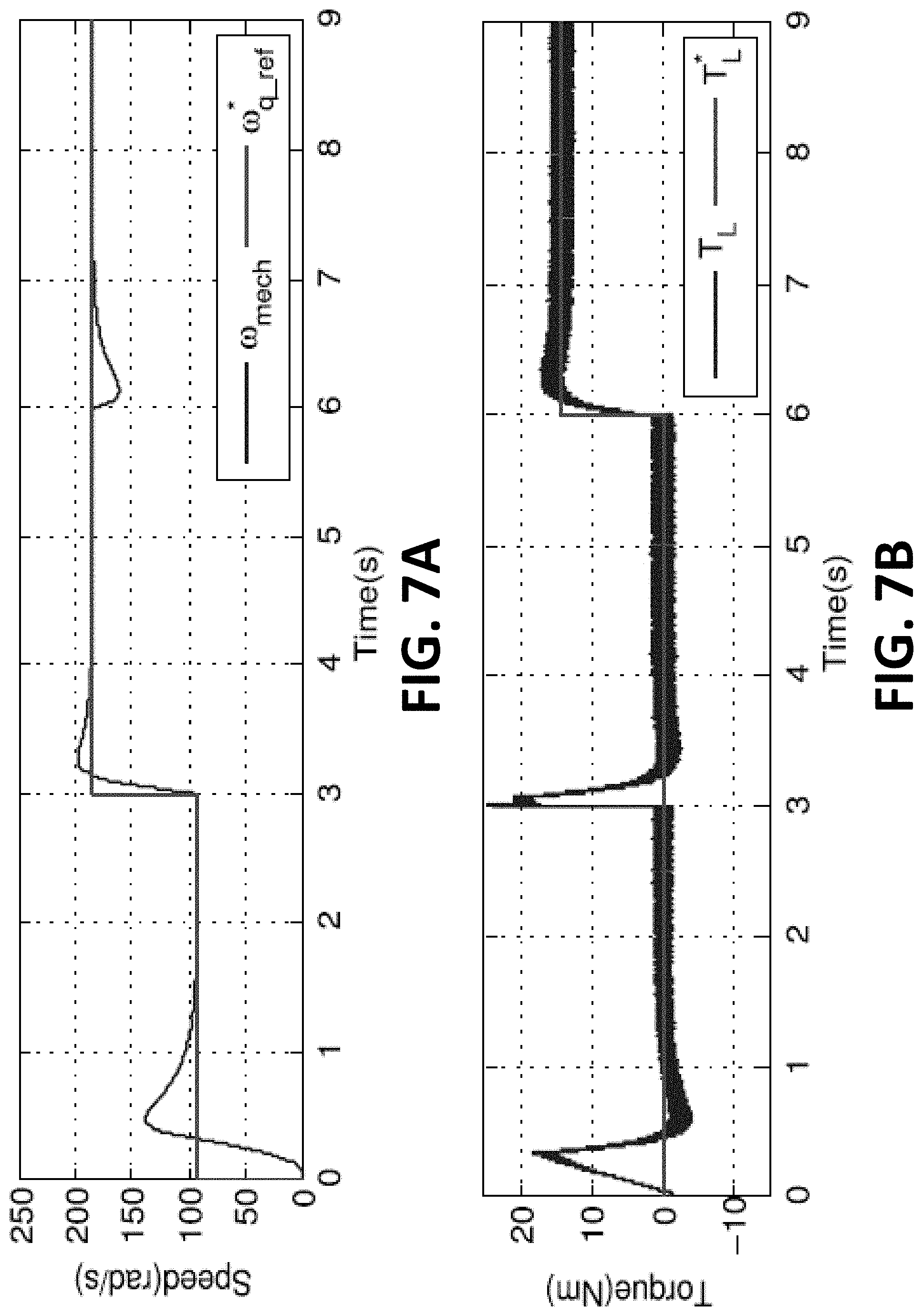
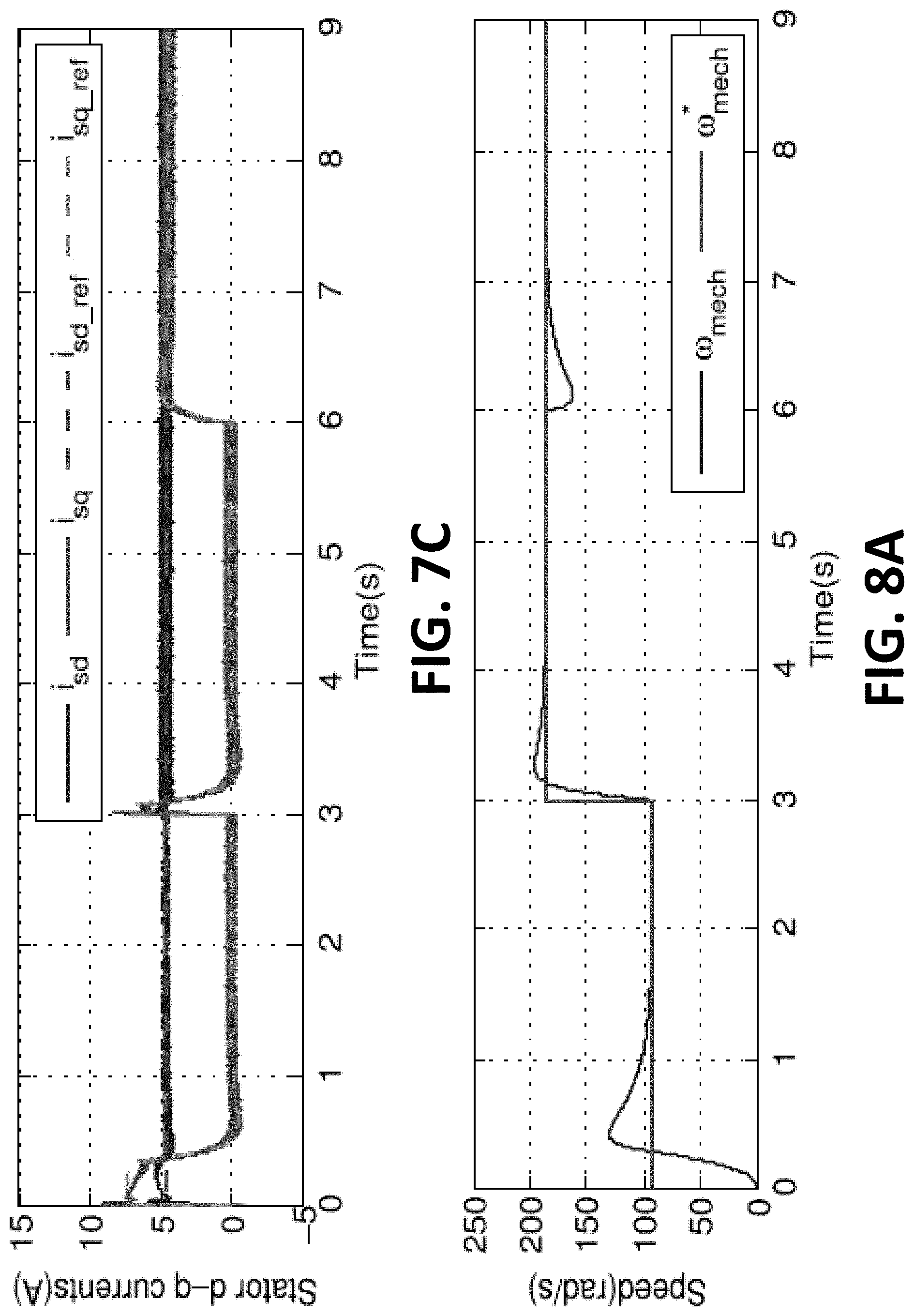
[0023] FIGS. 7A-7C illustrate conventional vector control in an induction motor where 7A shows speed, 7B shows torque and 7C shows stator dq currents;
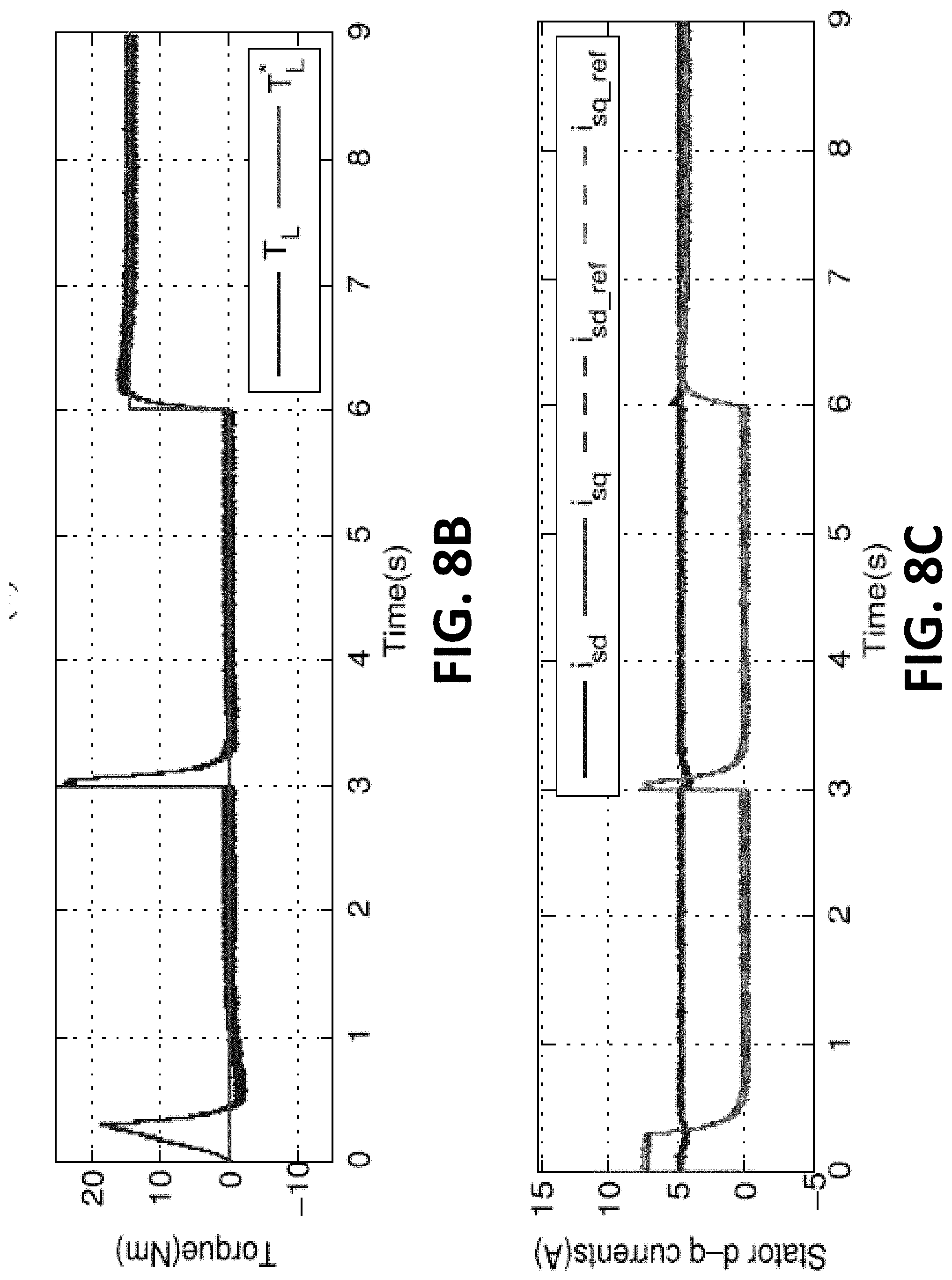
[0024] FIGS. 8A-8C illustrate neural network vector control in an induction motor where 8A shows speed, 8B shows torque and 8C shows stator dq currents;
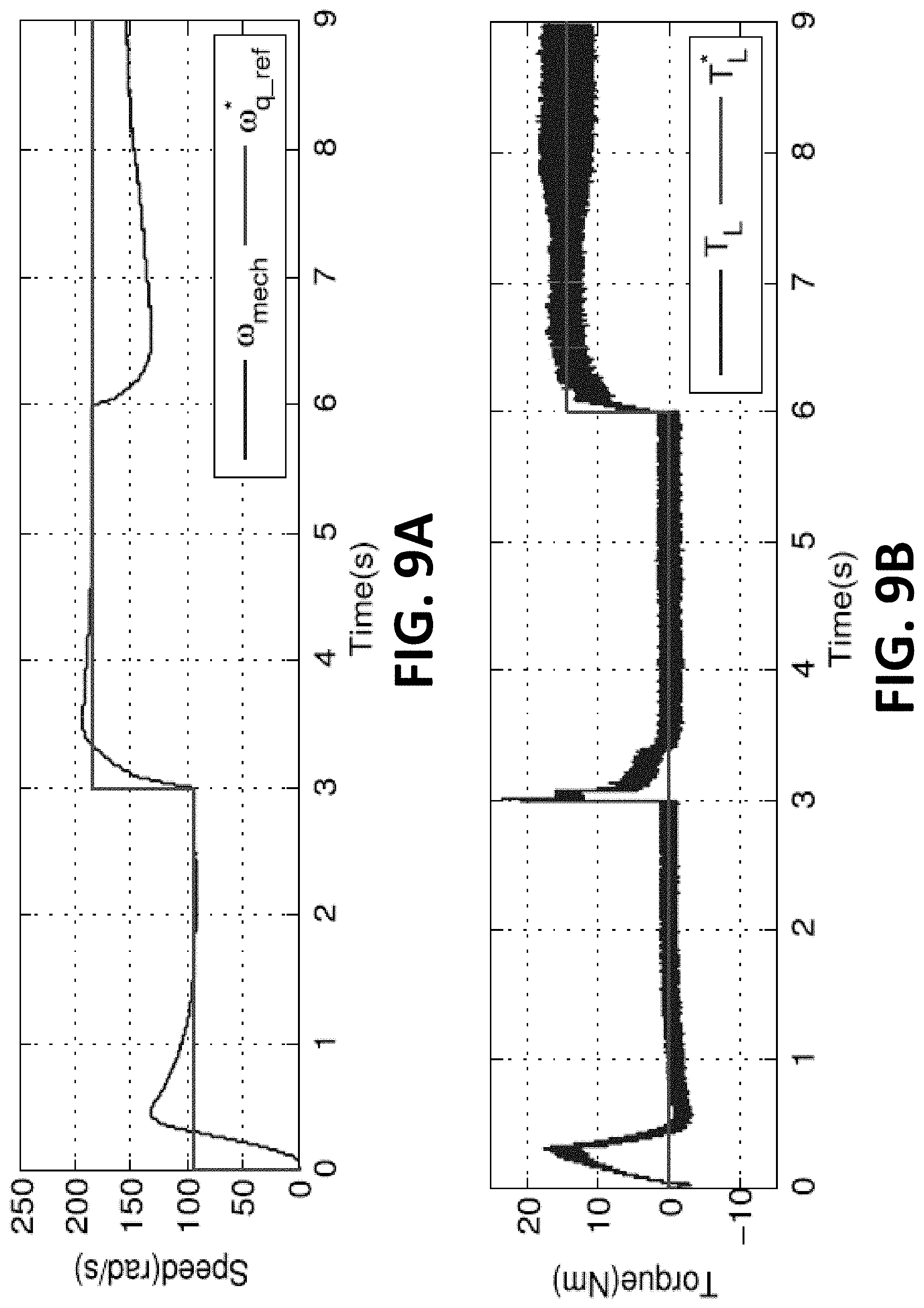
[0025] FIGS. 9A-9C illustrate conventional vector control with new settings R*.sub.r=3R.sub.r in an induction motor where 9A shows speed, 9B shows torque and 9C shows stator dq currents;
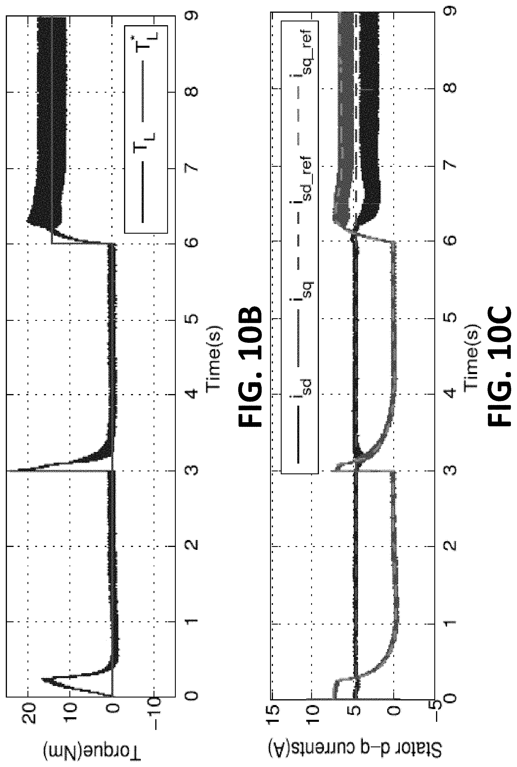
[0026] FIGS. 10A-10C illustrate neural network vector control with new settings R*.sub.r=3R.sub.r in an induction motor where 10A shows speed, 10B shows torque and 10C shows stator dq currents;
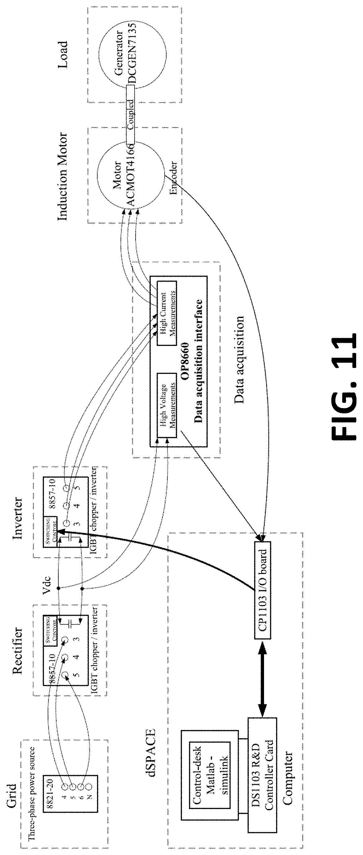
[0027] FIG. 11 illustrates a schematic of an induction motor drive experiment;
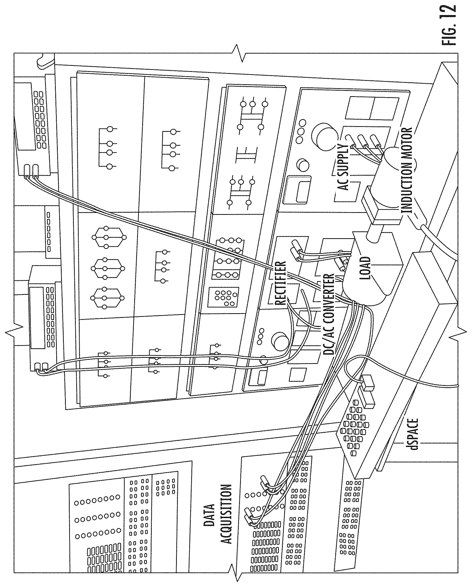
[0028] FIG. 12 is a photograph that shows the hardware testing and control systems during an experiment of aspects of the present invention;
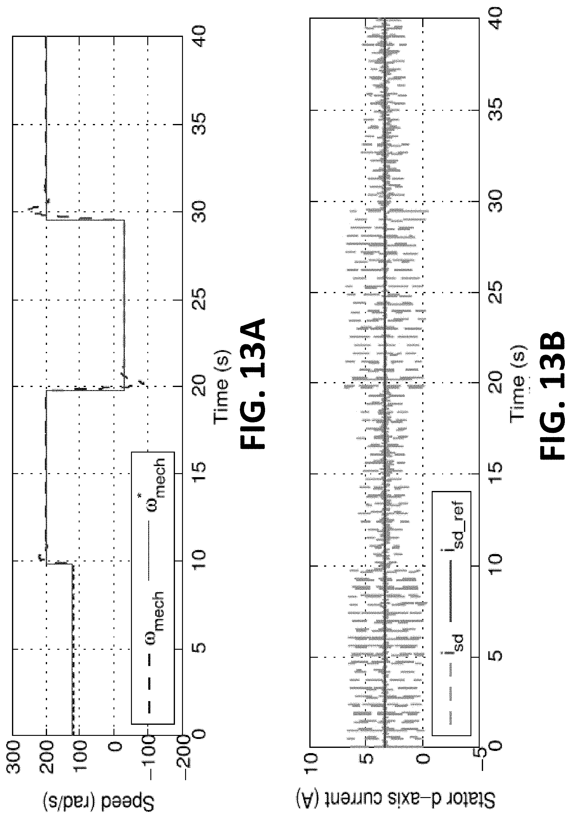
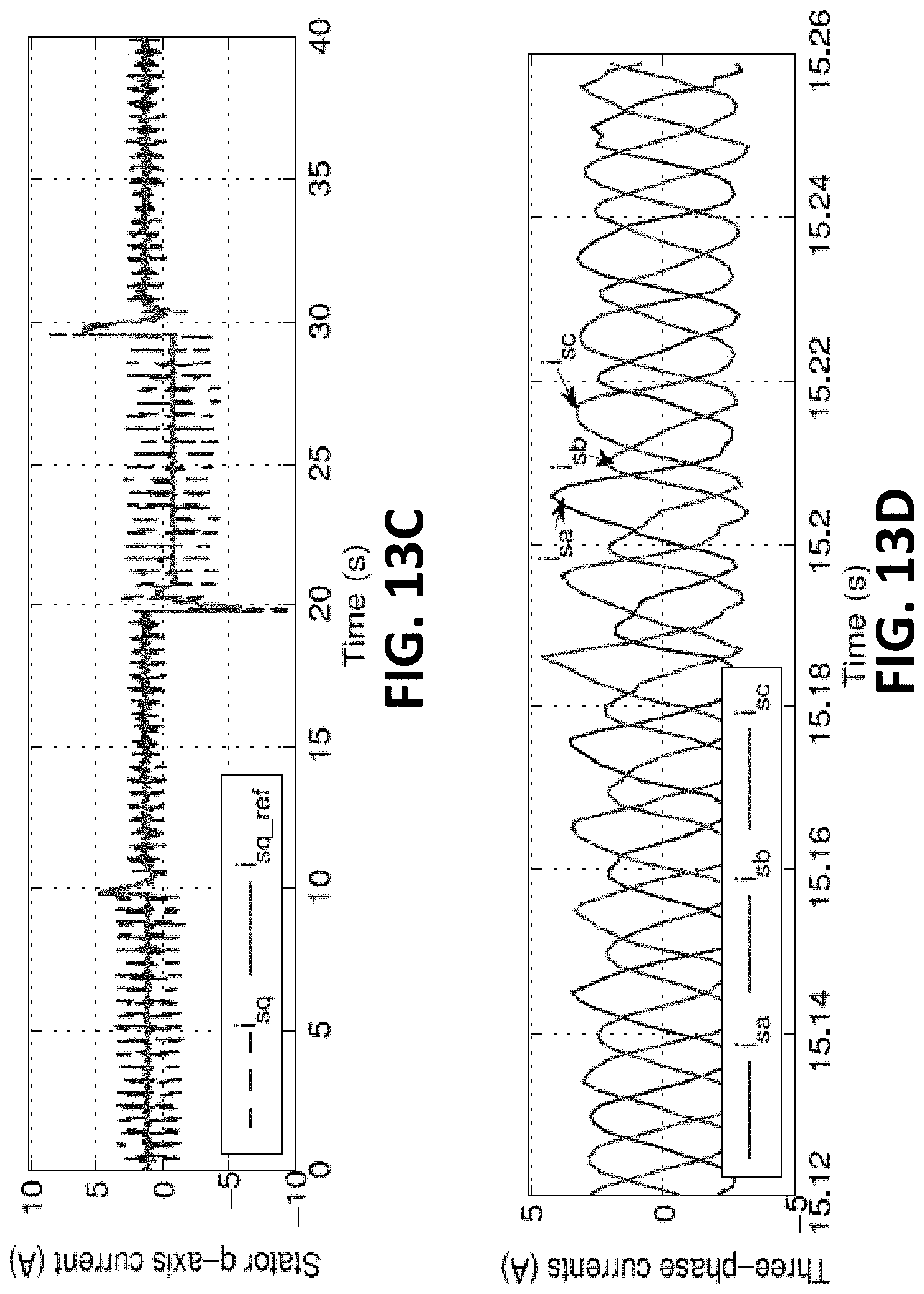
[0029] FIGS. 13A-13D illustrate conventional vector control of an induction motor during an induction motor drive experiment with T.sub.s=0.5 ms and f.sub.s=6 kHz where 13A shows speed, 13B shows stator d-axis current, 13C shows stator q-axis currents and 13D shows three-phase currents;
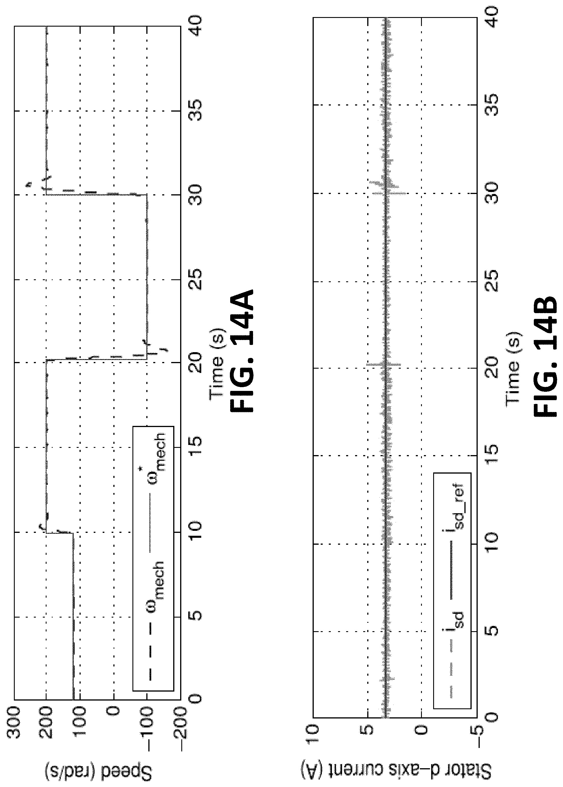
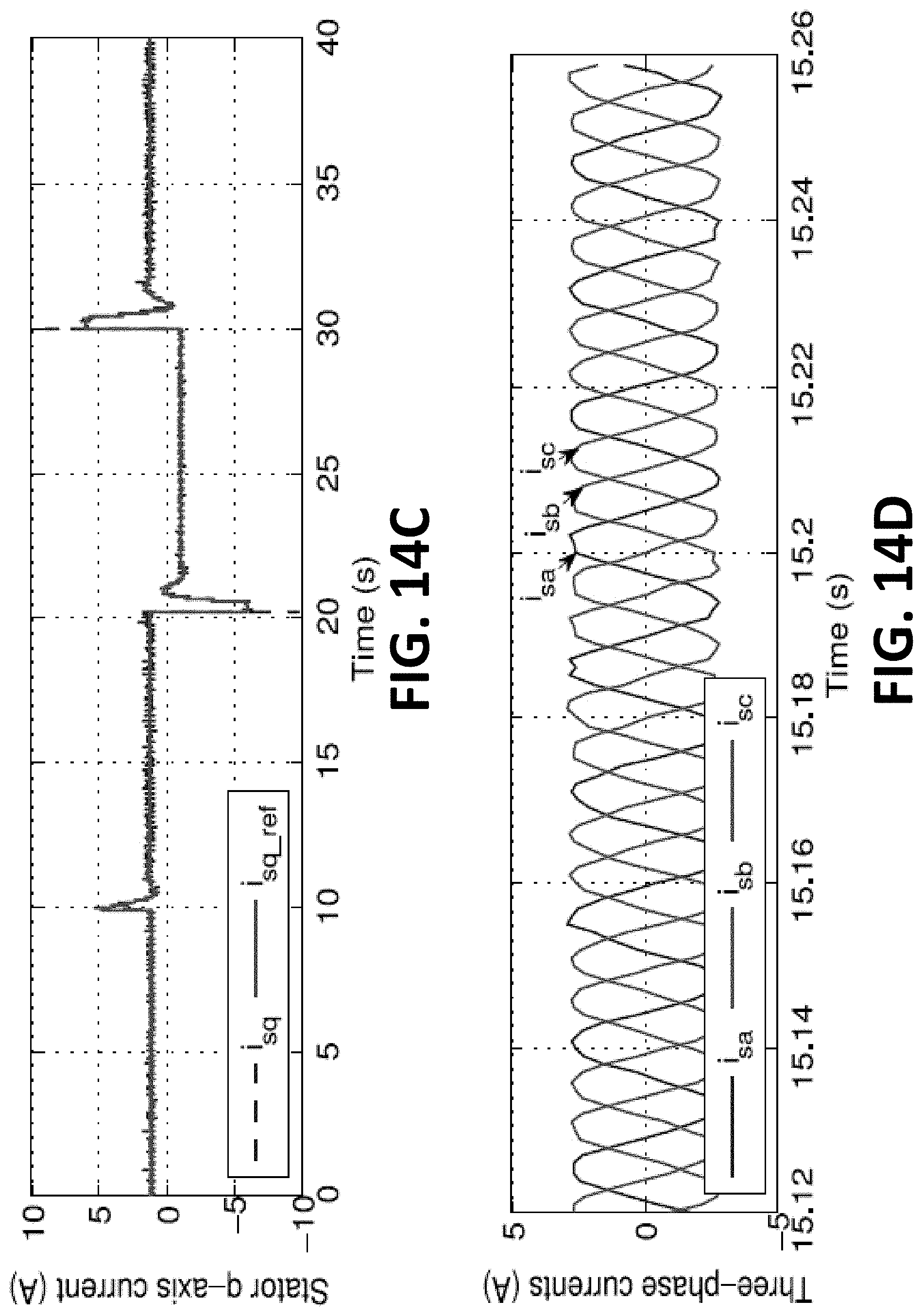
[0030] FIGS. 14A-14D illustrate NN vector control of an induction motor during an induction motor drive experiment with TS=0.5 ms and f, =6 kHz where 14A shows speed, 14B shows stator d-axis current, 14C shows stator q-axis currents and 14D shows three-phase currents;
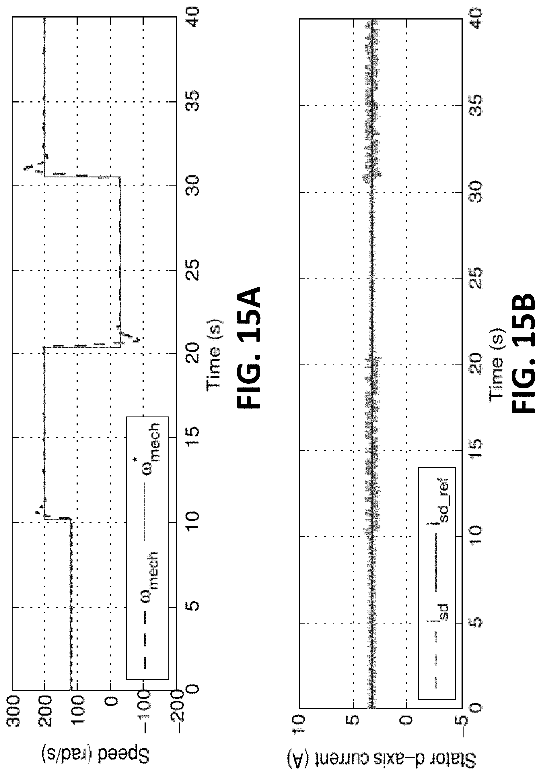
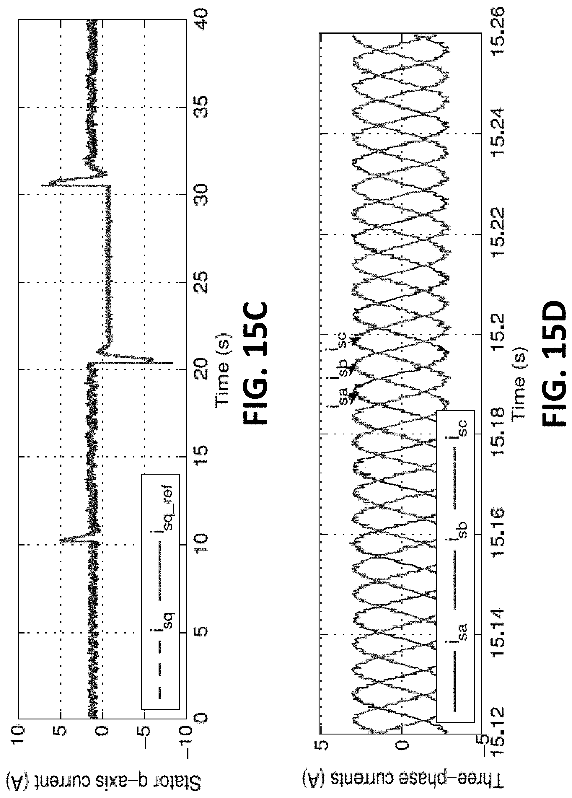
[0031] FIGS. 15A-15D illustrate conventional vector control of an induction motor during an induction motor drive experiment with Ts=0.1 ms and f, =6 kHz where 15A shows speed, 15B shows stator d-axis current, 15C shows stator q-axis currents and 15D shows three-phase currents; and
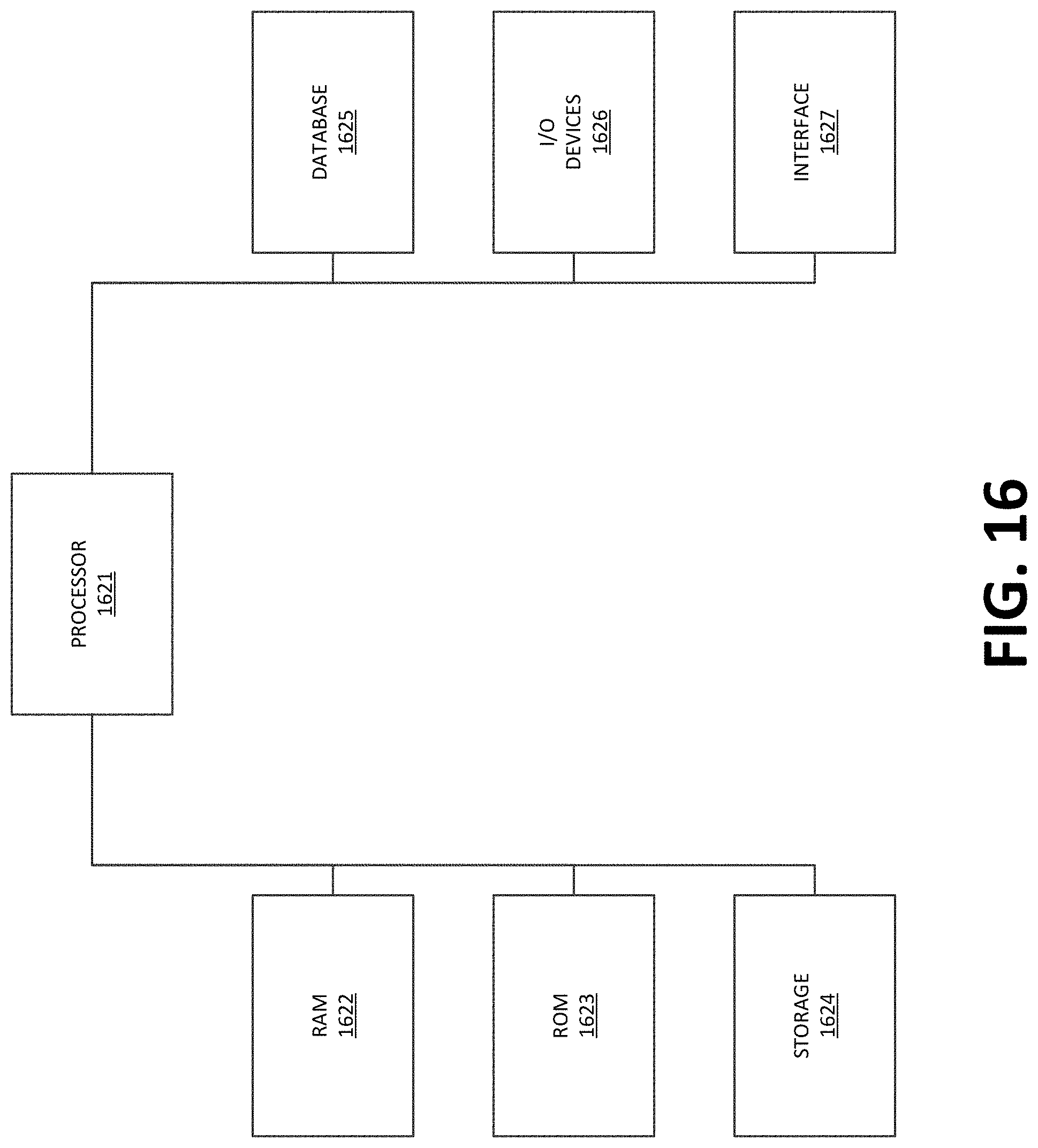
[0032] FIG. 16 illustrates an exemplary computer that can be used for controlling an induction motor.
DETAILED DESCRIPTION
[0033] Unless defined otherwise, all technical and scientific terms used herein have the same meaning as commonly understood by one of ordinary skill in the art. Methods and materials similar or equivalent to those described herein can be used in the practice or testing of the present disclosure. As used in the specification, and in the appended claims, the singular forms "a," "an," "the" include plural referents unless the context clearly dictates otherwise. The term "comprising" and variations thereof as used herein is used synonymously with the term "including" and variations thereof and are open, non-limiting terms. The terms "optional" or "optionally" used herein mean that the subsequently described feature, event or circumstance may or may not occur, and that the description includes instances where said feature, event or circumstance occurs and instances where it does not.
[0034] Before the present methods and systems are disclosed and described, it is to be understood that the methods and systems are not limited to specific synthetic methods, specific components, or to particular compositions. It is also to be understood that the terminology used herein is for the purpose of describing particular embodiments only and is not intended to be limiting.
[0035] As used in the specification and the appended claims, the singular forms "a," "an" and "the" include plural referents unless the context clearly dictates otherwise. Ranges may be expressed herein as from "about" one particular value, and/or to "about" another particular value. When such a range is expressed, another embodiment includes from the one particular value and/or to the other particular value. Similarly, when values are expressed as approximations, by use of the antecedent "about," it will be understood that the particular value forms another embodiment. It will be further understood that the endpoints of each of the ranges are significant both in relation to the other endpoint, and independently of the other endpoint.
[0036] "Optional" or "optionally" means that the subsequently described event or circumstance may or may not occur, and that the description includes instances where said event or circumstance occurs and instances where it does not.
[0037] Throughout the description and claims of this specification, the word "comprise" and variations of the word, such as "comprising" and "comprises," means "including but not limited to," and is not intended to exclude, for example, other additives, components, integers or steps. "Exemplary" means "an example of" and is not intended to convey an indication of a preferred or ideal embodiment. "Such as" is not used in a restrictive sense, but for explanatory purposes.
[0038] Disclosed are components that can be used to perform the disclosed methods and systems. These and other components are disclosed herein, and it is understood that when combinations, subsets, interactions, groups, etc. of these components are disclosed that while specific reference of each various individual and collective combinations and permutation of these may not be explicitly disclosed, each is specifically contemplated and described herein, for all methods and systems. This applies to all aspects of this application including, but not limited to, steps in disclosed methods. Thus, if there are a variety of additional steps that can be performed it is understood that each of these additional steps can be performed with any specific embodiment or combination of embodiments of the disclosed methods.
[0039] As will be appreciated by one skilled in the art, the methods and systems may take the form of an entirely hardware embodiment, an entirely software embodiment, or an embodiment combining software and hardware aspects. Furthermore, the methods and systems may take the form of a computer program product on a computer-readable storage medium having computer-readable program instructions (e.g., computer software) embodied in the storage medium. More particularly, the present methods and systems may take the form of web-implemented computer software. Any suitable computer-readable storage medium may be utilized including hard disks, CD-ROMs, optical storage devices, or magnetic storage devices.
[0040] Embodiments of the methods and systems are described below with reference to block diagrams and flowchart illustrations of methods, systems, apparatuses and computer program products. It will be understood that each block of the block diagrams and flowchart illustrations, and combinations of blocks in the block diagrams and flowchart illustrations, respectively, can be implemented by computer program instructions. These computer program instructions may be loaded onto a general purpose computer, special purpose computer, or other programmable data processing apparatus to produce a machine, such that the instructions which execute on the computer or other programmable data processing apparatus create a means for implementing the functions specified in the flowchart block or blocks.
[0041] These computer program instructions may also be stored in a computer-readable memory that can direct a computer or other programmable data processing apparatus to function in a particular manner, such that the instructions stored in the computer-readable memory produce an article of manufacture including computer-readable instructions for implementing the function specified in the flowchart block or blocks. The computer program instructions may also be loaded onto a computer or other programmable data processing apparatus to cause a series of operational steps to be performed on the computer or other programmable apparatus to produce a computer-implemented process such that the instructions that execute on the computer or other programmable apparatus provide steps for implementing the functions specified in the flowchart block or blocks.
[0042] Accordingly, blocks of the block diagrams and flowchart illustrations support combinations of means for performing the specified functions, combinations of steps for performing the specified functions and program instruction means for performing the specified functions. It will also be understood that each block of the block diagrams and flowchart illustrations, and combinations of blocks in the block diagrams and flowchart illustrations, can be implemented by special purpose hardware-based computer systems that perform the specified functions or steps, or combinations of special purpose hardware and computer instructions.
[0043] The present methods and systems may be understood more readily by reference to the following detailed description of preferred embodiments and the Examples included therein and to the Figures and their previous and following description.
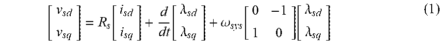
[0044] FIG. 1 shows a simple schematic of three-phase induction motor drive, in which a dc voltage source is on the left and the control block plays the role of regulating the motor speed through a voltage source pulse width modulation (PWM) converter. In the dq domain, the stator voltage equations is written as:
[ v sd v sq ] = R s [ i sd i sq ] + d dt [ .lamda. sd .lamda. sq ] + .omega. sys [ 0 - 1 1 0 ] [ .lamda. sd .lamda. sq ] ( 1 ) ##EQU00001##
where R.sub.s is the per phase resistance of the stator winding, .omega..sub.sys is the synchronous speed of the induction motor, and v.sub.sd, v.sub.sq, i.sub.sd, i.sub.sq, .lamda..sub.sd, and .lamda..sub.sq are the d and q components of stator d-axis voltage, stator q-axis voltage, stator d-axis current, stator q-axis current, stator d-axis flux, and stator q-axis flux, respectively.
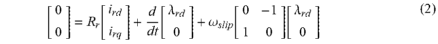
[0045] Using the rotor flux-oriented frame, that is rotor q-axis flux .lamda..sub.rq=0, the rotor voltage equation is shown by:
[ 0 0 ] = R r [ i rd i rq ] + d dt [ .lamda. rd 0 ] + .omega. slip [ 0 - 1 1 0 ] [ .lamda. rd 0 ] ( 2 ) ##EQU00002##
where R.sub.r, .omega..sub.slip, i.sub.rd, i.sub.rq, .lamda..sub.rd, and .lamda..sub.rq stand for per-phase rotor resistance, rotor slip speed, rotor d-axis current, rotor q-axis current, rotor d-axis flux, and rotor q-axis flux, respectively. Especially, the rotor slip speed .omega..sub.Slip equals the difference between the synchronous speed .omega..sub.sys and rotor speed .omega..sub.m, e.g., .omega..sub.slip=.omega..sub.sys-.omega..sub.m.
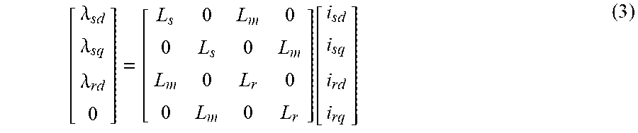
[0046] The flux linkage equation can be expressed as:
[ .lamda. sd .lamda. sq .lamda. rd 0 ] = [ L s 0 L m 0 0 L s 0 L m L m 0 L r 0 0 L m 0 L r ] [ i sd i sq i rd i rq ] ( 3 ) ##EQU00003##
where L.sub.s, L.sub.r, and L.sub.m represent per-phase stator inductance, per-phase rotor inductance, and per-phase stator magnetizing inductance. Especially, L.sub.s=L_.sub.s+L.sub.m and L.sub.r=L_.sub.r+L.sub.m. L and L_.sub.r refer to per-phase stator leakage inductance and per-phase rotor leakage inductance, respectively.
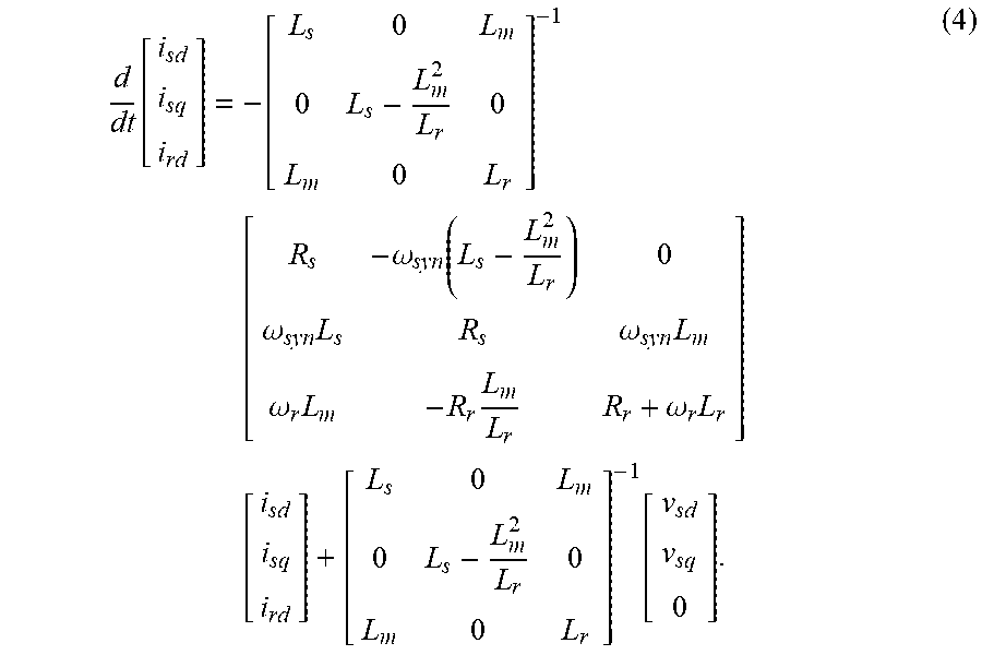
[0047] The induction motor model (1)-(3) can be rearranged into the standard state-space representation shown by:
d dt [ i sd i sq i rd ] = - [ L s 0 L m 0 L s - L m 2 L r 0 L m 0 L r ] - 1 [ R s - .omega. syn ( L s - L m 2 L r ) 0 .omega. syn L s R s .omega. syn L m .omega. r L m - R r L m L r R r + .omega. r L r ] [ i sd i sq i rd ] + [ L s 0 L m 0 L s - L m 2 L r 0 L m 0 L r ] - 1 [ v sd v sq 0 ] . ( 4 ) ##EQU00004##
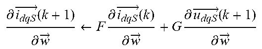
[0048] Define {right arrow over (i.sub.dqS)}=[i.sub.sd i.sub.sq i.sub.rd]' and {right arrow over (u.sub.dqS)}=[v.sub.sd v.sub.sq 0]'. To implement recurrent neural network (RNN)-based digital controller, the continuous state-space model (4) needs to be transferred into the equivalent discrete model (5) through either a zero-order or first-order hold discrete equivalent mechanism:
{right arrow over (i.sub.dqS)}(k+1)=F{right arrow over (i.sub.dqS)}(k)+G{right arrow over (u.sub.dqS)}(k) (5)
where k is an integer time step, F is the system matrix, and G is the matrix associated with the control voltage. Note that {right arrow over (i.sub.sdq)}=[i.sub.sd i.sub.sq]' are the state variables that needs to be controlled and are the control actions.
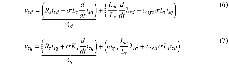
[0049] The standard vector controller has a nested-loop structure comprised of a faster inner current loop and a slower outer speed and rotor flux loop. A fast inner current loop is important to ensure high-quality ac drive of an induction motor. The outer speed and rotor flux loop generates d- and q-axis current references to the inner current-loop controller, while the inner current-loop controller implements the final control function by applying a voltage signal to the PWM inverter. The conventional control strategy of the current loop is developed by rewriting Equations (1)-(3) as:
v sd = ( R s i sd + .sigma. L s d dt i sd ) v sd ' + ( L m L r d dt .lamda. rd - .omega. sys .sigma. L s i sq ) ( 6 ) v sq = ( R s i sq + .sigma. K s d dt i sq ) v sq ' + ( .omega. sys L m L r .lamda. rd + .omega. sys .sigma. L s i sd ) ( 7 ) ##EQU00005##
where a is the leakage factor of the induction machine and defined as .sigma.=1 (L.sub.m).sup.2/L.sub.sL.sub.r. Those items denoted as v'.sub.sd and v'.sub.sq are treated as the state equations between the input voltages and output currents for the d- and q-axis current loops and the other terms are regarded as compensation items. Therefore, the corresponding transfer function 1/(R.sub.S+sqL.sub.S) is used to design the current-loop controller.
[0050] The design of speed loop is based on the following equations:
d dt .omega. mech = T em - T L J eq , T em = p 2 L m 2 L r i sd * K T i sq ( 8 ) ##EQU00006##
where p means pole numbers of the motor, i*.sub.sd is the reference value of i.sub.sd, and K.sub.T is constant.
[0051] A proposed NN vector control architecture for an induction motor is shown in FIG. 2. The NN implements the fast inner current-loop control function. Due to the universal function approximation property, NN vector control, unlike conventional vector control, has the ability to achieve true decoupled torque and flux control. The outer control loops still utilize PI controllers and q-axis loop is used for speed control as shown in FIG. 2.
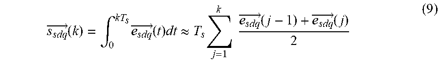
[0052] The proposed current-loop NN controller as shown in FIG. 2 is comprised of two parts: input preprocessing block and a four-layer feed-forward network. To avoid input saturation, the inputs are regulated to the range [-1, 1] through a preprocessing procedure. The inputs to the feed-forward network are tanh({right arrow over (e.sub.sdq)}/Gain) and tanh({right arrow over (s.sub.sdq)}/Gain2) where {right arrow over (e.sub.sdq)} and {right arrow over (s.sub.sdq)} are error terms and integrals of the error terms. {right arrow over (e.sub.sdq)} is defined as {right arrow over (e.sub.sdq)}(k)={right arrow over (sdq)}(k)-{right arrow over (.sub.sdq_ref)}(k) and {right arrow over (s.sub.sdq)}(k) is calculated by:
s sdq .fwdarw. ( k ) = .intg. 0 kT s e sdq .fwdarw. ( t ) dt .apprxeq. T s j = 1 k e sdq .fwdarw. ( j - 1 ) + e sdq .fwdarw. ( j ) 2 ( 9 ) ##EQU00007##
in which the trapezoid formula was used to compute the integral term {right arrow over (s.sub.sdq)} (k) and {right arrow over (e.sub.sdq)} (0).ident.0.
[0053] The feed-forward network contains two hidden layers of six nodes each, and two output nodes, with hyperbolic tangent functions at all nodes. Two hidden layers were chosen to yield a stronger approximation ability. The selection of the number of neurons in each hidden layer was done through trial and error tests. Basically, six nodes in each hidden layer can give good enough results. Even though the feed-forward network in FIG. 2 does not have a feedback connection, the proposed NN current controller shown in FIG. 2 actually is a RNN because the current feedback signal generated by the system (4) acts as a recurrent network connection from the output of NN back to the input. A recurrent network is potentially more powerful than a feedforward network and can exhibit temporal behavior, which may be particularly important for feedback control applications.
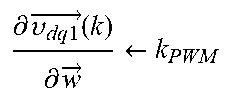
[0054] According to FIG. 2, the NN current-loop controller can be denoted as R({right arrow over (e.sub.sdq)}, {right arrow over (s.sub.sdq)},.omega.)), which is a function of {right arrow over (e.sub.sdq)}, {right arrow over (s.sub.sdq)}, and network weights {right arrow over (.omega.)}. As the ratio of the converter output voltage {right arrow over (v.sub.sdq)} to the outputs of the current loop controller {right arrow over (v*.sub.sdq)} is the gain of the PWM, which is denoted as k.sub.PWM, the control action {right arrow over (v.sub.sdq)} is then expressed by:
{right arrow over (v.sub.sdq)}=k.sub.PWM{right arrow over (v*.sub.sdq)}=k.sub.PWMR({right arrow over (e.sub.sdq)},{right arrow over (s.sub.sdq)},.omega.) (10)
[0055] Training the Neural Network Controller
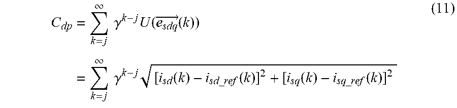
[0056] DP employs the principle of Bellman's optimality (see, R. E. Bellman, Dynamic Programming. Princeton, N.J., USA: Princeton Univ. Press, 1957, which is incorporated by reference) and is a very useful tool for solving optimization and optimal control problems. The DP cost function associated with the induction motor system is defined as:
C dp = k = j .infin. .gamma. k - j U ( e sdq .fwdarw. ( k ) ) = k = j .infin. .gamma. k - j [ i sd ( k ) - i sd _ ref ( k ) ] 2 + [ i sq ( k ) - i sq _ ref ( k ) ] 2 ( 11 ) ##EQU00008##
where .gamma. is a discount factor with 0<.gamma..ltoreq.1 and j>0. U is called local cost or utility function. The function C.sub.dp, depending on the initial time j>0 and the initial state {right arrow over (.sub.sdq)}(j), is referred to as the cost-to-go of state {right arrow over (.sub.sdq)} (j) of the DP problem.
[0057] The objective of the training is to find an optimal trajectory of control action v.sub.dql that minimizes the DP cost C.sub.dp in (11).
[0058] One method of training the NN s by use of a Levenberg-Marquardt (LM) algorithm. An advantage of the LM algorithm is that is that it appears to be the fastest NN training algorithm, for a moderate number of network parameters. Also, LM usually can achieve better convergency performance than BPTT in training the RNN.
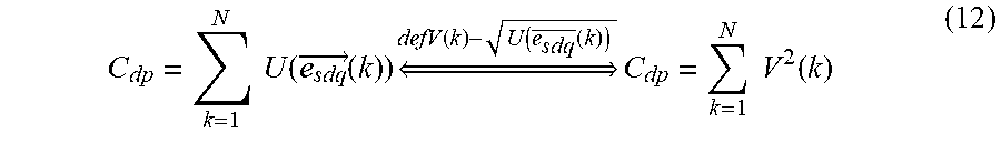
[0059] To implement LM training, the cost function defined in (11) needs to be rewritten in a sum-of-squares form. Consider the cost function C.sub.dp with .gamma.=1, j=1 and k=1, . . . , N; then, it can be written in the form:
C dp = k = 1 N U ( e sdq .fwdarw. ( k ) ) defV ( k ) - U ( e sdq .fwdarw. ( k ) ) C dp = k = 1 N V 2 ( k ) ( 12 ) ##EQU00009##
and the gradient
.differential. C dp .differential. w ##EQU00010##
can be written in a matrix product form:
.differential. C dp .differential. w .fwdarw. = k = 1 N V ( k ) .differential. V ( k ) .differential. w = 2 J v ( w .fwdarw. ) T V ( 13 ) ##EQU00011##
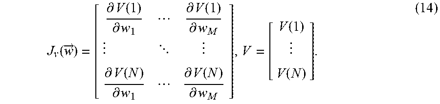
In which, the Jacobian matrix J.sub.v({right arrow over (w)}) is:
J v ( w .fwdarw. ) = [ .differential. V ( 1 ) .differential. w 1 .differential. V ( 1 ) .differential. w M .differential. V ( N ) .differential. w 1 .differential. V ( N ) .differential. w M ] , V = [ V ( 1 ) V ( N ) ] . ( 14 ) ##EQU00012##
Therefore, the weights update by using LM for an NN controller can be expressed as:
.DELTA.{right arrow over (.omega.)}=[J.sub.v({right arrow over (.omega.)}).sup.TJ.sub.v({right arrow over (.omega.)})+.mu.I].sup.-1J.sub.v({right arrow over (.omega.)}).sup.TV. (15)
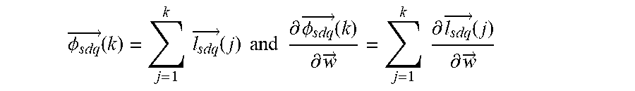
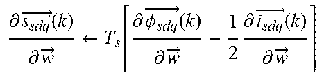
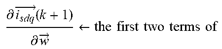
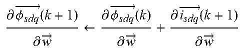
[0060] Forward Accumulation Through Time (FATT) Algorithm: The calculation of Jacobian matrix J.sub.v(w) needs to pass through the system equations (5). In order to find Jacobian matrix J.sub.v({right arrow over (w)}) efficiently, FATT is used for the induction motor, which incorporates the procedures of unrolling the system, calculating the derivatives of the Jacobian matrix, and calculating the DP cost into one single process for each training epoch. Algorithm 1, below, describes the whole algorithm. Denote
.phi. sdq .fwdarw. ( k ) = j = 1 k l sdq .fwdarw. ( j ) and .differential. .phi. sdq .fwdarw. ( k ) .differential. w .fwdarw. = j = 1 k .differential. l sdq .fwdarw. ( j ) .differential. w .fwdarw. ##EQU00013##
in the algorithm.
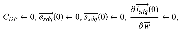
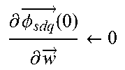
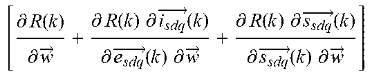
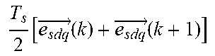
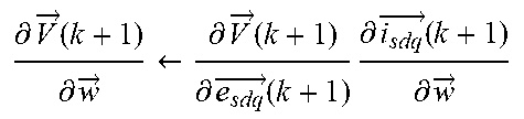
TABLE-US-00001 Algorithm 1 FATT algorithm to calculate the Jacobian matrix and to accumulate DP cost. 1: C DP .rarw. 0 , e sdq .fwdarw. ( 0 ) .rarw. 0 , s sdq .fwdarw. ( 0 ) .rarw. 0 , .differential. i sdq .fwdarw. ( 0 ) .differential. w .fwdarw. .rarw. 0 , ##EQU00014## .differential. .phi. sdq .fwdarw. ( 0 ) .differential. w .fwdarw. .rarw. 0 ##EQU00015## 2: {Calculate the Jacobian matrix J.sub..upsilon.({right arrow over (w)})} 3: for k = 0 to N - 1 do 4: {right arrow over (.upsilon..sub.dq1)}(k) .rarw. k.sub.PWM R({right arrow over (e.sub.sdq)}(k), {right arrow over (s.sub.sdq)}(k), {right arrow over (w)}) 5: .differential. s sdq .fwdarw. ( k ) .differential. w .fwdarw. .rarw. T s [ .differential. .phi. sdq .fwdarw. ( k ) .differential. w .fwdarw. - 1 2 .differential. i sdq .fwdarw. ( k ) .differential. w .fwdarw. ] ##EQU00016## 6: .differential. .upsilon. dq 1 .fwdarw. ( k ) .differential. w .fwdarw. .rarw. k PWM ##EQU00017## [ .differential. R ( k ) .differential. w .fwdarw. + .differential. R ( k ) .differential. i sdq .fwdarw. ( k ) .differential. e sdq .fwdarw. ( k ) .differential. w .fwdarw. + .differential. R ( k ) .differential. s sdq .fwdarw. ( k ) .differential. s sdq .fwdarw. ( k ) .differential. w .fwdarw. ] ##EQU00018## 7: .differential. i dqS .fwdarw. ( k + 1 ) .differential. w .fwdarw. .rarw. F .differential. i dqS .fwdarw. ( k ) .differential. w .fwdarw. + G .differential. u dqS .fwdarw. ( k + 1 ) .differential. w .fwdarw. ##EQU00019## 8: .differential. i sdq .fwdarw. ( k + 1 ) .differential. w .fwdarw. .rarw. the first two terms of ##EQU00020## .differential. i dqS .fwdarw. ( k + 1 ) .differential. w .fwdarw. ##EQU00021## 9: .differential. .phi. sdq .fwdarw. ( k + 1 ) .differential. w .fwdarw. .rarw. .differential. .phi. sdq .fwdarw. ( k ) .differential. w .fwdarw. + .differential. i sdq .fwdarw. ( k + 1 ) .differential. w .fwdarw. ##EQU00022## 10: {right arrow over (i.sub.dqS)}(k + 1) .rarw. F{right arrow over (i.sub.dqS)}(k) + G{right arrow over (u.sub.dqS)}(k) 11: {right arrow over (e.sub.sdq)}(k + 1) .rarw. {right arrow over (i.sub.sdq)}(k + 1) - {right arrow over (i.sub.sdq_ref)}(k + 1) 12: {right arrow over (s.sub.sdq)}(k + 1) .rarw. {right arrow over (s.sub.sdq)}(k) + T s 2 [ e sdq .fwdarw. ( k ) + e sdq .fwdarw. ( k + 1 ) ] ##EQU00023## 13: C.sub.DP .rarw. C.sub.DP + U({right arrow over (e.sub.sdq)}(k + 1)) {accumulate DP cost} 14: .differential. V .fwdarw. ( k + 1 ) .differential. w .fwdarw. .rarw. .differential. V .fwdarw. ( k + 1 ) .differential. e sdq .fwdarw. ( k + 1 ) .differential. i sdq .fwdarw. ( k + 1 ) .differential. w .fwdarw. ##EQU00024## 15: the ( k + 1 ) th row of J ( w .fwdarw. ) .rarw. .differential. V .fwdarw. ( k + 1 ) .differential. w .fwdarw. ##EQU00025## 16: end for 17: {On exit, the Jacobian matrix J.sub..upsilon.({right arrow over (w)}) is finished for the whole trajectory.}
[0061] Combination of LM+FATT Algorithms: FIG. 3 presents the process of LM algorithm for training an NN controller and also demonstrates how to adjust .mu. dynamically to ensure that the training follows the decreasing direction of the DP cost function. FIG. 3 illustrates a LM+FATT algorithm for NN controller training. .mu.max stands for maximum .mu., .beta..sub.de and .beta..sub.in signify the decreasing and increasing factors, respectively, Epoch.sub.max represents the maximum number of training epochs, .parallel..differential.C.sub.dp/.differential.{right arrow over (w)}.parallel..sub.min denotes the norm of the minimum gradient. The weights update in (15) is handled by Cholesky factorization, which is roughly twice as efficient as the LU decomposition for solving systems of linear equations. The training stops when the training epoch reaches a maximum acceptable value Epoch.sub.max, .mu. is larger than .mu..sub.max, and the gradient is smaller than the predefined minimum acceptable value .parallel..differential.C.sub.dp/.differential.{right arrow over (w)}.parallel..sub.min.
[0062] An exemplary training implementation is described herein. Table I, below, specifies the parameters of a three-phase induction motor, which were used in NN training. Besides the LM+FATT algorithm described above, the following policies were also used in the training: [0063] 1) l trajectories were used to train the RNN. l was chosen as 10 in this example. [0064] 2) The initial current state {right arrow over (.sub.sdq)} (0) for each trajectory was generated randomly. [0065] 3) The stator dq reference currents {right arrow over (.sub.sdq_ref)} for each trajectory were generated randomly and changed every 0.1 s. [0066] 4) The initial weights {right arrow over (.omega.)} of the RNN were generated randomly. [0067] 5) The sampling time was chosen as Ts=0.1 ms and the duration of each trajectory was set as 1 s.
TABLE-US-00002 [0067] TABLE I "TEST" INDUCTION MOTOR PARAMETERS IN SIMULATION Symbol Quantity Value Unit V.sub.g induction motor rated voltage (rms) 460 V J.sub.eq inertia 0.025 kg m.sup.2 p pole pairs 4 R.sub.s per-phase stator resistance 1.77 .OMEGA. R.sub.r per-phase rotor resistance 1.34 .OMEGA. L.sub.ls per-phase stator leakage inductance 13.9 mH L.sub.lr per-phase rotor leakage inductance 12.1 mH L.sub.m per-phase magnetizing inductance 368.7 mH
[0068] FIG. 4 shows the learning curve for a successful training of the NN controller. The average DP cost per trajectory drops to a small value very quickly within 100 iterations and is stabilized at this value, demonstrating a good convergence result of the LM training algorithm.
[0069] To evaluate the trained NN controller, integrated transient simulation system of a three-phase induction motor drive system was developed by using SimPowerSystems in MATLAB; see FIG. 5.
[0070] The PI parameters of both current-loop and speed-loop controllers for the conventional vector control method were tuned by using the proportional-integral-derivative (PID) tuner function within the PID controller block in MATLAB. FIG. 6 shows the closed-loop Simulink model used to tune the current-loop PI parameters. The transfer function in FIG. 6 is 1/(R.sub.s+s.sigma.L.sub.s) corresponding to Equations (6) and (7). For the current-loop controller, phase margin was set as 60.degree. and the bandwidth was chosen as 2000 rad/s, which tends to yield the best results considering the PWM saturation constraints. For the speed-loop controller, the corresponding transfer function is 1/(K.sub.T sJ.sub.eq) corresponding to Equation (8). As fast response is not required for the speed-loop controller, the crossover frequency was set as 20 rad/s and phase margins was also set as 60.degree.. If not specified, T.sub.s=0.1 ms was used in all simulation models as described herein and the switching frequency was chosen as fs=6000 Hz.
[0071] FIGS. 7A-7C show the tracking reference performance under the conventional vector control and FIGS. 8A-8C give the corresponding performance under the novel NN vector control.
[0072] During the test, no load torque was applied at the beginning and certain load torque was added at time t=6 s [see FIGS. 7(b) and 8(b)]. For speed reference tracking, although the same speed PI controller was used for both NN vector control [see FIG. 7(a)] and conventional vector control [see FIG. 8(a)], the NN controller still responses a little bit faster than the conventional controller. For stator dq current comparison [see FIGS. 7(c) and 8(c)] and torque comparison [see FIGS. 7(b) and 8(b)], the NN vector control provides less current oscillations than the conventional vector control.
[0073] For vector control of the induction motor (e.g., FIG. 2), an estimated induction model is used to estimate the rotor position. However, in practice, the estimated motor parameters may deviate from its nominal values. This is particular true for the rotor time constant .tau..sub.r=L.sub.r/R.sub.r, which mainly depends on rotor resistance that increases significantly as the rotor heats up. The variation of rotor resistance may be up to 100% and can hardly be recovered using thermal models and temperature sensors. This incorrect estimation will possibly cause a steady-state error using conventional vector control. Thus, an examination was performed to evaluate the NN vector control under incorrect parameter estimation condition. In the examination, we chose an extreme condition and the rotor resistance was set as R*.sub.r=3R.sub.r with all the other parameters kept unchanged. FIGS. 9 and 10 show the examination results of the conventional vector control and the NN vector control, respectively.
[0074] The performance results demonstrated great advantages of the NN vector control over the conventional vector control. When certain load torque was applied to the induction motor, there was an obvious steady-state error in tracking the speed reference under conventional vector control [see FIG. 9A], while the NN vector control still performed very well [see FIG. 10A]. Further, the NN vector control [see FIG. 10B] showed less torque oscillations than the conventional vector control [see FIG. 9B]. The stator dq current waveform revealed the reason why NN vector control can still perform well. The NN vector control can better overcome the competing control problem and achieve the optimal d- and q-axis current control to meet the motor drive needs even under large motor parameter deviation conditions. This examination demonstrated an important feature of the proposed NN vector control that it can tolerate a wide range of system parameter change. As the neural network has adaptive and leaning abilities, thus it can provide better performance when facing uncertainties, e.g., rotor resistance changes. In addition, the training of the proposed NN is designed to approximate optimal control, which further tends to yield better performance when facing system parameter changes. The robustness of the NN controller is also demonstrated in other vector control applications.
Examples
[0075] Hardware Experiment Validation
[0076] Experiment Setup
[0077] To further validate the proposed NN vector control, induction motor drive experiments were conducted based on dSPACE. FIG. 11 illustrates the experiment components and wire connections in the induction motor control experiments. FIG. 12 shows the hardware testing and control systems. Table II specifies all the parameters of the induction motor (ACMOT4166). The hardware test system took the following setups: [0078] 1) A LabVolt three power supply signifies the power source. [0079] 2) An ac/dc rectifier is connected with the power source. [0080] 3) Another dc/ac inverter is controlled by a dSPACE digital control system. [0081] 4) OP8660 collects the dc-link voltage and three-phase currents of the induction motor. [0082] 5) CP1103 I/O board connects the current and voltage measurements from OP8660, and the rotor position from the encoder and sends out control signals to the converter according to various control demands.
[0083] Experiment Results
[0084] Both conventional vector control and NN vector control used the same speed-loop PI controller with crossover frequency selected as 10 rad/s. The crossover frequency of current-loop PI controller was selected as 2000 rad/s for the conventional vector control, which tends to yield the best transient performance considering the PWM saturation constraints. The NN controller was retrained based on the induction motor parameters in Table II.
TABLE-US-00003 TABLE II INDUCTION MOTOR (ACMOT4166) PARAMETERS Symbol Quantity Value Unit V.sub.g rated voltage (rms) 30 V J.sub.eq inertia 0.00025 kg m.sup.2 p pole pairs 4 P.sub.rated rated power 120 W n.sub.max max speed 4000 rpm i.sub.raeted rated current 6 A R.sub.s per-phase stator resistance 0.896 .OMEGA. R.sub.r per-phase rotor resistance 1.82 .OMEGA. L.sub.ls per-phase stator leakage inductance 1.94 mH L.sub.lr per-phase rotor leakage inductance 2.45 mH L.sub.m per-phase magnetizing inductance 46.2 mH
[0085] When the sampling time T.sub.s=0.5 ms and the switching frequency f=6 kHz were chosen, FIG. 13 shows the experiment results of induction motor under conventional vector control, while FIG. 14 shows the results under the NN vector control. As both conventional vector control and NN vector control utilized the same speed PI controller, no noticeable differences can be observed in FIGS. 13A and 14A between these two vector control methods. However, big differences can be seen from current waveforms. No matter whether from d-current or q-current, the NN vector control demonstrated much less oscillations [see FIGS. 14B and 14C] than the conventional vector control [see FIGS. 13B and 13C]. Three-phase current waveforms [see FIGS. 13D and 14D] furthermore revealed the fact. These kinds of oscillations [see FIG. 13D] are not good for induction motors and would reduce the lifetime of the induction motor. Large noise caused by this oscillation could be heard in the laboratory under the conventional vector control.
[0086] Similar tests were done with different sampling time and switching frequency settings. FIG. 15 shows the control performance of conventional vector control when using T.sub.s=0.1 ms and f.sub.s=6 kHz. Under this setting, the high current oscillation and large noise were gone. However, even using higher sampling rate, the conventional vector control still showed relatively larger current oscillations [see FIGS. 15B-15D] compared with the NN vector control (see FIG. 14).
[0087] Table III gives a summary of comparison results, which demonstrated that the NN vector control can achieve very good performance under relatively low switching frequency and low sampling rate (1/T.sub.s). The results are consistent with that reported in A. Malfait, R. Reekmans, and R. Belmans, "Audible noise and losses in variable speed induction motor drives with IGBT inverters-influence of the squirrel cage design and the switching frequency," in Proc. IEEE Ind. Appl. Soc. Annu. Meeting, Denver, Colo., USA, October 1994, pp. 693-700; incorporated by reference, when the switching frequency is increased up to 6 kHz; the audile noise can be reduced significantly under conventional vector control. The benefits of relatively low switching frequency or low sampling rate would decrease the power loss, improve efficiency, and reduce size and cost of the motor drive system. The reason behind this improvement is the better current control ability of the NN vector control than conventional vector control. The proposed NN vector control utilizes the exact state-space model of the induction motor and thus avoids inaccurate description of the induction motor. Also, the training of the NN controller is to approximate optimal control, which improves the current control performance and makes the proposed NN vector controller less sensitive to the harmonic current distortion.
TABLE-US-00004 TABLE III HARDWARE EXPERIMENT COMPARISONS Method Conventional vector NN vector Measure control control T.sub.s = 0.5 ms and f.sub.s = 6 kHz bad good T.sub.s = 0.1 ms and f.sub.s = 4 kHz bad good T.sub.s = 0.1 ms and f.sub.s = 6 kHz good good
[0088] The proposed NN vector control mainly focuses on improvement of current-loop control performance for an induction motor drive. The substitution of PI controllers in the current loop with the proposed NN controller has brought great advantages such as small oscillation, strong tracking ability. Most importantly, the NN vector control can better overcome the problem of competing control and detuning effects properly. Hardware tests showed that the NN vector control can succeed in driving an induction motor using relatively lower switching frequency or lower sampling rate compared with conventional vector control, which would benefit the induction motor drives in multiple aspects.
[0089] The system has been described above as comprised of units. One skilled in the art will appreciate that this is a functional description and that the respective functions can be performed by software, hardware, or a combination of software and hardware. A unit can be software, hardware, or a combination of software and hardware. The units can comprise software for controlling an induction motor. In one exemplary aspect, the units can comprise a control system that comprises one or more computing devices that comprise a processor 1621 as illustrated in FIG. 16 and described below. As used herein, processor refers to a physical hardware device that executes encoded instructions for performing functions on inputs and creating outputs.
[0090] FIG. 16 illustrates an exemplary computer that can be used for controlling an induction motor. As used herein, "computer" may include a plurality of computers. The computers may include one or more hardware components such as, for example, a processor 1621, a random access memory (RAM) module 1622, a read-only memory (ROM) module 1623, a storage 1624, a database 1625, one or more input/output (I/O) devices 1626, and an interface 1627. Alternatively and/or additionally, the computer may include one or more software components such as, for example, a computer-readable medium including computer executable instructions for performing a method associated with the exemplary embodiments. It is contemplated that one or more of the hardware components listed above may be implemented using software. For example, storage 1624 may include a software partition associated with one or more other hardware components. It is understood that the components listed above are exemplary only and not intended to be limiting.
[0091] Processor 1621 may include one or more processors, each configured to execute instructions and process data to perform one or more functions associated with a computer for controlling an induction motor. Processor 1621 may be communicatively coupled to RAM 1622, ROM 1623, storage 1624, database 1625, I/O devices 1626, and interface 1627. Processor 1621 may be configured to execute sequences of computer program instructions to perform various processes. The computer program instructions may be loaded into RAM 1622 for execution by processor 1621.
[0092] RAM 1622 and ROM 1623 may each include one or more devices for storing information associated with operation of processor 1621. For example, ROM 1623 may include a memory device configured to access and store information associated with the computer, including information for identifying, initializing, and monitoring the operation of one or more components and subsystems. RAM 1622 may include a memory device for storing data associated with one or more operations of processor 1621. For example, ROM 1623 may load instructions into RAM 1622 for execution by processor 1621.
[0093] Storage 1624 may include any type of mass storage device configured to store information that processor 1621 may need to perform processes consistent with the disclosed embodiments. For example, storage 1624 may include one or more magnetic and/or optical disk devices, such as hard drives, CD-ROMs, DVD-ROMs, or any other type of mass media device.
[0094] Database 1625 may include one or more software and/or hardware components that cooperate to store, organize, sort, filter, and/or arrange data used by the computer and/or processor 1621. For example, database 1625 may store data related to the control of an induction motor. The database may also contain data and instructions associated with computer-executable instructions for controlling an induction motor. It is contemplated that database 625 may store additional and/or different information than that listed above.
[0095] I/O devices 1626 may include one or more components configured to communicate information with a user associated with computer. For example, I/O devices may include a console with an integrated keyboard and mouse to allow a user to maintain a database of digital images, results of the analysis of the digital images, metrics, and the like. I/O devices 1626 may also include a display including a graphical user interface (GUI) for outputting information on a monitor. I/O devices 1626 may also include peripheral devices such as, for example, a printer, a user-accessible disk drive (e.g., a USB port, a floppy, CD-ROM, or DVD-ROM drive, etc.) to allow a user to input data stored on a portable media device, a microphone, a speaker system, or any other suitable type of interface device.
[0096] Interface 1627 may include one or more components configured to transmit and receive data via a communication network, such as the Internet, a local area network, a workstation peer-to-peer network, a direct link network, a wireless network, or any other suitable communication platform. For example, interface 1627 may include one or more modulators, demodulators, multiplexers, demultiplexers, network communication devices, wireless devices, antennas, modems, and any other type of device configured to enable data communication via a communication network.
[0097] The figures illustrate the architecture, functionality, and operation of possible implementations of systems, methods and computer program products according to various implementations of the present invention. In this regard, each block of a flowchart or block diagrams may represent a module, segment, or portion of code, which comprises one or more executable instructions for implementing the specified logical function(s). It should also be noted that, in some alternative implementations, the functions noted in the block may occur out of the order noted in the figures. For example, two blocks shown in succession may, in fact, be executed substantially concurrently, or the blocks may sometimes be executed in the reverse order, depending upon the functionality involved. It will also be noted that each block of the block diagrams and/or flowchart illustration, and combinations of blocks in the block diagrams and/or flowchart illustration, can be implemented by special purpose hardware-based systems that perform the specified functions or acts, or combinations of special purpose hardware and computer instructions.
[0098] The corresponding structures, materials, acts, and equivalents of all means or step plus function elements in the claims below are intended to include any structure, material, or act for performing the function in combination with other claimed elements as specifically claimed. The description of the present invention has been presented for purposes of illustration and description, but is not intended to be exhaustive or limited to the invention in the form disclosed. Many modifications and variations will be apparent to those of ordinary skill in the art without departing from the scope and spirit of the invention. The implementation was chosen and described in order to best explain the principles of the invention and the practical application, and to enable others of ordinary skill in the art to understand the invention for various implementations with various modifications as are suited to the particular use contemplated.
[0099] Any combination of one or more computer readable medium(s) may be used to implement the systems and methods described hereinabove. The computer readable medium may be a computer readable signal medium or a computer readable storage medium. A computer readable storage medium may be, for example, but not limited to, an electronic, magnetic, optical, electromagnetic, infrared, or semiconductor system, apparatus, or device, or any suitable combination of the foregoing. More specific examples (a non-exhaustive list) of the computer readable storage medium would include the following: an electrical connection having one or more wires, a portable computer diskette, a hard disk, a random access memory (RAM), a read-only memory (ROM), an erasable programmable read-only memory (EPROM or Flash memory), an optical fiber, a portable compact disc read-only memory (CD-ROM), an optical storage device, a magnetic storage device, or any suitable combination of the foregoing. In the context of this document, a computer readable storage medium may be any tangible medium that can contain, or store a program for use by or in connection with an instruction execution system, apparatus, or device.
[0100] A computer readable signal medium may include a propagated data signal with computer readable program code embodied therein, for example, in baseband or as part of a carrier wave. Such a propagated signal may take any of a variety of forms, including, but not limited to, electro-magnetic, optical, or any suitable combination thereof. A computer readable signal medium may be any computer readable medium that is not a computer readable storage medium and that can communicate, propagate, or transport a program for use by or in connection with an instruction execution system, apparatus, or device.
[0101] Program code embodied on a computer readable medium may be transmitted using any appropriate medium, including but not limited to wireless, wireline, optical fiber cable, RF, etc., or any suitable combination of the foregoing.
[0102] Computer program code for carrying out operations for aspects of the present invention may be written in any combination of one or more programming languages, including an object oriented programming language such as Java, Smalltalk, C++ or the like and conventional procedural programming languages, such as the "C" programming language or similar programming languages. The program code may execute entirely on the user's computer, partly on the user's computer, as a stand-alone software package, partly on the user's computer and partly on a remote computer or entirely on the remote computer or server. In the latter scenario, the remote computer may be connected to the user's computer through any type of network, including a local area network (LAN) or a wide area network (WAN), or the connection may be made to an external computer (for example, through the Internet using an Internet Service Provider).
[0103] Aspects of the present invention are described herein with reference to flowchart illustrations and/or block diagrams of methods, apparatus (systems) and computer program products according to implementations of the invention. It will be understood that each block of the flowchart illustrations and/or block diagrams, and combinations of blocks in the flowchart illustrations and/or block diagrams, can be implemented by computer program instructions. These computer program instructions may be provided to a processor of a general purpose computer, special purpose computer, or other programmable data processing apparatus to produce a machine, such that the instructions, which execute via the processor of the computer or other programmable data processing apparatus, create means for implementing the functions/acts specified in the flowchart and/or block diagram block or blocks.
[0104] These computer program instructions may also be stored in a computer readable medium that can direct a computer, other programmable data processing apparatus, or other devices to function in a particular manner, such that the instructions stored in the computer readable medium produce an article of manufacture including instructions which implement the function/act specified in the flowchart and/or block diagram block or blocks.
[0105] The computer program instructions may also be loaded onto a computer, other programmable data processing apparatus, or other devices to cause a series of operational steps to be performed on the computer, other programmable apparatus or other devices to produce a computer implemented process such that the instructions which execute on the computer or other programmable apparatus provide processes for implementing the functions/acts specified in the flowchart and/or block diagram block or blocks.
[0106] Although the subject matter has been described in language specific to structural features and/or methodological acts, it is to be understood that the subject matter defined in the appended claims is not necessarily limited to the specific features or acts described above. Rather, the specific features and acts described above are disclosed as example forms of implementing the claims.
* * * * *
D00000
D00001
D00002
D00003
D00004
D00005
D00006
D00007
D00008
D00009
D00010
D00011
D00012
D00013
D00014
D00015
D00016
D00017
D00018
D00019
D00020
D00021


XML
uspto.report is an independent third-party trademark research tool that is not affiliated, endorsed, or sponsored by the United States Patent and Trademark Office (USPTO) or any other governmental organization. The information provided by uspto.report is based on publicly available data at the time of writing and is intended for informational purposes only.
While we strive to provide accurate and up-to-date information, we do not guarantee the accuracy, completeness, reliability, or suitability of the information displayed on this site. The use of this site is at your own risk. Any reliance you place on such information is therefore strictly at your own risk.
All official trademark data, including owner information, should be verified by visiting the official USPTO website at www.uspto.gov. This site is not intended to replace professional legal advice and should not be used as a substitute for consulting with a legal professional who is knowledgeable about trademark law.