Liquid-Feed-Type Gas Compressor
MORITA; Kenji ; et al.
U.S. patent application number 16/495866 was filed with the patent office on 2020-04-02 for liquid-feed-type gas compressor. The applicant listed for this patent is Hitachi Industrial Equipment Systems Co., Ltd.. Invention is credited to Kenji MORITA, Masahiko TAKANO, Shigeyuki YORIKANE.
| Application Number | 20200102950 16/495866 |
| Document ID | / |
| Family ID | 1000004539998 |
| Filed Date | 2020-04-02 |


| United States Patent Application | 20200102950 |
| Kind Code | A1 |
| MORITA; Kenji ; et al. | April 2, 2020 |
Liquid-Feed-Type Gas Compressor
Abstract
A liquid-feed-type gas compressor that can monitor the liquid surface height in a gas-liquid separator is provided. An oil-feed-type air compressor includes: an oil separator that separates oil from compressed air discharged from a compressor main body 1 and stores the oil therein; a sampling line whose inlet side is connected to a predetermined height position of the oil separator and that allows fluid from the predetermined height position of the oil separator to flow by the pressure difference between the inlet side and the outlet side; a pressure sensor that detects the pressure of the fluid that flows or has flown in the sampling line; a controller that determines which of air and oil the fluid that flows in the sampling line is by carrying out determination of whether the pressure detected by the pressure sensor exceeds a set value P1 in some cases and determination of whether the pressure falls below a set value P2 in some cases; and an informing device that informs a determination result of the controller.
| Inventors: | MORITA; Kenji; (Tokyo, JP) ; TAKANO; Masahiko; (Tokyo, JP) ; YORIKANE; Shigeyuki; (Tokyo, JP) | ||||||||||
| Applicant: |
|
||||||||||
|---|---|---|---|---|---|---|---|---|---|---|---|
| Family ID: | 1000004539998 | ||||||||||
| Appl. No.: | 16/495866 | ||||||||||
| Filed: | March 27, 2018 | ||||||||||
| PCT Filed: | March 27, 2018 | ||||||||||
| PCT NO: | PCT/JP2018/012412 | ||||||||||
| 371 Date: | September 20, 2019 |
| Current U.S. Class: | 1/1 |
| Current CPC Class: | F04B 39/02 20130101; F04B 51/00 20130101 |
| International Class: | F04B 51/00 20060101 F04B051/00; F04B 39/02 20060101 F04B039/02 |
Foreign Application Data
| Date | Code | Application Number |
|---|---|---|
| Mar 29, 2017 | JP | PCT/JP2017/013105 |
Claims
1. A liquid-feed-type gas compressor including a compressor main body that compresses a gas while injecting a liquid into a compression chamber, a gas-liquid separator that separates the liquid from a compressed gas discharged from the compressor main body and stores the liquid therein, and a liquid feed system that feeds the liquid stored in the gas-liquid separator to the compressor main body, wherein the liquid-feed-type gas compressor comprises: a sampling line whose inlet side is connected to a predetermined height position of the gas-liquid separator and that allows fluid from the predetermined height position of the gas-liquid separator to flow by pressure difference between the inlet side and an outlet side; a detector that detects pressure or temperature of the fluid that flows in the sampling line; a controller that determines which of the gas and the liquid the fluid that flows in the sampling line is by carrying out at least one of determination of whether the pressure or the temperature detected by the detector exceeds a first set value set in advance in some cases and determination of whether the pressure or the temperature detected by the detector falls below a second set value set to be smaller than the first set value in advance in some cases; and an informing device that informs a determination result of the controller.
2. The liquid-feed-type gas compressor according to claim 1, wherein the controller determines which of the gas and the liquid the fluid that flows in the sampling line is by carrying out both the determination of whether the pressure or the temperature detected by the detector exceeds the first set value set in advance in some cases and the determination of whether the pressure or the temperature detected by the detector falls below the second set value set to be smaller than the first set value in advance in some cases.
3. The liquid-feed-type gas compressor according to claim 1, wherein the liquid-feed-type gas compressor includes at least one of a suction throttle valve that closes an intake side of the compressor main body and a relief valve that releases the gas on a discharge side of the compressor main body in order to carry out switching of the compressor main body from load operation to no-load operation, and at time of the load operation of the compressor main body, the controller determines which of the gas and the liquid the fluid that flows in the sampling line is by carrying out at least one of the determination of whether the pressure or the temperature detected by the detector exceeds the first set value set in advance in some cases and the determination of whether the pressure or the temperature detected by the detector falls below the second set value set to be smaller than the first set value in advance in some cases.
4. The liquid-feed-type gas compressor according to claim 1, wherein the outlet side of the sampling line is connected to the liquid feed system.
5. The liquid-feed-type gas compressor according to claim 1, wherein the compressor main body, the gas-liquid separator, and the liquid feed system configure a compressor unit disposed on a same base, and the informing device includes a display that is mounted on the compressor unit and displays information based on the determination result of the controller.
6. The liquid-feed-type gas compressor according to claim 1, wherein the compressor main body, the gas-liquid separator, and the liquid feed system configure a compressor unit disposed on a same base, and the informing device includes a communication terminal that is separated from the compressor unit and displays information based on the determination result of the controller, the determination result being received through a communication channel.
7. A liquid-feed-type gas compressor including a compressor main body that compresses a gas while injecting a liquid into a compression chamber, a gas-liquid separator that separates the liquid from a compressed gas discharged from the compressor main body and stores the liquid therein, and a liquid feed system that feeds the liquid stored in the gas-liquid separator to the compressor main body, wherein the liquid-feed-type gas compressor comprises: a sampling line whose inlet side is connected to a predetermined height position of the gas-liquid separator and that allows fluid from the predetermined height position of the gas-liquid separator to flow by pressure difference between the inlet side and an outlet side; a detector that detects pressure or temperature of the fluid that flows on a system on a downstream side connected to the outlet side of the sampling line on the liquid feed system; a controller that determines which of the gas and the liquid the fluid that flows in the sampling line is by carrying out at least one of determination of whether the pressure or the temperature detected by the detector exceeds a first set value set in advance in some cases and determination of whether the pressure or the temperature detected by the detector falls below a second set value set to be smaller than the first set value in advance in some cases; and an informing device that informs a determination result of the controller.
8. The liquid-feed-type gas compressor according to claim 7, wherein the controller determines which of the gas and the liquid the fluid that flows in the sampling line is by carrying out both the determination of whether the pressure or the temperature detected by the detector exceeds the first set value set in advance in some cases and the determination of whether the pressure or the temperature detected by the detector falls below the second set value set to be smaller than the first set value in advance in some cases.
9. The liquid-feed-type gas compressor according to claim 7, wherein the liquid-feed-type gas compressor includes at least one of a suction throttle valve that closes an intake side of the compressor main body and a relief valve that releases the gas on a discharge side of the compressor main body in order to carry out switching of the compressor main body from load operation to no-load operation, and at time of the load operation of the compressor main body, the controller determines which of the gas and the liquid the fluid that flows in the sampling line is by carrying out at least one of the determination of whether the pressure or the temperature detected by the detector exceeds the first set value set in advance in some cases and the determination of whether the pressure or the temperature detected by the detector falls below the second set value set to be smaller than the first set value in advance in some cases.
10. The liquid-feed-type gas compressor according to claim 7, wherein the outlet side of the sampling line is connected to the liquid feed system.
11. The liquid-feed-type gas compressor according to claim 7, wherein the compressor main body, the gas-liquid separator, and the liquid feed system configure a compressor unit disposed on a same base, and the informing device includes a display that is mounted on the compressor unit and displays information based on the determination result of the controller.
12. The liquid-feed-type gas compressor according to claim 7, wherein the compressor main body, the gas-liquid separator, and the liquid feed system configure a compressor unit disposed on a same base, and the informing device includes a communication terminal that is separated from the compressor unit and informs information based on the determination result of the controller, the determination result being received through a communication channel.
13. A liquid-feed-type gas compressor including a compressor main body that compresses a gas while injecting a liquid into a compression chamber, a gas-liquid separator that separates the liquid from the compressed gas discharged from the compressor main body and stores the liquid therein, and a liquid feed system that feeds the liquid stored in the gas-liquid separator to the compressor main body, wherein the liquid-feed-type gas compressor comprises: a sampling line whose inlet side is connected to a predetermined height position of the gas-liquid separator and that allows fluid from the predetermined height position of the gas-liquid separator to flow by pressure difference between the inlet side and an outlet side; a detector that detects pressure or temperature of the fluid that flows in the sampling line or has flown in the sampling line; a controller that determines which of the gas and the liquid the fluid that flows in the sampling line is by carrying out at least one of determination of whether frequency at which the pressure or the temperature detected by the detector exceeds a first set value set in advance is higher than a predetermined value and determination of whether frequency at which the pressure or the temperature detected by the detector falls below a second set value set to be smaller than the first set value in advance is higher than a predetermined value; and an informing device that informs a determination result of the controller.
14. A liquid-feed-type gas compressor including a compressor main body that compresses a gas while injecting a liquid into a compression chamber, a gas-liquid separator that separates the liquid from the compressed gas discharged from the compressor main body and stores the liquid therein, and a liquid feed system that feeds the liquid stored in the gas-liquid separator to the compressor main body, wherein the liquid-feed-type gas compressor comprises: a sampling line whose inlet side is connected to a predetermined height position of the gas-liquid separator and that allows fluid from the predetermined height position of the gas-liquid separator to flow by pressure difference between the inlet side and an outlet side; a detector that detects pressure or temperature of the fluid that flows in the sampling line or has flown in the sampling line; a controller that determines which of the gas and the liquid the fluid that flows in the sampling line is by calculating a change rate in the pressure or the temperature detected by the detector and carrying out at least one of determination of whether the change rate exceeds a positive set value set in advance in some cases and determination of whether the change rate falls below a negative set value set in advance in some cases; and an informing device that informs a determination result of the controller.
Description
TECHNICAL FIELD
[0001] The present invention relates to a liquid-feed-type gas compressor including a gas-liquid separator and particularly relates to a liquid-feed-type gas compressor suitable to monitor the liquid surface height in a gas-liquid separator.
BACKGROUND ART
[0002] An oil-feed-type air compressor that is one of liquid-feed-type gas compressors and includes a compressor main body, an oil separator, and an oil feed system (for example refer to Patent Document 1). The compressor main body compresses air (gas) while injecting oil (liquid) into compression chambers for the purpose of cooling of heat of compression, lubrication of compression members such as rotors and laps, seal of the compression chambers, and so forth. The oil separator (gas-liquid separator) separates the oil from the compressed air (compressed gas) discharged from the compressor main body and stores the oil therein. The oil feed system (liquid feed system) feeds the oil stored in the oil separator to the compressor main body.
PRIOR ART DOCUMENT
Patent Document
[0003] Patent Document 1: JP-2009-85045-A
SUMMARY OF THE INVENTION
Problem to be Solved by the Invention
[0004] In the above-described oil-feed-type air compressor, the compression performance and so forth lower when the amount of stored oil in the oil separator becomes deficient, i.e. when the amount of oil fed to the compressor main body becomes deficient. For this reason, the oil surface height in the oil separator needs to be monitored.
[0005] So, if the difference between the pressure of air and the pressure of oil in the oil separator is large, a method in which a detector that detects the pressure is set at a predetermined height position in the oil separator is conceivable. Specifically, in this method, by setting a threshold that is the middle of the pressure of air and the pressure of oil in the oil separator in advance, for example, and determining whether the pressure detected by the detector exceeds the threshold, it is determined which of air and oil the fluid existing at the predetermined height position in the oil separator is. Thereby, whether the oil surface in the oil separator is lower than the predetermined height position is detected.
[0006] Alternatively, if the difference between the temperature of air and the temperature of oil in the oil separator is large, a method in which a detector that detects the temperature is set at a predetermined height position in the oil separator is conceivable. Specifically, in this method, by setting a threshold that is the middle of the temperature of air and the temperature of oil in the oil separator in advance, for example, and determining whether the temperature detected by the detector exceeds the threshold, it is determined which of air and oil the fluid existing at the predetermined height position in the oil separator is. Thereby, whether the oil surface in the oil separator is lower than the predetermined height position is detected.
[0007] However, actually the difference between the pressure of air and the pressure of oil in the oil separator hardly exists and the difference between the temperature of air and the temperature of oil also hardly exists. For this reason, the detection value of the detector does not vary whether or not the oil surface height in the oil separator varies. Therefore, the above-described method cannot be employed.
[0008] As further another method, it is conceivable that a detector of an optical system that detects whether or not oil exits is set at a predetermined height position in the oil separator. However, oil separated from compressed air flows down in the oil separator. Furthermore, the oil surface in the oil separator often undulates. For this reason, even when the oil surface in the oil separator is lower than the predetermined height position, the oil continuously passes through the detector or adheres thereto, which possibly leads to erroneous detection of the detector. Therefore, this method cannot be employed.
[0009] The present invention is made in view of the above-described matter and one of problems thereof is monitoring the liquid surface height in a gas-liquid separator.
Means for Solving the Problem
[0010] In order to solve the above-described problem, configurations described in the scope of claims are applied. The present invention includes plural means for solving the above-described problem. To cite one example thereof, a liquid-feed-type gas compressor includes a compressor main body that compresses a gas while injecting a liquid into a compression chamber, a gas-liquid separator that separates the liquid from a compressed gas discharged from the compressor main body and stores the liquid therein, a liquid feed system that feeds the liquid stored in the gas-liquid separator to the compressor main body, a sampling line whose inlet side is connected to a predetermined height position of the gas-liquid separator and that allows fluid from the predetermined height position of the gas-liquid separator to flow by pressure difference between the inlet side and an outlet side, a detector that detects pressure or temperature of the fluid that flows in the sampling line, a controller that determines which of the gas and the liquid the fluid that flows in the sampling line is by carrying out at least one of determination of whether the pressure or the temperature detected by the detector exceeds a first set value set in advance in some cases and determination of whether the pressure or the temperature detected by the detector falls below a second set value set to be smaller than the first set value in advance in some cases, and an informing device that informs a determination result of the controller.
[0011] Furthermore, to cite another example, a liquid-feed-type gas compressor includes a compressor main body that compresses a gas while injecting a liquid into a compression chamber, a gas-liquid separator that separates the liquid from a compressed gas discharged from the compressor main body and stores the liquid therein, a liquid feed system that feeds the liquid stored in the gas-liquid separator to the compressor main body, a sampling line whose inlet side is connected to a predetermined height position of the gas-liquid separator and that allows fluid from the predetermined height position of the gas-liquid separator to flow by pressure difference between the inlet side and an outlet side, a detector that detects the pressure or the temperature of the fluid that flows on a system on a downstream side connected to the outlet side of the sampling line on the liquid feed system, a controller that determines which of the gas and the liquid the fluid that flows in the sampling line is by carrying out at least one of determination of whether the pressure or the temperature detected by the detector exceeds a first set value set in advance in some cases and determination of whether the pressure or the temperature detected by the detector falls below a second set value set to be smaller than the first set value in advance in some cases, and an informing device that informs a determination result of the controller.
Advantages of the Invention
[0012] The present invention is based on knowledge that pulsation (in other words, large change in which increase and decrease are cyclically repeated) hardly occurs in the pressure or the temperature of a liquid when the liquid is caused to flow in the sampling line whereas pulsation occurs in the pressure or the temperature of a gas when the gas is caused to flow in the sampling line, and it can be determined which of the gas and the liquid the fluid that flows in the sampling line is. Due to this, the liquid surface height in the gas-liquid separator can be monitored.
[0013] Problems, configurations, and effects other than the above description will be made apparent by the following description.
BRIEF DESCRIPTION OF THE DRAWINGS
[0014] FIG. 1 is a schematic diagram that represents the configuration of an oil-feed-type air compressor in a first embodiment of the present invention and shows the state in which the amount of stored oil in an oil separator is sufficient.
[0015] FIG. 2 is a diagram showing the state in which the amount of stored oil in the oil separator is insufficient in the first embodiment of the present invention.
[0016] FIG. 3 is a diagram that represents change in the detection value of a pressure sensor over time in the first embodiment of the present invention and shows the case in which oil flows in a sampling line.
[0017] FIG. 4 is a diagram that represents change in the detection value of the pressure sensor over time in the first embodiment of the present invention and shows the case in which air flows in the sampling line.
[0018] FIG. 5 is a schematic diagram that represents the configuration of an oil-feed-type air compressor in a second embodiment of the present invention and shows the state in which the amount of stored oil in the oil separator is sufficient.
[0019] FIG. 6 is a schematic diagram that represents the configuration of an oil-feed-type air compressor in a third embodiment of the present invention and shows the state in which the amount of stored oil in the oil separator is sufficient.
[0020] FIG. 7 is a diagram showing the state in which the amount of stored oil in the oil separator is insufficient in the third embodiment of the present invention.
[0021] FIG. 8 is a diagram that represents change in the detection value of a temperature sensor over time in the third embodiment of the present invention and shows the case in which oil flows in the sampling line.
[0022] FIG. 9 is a diagram that represents change in the detection value of the temperature sensor over time in the third embodiment of the present invention and shows the case in which air flows in the sampling line.
[0023] FIG. 10 is a schematic diagram that represents a communication terminal in a modification example of the present invention.
MODES FOR CARRYING OUT THE INVENTION
[0024] A first embodiment of the present invention will be described with reference to the drawings by taking as an example an oil-feed-type air compressor as an application target of the present invention.
[0025] FIG. 1 is a schematic diagram that represents the configuration of the oil-feed-type air compressor in the present embodiment and shows the state in which the amount of stored oil in an oil separator is sufficient. FIG. 2 is a diagram showing the state in which the amount of stored oil in the oil separator is insufficient in the present embodiment.
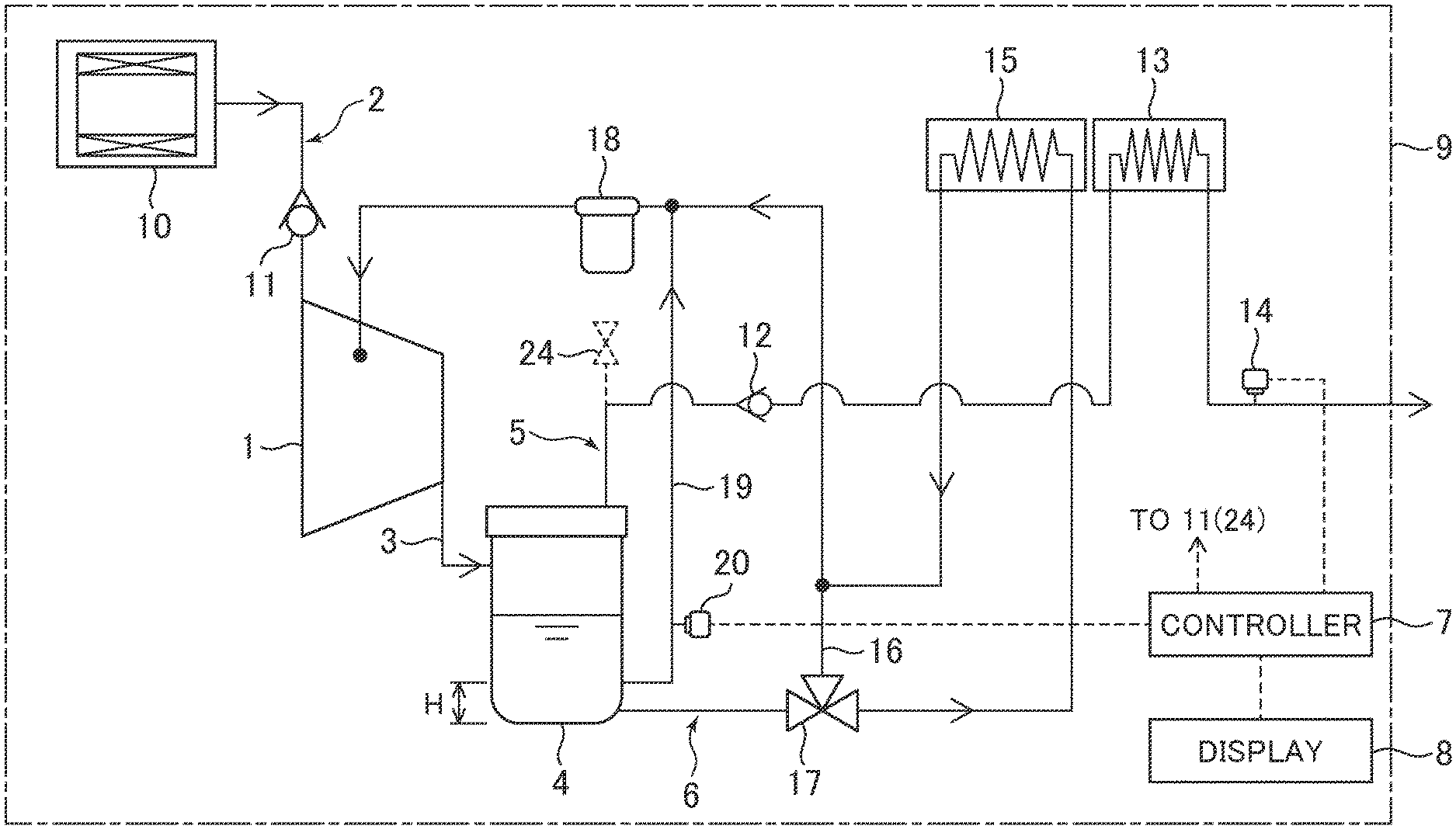
[0026] The oil-feed-type air compressor of the present embodiment includes a compressor main body 1, an intake system 2 connected to the intake side of the compressor main body 1, an oil separator 4 (gas-liquid separator) connected to the discharge side of the compressor main body 1 through a discharge line 3, a compressed air feed system 5 (compressed gas feed system) connected to the upper part of the oil separator 4, an oil feed system 6 (liquid feed system) connected between the lower part of the oil separator 4 and the compressor main body 1, a controller 7, and a display 8. These compressor main body 1, intake system 2, discharge line 3, oil separator 4, compressed air feed system 5, oil feed system 6, controller 7, and display 8 are disposed on the same pedestal (base, pallet, or air tank in the case of a tank-mounted type, or the like) to configure a compressor unit 9. In particular, in the present embodiment, the compressor unit 9 is configured with a housing composed of panel plates which surround the circumferential surface and the upper surface of the unit.
[0027] Although details are not shown in the diagram, the compressor main body 1 has a pair of male and female screw rotors that mesh with each other and a casing that houses them, and plural compression chambers are formed in the tooth spaces of the screw rotors. When the screw rotors rotate, the compression chambers move in the axial direction of the rotors. The compression chambers take in air (gas) from the intake system 2 and compress the air to discharge the compressed air (compressed gas) to the discharge line 3. The compressor main body 1 injects oil (liquid) into the compression chambers at any stage in the compression process, typified by a stage immediately after start of compression, for example, for the purpose of cooling of heat of compression, lubrication of the rotors, seal of the compression chambers, and so forth.
[0028] The intake system 2 has a suction filter 10 that removes impurities in air and a suction throttle valve 11 that is set on the downstream side of the suction filter 10 and can close the intake side of the compressor main body 1.
[0029] The oil separator 4 separates oil from the compressed air discharged from the compressor main body 1 by using specific gravity separation and impingement separation, for example, and stores the separated oil at the lower part. The compressed air separated by the oil separator 4 is fed to a use destination outside the unit through the compressed air feed system 5. The compressed air feed system 5 has a pressure regulating valve (check valve) 12, an after-cooler 13 that is disposed on the downstream side of the pressure regulating valve 12 and cools the compressed air, and a control pressure sensor 14 that is disposed on the downstream side of the pressure regulating valve 12 and detects the pressure of the compressed air (i.e. pressure that varies depending on the amount of use of the compressed air). The control pressure sensor 14 outputs the detected pressure to the controller 7.
[0030] The oil stored in the oil separator 4 is fed to the compression chambers through the oil feed system 6 by the pressure difference between the oil separator 4 and the compression chambers of the compressor main body 1. The oil feed system 6 has an oil cooler 15 that cools the oil, a bypass line 16 that bypasses the oil cooler 15, a temperature regulating valve (three-way valve) 17 set at the inlet (branch point) of the bypass line 16, and an oil filter 18 that is disposed on the downstream side relative to the outlet (merging point) of the bypass line 16 and removes impurities in the oil. The temperature regulating valve 17 detects the temperature of the oil and regulates the ratio between the flow rate on the side of the oil cooler 15 and the flow rate on the side of the bypass line 16 according to the temperature of the oil. Thereby, the temperature of the oil fed to the compressor main body 1 is regulated.
[0031] The controller 7 has an calculation control section (for example, CPU) that executes calculation processing and control processing by cooperation with a program, a storing section (for example, ROM and RAM) that stores the program and the result of the calculation processing, and so forth. As an operation control function, the controller 7 controls the opened/closed state of the suction throttle valve 11 according to the pressure detected by the control pressure sensor 14 and switches the operation state of the compressor main body 1 based on this. It is also possible for all or part of the controller 7 to have an analog circuit configuration.
[0032] Specifically, at the time of load operation of the compressor main body 1 (in other words, when the suction throttle valve 11 is in the opened state), the controller 7 determines whether the pressure detected by the control pressure sensor 14 has risen to become an unloading start pressure Pu set in advance. Then, if the pressure detected by the control pressure sensor 14 becomes the unloading start pressure Pu, the controller 7 controls the suction throttle valve 11 to the closed state to cause switching to no-load operation of the compressor main body 1.
[0033] At the time of no-load operation of the compressor main body 1 (in other words, when the suction throttle valve 11 is in the closed state), the controller 7 determines whether the pressure detected by the control pressure sensor 14 has fallen to become a load return pressure Pd (where Pd<Pu) set in advance. Then, if the pressure detected by the control pressure sensor 14 becomes the load return pressure Pd, the controller 7 controls the suction throttle valve 11 to the opened state to cause switching to load operation of the compressor main body 1. By the above operation switching, reduction in the power consumption can be intended when the amount of use of the compressed air decreases.
[0034] Here, as one of characteristics of the present embodiment, the oil-feed-type air compressor includes a sampling line 19 whose inlet side is connected to a predetermined height position H of the oil separator 4 (specifically, for example, height position of the oil surface corresponding to the desired amount of stored oil when the compressor is driven) and whose outlet side is connected to the upstream side of the oil filter 18 of the oil feed system 6, and a pressure sensor 20 (detector) that detects the pressure of fluid that flows in the sampling line 19. In the present embodiment example, the sectional area of the sampling line 19 is smaller than that of the line of the oil feed system 6, for example, so that the flow rate may become lower than that of the oil feed system 6. However, the sampling line 19 is not limited thereto. The pressure sensor 20 outputs the detected pressure to the controller 7.
[0035] As an oil surface height detection function, at the time of load operation of the compressor main body 1 (in other words, when the oil surface in the oil separator 4 is lower than that at the time of no-load operation of the compressor main body 1), the controller 7 determines which of air and oil the fluid that flows in the sampling line 19 is (or which of them mainly exists) by carrying out determination of whether the pressure detected by the pressure sensor 20 gets out of a set range set in advance in some cases (in other words, determination of whether the pressure exceeds a set value P1 set in advance in some cases and determination of whether the pressure falls below a set value P2 (where P2<P1) set in advance in some cases), and outputs the determination result to the display 8. The display 8 informs the determination result of the controller 7.
[0036] Specifically, as shown in FIG. 1, if the oil surface in the oil separator 4 is higher than the predetermined height position H (in other words, position to which the inlet side of the sampling line 19 is connected), oil flows in the sampling line 19. In this case, as shown in FIG. 3, the pressure of oil detected by the pressure sensor 20 does not involve the occurrence of pulsation and falls within the set range (in other words, equal to or lower than the set value P1 and equal to or higher than the set value P2). Thus, the controller 7 determines that the fluid that flows in the sampling line 19 is oil. Due to this, it can be detected that the oil surface in the oil separator 4 is higher than the predetermined height position H.
[0037] On the other hand, as shown in FIG. 2, if the oil surface in the oil separator 4 is lower than the predetermined height position H, air flows in the sampling line 19. In this case, as shown in FIG. 4, the pressure of air detected by the pressure sensor 20 involves the occurrence of pulsation and gets out of the set range (in other words, exceeds the set value P1 or falls below the set value P2) in some cases. Thus, the controller 7 determines that the fluid that flows in the sampling line 19 is air. Due to this, it can be detected that the oil surface in the oil separator 4 is lower than the predetermined height position H.
[0038] If the determination result that the fluid that flows in the sampling line 19 is air is input to the display 8, the display 8 displays a message of "warning: lubricating oil is insufficient" or "warning: please replenish lubricating oil," or the like, as notification information based on the determination result. Furthermore, the determination result that the fluid that flows in the sampling line 19 is oil may be input to the display 8 and the display 8 may display a message of "lubricating oil is sufficient" or the like as information based on the determination result. These informing methods may be various forms such as sound, vibration, or combination of them.
[0039] As above, the present embodiment is based on knowledge that pulsation hardly occurs in the pressure of oil when the oil (liquid) flows in the sampling line 19 whereas pulsation occurs in the pressure of air when the air (gas) flows in the sampling line 19, and it can be determined which of oil and air the fluid that flows in the sampling line 19 is (or which of them mainly exists). Due to this, the oil surface height in the oil separator 4 can be accurately monitored.
[0040] In the first embodiment, the description is made by taking as an example the case in which the controller 7 determines which of air and oil the fluid that flows in the sampling line 19 is (or which of them mainly exists) by carrying out determination of whether the pressure detected by the pressure sensor 20 gets out of the set range in some cases (in other words, both determination of whether the pressure detected by the pressure sensor 20 exceeds the set value P1 in some cases and determination of whether the pressure falls below the set value P2 in some cases). However, the present invention is not limited thereto and modifications are possible in such a range as not to depart from the gist and technical idea of the present invention.
[0041] As a first modification example, the controller 7 may determine which of air and oil the fluid that flows in the sampling line 19 is (or which of them mainly exists) by carrying out either one of determination of whether the pressure detected by the pressure sensor 20 exceeds the set value P1 in some cases and determination of whether the pressure falls below the set value P2 in some cases. Also in such a modification example, the same effects as the above description can be obtained.
[0042] As a second modification example, the controller 7 may determine which of air and oil the fluid that flows in the sampling line 19 is (or which of them mainly exists) by carrying out one or both of determination of whether the frequency at which the pressure detected by the pressure sensor 20 exceeds the set value P1 is higher than a predetermined value and determination of whether the frequency at which the pressure detected by the pressure sensor 20 falls below the set value P2 is higher than a predetermined value. Also in such a modification example, the same effects as the above description can be obtained.
[0043] As a third modification example, the controller 7 may determine which of air and oil the fluid that flows in the sampling line 19 is (or which of them mainly exists) by calculating a change rate in the pressure detected by the pressure sensor 20 (specifically, for example, change rate of the pressure obtained at every interval of the detection time of the pressure sensor 20) and carrying out one or both of determination of whether this change rate exceeds a positive set value set in advance in some cases and determination of whether the change rate falls below a negative set value set in advance in some cases. Also in such a modification example, the same effects as the above description can be obtained.
[0044] A second embodiment of the present invention will be described with reference to the drawings. In the present embodiment, the same part as the first embodiment is given the same character and description thereof is omitted as appropriate.
[0045] FIG. 5 is a schematic diagram that represents the configuration of an oil-feed-type compressor in the present embodiment. Main differences from the first embodiment in terms of the configuration are that a sampling line 19A in the second embodiment has a configuration in which the outlet side thereof is connected to the upstream side relative to the temperature regulating valve 17 on the oil feed system 6 and that the pressure sensor 20 is disposed on the downstream side relative to the outlet of the sampling line 19A (in the present embodiment, on the downstream side relative to the outlet of the bypass line 16) on the oil feed system 6. In other words, one of characteristics of the second embodiment is that not pressure pulsation of the sampling line 19A but pressure pulsation that occurs in the oil feed system 6 due to the sampling line 19A is detected.
[0046] Specifically, for example, when the compressor is in load operation, if the oil surface position in the oil separator 4 becomes lower than the position of the inlet side of the sampling line 19A, air flows to the oil feed system 6 through the sampling line 19A similarly to the first embodiment. In other words, air or oil or mixed fluid of them flows to the bypass line 16 and pressure pulsation occurs. Change in this pulsation is detected by the pressure sensor 20 and the controller can detect the height of the oil surface similarly to the first embodiment.
[0047] As long as the pressure sensor 20 exists on the downstream side relative to the outlet-side connecting part of the sampling line 19A on the oil feed system 6, a configuration in which the connection configuration of the sampling line 19A is made same as the first embodiment may be employed.
[0048] Also in such a second embodiment, the same effects as the first embodiment and the modification examples thereof can be obtained. In particular, in the present embodiment, the size of the sampling line 19A is small and it is also possible to expect effects of simplification of the line configuration and reduction in the member cost.
[0049] A third embodiment of the present invention will be described with reference to the drawings. In the present embodiment, the same part as the first or second embodiment is given the same character and description thereof is omitted as appropriate.
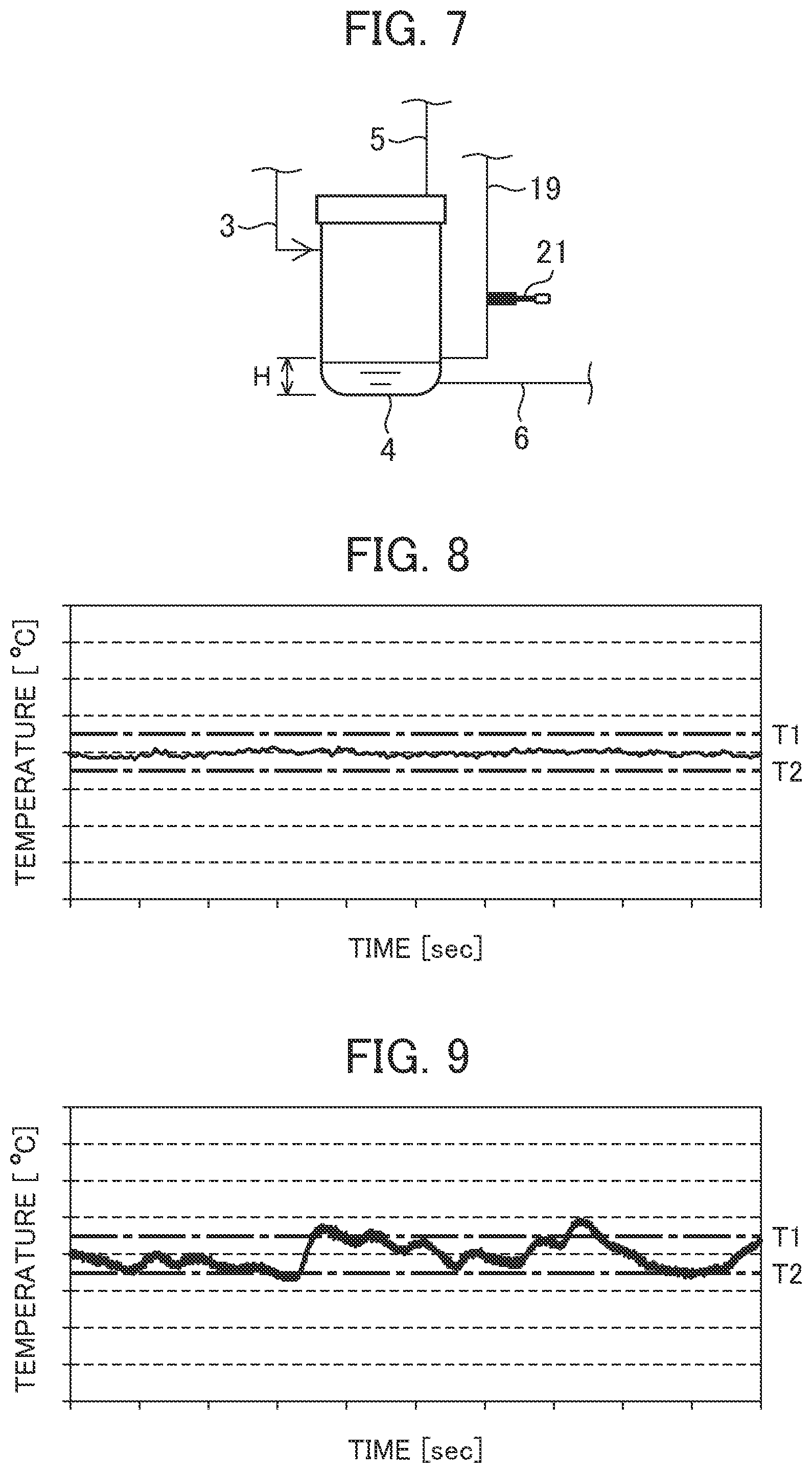
[0050] FIG. 6 is a schematic diagram that represents the configuration of an oil-feed-type air compressor in the present embodiment and shows the state in which the amount of stored oil in the oil separator 4 is sufficient. FIG. 7 is a diagram showing the state in which the amount of stored oil in the oil separator 4 is insufficient in the present embodiment.
[0051] The oil-feed-type air compressor of the present embodiment includes, instead of the pressure sensor 20, a temperature sensor 21 (detector) that detects the temperature of fluid that flows in the sampling line 19. The temperature sensor 21 outputs the detected temperature to a controller 7A.
[0052] As an oil surface height detection function, at the time of load operation of the compressor main body 1, the controller 7A determines which of air and oil the fluid that flows in the sampling line 19 is by carrying out determination of whether the temperature detected by the temperature sensor 21 gets out of a set range set in advance in some cases (in other words, both determination of whether the temperature exceeds a set value T1 set in advance in some cases and determination of whether the temperature falls below a set value T2 (where T2<T1) set in advance in some cases), and outputs the determination result to the display 8.
[0053] Specifically, as shown in FIG. 6, if the oil surface in the oil separator 4 is higher than the predetermined height position H, oil flows in the sampling line 19. In this case, as shown in FIG. 8, the temperature of oil detected by the temperature sensor 21 does not involve the occurrence of pulsation and falls within the set range (in other words, equal to or lower than the set value T1 and equal to or higher than the set value T2). Thus, the controller 7A determines that the fluid that flows in the sampling line 19 is oil. Due to this, it can be detected that the oil surface in the oil separator 4 is higher than the predetermined height position H.
[0054] On the other hand, as shown in FIG. 7, if the oil surface in the oil separator 4 is lower than the predetermined height position H, air flows in the sampling line 19. In this case, as shown in FIG. 9, the temperature of air detected by the temperature sensor 21 involves the occurrence of pulsation and gets out of the set range (in other words, exceeds the set value T1 or falls below the set value T2) in some cases. Thus, the controller 7A determines that the fluid that flows in the sampling line 19 is air. Due to this, it can be detected that the oil surface in the oil separator 4 is lower than the predetermined height position H.
[0055] If the determination result that the fluid that flows in the sampling line 19 is air is input to the display 8, the display 8 displays a message of "warning: lubricating oil is insufficient" or "warning: please replenish lubricating oil," or the like, as information based on the determination result. Furthermore, the determination result that the fluid that flows in the sampling line 19 is oil may be input to the display 8 and the display 8 may display a message of "lubricating oil is sufficient" or the like as information based on the determination result.
[0056] As above, the present embodiment is based on knowledge that pulsation hardly occurs in the temperature of oil when the oil (liquid) is caused to flow in the sampling line 19 whereas pulsation occurs in the temperature of air when the air (gas) is caused to flow in the sampling line 19, and it can be determined which of oil and air the fluid that flows in the sampling line 19 is (or which of them mainly exists). Due to this, the oil surface height in the oil separator 4 can be monitored.
[0057] In the third embodiment, the description is made by taking as an example the case in which the controller 7A determines which of air and oil the fluid that flows in the sampling line 19 is (or which of them mainly exists) by carrying out determination of whether the temperature detected by the temperature sensor 21 gets out of the set range in some cases (in other words, both determination of whether the temperature detected by the temperature sensor 21 exceeds the set value T1 in some cases and determination of whether the temperature falls below the set value T2 in some cases). However, the present invention is not limited thereto and modifications are possible in such a range as not to depart from the gist and technical idea of the present invention.
[0058] As a fourth modification example, the controller 7A may determine which of air and oil the fluid that flows in the sampling line 19 is (or which of them mainly exists) by carrying out either one of determination of whether the temperature detected by the temperature sensor 21 exceeds the set value T1 in some cases and determination of whether the temperature falls below the set value T2 in some cases. Also in such a modification example, the same effects as the above description can be obtained.
[0059] As a fifth modification example, the controller 7A may determine which of air and oil the fluid that flows in the sampling line 19 is (or which of them mainly exists) by carrying out one or both of determination of whether the frequency at which the temperature detected by the temperature sensor 21 exceeds the set value T1 is higher than a predetermined value and determination of whether the frequency at which the temperature detected by the temperature sensor 21 falls below the set value T2 is higher than a predetermined value. Also in such a modification example, the same effects as the above description can be obtained.
[0060] As a sixth modification example, the controller 7A may determine which of air and oil the fluid that flows in the sampling line 19 is (or which of them mainly exists) by calculating a change rate in the temperature detected by the temperature sensor 21 (specifically, for example, change rate of the temperature obtained at every interval of the detection time of the temperature sensor 21) and carrying out one or both of determination of whether this change rate exceeds a positive set value set in advance in some cases and determination of whether the change rate falls below a negative set value set in advance in some cases. Also in such a modification example, the same effects as the above description can be obtained.
[0061] Naturally it is also possible to apply the configuration of the second embodiment (FIG. 5) to the third embodiment. In other words, the same effects as the third embodiment can be obtained also when the pressure sensor 20 according to the second embodiment is replaced by the temperature sensor 21 according to the third embodiment.
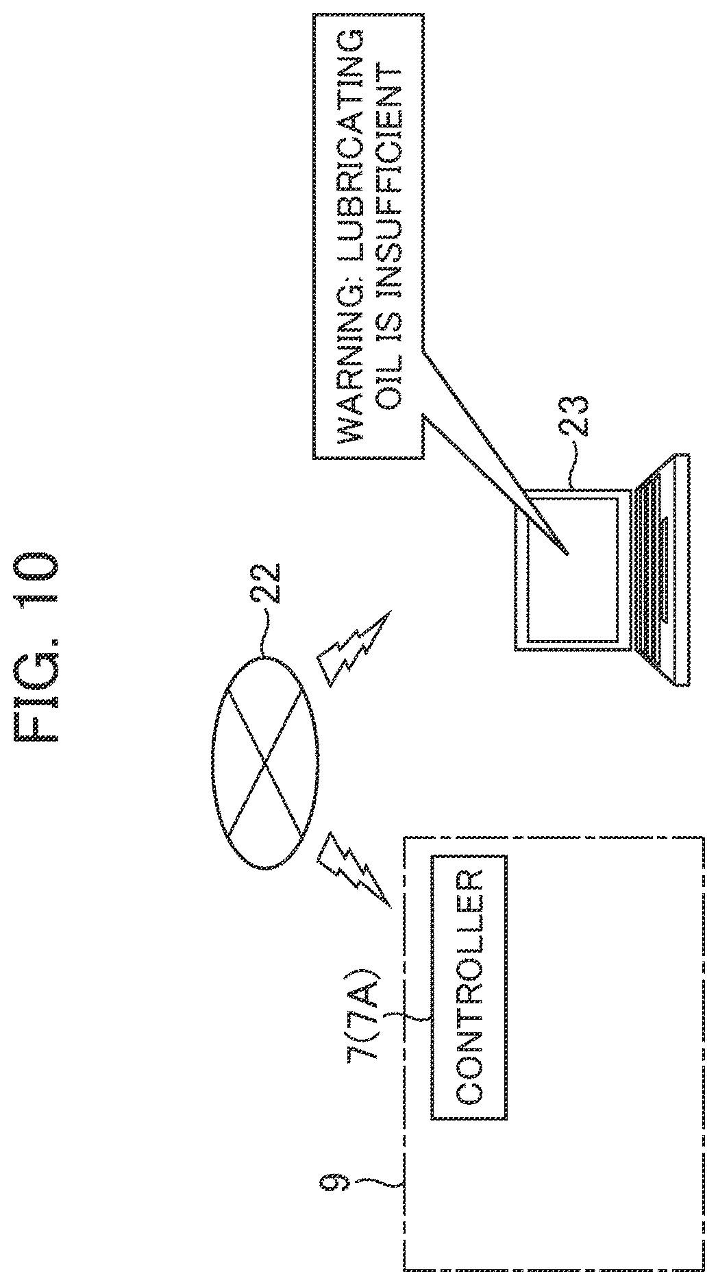
[0062] Furthermore, in the first to third embodiments and the above-described modification examples, the description is made by taking as an example the case in which the informing device that informs the determination result of the controller 7 or 7A is the display 8 that is mounted on the compressor unit 9 and displays information based on the determination result of the controller 7 or 7A. However, the present invention is not limited thereto and modifications are possible in such a range as not to depart from the gist and technical idea of the present invention. As in a seventh modification example shown in FIG. 10, the informing device may be, for example, a communication terminal 23 that is separated from the compressor unit 9 and displays information (specifically, a message of, for example, "warning: lubricating oil is insufficient" or "warning: please replenish lubricating oil," or the like) based on the determination result of the controller 7 or 7A received through a communication channel 22. The communication terminal 23 may be a configuration physically in contact with the compressor unit 9 as long as it is a separated configuration as the configuration of communication connection. For example, a configuration may be employed in which the communication terminal 23 is placed or suspended at any place in the compressor unit 9 and is temporarily fixed in such a manner as to be separatable.
[0063] Furthermore, as another configuration that uses the communication channel shown in FIG. 10, a configuration may be employed in which an external calculator (server or the like) connected through the communication channel 22 is equipped with the determination function of the controller 7 or 7A and the determination result thereof is informed from the external calculator to the communication terminal 23 through the communication channel 22. Moreover, a configuration in which the communication terminal 23 has the determination function of the controller 7 or 7A may be employed.
[0064] Although not shown in the diagram, the informing device may be a warning lamp or warning buzzer mounted on the compressor unit 9, for example. Furthermore, the controller 7 or 7A may drive the warning lamp or warning buzzer when determining that the fluid that flows in the sampling line 19 is air. Also in these modification examples, the same effects as the above description can be obtained.
[0065] Furthermore, in the first to third embodiments, the description is made by taking as an example the case in which the outlet side of the sampling line 19 (19A) is connected to the upstream side of the oil filter 18 of the oil feed system 6. However, the present invention is not limited thereto and modifications are possible in such a range as not to depart from the gist and technical idea of the present invention. In other words, it suffices that the sampling line is configured in such a manner that the inlet side is connected to the predetermined height position of the oil separator 4 and the fluid from the predetermined height position of the oil separator 4 is allowed to flow by the pressure difference between the inlet side (higher pressure side) and the outlet side (lower pressure side). For this reason, it suffices that the pressure at the site to which the outlet side of the sampling line is connected is lower than the pressure in the oil separator 4 by at least the pressure loss of the sampling line.
[0066] Moreover, in the first to third embodiments, the description is made by taking as an example the case in which, in the oil-feed-type air compressor, the suction throttle valve 11 that closes the intake side of the compressor main body 1 is set in order to switch the compressor main body 1 from load operation to no-load operation. However, the present invention is not limited thereto and modifications are possible in such a range as not to depart from the gist and technical idea of the present invention.
[0067] The oil-feed-type air compressor may include a relief valve 24 (shown by a dotted line in FIG. 1, FIG. 5, or FIG. 6) that releases a gas on the discharge side of the compressor main body 1 (specifically, upstream side relative to the pressure regulating valve 12 of the compressed air feed system 5) instead of the suction throttle valve 11 in order to switch the compressor main body 1 from load operation to no-load operation. Furthermore, if the pressure detected by the control pressure sensor 14 becomes the unloading start pressure Pu, the controller 7 or 7A controls the relief valve 24 to the opened state to switch the compressor main body 1 from load operation to no-load operation. Moreover, if the pressure detected by the control pressure sensor 14 becomes the load return pressure Pd, the controller 7 or 7A controls the relief valve 24 to the closed state to switch the compressor main body 1 from no-load operation to load operation.
[0068] Alternatively, the oil-feed-type air compressor may include both the suction throttle valve 11 and the relief valve 24. Furthermore, the oil-feed-type air compressor may be configured in such a manner as not to switch the compressor main body 1 from load operation to no-load operation. In other words, the oil-feed-type air compressor may not include the suction throttle valve 11 or the relief valve 24 and the controller 7 or 7A may not include the above-described operation control function. Also in these modification examples, the same effects as the above description can be obtained.
[0069] In the above, the description is made by taking as an example the case in which the present invention is applied to the oil-feed-type air compressor. However, the present invention is not limited thereto. For example, the present invention may be applied to a water-feed-type air compressor including a compressor main body that compresses air (gas) while injecting water (liquid) into compression chambers, a water separator (gas-liquid separator) that separates the water from the compressed air (compressed gas) discharged from the compressor main body and stores the water therein, and a water feed system (liquid feed system) that feeds the water stored in the water separator to the compressor main body. If the present invention is applied to this water-feed-type air compressor, the water surface height in the water separator can be monitored. Furthermore, the present invention may be applied to a compressor that compresses a gas other than air.
[0070] Moreover, in the above, the description is made by taking as an example the compression mechanism of a so-called twin-screw rotor composed of male and female screw rotors. However, the present invention is not limited thereto. For example, it is also possible to apply various compression mechanisms such as positive displacement type and turbo type. The positive displacement type includes rotary type, reciprocating type, and so forth. As the rotary type, single screw rotor, twin screw rotor, and multi screw rotor, single scroll lap and multi scroll lap, vane type, craw type, and so forth are included. As the reciprocating type, single reciprocating type and multi reciprocating type and so forth are included. Moreover, the compressor main body is also not limited to the one-compressor configuration and even a multi-stage configuration formed of a combination based on the same forms or different forms can be applied.
DESCRIPTION OF REFERENCE CHARACTERS
[0071] 1: Compressor main body [0072] 4: Oil separator (gas-liquid separator) [0073] 6: Oil feed system (liquid feed system) [0074] 7, 7A: Controller [0075] 8: Display (informing device) [0076] 9: Compressor unit [0077] 11: Suction throttle valve [0078] 19, 19A: Sampling line [0079] 20: Pressure sensor (detector) [0080] 21: Temperature sensor (detector) [0081] 22: Communication channel [0082] 23: Communication terminal (informing device) [0083] 24: Relief valve
* * * * *
D00000
D00001
D00002
D00003
D00004
D00005
D00006
XML
uspto.report is an independent third-party trademark research tool that is not affiliated, endorsed, or sponsored by the United States Patent and Trademark Office (USPTO) or any other governmental organization. The information provided by uspto.report is based on publicly available data at the time of writing and is intended for informational purposes only.
While we strive to provide accurate and up-to-date information, we do not guarantee the accuracy, completeness, reliability, or suitability of the information displayed on this site. The use of this site is at your own risk. Any reliance you place on such information is therefore strictly at your own risk.
All official trademark data, including owner information, should be verified by visiting the official USPTO website at www.uspto.gov. This site is not intended to replace professional legal advice and should not be used as a substitute for consulting with a legal professional who is knowledgeable about trademark law.