Drop Balls for Use with Settable Downhole Tools
Frazier; Warren Lynn ; et al.
U.S. patent application number 16/591499 was filed with the patent office on 2020-04-02 for drop balls for use with settable downhole tools. The applicant listed for this patent is Nine Downhole Technologies, LLC. Invention is credited to Warren Lynn Frazier, Donald Roy Greenlee, Brian David Oligschlaeger.
| Application Number | 20200102804 16/591499 |
| Document ID | / |
| Family ID | 69947233 |
| Filed Date | 2020-04-02 |


View All Diagrams
| United States Patent Application | 20200102804 |
| Kind Code | A1 |
| Frazier; Warren Lynn ; et al. | April 2, 2020 |
Drop Balls for Use with Settable Downhole Tools
Abstract
Aspects of the present disclosed technology relate to drop balls and covers for drop balls for use with settable downhole tools. Aspects of the present disclosed technology also relate to methods for using such drop balls and covers with settable downhole tools to selectively allow fluid to pass through such downhole tools, or to block fluid flow through the settable downhole tool.
| Inventors: | Frazier; Warren Lynn; (Corpus Christi, TX) ; Greenlee; Donald Roy; (Murchison, TX) ; Oligschlaeger; Brian David; (Aledo, TX) | ||||||||||
| Applicant: |
|
||||||||||
|---|---|---|---|---|---|---|---|---|---|---|---|
| Family ID: | 69947233 | ||||||||||
| Appl. No.: | 16/591499 | ||||||||||
| Filed: | October 2, 2019 |
Related U.S. Patent Documents
| Application Number | Filing Date | Patent Number | ||
|---|---|---|---|---|
| 62740173 | Oct 2, 2018 | |||
| Current U.S. Class: | 1/1 |
| Current CPC Class: | E21B 23/0413 20200501; E21B 33/12 20130101 |
| International Class: | E21B 33/12 20060101 E21B033/12 |
Claims
1. A cage for use with a drop ball for a settable downhole tool, the cage comprising: a spherical pocket surrounded by a plurality of deformable segments of material, wherein the plurality of deformable segments are arranged into a plurality of rings.
2. The cage of claim 1, wherein the deformable segments have a durometer in the range of Shore A 60 to 100.
3. The cage of claim 1, wherein the spherical pocket has a diameter between about 0.75 inches and about 4.375 inches.
4. The cage of claim 1, wherein the plurality of deformable segments are arranged to form three mutually orthogonal rings around the spherical pocket.
5. The cage of claim 1, wherein the plurality of deformable segments comprise a dissolvable material.
6. A drop ball for use with a settable downhole tool, the drop ball comprising: a spherical body surrounded by a plurality of deformable segments of material, wherein the plurality of deformable segments are arranged into a plurality of rings.
7. The drop ball of claim 6, wherein the deformable segments have a durometer in the range of Shore A 60 to 100.
8. The drop ball of claim 6, wherein the spherical pocket has a diameter between about 0.75 inches and about 4.375 inches.
9. The drop ball of claim 6, wherein the plurality of deformable segments are arranged to form three mutually orthogonal rings around the spherical pocket.
10. The drop ball of claim 6, wherein the spherical body is made of a first material, the deformable segments are made of a second material different than the first material, and the deformable segments are overmolded on the spherical body.
11. The drop ball of claim 6, wherein the deformable segments have a durometer in the range of Shore A 60 to 100.
12. The drop ball of claim 6, wherein the spherical body is comprised of a polymer acid.
13. The drop ball of claim 6, wherein the spherical body is comprised of a first dissolvable material having a first dissolution rate, and the plurality of deformable segments are comprised of a second dissolvable material having a second dissolution rate.
14. The drop ball of claim 13, wherein the second dissolution rate is faster than the first dissolution rate.
15. A method for using a drop ball with a settable downhole tool, the method comprising: placing a drop ball on a seat located on an inner fluid channel of a settable downhole tool in a wellbore, wherein the drop ball comprises: a spherical body surrounded by a plurality of deformable segments of material, wherein each of the deformable segments have a height measured from a boundary of the pocket to a point on the segment having a maximum radial distance from a center of the pocket, and wherein an outer diameter of the drop ball including the deformable segments is greater than the seat; and pumping a fluid through a wellbore at a first flow rate, wherein the fluid passes around the drop ball and through the inner channel of the downhole tool; and pumping a fluid through a wellbore at a second flow rate, wherein the second flow rate is greater than the first flow rate, and wherein the deformable segments of material deform and a fluid-tight seal is formed between the seat and the drop ball, preventing a fluid flow through the inner channel of the settable downhole tool.
16. The method of claim 15, wherein the deformable segments have a durometer in the range of Shore A 60 to 100.
17. The method of claim 15, wherein the spherical pocket has a diameter between about 0.75 inches and about 4.375 inches.
18. The method of claim 15, wherein the plurality of deformable segments are arranged to form three mutually orthogonal rings around the spherical pocket.
19. The method of claim 15, wherein the spherical body is made of a first material, the deformable segments are made of a second material different than the first material, and the deformable segments are overmolded on the spherical body.
20. The method of claim 15, wherein the first flow rate is less than about 20 barrels per minute.
Description
CROSS-REFERENCE TO RELATED APPLICATION
[0001] This application claims the benefit of U.S. Provisional Application No. 62/740,173, entitled "CONFIGURED DROP BALLS FOR USE WITH SETTABLE DOWNHOLE TOOLS", filed 2 Oct. 2018.
TECHNICAL FIELD
[0002] Aspects of the present disclosed technology relate to drop balls and covers for drop balls for use with settable downhole tools. Aspects of the present disclosed technology also relate to methods for using such drop balls and covers with settable downhole tools to selectively allow fluid to pass through such downhole tools, or to block fluid flow through the settable downhole tool.
BACKGROUND OF THE INVENTION
[0003] Oil well completion operations frequently involve downhole tools with explosive elements, such as perforating guns ("perf guns" or "frac guns"). Examples of such operations include formation perforation prior to hydraulic fracturing, where frac guns are used to perforate oil well casing and/or perforate the surrounding geological formation. Perforating is typically performed in a series of stages, where each stage is a portion of the well that is isolated using frac plugs or similar tools. In some forms of frac plugs, each plug has a hole through the plug, and a seat that is capable of receiving a ball that seals the frac plug. These plugs are set downhole, and then frac balls can be run downhole (or released from the setting tool), which seat themselves in the frac plug, forming a seal capable of holding pressure.
[0004] Occasionally, frac guns will fail to fire. When this occurs, the frac guns typically have to be removed from the hole, repaired or replaced and re-run back into the well. Running the frac guns back down the hole often requires pumping a fluid down the wellbore, which pushes the frac guns back down to the intended area of the wellbore. If a ball is already seated in the plug, it can be difficult, if not impossible, to re-run the repaired or replaced frac guns back down the wellbore. Attempts to pump the tools down will be hindered by the pressure seal formed by the ball seated in the frac plug.
[0005] Accordingly, it would be advantageous to have a drop ball in place on a settable tool which can selectively either seal the plug against fluid flow through the plug or permit fluid to be pumped around the ball and through the plug seat. This feature would allow frac guns or other downhole tools to be pumped down the wellbore even after a drop ball has been placed on the settable downhole tool. It would also be advantageous to have the same ball, which can selectively either seal the plug against fluid flow through the plug or permit fluid to be pumped around the ball and through the plug seat during pumping down of guns, adapted to seal (hold pressure) against the set tool seat during fracking or other high pressure/high flow operations. Aspects of the present disclosure accomplish these purposes, among others.
[0006] Some embodiments comprise a rubber or elastomeric overmolded composite frac ball. In these embodiments, the cover can be an overmolded material having multiple spikes, similar to a pet or child's rubber spiked ball. In some embodiments, the overmold can comprise one or more deformable segments that surround the composite frac ball, such as in rings or other similar configurations. The rubber or elastomer can have a durometer in the range of Shore A 60 to 100, or preferably in the range of Shore A of 85 to 95, including in some embodiments, a Shore A about 90 durometer, that is hard enough to maintain the ball in a standoff position from the ball seat (low psi, gun removal/insertion) except during higher or high psi on the ball from above the tool, such as is encountered by the ball during a fracking operation or high pump rates. In this condition, the spikes or deformable segments in contact with the plug's ball seat will deform, break or collapse responsive to the downward pressure on the ball, and the downward pressure on the ball will push it toward the seal, causing the ball to seal against the seat, and at least partly seal the plug, so the plug will then hold pressure in the frac zone above the plug during a fracking operation. Thus, a system and configuration for a tool is created such that in the event that frac guns do not fire, one can pull the guns out of the hole and pump good guns back down at a slower rate or psi while being able to flow around the spiked ball and through the plug, and still have a good seal between the ball and the plug at a higher fracking pressure or psi pump rates.
SUMMARY OF THE INVENTION
[0007] Aspects of the present disclosed technology relate to a cage for use with a drop ball for a settable downhole tool, the cage comprising: a spherical pocket surrounded by a plurality of deformable segments of material, wherein the plurality of deformable segments are arranged into a plurality of rings. In some embodiments, the deformable segments have a durometer in the range of Shore A 60 to 100. In some embodiments, the spherical pocket has a diameter between about 0.75 inches and about 4.375 inches. In some embodiments, the plurality of deformable segments are arranged to form three mutually orthogonal rings around the spherical pocket. In some embodiments, the plurality of deformable segments comprise a dissolvable material.
[0008] Aspects of the present disclosed technology also relate to a drop ball for use with a settable downhole tool, the drop ball comprising: a spherical body surrounded by a plurality of deformable segments of material, wherein the plurality of deformable segments are arranged into a plurality of rings. In some embodiments, the deformable segments have a durometer in the range of Shore A 60 to 100. In some embodiments, the spherical pocket has a diameter between about 0.75 inches and about 4.375 inches. In some embodiments, the plurality of deformable segments are arranged to form three mutually orthogonal rings around the spherical pocket. In some embodiments, the spherical body is made of a first material, the deformable segments are made of a second material different than the first material, and the deformable segments are overmolded on the spherical body. In some embodiments, the deformable segments have a durometer in the range of Shore A 60 to 100. In some embodiments, the spherical body comprises a polymer acid. In some embodiments, the spherical body comprises a first dissolvable material having a first dissolution rate, and the plurality of deformable segments comprise a second dissolvable material having a second dissolution rate. In some embodiments, the second dissolution rate is faster than the first dissolution rate.
[0009] Aspects of the present disclosed technology also relate to a method for using a drop ball with a settable downhole tool, the method comprising: placing a drop ball on a seat located on an inner fluid channel of a settable downhole tool in a wellbore, wherein the drop ball comprises: a spherical body surrounded by a plurality of deformable segments of material, wherein each of the deformable segments have a height measured from a boundary of the pocket to a point on the segment having a maximum radial distance from a center of the pocket, and, wherein an outer diameter of the drop ball including the deformable segments is greater than the ball seat; and pumping a fluid through a wellbore at a first flow rate, wherein the fluid passes around the drop ball and through the inner channel of the downhole tool; and pumping a fluid through a wellbore at a second flow rate, wherein the second flow rate is greater than the first flow rate, and wherein the deformable segments of material deform and a fluid-tight seal is formed between the seat and the drop ball, preventing a fluid flow through the inner channel of the settable downhole tool. In some embodiments, the deformable segments have a durometer in the range of Shore A 60 to 100. In some embodiments, the spherical pocket has a diameter between about 0.75 inches and about 4.375 inches. In some embodiments, the plurality of deformable segments are arranged to form three mutually orthogonal rings around the spherical pocket. In some embodiments, the spherical body is made of a first material, the deformable segments are made of a second material different than the first material, and the deformable segments are overmolded on the spherical body. In some embodiments, the first flow rate is less than about 20 barrels per minute.
BRIEF DESCRIPTION OF THE DRAWINGS
[0010] Included in the present specification are figures which illustrate various embodiments of the present disclosed technology. As will be recognized by a person of ordinary skill in the art, actual embodiments of the disclosed technology need not incorporate each and every component illustrated, but can omit components, add additional components, or change the general order and placement of components. Reference will now be made to the accompanying figures and flow diagrams, which are not necessarily drawn to scale, and wherein:
[0011] FIG. 1 illustrates a drop ball in accordance with an embodiment.
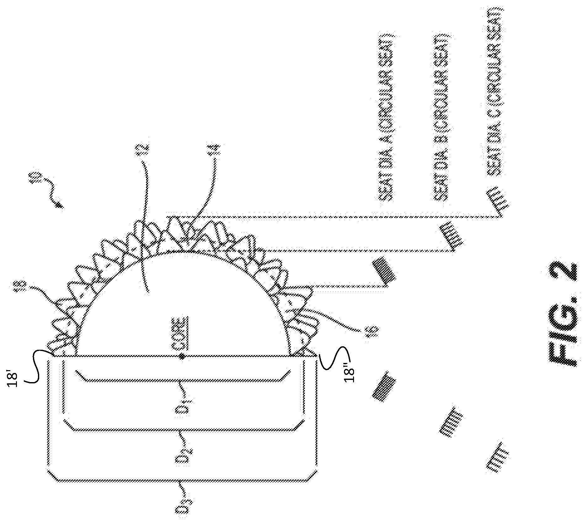
[0012] FIG. 2 illustrates a cutaway view of a drop ball in accordance with an embodiment that illustrates the interaction of the drop ball with ball seats of various diameters.
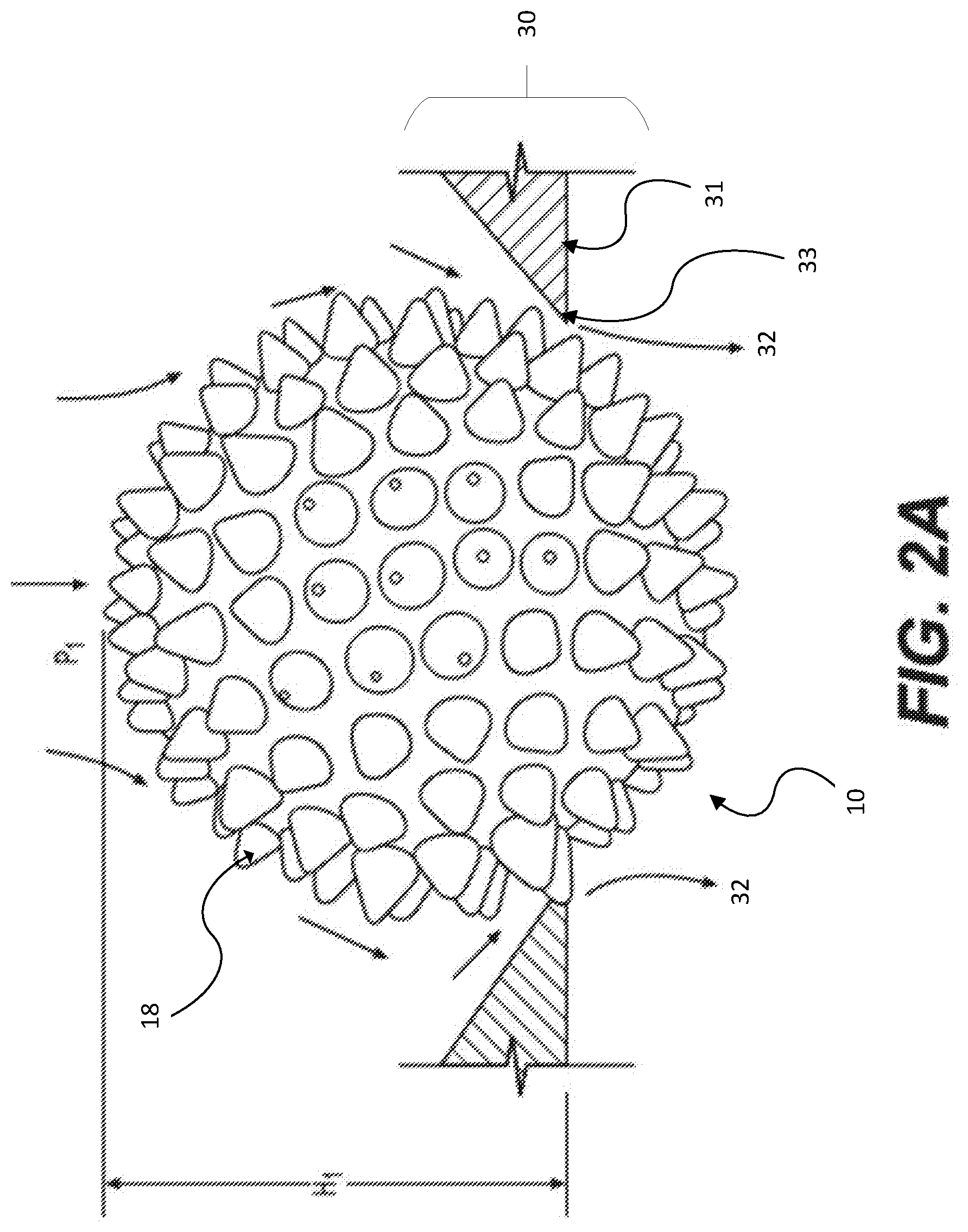
[0013] FIG. 2A illustrates a drop ball in accordance with an embodiment located in a seat, where the spikes of the drop ball provide a "stand-off" space allowing fluid to flow around the ball and through the ball seat.
[0014] FIG. 2B illustrates a drop ball in accordance with an embodiment located in a seat, where the spikes of the drop ball are compressed, forming a fluid seal with the ball seat.
[0015] FIG. 3 illustrates a spike on a drop ball in accordance with an embodiment.
[0016] FIG. 4 illustrates a drop ball in accordance with an embodiment made of a single material.
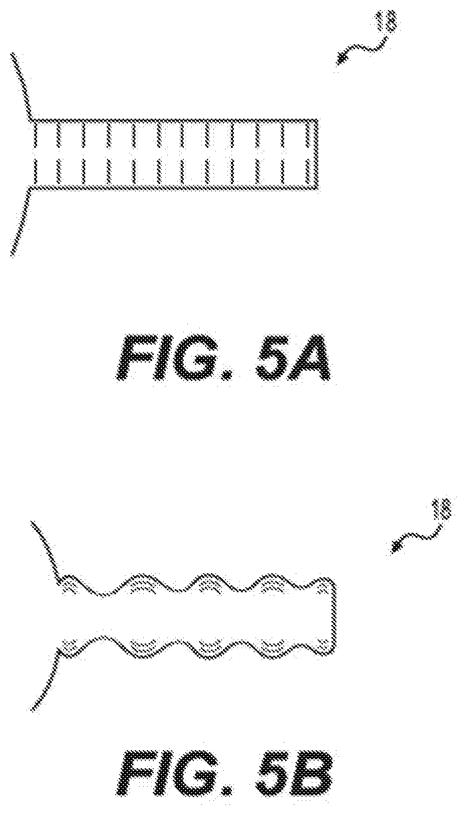
[0017] FIG. 5A illustrates a spike in accordance with an embodiment.
[0018] FIG. 5B illustrates a spike in accordance with an embodiment.
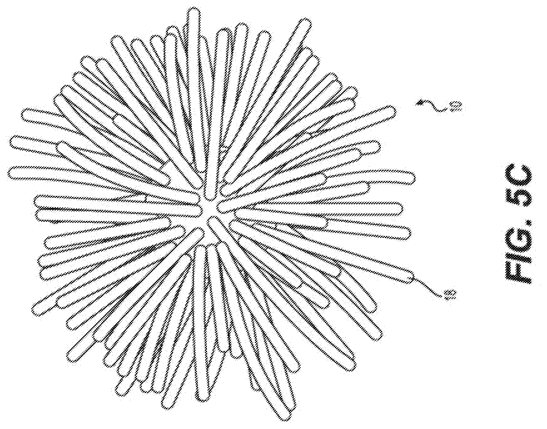
[0019] FIG. 5C illustrates a drop ball in accordance with an embodiment with long spikes.
[0020] FIG. 5D illustrates a drop ball in accordance with an embodiment with short spikes.
[0021] FIG. 5E illustrates a drop ball in accordance with an embodiment that does not have a spherical center core.
[0022] FIG. 6A illustrates a drop ball in accordance with an embodiment that does not have a spherical center core.
[0023] FIG. 6B illustrates a drop ball in accordance with an embodiment having an overmolded layer over a drop ball that does not have a spherical center core.
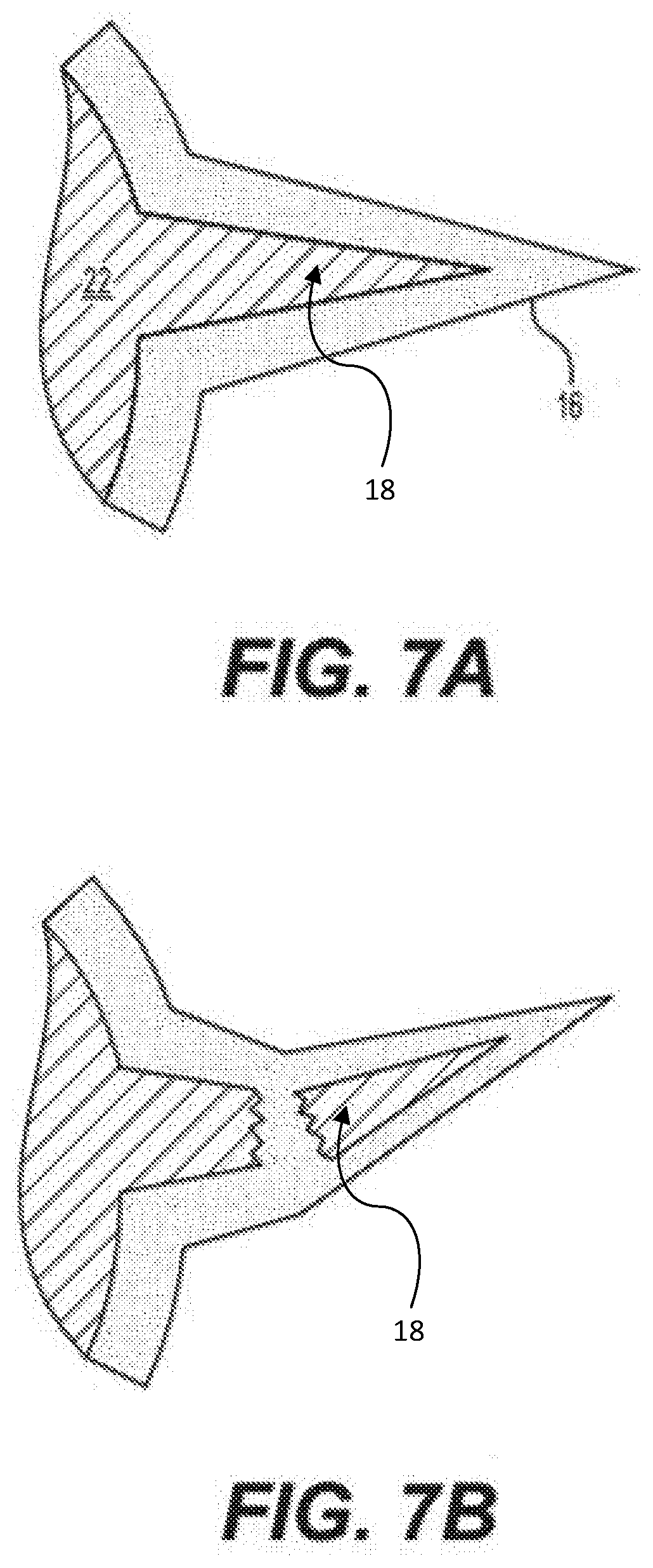
[0024] FIG. 7A illustrates an overmolded spike in accordance with an embodiment.
[0025] FIG. 7B illustrates an overmolded spike in accordance with an embodiment where the inner spike has broken.
[0026] FIG. 8 illustrates a drop ball in accordance with an embodiment having a cage.
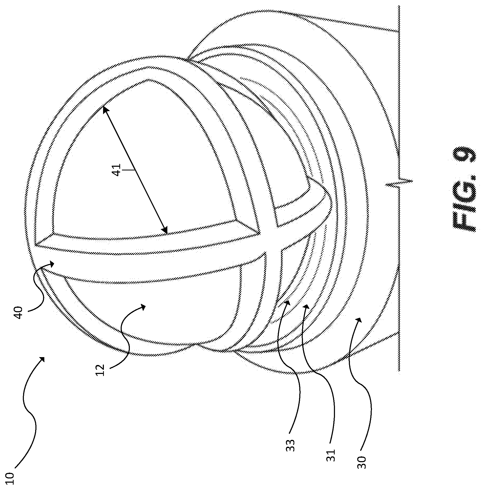
[0027] FIG. 9 illustrates a drop ball in accordance with an embodiment having a cage located on a ball seat of a settable downhole tool.
DETAILED DESCRIPTION OF THE PREFERRED EMBODIMENT
[0028] Although example embodiments of the present disclosure are explained in detail, it is to be understood that other embodiments are contemplated. Accordingly, it is not intended that the present disclosure be limited in its scope to the details of construction and arrangement of components set forth in the following description or illustrated in the drawings. The present disclosure is capable of other embodiments and of being practiced or carried out in various ways.
[0029] The terminology used herein is for the purpose of describing particular embodiments only and is not intended to be limiting of the invention. As used herein, the singular forms "a", "an" and "the" are intended to include the plural forms as well, unless the context clearly indicates otherwise. It will be further understood that the terms "comprises" and/or "comprising," when used in this specification, specify the presence of stated features, integers, steps, operations, elements, and/or components, but do not preclude the presence or addition of one more other features, integers, steps, operations, element components, and/or groups thereof.
[0030] By "comprising" or "containing" or "including" is meant that at least the named compound, element, particle, or method step is present in the composition or article or method, but does not exclude the presence of other compounds, materials, particles, method steps, even if the other such compounds, material, particles, method steps have the same function as what is named.
[0031] In describing example embodiments, terminology will be resorted to for the sake of clarity. It is intended that each term contemplates its broadest meaning as understood by those skilled in the art and includes all technical equivalents that operate in a similar manner to accomplish a similar purpose.
[0032] It is to be understood that the mention of one or more steps of a method does not preclude the presence of additional method steps or intervening method steps between those steps expressly identified. Steps of a method can be performed in a different order than those described herein. Similarly, it is also to be understood that the mention of one or more components in a device or system does not preclude the presence of additional components or intervening components between those components expressly identified.
[0033] In the following detailed description, references are made to the accompanying drawings that form a part hereof and that show, by way of illustration, specific embodiments or examples. In referring to the drawings, like numerals represent like elements throughout the several figures.
[0034] FIG. 1 illustrates a drop ball 10 in accordance with an embodiment. In some embodiments, the drop ball 10 comprises a spherical core 12 with a cover having one or more protrusions from the core. For example, FIG. 1 depicts an embodiment where the drop ball 10 has a spherical core 12 and a cover having spikes 18 which protrude from the core 12.
[0035] FIG. 2. illustrates a cutaway view of a drop ball in accordance with an embodiment that illustrates the interaction of the drop ball with ball seats of various diameters. In some embodiments, the cover 18 can be layered or molded as an overmold member 14. In some embodiments, the cover 18 can be formed separately from the core 12, and can be placed on, or removed from core 12. In some embodiments, overmold member 14 can include a spherical shell 16, having a diameter greater than the core 12 and typically layered or adhering directly against the outer surface of the core 12. In some embodiments, overmold member 14 can include a multiplicity of spikes 18, extending outward from the spherical shell 16. In some embodiments, overmolded member 14 can include a plurality of deformable segments of material. In some embodiments, the overmolded member 14 can be comprised of the same material as spherical shell 16. In some embodiments, overmold member 14 can have gaps or spaces where the core 12 is exposed to the surroundings. FIGS. 8-9 illustrate an embodiment having gaps or spaces 41, which form a cage 40 around core 12. In some embodiments, such gaps 41 can allow the overmolded member 14 or a cage 40 to be removed from the core 12, or can allow an overmolded member 14 or a cage 40 formed separately to be placed around the core 12. In some embodiments, the spherical shell 16 and/or the overmolded member 14 and/or cage 40 can comprise an elastomer, such as Nitrile, urethane rubber, TPE or rubber in some embodiments having a durometer in the range of 60 to 100 Shore A.
[0036] In some embodiments, core 12 and/or the cover 18 can comprise a degradable or non-degradable material or any number of known downhole tool composites comprising a resin and a cloth. In some embodiments, components can be comprised of a polymer acid, which optionally can be degradable in downhole fluids. In some embodiments, the core 12 can comprise a material that degrades at a rate slower than the cover 18. For those embodiments, when the cover 18 dissolves or degrades, the drop ball 10 behaves as an ordinary spherical drop ball. In some embodiments, the polymer acid can be selected from the group comprising polyglycolic acid or polylactic acid. In some embodiments, core 12 can have a diameter of D1, which can be in the range of 0.75'' to 4.375''. In some embodiments, the core 12 can be rigid and harder than overmolded member 14.
[0037] In some embodiments, overmold member 14 can be overmolded onto core 12. An example of a method for overmolding in accordance with embodiments include those described in U.S. Application 62/625,099, entitled "Molded Degradable Downhole Tool Elements," published as U.S. 2019/0169953 A1 on Jun. 6, 2019, which publication is hereby incorporated by reference in its entirety as if fully set forth herein. In some embodiments, the cover 18 can be overmolded on a temporary core, such as a steel ball or other tooling, and then removed for use on other cores. In some embodiments, the overmolded member 14 can include spherical shell 16 which can have an outer diameter D2 that is greater than D1, the diameter of the core 12, the difference between D1 and D2 representing the thickness of spherical shell 16, which can be in the range of 0.100'' to 4.125 inches, when uncompressed. In some embodiments, the thickness of the spherical shell can be 1/8'' to 1.0''. In some embodiments, the thickness of the spherical shell 16 can be uniform. An example of such an embodiment is shown in FIG. 5E, for example. As illustrated in FIG. 5D, in some embodiments overmolded member 14 can include a multiplicity of spikes 18 extending from an outer surface of the spherical shell. As set forth in FIGS. 1 and 2, spiked ball 10 can have a diameter D3 representing the greatest diameter of the spiked ball and the diameter from the tip of a first spike 18' to the tip of a second spike 18'' about 180.degree. opposite from the first spike. This diameter can be in the range of 1.00 to 5.00 inches, or up to 6.00 inches, or any other suitable dimension.
[0038] FIG. 2 illustrates three possible relationships between D1 (core diameter), D2 (shell diameter), and D3 (greatest diameter--spike tip to spike tip), and three seat diameters (circular seat), A, B, and C. In some embodiments, seat diameter A is equal to or less than diameter D1. In some embodiments, seat diameter B is greater than D1 and equal to or less than D2. In some embodiments, seat diameter C is greater than D2, but less than D3. Testing of the various embodiments has revealed that embodiments where seat diameter A is equal to or less than diameter D1 can seal against the greatest pressure.
[0039] FIG. 2A illustrates a seated, substantially non-sealed position of a drop ball 10 in accordance with an embodiment against the seat 31 of a settable downhole tool 30. FIG. 2B illustrates a seated, substantially sealed position of a drop ball in accordance with an embodiment against the seat 31 of a settable downhole tool 30. In the non-sealed position, the spikes 18 are substantially non-deformed or only slightly deformed and allow fluid to flow 32 (see arrows) between the spiked tips 18 and the outer surface of the spherical outer shell 16. This space that allows fluid flow 32 is referred to as the "standoff space" 33. In FIG. 2A, H1 the height of the ball above the seat 31 at pressure P1 (for example, pressure encountered during gun removal) is greater than H2 the height of the ball above the seat 31 at a greater pressure P2, such as a pressure encountered during fracking operations or, in some embodiments, insertion of guns. The greater pressure has caused the spikes 18 (as seen in FIG. 2B) that are in contact with the ball seat 31 to deform and wedge or jam into the standoff space 33 that existed or at least most of the standoff space 33 that existed between the spikes 18 and the seat 31 at the lower pressure illustrated in FIG. 2A. This wedging or jamming created by deformation of the elastomeric spikes 18 is illustrated in FIG. 2B. Note that spike axis is deformed in FIG. 2B when compared with the spike axis in FIG. 3, a ball 10 not under pressure.
[0040] FIG. 3 illustrates a drop ball 10 in accordance with an embodiment in an uncompressed (no pressure delta or fluid flow) condition. It is seen that a spike 18, which is typically conical, and can have a base 20 where the spike joins the spherical shell 16, has a spike axis 19 aligned with an axis representing a radius of the core 12. However, under compression against the seat 31, the spike axis 19 can shift as the spike 18 deforms from its conical position to a jammed, collapsed or deformed position between the seat 31 and the spherical shell 16.
[0041] FIG. 3 also illustrates that spike base 20 can have a diameter D.sub.SPIKE BASE (D.sub.SB) and that the outer surface of the spherical shell 16 has a multiplicity of spikes 18. In some embodiments, the distance from all spikes 18a to all adjacent spikes 18b can be equal to or less than the diameter of the spiked base D.sub.SB (assuming all spikes have same dimensions). In other embodiments, the distance between adjacent spike bases 20 can be greater than a single D.sub.SB. Distances are measured along the curved surface of spherical shell 16.
[0042] In some embodiments, the total area of the spike bases 20 is 50% or more of what the total spherical area of the outer surface of the spherical shell 16 would be if it had no spikes. In other words, in some embodiments, spikes 18 cover more than half the surface of the outer shell 16. In other embodiments, spikes 18 cover the same or less than the surface of the outer shell 16.
[0043] In some embodiments, one, some or all of the core 12 and spherical shell 16 and spikes 18 are made of the same material, in some embodiments, an elastomer; in some embodiments, one, some or all can be degradable (see FIG. 4). Degradable spikes 18, for example, will upon degradation either seal the ball 10 to the seat 31 or permit the ball 10 to pass through the seat 31 depending on size and configuration.
[0044] In some embodiments, the projections 18 are compressible or crushable, and can or can not be elastomeric. Compressing or crushing the projections 18 to an outer diameter which is less than the inner diameter of the seat 31 permits the ball 10 to pass through the seat 31 and fully open the seat 31. Compressing or crushing the projections 18 to an outer diameter which is greater than the inner diameter of the seat 31 permits the ball 10 to seal against the seat 31 and close or seal the seat 31. In some embodiments of the projections 18 are shearable, shearing the projections 18, permitting the ball 10 to pass through the seat 31 and fully open the seat 31.
[0045] FIGS. 5A and 5B show non-conical spikes 18, here regular cylindrical (FIG. 5A) and wavy cylindrical (FIG. 5B), but both, like FIG. 3, showing spikes 18 with height greater than maximum thickness (width). FIG. 5C shows a ball 10 with multiple "filament" projections 18, with a height at least length several multiples of its thickness (width). FIGS. 5D and 5E show balls with `nub" shaped projections 18, whose thickness (width) is greater than height.
[0046] FIG. 6A illustrates a non-spherical core 12, here with multiple core projections 22, the non-spherical core 12 overmolded with an elastomeric outer shell 16 (here of non-uniform thickness). Unlike previous embodiments, here the outer shell projections 18 are the result of overmolding an elastomeric shell 16 over core projections 22. D.sub.max and D.sub.min, in some embodiments, are sized such that D.sub.max is greater than the seat diameter and D.sub.min is less than the seat diameter. FIG. 6B shows the core of FIG. 6A with overmolded elastomeric outer shell 16 (speckled layer).
[0047] FIGS. 7A and 7B show a non-spherical core 22 with multiple spiked projections 18 overmolded with elastomeric outer shell 16. FIG. 7B shows how the spike 18, being rigid and thin, can break under high pressure forcing the ball 10 against the seat 31 and helping "wedge" or "jam" the elastomeric material against the seat 31 for a good seal.
[0048] FIG. 8 illustrates an embodiment where the cover 18 is a "cage" 40. In the embodiment illustrated in FIG. 8, the cage 40 comprises a plurality of deformable segments 42 of material arranged in three rings, each of which is perpendicular to the other two. These mutually perpendicular rings or deformable segments 42 serve to provide a "stand-off" distance 33 when seated on the seat of a settable downhole tool, as with other embodiments. FIG. 9 illustrates the embodiment of FIG. 8 when placed on an example seat 31 of a downhole tool 30. As can be seen, the cage 40 provides a standoff distance 33 from the seat, allowing fluid to pass around the drop ball 10 and through the settable downhole tool 30. When sufficient flow rate is applied to the drop ball 10, the deformable segments 42 will deform, and create a fluid seal on the seat 31 between the deformable segments 42, the core 12, and the seat 31 of the downhole tool 30. This fluid seal can then hold high pressure, such as the pressures required to perform hydraulic fracturing.
[0049] In some embodiments, the cover 18 can provide sufficient standoff distance 33 to allow fluid to pass around the drop ball 10 and through the settable downhole tool 30 at fluid rates of up to 10 or up to 20 barrels per minute. As would be recognized by a person of ordinary skill in the art, the cover 18 configuration can be adjusted, either by changing the material (such as to use a material with a different durometer rating), or the shape of the cover (such as spike size, length, or the use of cages, non-spherical cores, etc.), to adjust the maximum flow rate capable of being pumped around the downhole tool 30. Harder materials, and larger standoff distances 33 will result in higher possible flow rates before a seal is formed.
[0050] In some embodiments, the core 12 can also be made of a dissolvable material, such as an elastomer, which can after a period of time, or predetermined period of time, dissolve, leaving a through path for the oil, gas or fluid to flow through set plugs. In some embodiments, the cover 18 can also be made of a dissolvable material, such as an elastomer, which can, after a period of time, or a predetermined period of time, dissolve. In some embodiments, the cover 18 can be made of a dissolvable material that dissolves more quickly than the dissolvable material of the core 12. In such embodiments, after the cover 18 dissolves, the remaining core 12 is substantially equivalent to a standard drop ball 10. In some embodiments, the drop ball 10 can withstand higher pressures after the cover has been removed. Nevertheless, testing has shown that embodiments can hold pressures suitable for hydraulic fracturing operations, including pressures of at least up to 10,000 psi, including with the cover 18 configuration shown in FIG. 7, without needing to dissolve the cover 18.
[0051] The corresponding structures, materials, acts, and equivalents of all means or step plus function elements in the claims below are intended to include any structure, material, or act for performing the function in combination with other claimed elements as specifically claimed. The description of the present invention has been presented for purposes of illustration and description, but is not intended to be exhaustive or limited to the invention in the form disclosed. Many modifications and variations will be apparent to those of ordinary skill in the art without departing from the scope and spirit of the invention. The embodiment was chosen and described in order to best explain the principles of the invention and the practical application, and to enable others of ordinary skill in the art to understand the invention for various embodiments with various modifications as are suited to the particular use contemplated.
[0052] While the preferred embodiment to the invention had been described, it will be understood that those skilled in the art, both now and in the future, can make various improvements and enhancements which fall within the scope of the claims which follow. These claims should be construed to maintain the proper protection for the invention first described.
* * * * *
D00000
D00001
D00002
D00003
D00004
D00005
D00006
D00007
D00008
D00009
D00010
D00011
D00012

D00013
XML
uspto.report is an independent third-party trademark research tool that is not affiliated, endorsed, or sponsored by the United States Patent and Trademark Office (USPTO) or any other governmental organization. The information provided by uspto.report is based on publicly available data at the time of writing and is intended for informational purposes only.
While we strive to provide accurate and up-to-date information, we do not guarantee the accuracy, completeness, reliability, or suitability of the information displayed on this site. The use of this site is at your own risk. Any reliance you place on such information is therefore strictly at your own risk.
All official trademark data, including owner information, should be verified by visiting the official USPTO website at www.uspto.gov. This site is not intended to replace professional legal advice and should not be used as a substitute for consulting with a legal professional who is knowledgeable about trademark law.