Ground Contouring Apparatus With Provision For Mounted Accessories
SHARP; Rodney Warwick
U.S. patent application number 16/585126 was filed with the patent office on 2020-04-02 for ground contouring apparatus with provision for mounted accessories. The applicant listed for this patent is Progressive IP Limited. Invention is credited to Rodney Warwick SHARP.
| Application Number | 20200102717 16/585126 |
| Document ID | / |
| Family ID | 69947313 |
| Filed Date | 2020-04-02 |


View All Diagrams
| United States Patent Application | 20200102717 |
| Kind Code | A1 |
| SHARP; Rodney Warwick | April 2, 2020 |
GROUND CONTOURING APPARATUS WITH PROVISION FOR MOUNTED ACCESSORIES
Abstract
Disclosed is a ground modifying apparatus of a type sometimes known as levellers, typically as used on tractors and skid-steer vehicles. In current practice these are used for preparing, levelling, and contouring the ground. Such device includes at least an accessory body portion supporting a ground modifying accessory or includes a way to attach the same. The apparatus includes a travelling carriage assembly pivotably attached by a carriage pivot, about a rotational axis substantially parallel to a longitudinal axis of the apparatus. The carriage pivot is positioned lower than the center of gravity of the travelling carriage assembly.
| Inventors: | SHARP; Rodney Warwick; (Ngaruawahia, NZ) | ||||||||||
| Applicant: |
|
||||||||||
|---|---|---|---|---|---|---|---|---|---|---|---|
| Family ID: | 69947313 | ||||||||||
| Appl. No.: | 16/585126 | ||||||||||
| Filed: | September 27, 2019 |
Related U.S. Patent Documents
| Application Number | Filing Date | Patent Number | ||
|---|---|---|---|---|
| 62767325 | Nov 14, 2018 | |||
| Current U.S. Class: | 1/1 |
| Current CPC Class: | E02F 3/844 20130101; E02F 3/7672 20130101; E02F 3/847 20130101; E02F 3/8155 20130101; E02F 3/962 20130101; E02F 3/7677 20130101; E02F 3/7631 20130101; E02F 3/7668 20130101; E02F 9/265 20130101; E02F 3/3609 20130101; E02F 3/815 20130101 |
| International Class: | E02F 3/76 20060101 E02F003/76; E02F 3/84 20060101 E02F003/84; E02F 3/815 20060101 E02F003/815; E02F 9/26 20060101 E02F009/26 |
Foreign Application Data
| Date | Code | Application Number |
|---|---|---|
| Sep 27, 2018 | NZ | 746786 |
Claims
1. A ground modifying assembly comprising at least an accessory body portion supporting a ground modifying accessory or includes means for the attachment thereof, said ground modifying assembly including a travelling carriage assembly which is pivotably attached by a carriage pivot, about a rotational axis substantially parallel to a longitudinal axis of said ground modifying assembly, to said ground modifying assembly; said carriage pivot characterised by being positioned lower than the centre of gravity of said travelling carriage assembly.
2. A ground modifying assembly, as claimed in claim 1, which includes a body mounting portion for connection to a vehicle or a support depending from a vehicle, said arrangement further characterised by having multiple linkages extending and connecting said accessory body portion and body mounting portion, and where a link may comprise one or more of either or both of: a fixed length linkage, and an actuator.
3. A ground modifying assembly, as claimed in claim 2, in which there are present at least two sets of linkages between the accessory body portion and body mounting portion, each set of linkages comprising at least two links, and wherein there is present a set of linkages outwardly displaced from and either side of the longitudinal centre axis of said ground modifying assembly.
4. A ground modifying assembly, as claimed in claim 3, in which the arrangement allows for relative vertical movement of said body mounting portion relative to body mounting portion, but resists relative alteration in the pitch of one to the other.
5. A ground modifying assembly as claimed in claim 4 in which links in a set of linkages are substantially parallel one to the other.
6. A ground modifying assembly as claimed in claim 3 in which said sets of linkages allow roll rotation of said accessory body portion relative to said body mounting portion, about an axis substantially parallel to the longitudinal axis of said ground modifying assembly.
7. A ground modifying assembly as claimed in claim 6 which includes at least one actuator to effect said roll rotations of said accessory body portion relative to said body mounting portion.
8. A ground modifying assembly as claimed in claim 2 in which a ground modifying accessory comprises at least one of: a blade, a mouldboard, a powered drum, a powered drum with protruding features, and a rake.
9. A ground modifying assembly as claimed in claim 2 in which a ground modifying accessory comprises a blade or mouldboard, and there is second a second ground modifying accessory ahead of said blade or mouldboard.
10. A ground modifying assembly as claimed in claim 9 in which second ground modifying accessory is mounted on a pivoting transverse mount, at least one actuator allowing for pivoting of said transverse mount between accessory raised and accessory lowered positions.
11. A ground modifying assembly as claimed in claim 2 which includes a scarifier module comprising a plurality of tines, pivotably attached to the accessory body portion about a substantially transverse axis.
12. A ground modifying assembly as claimed in claim 1 in which said travelling carriage assembly can be pivoted upwardly about a substantially transverse axis to rest substantially above said accessory body portion.
13. A ground modifying assembly as claimed in claim 2 in which said body mounting portion comprises a connection for one of: an excavator arm bucket linkage, a standard quick-hitch arrangement for skid-steer loaders, a linkage for tractor arms.
14. A ground modifying assembly as claimed in claim 2 which includes at least one positional aid comprising at least on of the set comprising: a sensor, transmitter, and transceiver; a said positional aid being associated with a guidance system, and wherein information is passed from said positional aid to a control system controlling one or more actuators affecting the relative position between said accessory body portion and body mounting portion.
15. A ground modifying assembly as claimed in claim 1 when attached to a vehicle.
Description
FIELD OF INVENTION
[0001] The present invention is directed to ground modifying apparatus of a type sometimes known as levellers, typically as used on tractors and skid-steer vehicles. In current practice these are used for preparing, levelling, and contouring the ground.
[0002] Many embodiments of such levellers will include a forward wheeled carriage to assist in levelling operations, and which may be fixed or able to fold upwardly when not needed. One of the problems encountered in the art is a swinging pendulum motion of the wheels/carriage when the tractor and attachment is reversed. This motion can disturb the ground/surface which has just been levelled or graded. It can also place significant stress forces on the wheels/carriage and has been known to rip off wheels and carriage components in practice.
[0003] Other embodiments of the present invention introduce different, simpler geometries to vary the inclination of a blade portion or ground modifying accessory, about an axis substantially parallel to the direction of travel during use, as well as normal elevation functions. Other embodiments also allow for additional adjustments to the pitch and/or yaw of a blade or accessory portion. Other embodiments allow for the retractable fitting of ground fitting accessories ahead of a blade portion (or instead of) so that they can benefit from the same attitudinal changes, and include options for raising and lowering a forward mounted accessory.
BACKGROUND DESCRIPTION
[0004] The present invention relates to levellers, a device typically attached to tractors, excavators, and skid-steer vehicles for the purpose of levelling and smoothing the ground. It is envisaged however that the present invention may find other uses, and be adapted therefore. The applicant has invented levelling devices, such as disclosed in U.S. Pat. No. 10,323,382. For simplicity, at least part of the present invention will be described with reference to levellers such as described in this publication, as setting part of the background for the inventions herein.
[0005] Levellers, as they are often known, take many shapes and designs, including those which are merely dragged along the ground. Many, however, have blades (sometimes known as, or part of, mould boards) for levelling and altering the contour of the ground. In these versions, the height of the blade is typically able to be altered, which allows the user control over grading, levelling and/or sculpting the contour of the ground. Elevation adjustment is sometimes achieved by raising the entire ground contouring assembly, while others may rely on merely raising and lowering the portion with the blade. One prior art device uses a central hydraulic actuator to raise and lower the blade portion, which is connected to the main body portion with two dual parallel arm linkages. A wheeled carriage extending from the main body portion helps keep the main body portion at a constant height relative to the ground.
[0006] For agricultural applications, generally the contour of the land needs merely to be smoothed. However, levellers have found use in construction sites where they are commonly used to level large areas for foundations, particularly concrete foundations. Here the levelling needs to be precisely, and truly horizontal. Achieving this requires operator skill, and patience. Wheeled versions, such as described above, tend to be most popular as merely raising and lowering the blade (as opposed to the entire ground modifying assembly) is quicker and more precise, enabling quick responses. When coupled with a laser levelling system, adjusting only the blade elevation allows the operator to work much more quickly.
[0007] In many instances, not only must the blade elevation be altered but so too must its inclination relative to the tractor/skid steer to ensure that it is always at true horizontal. If the tractor unit traverses a slope, a fixed inclination blade will level the ground at the same inclination as the tractor unit is. This makes levelling mounds and slopes to the true horizontal extremely difficult.
[0008] To address this the prior art uses leveller attachment arrangements (typically the ubiquitous Quick-Hitch) which include an arrangement for varying the inclination of the attachment. These rotational arrangements are expensive, and also add considerable weight to the load carried by the tractor unit. They are also limited in the degree of precision with respect to inclination to a particular angle, and relatively slow to adjust. This slows any levelling operation.
[0009] Accordingly, the inventor has identified a need for a levelling unit, which can address the above issues, and at least provide a blade portion able to be adjusted in elevation, and inclination (about a rotational axis substantially the same as the direction of travel), and which can be attached to standard connections such as the Quick Hitch, while avoiding the use of additional rotational assemblies.
[0010] In some situations ground preparation work needs to be performed before levelling and grading can occur. In practice this involves working the ground/site with a different implement. For example, where a site is covered with grass or weed, something such as what is commonly known as a "Harley Rake" may be used, which is essentially a powered rotating drum rake. The radially protruding tines on the powered rotating rake penetrate through the upper layer of the ground, to effectively break up thatch, matted plant material, compacted soil, and even light man made surface coverings such as bitumen (depending on the design of the drum). Without this prior treatment the blade tends to skid across the surface of the ground.
[0011] In more difficult situations a fixed rake (i.e. not a powered rotating rake) with downward ground penetrating tines may be used to break up harder ground, or where foreign objects which may damage a Harley rake may be present. This solution is more likely to be used on old construction and demolition sites, or where harder man-made coverings of asphalt and bitumen may be present. Again, preparing the ground prior to subsequent operation with a blade assembly allows more effective levelling to be performed.
[0012] The problem with the prior art techniques is that the ground must be worked more than once--first with a ground preparing tool, and then the levelling/contouring operation. If the operator has two machines, then one can be preparing the ground while the leveller follows. The disadvantages of these techniques is the extra cost for more tools, the extra time of multiple operations, and the extra cost if more than one tractor is used. To the industry these represent significant disadvantages in terms of time and capital expense. It would therefore be a significant advantage to the ground-working and construction industries if these disadvantages could at least be partially addressed. It would be useful to the industry also if an option to allow the use of a ground modifying accessory with a blade was available. It would also be useful if an option existed which could readily allow the engagement and disengagement of such a ground modifying accessory.
[0013] Also, more and more operators are using laser guidance systems for controlling their attached implements. The additional speed and accuracy of laser assisted guidance is making it almost a necessity for operators to implement due to remain competitive and meet accelerated timeframe expectations required on many jobs. The downside is that such systems are an expensive investment, and usually they are only implemented on a blade implement, and not on other accessories as well. However, there is still advantage if accessories performing ground preparation work are also able to be controlled by laser guided assistance systems. Apart from reducing the work required by a subsequent blade operation, there are some instances where significant advantage may be obtained.
[0014] One such instance is in roadway repair and construction, and by roadway we include paths, sidewalks, carparks, and similar sealed areas. Quite often minimal and subtle grading is required (more for water runoff requirements), and being able to use a laser assisted power rake to prepare sublayers for final application of concrete or asphalt can be advantageous.
[0015] It would therefore be of advantage to the roading, groundworking, and construction industries at least, if the additional cost of adding laser guided control systems to individual ground-working accessories could be addressed.
[0016] It is also useful for some applications to not only be able to modify the roll characteristics of a blade or accessory, but sometimes also the pitch and/or yaw (using aircraft terminology). This can be dictated by a number of factors, including the terrain and materials being worked, but is sometimes useful. It would therefore be useful if a leveller (and accessory where fitted) could be controlled to provide for adjustments in either or both pitch and roll as well according to user and operator choice.
[0017] As the applications of levelling type attachments grow in the art, new problems arise or existing issues exacerbated. In particular, as the levellers are increasingly used for site levelling, grading and final ground preparation applications--at least partly due to the maneuverability of skid-steer type mounted combinations--problems with disturbing the finished surface become more problematic as the vehicle and attachment combination are reversed. The main identified issue is that when the combination is reversed, the leading pivoted wheels/carriage (which now become trailing wheels/carriage) start swinging about the pivot, sometimes in a pendulum type effect, and start digging into the ground and undoing the recently completed finishing work. This becomes a real problem as often the only way for the tractor and attachment combination to exit an area is by reversing.
[0018] Further, if a wheel or carriage portion digs into the ground while a leveller is being reversed, considerable force can result on parts of the wheel/carriage portion. It is not uncommon for components to fail and wheels and other parts to be sheared off. This is a longstanding issue in the industry which the prior art has not been able to solve.
[0019] The versatility of ground levelling equipment, such as described above, has lead to their use in more applications--especially within construction, road, and landscaping industries. These new applications continually raise new issues, particularly regarding stability, maneuverability, and the use of accessories other than (or as well as) blade; the need for lighter and less expensive equipment which can be fitted to a greater range of vehicles (with differing capacities) also represents a growing need and want. This addresses not only the desire to mount levellers on vehicles with lower capacity, but a need for less expensive alternatives, and lighter frames to compensate for the mounting of ground modifying accessories other than (or as well as) blades. Hence there is a need in the industry for Accordingly it is one object of the present invention to consider and address at least some these issues and at least provide embodiments which go some way towards addressing one or more of these problems and issues.
[0020] At the very least it is an object of the present invention to provide the public with a useful alternative choice or choices.
[0021] Aspects of the present invention will be described by way of example only and with reference to the ensuing description.
GENERAL DESCRIPTION OF THE INVENTION
[0022] According to one aspect of the present invention there is provided a ground contouring assembly comprising a body mounting portion and an accessory body portion;
said two body portions being connected by body connecting linkages which allow a substantially up and down vertical movement of the accessory body portion, relative to the body mounting portion, and in which the inclination of a ground modifying accessory associated with the accessory body portion remains substantially the same regardless of its vertical position; the body connecting linkages also allowing a rotational movement of the accessory body portion, relative to the body attachment portion, about a rotational axis substantially perpendicular to a vertical plane passing lengthwise along said ground modifying accessory; said body connecting linkages including linear actuators, there being at least one being present either side of the middle of the ground contouring assembly when viewed in plan; said body connecting linkages also including at least one pivot-ended stabilising linkage either side of the middle of the ground contouring assembly when viewed in plan; and wherein the body connecting linkages assist in maintaining relative movement of the body portions to within the rotational and vertical movements as defined above; the ground contouring assembly being further characterised by including a rotatable accessory mounting portion in turn comprising a transverse accessory mount capable of at least partial rotation about an axis parallel to vertical plane passing lengthwise along, said rotatable portion being positioned forward of the ground modifying accessory, and above the level of the ground modifying accessory; there being included mount rotation means controlling the rotational attitude of said transverse accessory mount.
[0023] According to another aspect of the present invention there is provided a ground contouring assembly, substantially as described above, in which the ground modifying accessory comprises a blade.
[0024] According to another aspect of the present invention there is provided a ground contouring assembly, substantially as described above, in which there is provided vertical side guards positioned either side of the blade portion and extending forwardly thereof.
[0025] According to another aspect of the present invention there is provided a ground contouring assembly, substantially as described above, wherein said rotatable accessory mounting portion extends between said vertical side guards and are mounted thereto.
[0026] According to another aspect of the present invention there is provided a ground contouring assembly, substantially as described above, in which said mount rotation means is capable of alternating the accessory mounting portion, with attached assembly, between at least accessory retracted, and accessory engaged, positions.
[0027] According to another aspect of the present invention there is provided a ground contouring assembly, substantially as described above, in which said mount rotation means comprises a linear actuator pivotably connected at one end to said transverse accessory mount, and to the accessory body portion at its distal end.
[0028] According to another aspect of the present invention there is provided a ground contouring assembly, substantially as described above, in which the mount rotation means is able to be engaged in a free mode, allowing substantially free rotation of the accessory when in an accessory engaged mode.
[0029] According to another aspect of the present invention there is provided a ground contouring assembly, substantially as described above, in which affixed to said rotatable accessory mounting portion is a rotatable drum assembly.
[0030] According to another aspect of the present invention there is provided a ground contouring assembly, substantially as described above, in which said rotatable drum assembly comprise drum side mounts to which a rotatable drum portion is connected, said drum side mounts connected to said transverse accessory mount and configured to act in conjunction with same to allow the arrangement to alternate between an accessory retracted position in which said rotatable drum portion is above the ground, as well as the level of the lowest edge of the blade assembly, and an accessory engaged position in which the drum is contactable, or in proximity, with the ground.
[0031] According to another aspect of the present invention there is provided a ground contouring assembly, substantially as described above, in which said rotatable drum assembly includes drum power means for effecting powered rotation of said rotatable drum portion.
[0032] According to another aspect of the present invention there is provided a ground contouring assembly, substantially as described above, in which said drum power means is positioned within the body of the drum.
[0033] According to another aspect of the present invention there is provided a ground contouring assembly, substantially as described above, in which said drum power means comprises an inboard hydraulic motor positioned either end within the body of the drum.
[0034] According to another aspect of the present invention there is provided a ground contouring assembly, substantially as described above, in which affixed or attachable to said rotatable accessory mounting portion is scarifier assembly.
[0035] According to another aspect of the present invention there is provided a ground contouring assembly, substantially as described above, in which said scarifier assembly comprises one or more scarifier modules comprising a plurality of tines.
[0036] According to another aspect of the present invention there is provided a ground contouring assembly, substantially as described above, in which the tips of said tines can interact with the ground when in an accessory engaged position.
[0037] According to another aspect of the present invention there is provided a ground contouring assembly, substantially as described above, in which the arrangement of the transverse accessory mount and said scarifier modules is such that at least part of a scarifier module can bear against a scarifier support portion to its rear during operation in an accessory engaged mode.
[0038] According to another aspect of the present invention there is provided a ground contouring assembly, substantially as described above, in which said scarifier support portion comprises either or both of the mouldboard portion and blade portion.
[0039] According to yet a further aspect of the present invention there is provided a multi-adjustable ground contouring assembly for mounting to a vehicle comprising a body mounting portion and an accessory body portion; [0040] said body mounting portion and an accessory body portion being connected by first and second sets of connecting linkages; [0041] said first set of two connecting linkages characterised by when viewed in plan, being connected to said body mounting portion near its middle, [0042] (ii) when viewed in plan being connected to said accessory body portion outwardly of its middle; [0043] said second set of two connecting linkages characterised by [0044] (i) when viewed in plan, being connected to said body mounting portion outwardly of its middle, and [0045] (ii) when viewed in plan being connected to said accessory body portion outwardly of its middle, and by a distance substantially the same from the middle as its connection to said body mounting portion; [0046] and wherein either or both of said first and second set of linkages comprise adjustable length actuators.
[0047] According to a further aspect of the present invention there is provided a multi-adjustable ground contouring assembly for mounting to a vehicle, substantially as described above, in which said adjustable length actuators are hydraulically operated.
[0048] According to another aspect of the present invention there is provided a multi-adjustable ground contouring assembly for mounting to a vehicle, substantially as described above, in which said first and second sets of connecting linkages being further characterised by: [0049] (i) being vertically separated from each other when viewed from the side; [0050] (ii) when viewed from the side the mounting points of the connecting linkages of said first set where they connect to the body mounting portion are vertically separated from the mounting points of the connecting linkages of said second set where they connect to the body mounting portion, and [0051] (iii) when viewed from the side the mounting points of the connecting linkages of said first set where they connect to the accessory body portion are vertically separated from the mounting points of the connecting linkages of said second set where they connect to the accessory body portion; [0052] each said arm of said first and second sets of connecting linkages being further characterised by being pivotably connected to said blade body and body mounting portions.
[0053] According to another aspect of the present invention there is provided a multi-adjustable ground contouring assembly for mounting to a vehicle, substantially as described above, in which the arrangement is further characterised in that the first and second linkage arrangements allow for both vertical raising, and rotation about an axis normal to the general plane of the accessory body portion, while maintaining substantially the same forward inclination of the accessory body portion, relative to the body mounting portion. According to another aspect of the present invention there is provided a ground contouring assembly, substantially as described above, in which there are provided a set of two body connecting linkages, comprising linear actuators, either side of the middle of the ground contouring assembly when viewed in plan.
[0054] According to another aspect of the present invention there is provided a ground contouring assembly, substantially as described above, in which the connection point of the linear actuators of each set to the body mounting portion are vertically displaced relative to each other when the ground contouring assembly is viewed from the side.
[0055] According to another aspect of the present invention there is provided a ground contouring assembly, substantially as described above, in which the connection point of the linear actuators of each set to the blade mounting portion are vertically displaced relative to each other when the ground contouring assembly is viewed from the side.
[0056] According to another aspect of the present invention there is provided a ground contouring assembly, substantially as described above, in which a pivot-ended stabilising linkage extends diagonally between the two body portions when the ground contouring assembly is viewed in plan.
[0057] According to another aspect of the present invention there is provided a ground contouring assembly, substantially as described above, in which pivot-ended stabilising linkages extending either side of the middle of the ground contouring assembly when viewed in plan, connect to the accessory body portion at a point near its middle when viewed in plan.
[0058] According to another aspect of the present invention there is provided a ground contouring assembly, substantially as described above, wherein a pivot-ended stabilising linkage includes a ball joint at least one end.
[0059] According to another aspect of the present invention there is provided a ground contouring assembly, substantially as described above, in which the ball joint includes a spherical resilient bush.
[0060] According to another aspect of the present invention there is provided a ground contouring assembly, substantially as described above, in which, when viewed in plan, there is at least one pivot-ended stabilising linkage extending substantially perpendicular to the aforesaid permitted plane of relative movement of the blade portion, and located at a position outwardly of the middle of the ground contouring assembly when viewed in plan.
[0061] According to another aspect of the present invention there is provided a ground contouring assembly, substantially as described above, in which there is a substantially symmetrical distribution of pivot-ended stabilising linkages either side of the middle of the ground contouring assembly, when viewed in plan.
[0062] According to another aspect of the present invention there is provided a ground contouring assembly, substantially as described above, in which a said linear actuator is hydraulically operated.
[0063] According to another aspect of the present invention there is provided a ground contouring assembly, substantially as described above, in which the accessory body portion includes at least one stabilising wheel.
[0064] According to another aspect of the present invention there is provided a ground contouring assembly, substantially as described above, in which a said stabilising wheel is alternable between operational and non-operational configurations.
[0065] According to another aspect of the present invention there is provided a ground contouring assembly, substantially as described above, in which the body mounting portion is attachable to a vehicle.
[0066] According to another aspect of the present invention there is provided a ground contouring assembly, substantially as described above, in which the vehicle is a skid-steer vehicle, an excavator, or a tracked vehicle.
[0067] According to another aspect of the present invention there is provided a ground contouring assembly, substantially as described above, in which the body mounting portion attaches by a quick hitch mounting system.
[0068] According to another aspect of the present invention there is provided a ground contouring assembly, substantially as described above, in which the body mounting portion attaches to an existing blade mounted on said vehicle.
[0069] According to another aspect of the present invention there is provided a ground contouring assembly, substantially as described above, which includes at least one top hook assembly and one bottom hook assembly, for hooking over the top and bottom respectively of an existing blade on a vehicle.
[0070] According to another aspect of the present invention there is provided a ground contouring assembly, substantially as described above, in which either or both of the top and bottom hook assemblies contain more than one hook element for hooking over the top or bottom respectively of an existing blade on a vehicle.
[0071] According to another aspect of the present invention there is provided a ground contouring assembly, substantially as described above, in which either or both the top and bottom hook assemblies can be tightened for drawing the ground contouring assembly tightly against a said existing blade on a vehicle for mounting thereto, and can be released or relaxed for dismounting therefrom.
[0072] According to another aspect of the present invention there is provided a ground contouring assembly, substantially as described above, in which at least one of said hook assemblies affixes to a point of the accessory body portion of the ground contouring assembly.
[0073] According to another aspect of the present invention there is provided a ground contouring assembly, substantially as described above, when affixed to a vehicle.
[0074] According to another aspect of the present invention there is provided a ground contouring assembly, substantially as described above, in which said linear actuators controlling relevant movement of said accessory body portion are controlled by a control arrangement coupled to a laser assisted guidance system.
[0075] According to yet a further aspect of the present invention there is provided a ground modifying assembly with a ground modifying accessory, which also has a forward wheel portion, [0076] wherein said wheel portion comprises a carriage with at least two wheels; [0077] there being a carriage body portion to which said wheels are attached; [0078] and wherein there is a carriage pivot portion allowing rotation of said carriage body out of a horizontal plane, [0079] said carriage pivot portion generally positioned between at least two of said wheels.
[0080] According to another aspect of the present invention, there is provided a ground modifying assembly substantially as described above wherein the ground modifying accessory comprises a blade or mouldboard.
[0081] According to another aspect of the present invention, there is provided a ground modifying assembly substantially as described above wherein the ground modifying assembly incorporates the features of a ground contouring assembly substantially as described above.
[0082] According to another aspect of the present invention, there is provided a ground modifying assembly substantially as described above wherein the arrangement of carriage pivot portion with carriage body portion allows the elevation of said wheels, from the ground or surface being worked, to alter.
[0083] According to another aspect of the present invention, there is provided a ground modifying assembly substantially as described above wherein said wheels are attached to the carriage body portion by a trailing wheel arrangement.
[0084] According to a further aspect of the present invention there is provided a ground contouring assembly, substantially as described above, when used for ground levelling operations.
[0085] According to a further of the present invention there is provided a ground contouring assembly comprising a body attachment portion and an accessory body portion; the two body portions being connected by body connecting linkages which allow a substantially translational movement of the accessory body portion, substantially within a translational plane, relative to the accessory body portion; [0086] said body connecting linkages including linear actuators, there being at least one being present either side of the middle of the ground contouring assembly when viewed in plan; and wherein the body connecting linkages assist in maintaining relative movement of the body portions to as described above, and [0087] which includes a stabilising wheel arrangement on an arm arrangement extending from the body attachment portion.
[0088] According to another aspect of the present invention there is provided a ground contouring assembly, substantially as described in the preceding paragraph, in which the arm arrangement has a pivotable connection allowing the portion on which the stabilising wheel arrangement to pivot upwardly so the stabilising wheel arrangement clears the ground.
[0089] According to another aspect of the present invention there is provided a ground contouring assembly, substantially as described in the preceding two paragraphs, in which the arm arrangement has a pivotable connection allowing the portion on which the stabilising wheel arrangement to pivot upwardly so the stabilising wheel arrangement is positionable substantially over the blade portion.
[0090] According to a further aspect of the present invention there is ground contouring assembly, substantially as described above, which includes an excavator attachment means.
[0091] According to a further aspect of the present invention there is ground contouring assembly, substantially as described above, which includes an upwardly extending mount portion from the body attachment portion, and an excavator quick hitch adaptor connected thereto.
[0092] According to a further aspect of the present invention there is ground contouring assembly, substantially as described above, in which the excavator quick hitch adaptor is pivotably connected to the upwardly extending mount portion.
[0093] According to yet a further aspect of the present invention there is provided a ground contouring assembly comprising a front accessory body portion, and a rear body portion,
the two body portions connected to each other by at least four body connecting linkages, said body connecting linkages, in plan view, being distributed either side of a vertical longitudinal centre-plane bisecting said two body portions, said body connecting linkages including pivotable linkage connections to said body portions to allow, when viewed from the side, the elevation to the two body portions to alter.
[0094] According to another aspect of the present invention there is provided a ground contouring assembly, substantially as described above, in which a pivotable linkage connection allows at least limited pivotable movement about at least one axis.
[0095] According to another aspect of the present invention there is provided a ground contouring assembly, substantially as described above, in which a pivotable linkage connection allows at least limited effective pivotable movement about multiple axes.
[0096] According to another aspect of the present invention there is provided a ground contouring assembly, substantially as described above, in which said body connecting linkages are arranged into two linkage sets, a left linkage set to the left of said longitudinal centre plane, and a right linkage set to the right of said longitudinal centre plane.
[0097] According to another aspect of the present invention there is provided a ground contouring assembly, substantially as described above, in which said left and right linkage sets are approximately equidistant from said longitudinal centre plane.
[0098] According to another aspect of the present invention there is provided a ground contouring assembly, substantially as described above, in which, in a linkage set, one linkage is positioned higher in elevation than the other.
[0099] According to another aspect of the present invention there is provided a ground contouring assembly, substantially as described above, in which, in a linkage set, the linkages are within thirty degrees of each other.
[0100] According to another aspect of the present invention there is provided a ground contouring assembly, substantially as described above, in which, in a linkage set, the linkages are substantially parallel.
[0101] According to another aspect of the present invention there is provided a ground contouring assembly, substantially as described above, in which the geometry of the ground contouring assembly is such that it can adopt a conformation in which, when viewed in plan, a plane passing through a linkage set is substantially parallel in direction to said longitudinal centre plane.
[0102] According to another aspect of the present invention there is provided a ground contouring assembly, substantially as described above, in which the geometry of the ground contouring assembly is such that it can adopt a conformation in which, when viewed in plan, a plane passing through each linkage set is concurrently substantially parallel in direction to said longitudinal centre plane.
[0103] According to another aspect of the present invention there is provided a ground contouring assembly, substantially as described above, in which there is also included at least two elevation controlling linkages which are adjustable in length.
[0104] According to another aspect of the present invention there is provided a ground contouring assembly, substantially as described above, in which an elevation controlling linkages extends between said front accessory body portion and the rear body portion.
[0105] According to another aspect of the present invention there is provided a ground contouring assembly, substantially as described above, in which, when viewed from the side, with said body connecting linkages nominally in a substantially horizontal conformation, said elevation controlling linkages are at an angle of at least, and including, 20 degrees to the horizontal.
[0106] According to another aspect of the present invention there is provided a ground contouring assembly, substantially as described above, in which, when viewed from the side, one end of a said elevation controlling linkage is connected at a higher relative point on the rear body portion than it is on the front accessory body portion.
[0107] According to another aspect of the present invention there is provided a ground contouring assembly, substantially as described above, in which, when viewed from the side, one end of a said elevation controlling linkage is connected at a lower relative point on the rear body portion than it is on the front accessory body portion.
[0108] According to another aspect of the present invention there is provided a ground contouring assembly, substantially as described above, in which, when viewed from the side, one end of a said elevation controlling linkage is connected at a point nearer the top of the rear body portion and at a point closer to the bottom on the front accessory body portion.
[0109] According to another aspect of the present invention there is provided a ground contouring assembly, substantially as described above, in which, when viewed from the side, one end of a said elevation controlling linkage is connected at a point nearer the bottom of the rear body portion and at a point closer to the top on the front accessory body portion.
[0110] According to another aspect of the present invention there is provided a ground contouring assembly, substantially as described above, in which an elevation controlling linkage comprises an actuator.
[0111] According to another aspect of the present invention there is provided a ground contouring assembly, substantially as described above, in which the actuator is hydraulic in operation.
[0112] According to another aspect of the present invention there is provided a ground contouring assembly, substantially as described above, in which, when viewed in plan, there is an elevation controlling linkage either side of said longitudinal centre plane.
[0113] According to another aspect of the present invention there is provided a ground contouring assembly, substantially as described above, in which, when viewed in plan, the elevation controlling linkages are to the outside of provided body connecting linkages.
[0114] According to another aspect of the present invention there is provided a ground contouring assembly, substantially as described above, in which, when viewed in plan, said elevation controlling linkages are approximately equidistant from said longitudinal centre plane.
[0115] According to another aspect of the present invention there is provided a ground contouring assembly, substantially as described above, in which the elevation controlling linkages can be lengthened and shortened by differing amounts from each other.
[0116] According to another aspect of the present invention there is provided a ground contouring assembly, substantially as described above, in which, adjusting the length of the elevation controlling linkages by different amounts to each other allows rotation of the front accessory body portion relative to the rear body portion about a longitudinal axis falling within the longitudinal centre plane.
[0117] According to another aspect of the present invention there is provided a ground contouring assembly, substantially as described above, in which there are pivotable connections between said elevation controlling linkages and said two body portions.
[0118] According to another aspect of the present invention there is provided a ground contouring assembly, substantially as described above, in which said pivotable linkage connections allow, when viewed in plan, sideways movement of the front accessory body portion relative to the rear body portion.
[0119] According to another aspect of the present invention there is provided a ground contouring assembly, substantially as described above, in which there is provided a lateral shift control linkage which determines any degree of sideways movement.
[0120] According to another aspect of the present invention there is provided a ground contouring assembly, substantially as described above, in which a lateral shift control linkage is of fixed length, or able to be configured to a specific length, to prevent relative sideways movement of the front accessory body and rear body portions.
[0121] According to another aspect of the present invention there is provided a ground contouring assembly, substantially as described above, in which a lateral shift control linkage is of controllable and adjustable length to control relative sideways positioning of said front accessory portion to the rear body portion.
[0122] According to another aspect of the present invention there is provided a ground contouring assembly, substantially as described above, in which one end of a lateral shift control linkage is connected to a first lateral shift connection point which is fixed relative to the rear body portion, and at its alternate end to a second lateral shift connection point which is fixed relative to the front accessory body portion.
[0123] According to another aspect of the present invention there is provided a ground contouring assembly, substantially as described above, in which, when viewed in plan, said lateral shift connection points are positioned near opposite ends respectively of their associated body portion.
[0124] According to another aspect of the present invention there is provided a ground contouring assembly, substantially as described above, in which, when viewed in plan, said lateral shift control linkage is substantially transverse and normal to said longitudinal centre plane.
[0125] According to another aspect of the present invention there is provided a ground contouring assembly, substantially as described above, in which the front accessory body portion comprises a mouldboard with a blade edge.
[0126] According to another aspect of the present invention there is provided a ground contouring assembly, substantially as described above, in which the front accessory body portion provides the attachment of a blade edge along its lower edge.
[0127] According to another aspect of the present invention there is provided a ground contouring assembly, substantially as described above, in which the front accessory body portion includes a side guard at at least one end thereof.
[0128] According to another aspect of the present invention there is provided a ground contouring assembly, substantially as described above, in which a side guard is substantially planar to said longitudinal centre plane.
[0129] According to another aspect of the present invention there is provided a ground contouring assembly, substantially as described above, in which said rear body portion includes vehicle attachment means, for attachment of the ground contouring assembly to a vehicle.
[0130] According to another aspect of the present invention there is provided a ground contouring assembly, substantially as described above, in which said vehicle attachment means includes an excavator head mount, for connecting to the mount head of an excavator type arm.
[0131] According to another aspect of the present invention there is provided a ground contouring assembly, substantially as described above, in which said vehicle attachment means comprises a quick hitch adaptor for connection to industry quick hitch mechanisms on tractors.
[0132] According to another aspect of the present invention there is provided a ground contouring assembly, substantially as described above, in which aforesaid actuators are connected to a control system allowing for the provision of either or both of: (i) manual control by an operator, and (ii) automated control.
[0133] According to another aspect of the present invention there is provided a ground contouring assembly, substantially as described above, in which automated control includes laser assisted guidance.
[0134] According to another aspect of the present invention there is provided a ground contouring assembly, substantially as described above, which is attached to a vehicle.
[0135] According to another aspect of the present invention there is provided a ground contouring assembly, substantially as described above, in which the vehicle is an excavator.
[0136] According to another aspect of the present invention there is provided a ground contouring assembly, substantially as described above, attached via a quick mount type system.
[0137] For simplicity of description, we shall generally refer to the case of a ground modifying accessory as being a blade or mouldboard (unless otherwise specified). The relative two dimensional structure of a blade/mouldboard helps simplify the understanding of the various geometries and features of various embodiments in different configurations. It is envisaged that the skilled reader, in light of the description herein, will understand how other ground contacting and/or modifying accessories may be substituted for a blade in various embodiments according to the descriptions.
[0138] A preferred use of the present invention is for use in levelling operations, which typically involves ground modification and sometimes ground preparation and modification. A typical example is a building site which must be levelled, often to true horizontal. Prior to levelling there is like to be mounds, ridges, dips, and various other features in the terrain which must be reformed to being flat and level (typically horizontal, but the final level could be an inclined plane). In simple situations the site may be backfilled with sand, which is relatively simple to grade. In other applications of the present invention, there may be hard ground, weeds and thatched plant material, rubble, and sometimes a paved surface such as bitumen/tarmac etc.
[0139] In typical situations and prior to levelling (which in the context of this specification shall be considered to encompassing any prior or concurrent ground modifying/preparation actions by the leveller), a vehicle travelling across the ground is likely to suffer from a degree of pitch and roll (the meaning being as standard in aeronautics). If the blade is fixed relative to the vehicle then it will be a time consuming and difficult challenge to level the ground. Most skid steer vehicles and the like to which a blade is mounted are able to lift the blade up and down. However rotating them about an axis (such as the direction of travel) to compensate for roll of the vehicle, is only possible when expensive or heavy tilting hitch assemblies are employed to mount the blade to the vehicle--not always a desirable or feasible option, particularly for vehicles such as excavators.
[0140] Preferred embodiments of one aspect of the present invention comprise, in simple form, a body mounting portion--which can be affixed to (or employed as part of) a vehicle--and an accessory body portion which includes or can have attached a ground modifying accessory (such as a blade in its simplest form) for operations such as ground levelling. A linkage assembly, in preferred embodiments, has a geometry allowing restricted movements of the accessory body portion relative to the body mounting portion--which effectively means, when attached to a vehicle, restricted movement of the blade relative to the vehicle.
[0141] The linkage assembly, as will be described more completely herein, typically comprises a combination of stabilising linkages (typically of fixed length) and linear actuators, which can be lengthened or shortened to effect relative movement of the accessory body portion with respect to the body mounting portion. In preferred embodiments these linear actuators are hydraulically operated, but need not be in all embodiments.
[0142] The geometry allows for the accessory body portion to undergo several movements relative to the body mounting portion (and hence vehicle). The first is an up and down movement. Here the general plane of the blade can remain substantially the same during the up and down movement, such that the movement is virtually an up and down translational movement--i.e. the general plane of the blade remains substantially within a translational plane. This movement allows the elevation of the bottom of the blade to be altered as the vehicle travels over mounds in the ground. Use may be made of a laser guidance control system (or equivalent) to help maintain the bottom of the blade/accessory at a particular elevation relative to a ground reference point.
[0143] Here the lengthening and shortening of the linear actuators control the up and down movement, while stabilising linkages help prevent rotation of the blade plane about a vertical axis (yaw, in the standard pitch, roll, yaw scenario).
[0144] Another permitted operation is rotation of the accessory body portion about a rotational axis substantially perpendicular to a translational plane such as described above. In other words, typically in preferred embodiments about an axis representing the direction of forward travel of the vehicle. This is the equivalent of that typically allowed for by tilting hitch mounts, except this time the linkage geometry of the levelling device provides this feature at much lesser cost and weight.
[0145] Preferred embodiments ideally have a pair of stabilising arms, ideally with ball joint connections at at least one end of each, to also help restrict rotational movement of the general plane of the blade to substantially within a said translational plane as mentioned above--i.e. they help prevent rotation of the blade or accessory body portion about a vertical axis as other movements are effected.
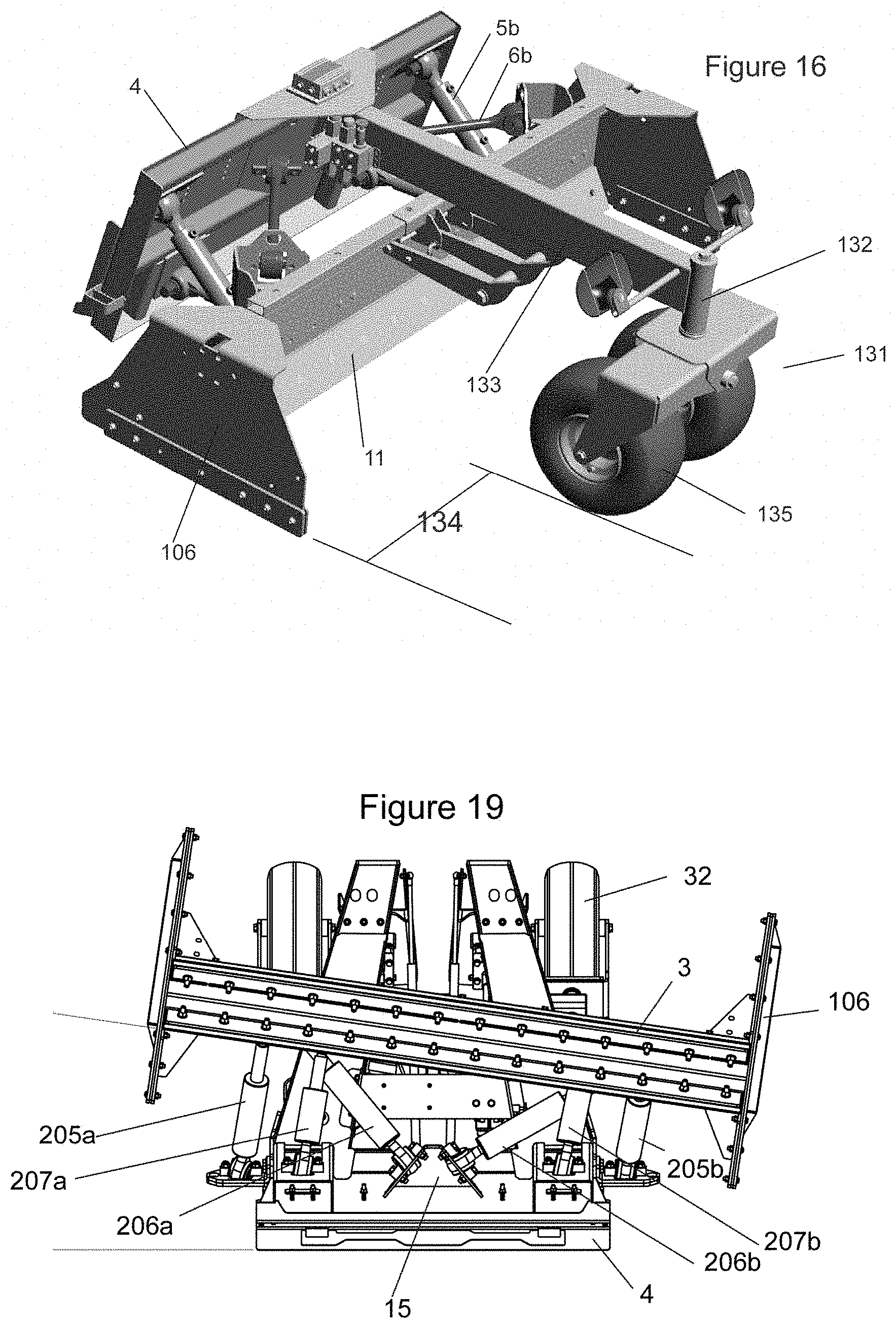
[0146] Both the translational (i.e. up/down) and rotational movements (about a forward facing axis) mentioned above may be sequentially or simultaneously effected. Specialised embodiments may also allow for some rotation of the accessory body portion, or the blade itself, about a transverse (relative to the direction of travel) axis as well.
[0147] The aforesaid movements will allow, in the case of a ground contouring assembly mounted to a vehicle performing a ground levelling operation, for the operator to maintain the bottom edge of the blade at a fixed level relative to a reference (within the limits of the capacity of the equipment to compensate for extremes in the level of the ground). With the use of a laser reference level guidance system to control the linear actuators, the accessory body portion (and hence blade) can be automatically maintained in an optimal elevation and tilt inclination to effect levelling (relative to a reference plane which need not be horizontal), ultimately within very tight tolerances.
[0148] The arrangement is also useful for attachment to excavator mounts, though a different mounting system may need to be adopted body mounting portion. Excavator mounting systems do not typically allow for any rotational (about a forward axis) adjustment of an attached blade--the ground contouring assembly of the present invention includes this feature, thereby making it possible for excavators to more effectively perform ground levelling operations.
[0149] In more advanced embodiments there is provided a stabilising wheel arrangement, typically forwardly of the blade. This wheel arrangement may be alternately between operational (contacting the ground) and non-operational positions. In a preferred arrangement the arm arrangement includes a pivoting connection allowing the end portion (with the stabilising wheel arrangement) to pivot upwardly such that the wheels clear the ground. Preferably the stabilising wheel arm of this embodiment pivots to a perpendicular position or backwardly of perpendicular, and more preferably so that the end arm portion and wheel arrangement are positioned behind the pivotable connection. This arrangement, while simple in hindsight, addresses a few significant issues and provide several realisable advantages.
[0150] For instance, one of the problems encountered during use is when an operator comes up to a boundary edge and the stabilising wheel arrangement encounters the boundary (e.g. a fence, wall, geographical feature) before the blade does. This means closest the blade can get may be around 1600-1800 mm from the boundary. By implementing the folding arm arrangement the length may typically be reduced by around 1200 mm depending on the specific design. This is much better for work in close confines. Also, as not all applications of the invention may require the use of the stabilising arm and thus the user has the option of either using the stabilising arm or having it raised, effectively converting the embodiment into a dual purpose utility device.
[0151] Additionally, for the transport of manufactured devices (e.g. on a truck or a container), space--particularly length--is critical. The ability to fold, as shown in the following illustrations, can reduce the length by around 40% which significantly decreases transport costs for multiple units when exporting or transporting cross-country.
[0152] To further improve the versatility of the present invention, a further specialised embodiment of the present invention allows the ground contouring assembly to attach directly to the existing blade of a vehicle--useful where a vehicle may not have a blade able to be quickly removed, or at all.
[0153] Preferred implementations of these embodiments have at least one first hook like feature for engaging the top edge of an existing vehicle blade, and at least one second hook like feature for engaging the bottom edge of said existing vehicle blade. At least one of said first and second hook like features will include tightening means (typically on a link to the ground contouring assembly) which allows the ground contouring assembly to be drawn tight against said existing vehicle blade--and subsequently relaxed for release from the existing vehicle blade. This represent a quick and effective system for securing ground contouring assembly to an existing blade.
[0154] Hence, in summary, ideally the geometry of the linkages between the body portions allow for the rotational angle of the blade portion (and hence blade) to be altered relative to the attachment portion, as well as its elevation relative thereto. In this case we are using the attachment portion as our reference point. In reality the blade edge itself will be come the fixed point, relative to a reference point of true ground level and true horizontal. Hence the blade will be maintained in the same position (as far as is possible) despite changes in the pitch or roll of the vehicle to which the ground contouring assembly is attached.
[0155] To allow for the relatively independent control of each end of the blade portion, the primary stabilising linkages will have pivoting ends--preferably a ball joint--to accommodate the geometry changes as the actuators are extended or contracted. In this case the geometry is chosen also to provide lateral stability of the two body portions, as well as substantially maintaining their distance of separation (major differences here as the blade changes position can affect the outcome for a device mounted on a moving vehicle).
[0156] For applications where ground preparation is necessary or desirable, preferred embodiments also include an accessory mounting system to allow for the attachment of accessories such as scarifiers, or Harley rakes and the like. For simplicity of description, reference will be made primarily to fixed tine (non-powered) scarifier rakes and Harley rakes as representative examples for illustrating the principles of this aspect of the invention.
[0157] While a simple mounting bar could be added, operators often work between areas with different characteristics. Continuously fitting and removing accessories for when needed or not can make a significant dent in productivity. Hence a more versatile solution enabling a mounted accessory to be deployed when required can potentially make a significant productivity advantage.
[0158] In simpler embodiments of a ground contouring assembly there are provided side guards either side of the blade and mouldboard elements. These are ideally strengthened or significantly strong to allow the mounting of an accessory (such as a Harley rake, scarifier, etc.) to be mounted between them. In these simpler embodiments, the complete accessory can be mounted on pivotable mounts on the side guards. This arrangement should allow the mounted accessory to rotate between at least an accessory retracted position, and at least one accessory engaged position (there may be a degree of variation here to allow multiple or continuous positions). While manual means may be used, provision may be made on the mounted accessory for the connection of a linear actuator, connected at its other end to a point on the ground contouring assembly, to allow rotation of the mounted accessory between the aforesaid accessory retracted and accessory engaged configurations.
[0159] In more preferred embodiments, there is provided a transverse accessory mount spanning said side guards, or similarly acting supports. This is rotatably mounted to allow rotation about a transverse axis, typically substantially parallel to the blade or mouldboard. It is typically mounted forwardly of the mouldboard, and the blade, and elevated above the latter. The distance forward of the blade and mouldboard can vary according to the accessory and its operation. While the mounting of a non-powered scarifier could be close to the mouldboard and/or blade, a powered drum such as a Harley rake may benefit from being further forward to allow space between it and the blade for accumulated material. Hence a more universal design of an accessory mount is likely to be further forward, but it is envisaged that the provision of multiple accessory mounts is within the scope of the present invention and it is recognised that only the more forward mounting assembly may be effectively operational (able to rotated between engaged and retracted positions) if implements were fitted to both simultaneously (e.g. a non-powered scarifier at the rear and a Harley rake at the front, for instance).
[0160] Referring to the embodiment of a single rotatable accessory mounting portion, there will typically be provided mount rotation means to allow the transverse accessory mount (and any attached accessory) to be managed between the aforesaid accessory engaged and retracted positions. In its simplest form this may be a linear actuator, probably hydraulic in operation, which the operator can control by some means.
[0161] A potential advantage of the use of the rotating transverse mount assembly is that a strong and reliable connection can be made between the transverse accessory mount and side support elements (e.g. side guards). Also the mount rotation means can remain connected rather than having to be affixed every time an accessory is changed, fitted, or removed. Also it is possible for the ground contouring assembly to be raised, maneuvered so the transverse accessory mount is above the accessory, and lowered down (guide plates may be provided) so any connecting pins or attachments can be secured. This can speed the process of fitting, removing, and changing accessories as required.
[0162] Where a powered drum, such as a Harley rake, is the accessory, advantage may be obtained by including inboard motors within the body of the drum--as opposed to external chain drives, etc. Such inboard motors may be hydraulic in operation, and fitted at either end of the drum/body portion. This would allow an accessory to extend the full width of the mouldboard and blade, and side guards where present. The potentially realisable advantage in practice is that it enables an operator to work the ground very close to a boundary while working in either direction--where single end chain drive systems are used, working close to a boundary is only possible when the chain arrangement is farthest from the boundary (hence the operator may need to travel to the end, turn around, and come back in the favourable direction).
[0163] Where a fixed (non-powered) scarifier is fitted, the scarifier may comprise one or more modules with downward tines which are either connected directly to the transverse accessory mount, or to a mount which itself attached to the transverse accessory mount.
[0164] As scarifiers may undergo significant pressure in the forward direction, they may be provided with back support. This could be a fixed bar or element extending from or between the side guards, or like. Alternatively part of the scarifier assembly may bear against the mouldboard and/or blade (though preferably the former) so that the accessory body portion bears some of the force acting on the tines/scarifier.
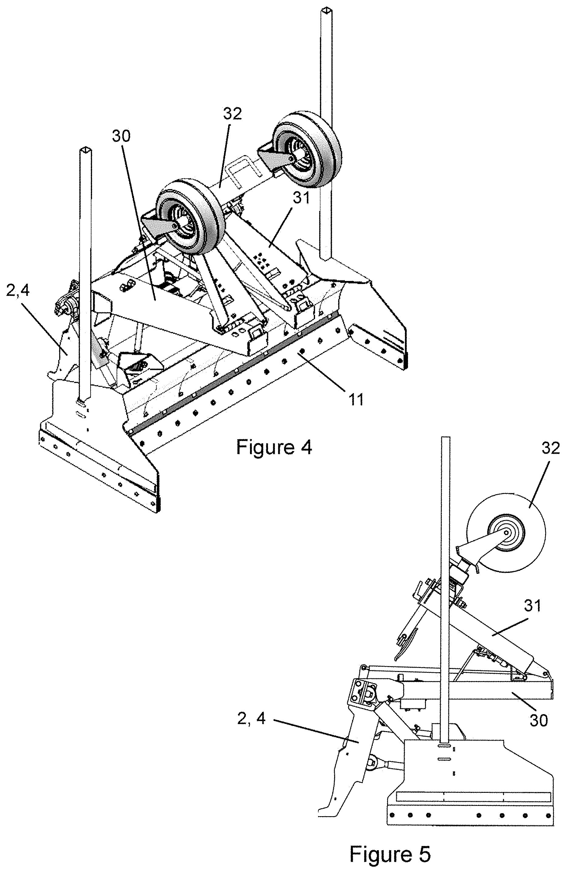
[0165] In preferred embodiments there is included an option to allow the mount rotation means to relax--e.g. for a linear actuator to travel without resistance. Where a fixed scarifier, such as above, is used, it is typically doing its primary work when the ground contouring assembly is moving forward. If it is supported at its rear by the mouldboard and/or blade (or other element(s)) then the mount rotation means is temporarily redundant. In preferred operation of a fixed scarifier, it can be more useful for the tines to drag over the ground (instead of penetrating) when the ground contouring assembly is being reversed. Hence the provision of a relaxed mount rotation means would allow this to happen, though it could be operated when the scarifier needed to be moved to an accessory retracted position.
[0166] It is envisaged that this provision to relax the mount rotation means may be useful for various accessories which may be fitted to a transverse accessory mount.
[0167] The nature and operation of the embodiment described above will be better described with reference to the drawings.
DESCRIPTION OF DRAWINGS
[0168] FIG. 1 is a partial plan view of one preferred embodiment of the present invention,
[0169] FIG. 2 is a perspective view of the embodiment of FIG. 1 in an alternative configuration,
[0170] FIGS. 3a-3c are front views of the embodiment of FIG. 1, where FIG. 3a illustrates the blade in a lowered position (about a forward axis), FIG. 3b illustrates the blade in a raised position (about a forward axis), and FIG. 3c illustrates the blade in an inclined position (about a forward axis),
[0171] FIG. 4 is a perspective view of an alternative embodiment of the present invention in a folded configuration,
[0172] FIG. 5 is a side diagrammatic view of the embodiment of FIG. 3,
[0173] FIG. 6 is a side diagrammatic view of FIG. 4 in an extended configuration,
[0174] FIG. 7 is a perspective view of the embodiment in FIG. 6,
[0175] FIG. 8 is a side diagrammatic view of a further embodiment of the present invention attached to the existing blade of a vehicle, and
[0176] FIG. 9 is a perspective view of the embodiment of FIG. 8,
[0177] FIG. 10 is a partial perspective view of an embodiment of a ground contouring assembly showing an embodiment of a rotatable accessory mounting portion, without fitted accessory, in an accessory retracted position,
[0178] FIG. 11 is a part side view of the embodiment of FIG. 10 with an embodiment of an accessory comprising a power drum fitted and in a position between retracted and engaged configurations,
[0179] FIG. 12 is a side perspective view of an embodiment of a ground contouring assembly with the embodiment of a power drum of FIG. 11 in an accessory engaged position,
[0180] FIG. 13 is a cross-sectional transverse plane diagrammatic view of a power drum as used in the embodiments of FIGS. 11 and 12,
[0181] FIG. 14 is a side perspective view of an embodiment of a ground contouring assembly illustrating laser guidance receivers and mounts,
[0182] FIG. 15 is a perspective view of an embodiment of a scarifier accessory module,
[0183] FIG. 16 is a top-side perspective view of an alternative embodiment of a ground contouring assembly showing a fixed transverse mount arrangement with an embodiment of a scarifier module, and an alternative embodiment of a forward support carriage arrangement,
[0184] FIG. 17 is a top side perspective view of a further embodiment of a ground contouring assembly ground contouring assembly capable of yaw and pitch adjustment of the accessory body portion.
[0185] FIG. 18 is a side diagrammatic view of the embodiment of FIG. 17 in which the accessory body portion is pitched forwardly,
[0186] FIG. 19 is a plan diagrammatic view of the embodiment of FIGS. 17 and 18 with wheels in folded position and in which the yaw of the accessory body portion about a vertical z-axis has been adjusted,
[0187] FIG. 20 is a front diagrammatic view showing the general principles of a preferred embodiment of a low pivot carriage/walking beam,
[0188] FIG. 21 is the schematic diagram of the embodiment of FIG. 19 with the carriage portion pivoted out of the ground plane,
[0189] FIG. 22 is a partial side view of the embodiment of a preferred embodiment of the present invention,
[0190] FIG. 23 is a partial left side, bottom-rear perspective view of the embodiment of FIG. 2,
[0191] FIG. 24 is a partial plan view of the embodiment of FIG. 2, and
[0192] FIG. 25 is a partial left side, top-front perspective view of the embodiment of FIG. 2.
DESCRIPTION OF PREFERRED EMBODIMENTS
[0193] With reference to the drawings (particularly FIGS. 1 and 2), and by way of example only, there is provided a ground contouring assembly (generally indicated by arrow 1) comprising a body attachment portion (generally indicated by arrow 2) and an accessory body portion (generally indicated by arrow 3);
the two body portions (2, 3) being connected by body connecting linkages (5-7) which allow a substantially translational movement of the accessory body portion (3), substantially parallel and relative to the accessory body portion (2)--see for instance FIGS. 3a and 3b; the body connecting linkages (5-7) also allowing a rotational movement of the accessory body portion (3), relative to the body attachment portion (2), about a rotational axis substantially in the direction of forward travel (9) of the assembly (1)--see for instance FIG. 3c; said body connecting linkages including linear actuators (5a, b), there being at least one linear actuator (5) being present either side of the middle (10) of the ground contouring assembly (1) when viewed in plan; said body connecting linkages (5-7) also including at least one pivot-ended stabilising linkage (6-7) either side of the middle (10) of the ground contouring assembly (1) when viewed in plan; and wherein the body connecting linkages (5-7) assist in maintaining relative movement of the body portions to as described above.
[0194] The body attachment portion (2) includes a quick-hitch arrangement (4) such as commonly used on skid-steer tractors.
[0195] With reference to FIG. 3 in the illustrated embodiment (1) there are two hydraulically controlled upper linear actuators (5a, b) which can be independently controlled to alter the relationship of each end of the blade portion (3) relative to the body attachment portion (2). This is best illustrated in FIG. 2, where right hand actuator (5b) is contracted relative to left hand actuator (5a) to adopt a configuration such as shown in FIG. 3c. While lower linkages (7) may comprise connecting arms, these may also comprise hydraulically controlled lower linear actuators which work in cooperation with actuators (5) to allow the accessory body portion to adopt the configurations shown in FIG. 3, and combinations thereof. This arrangement can also allow for alteration of the inclination of the blade (11) about a transverse axis, under the control of the operator.
[0196] The stabilising linkages, pivot-ended linkages (6a, b) (7a, b) have ball joint ends where they attach to at least one of the body portions (2, 3) which is necessary to allow for the permitted relative movements of the body portions (2, 3). In the present invention a spherical bush is used in the joints--this joint (14) can be clearly seen in the stabilising arms (6) where they (in this embodiment) attach to a central mounting point (15) on the body mounting portion (2).
[0197] The geometry of the remaining connecting linkages (stabilising arms (6-7)) assist in maintaining the relationship between the two body portions (2, 3) as movement occurs (such as shown in FIG. 3). In this arrangement the distance of separation between the body portions (2, 3) remains substantially the same, as does their relative forward/rearward inclinations (i.e. inclination being rotation about a transverse axis) relative to each other (though some flexibility is allowed here in the design of the geometry in various embodiments).
[0198] The primary permitted relative movements between the body portions (2, 3) are, when viewed from the front and wherein the body attachment portion (2) is considered fixed in position, relative upward and downward movement of the accessory body portion (3) relative to the body attachment portion (2), as well as allowing relative upward and downward movement of each end of the accessory body portion (3) relative to the body attachment portion (2)--allowing also for inclination of the blade portion (3) (relative to the body attachment portion (2)), such as shown in FIG. 2.
[0199] Accordingly there is provided a precise alteration of the elevation and rotational inclination of the blade relative to the quick hitch (4) (which follows the roll inclination of the vehicle in response to ground contours) without the need for heavy and expensive quick hitch rotational attachments. The arrangement of the illustrated embodiment theoretically provides for faster (quick response movements are important for a moving vehicle) changes to the elevation and rotational inclination of the blade, as well as being much more precise.
[0200] The actuators can also be coupled to a laser levelling control system (sensors or emitters can be mounted on arms (not shown) which fix at positions (12) on the blade portion (3)) so that the blade (11) is maintained at true ground elevation and the horizontal, regardless of any pitching and rolling movements of the vehicle to which it (1) is attached. As mentioned above, the quicker responsiveness of the present embodiment also allows the vehicle to travel faster.
[0201] Preliminary trials by the inventor, have indicated that the present invention when used with a laser levelling system can level ground to a much higher degree of precision (.+-.3 mm compared to .+-.10 mm) approximately 12 times faster than when using a similar arrangement with a prior art device. This represents a very significant advance in the art in terms of productivity and precision. Accordingly this also opens the present invention up to other applications where a tool on a moving vehicle needs to be maintained at a precise inclination and elevation.
[0202] In FIGS. 4 and 5 we see a folding embodiment of the present invention, where a provided stabilising arm assembly (30) has a folding end portion (31) on which a ground contacting stabilising wheel arrangement (32) is mounted.
[0203] In FIG. 5 the reduced front to rear length of the apparatus is evident, as are the potential transport benefits. Similarly, the closer proximity of the blade (11) to the front of the apparatus, for close work, can be gauged.
[0204] In FIGS. 6 and 7 we see a further embodiment suitable for attachment to an excavator. Rather than a quick hitch (4) we have an arm arrangement (50) to which is pivotably attached (53) a T-pin (51) comprising a quick hitch adaptor (which may be of different quick connect configurations) to which the quick hitch adaptor (54) of an excavator's (not shown) dipper arm (52) may be attached. This arrangement makes the ground contouring assembly available for use with excavators, a new and novel arrangement which significantly improves the versatility of both excavators and levelling devices.
[0205] In FIGS. 8 and 9 we see an alternative mounting system to the ubiquitous quick hitch (4), the body mounting portion (70) attaching to the existing blade (71) of a vehicle (not shown for simplicity).
[0206] Here at least one upper hook portion (72) affixed to the body mounting portion (70) hooks over the top of the existing blade (71). A contacting bar (78) may be provided on the body mounting portion (70) to help accommodate the different curves of blades and reduce possible damage to the blade (71).
[0207] A lower hook portion (73) connected by a flexible linkage (74) to an adjustable linking element (75), in turn connected to an element (79) associated with the body mounting portion (70), helps secure the ground contouring assembly (1) to the existing blade (71) as the adjustable element(s) (75) are tightened. The adjustable element (75) may simply be a turnbuckle in a preferred element, and may be provided with an arm (76) to help tighten the turnbuckle, and provide additional stabilisation when the distal end of the arm (76) is connected to a point (77) on the accessory body portion (3) after tightening.
[0208] In FIG. 10 we see an embodiment of a modified ground modifying assembly including a rotatable accessory mounting portion (101) comprising a transverse accessory mount (102), in simplest form comprising rectangular hollow section bar, connected at each end to side supporting elements (in this case comprising side guards) (106) by rotatable mounts (105) allowing at least partial rotation of the mount (102) about a transverse axis substantially in parallel with the general plane of the blade (11) or mouldboard (107) of the accessory body portion.
[0209] Linkage tabs (104a,b) allow for control of the rotation of the mount (102) by allowing the connection of mount rotation means comprising linear actuators (103a,b). In preferred embodiments these are hydraulic and capable of progressive and continuous control by the operator, and/or could be linked into an automated control system. In this figure the mount (102) is shown in an accessory retracted position.
[0210] In FIGS. 11 and 12 we see the inclusion of a power drum assembly (generally indicated by arrow 110) such as a Harley rake (114) to the rear of structure support wheel (32). Features such as teeth or studs (115) may be provided on the Harley rake drum (114). While the invention allows for such an assembly (110) to be attached directly to side supports (106) by a rotatable mount (e.g. 105) at each end, the preferred arrangements utilise the rotatable transverse accessory mount (101) of the embodiment of FIG. 10 for easier fitment and removal of accessories (e.g. 110).
[0211] FIG. 12 provides a perspective view of the embodiment of FIG. 10 with the power drum accessory (110) of FIG. 11 (and such as detailed in FIG. 13) fitted and in the engaged position.
[0212] FIG. 13 illustrates a preferred power drum accessory (110) arrangement such as would be used in preferred embodiments as described in relation to FIGS. 11 and 13. As mentioned in the main body of the specification it is desirable for operators to be able to work close to boundaries and obstructions--e.g. foundation walls, kerbing, marker poles, etc. In practice this can usually be achieved in embodiments of the invention by minimising protrusions outside of the width of the blade (11), or as more readily seen in the pictures, outside of the side guards 106.
[0213] While the power drum could utilise a compact external hydraulic motor at each end the option for preferred embodiments is predominantly inboard hydraulic motors (112a,b) positioned largely within the drum (114) itself. In this situation only the protective cap and mount (111a,b) need extend outside of the planes defined by the side guards (106) while allowing the drum (114) to extend the full width within the extended vertical planes defined by the side guards (106).
[0214] The protrusions (115) from the drum (114) are defined by choice, and may be replaceable elements or formed into drum (114) itself. The user is open to choice here. Various types of teeth, blades, features may be provided along with different combinations thereof--for instance the user choice for breaking asphalt and road-seal may be different from dethatching and preparing areas covered with vegetation.
[0215] Less destructive drum choices are also envisaged--for instance the power drum may comprise a brush for finishing and screening areas, finishing landscaped areas or lightly covering sown seed, or even removing excess materials and debris on finished areas (e.g. gravel chips on finish tar sealed roading and sidewalks etc). It is intended that there will be user choice in the selection of the properties of the power drum in a power drum assembly (110).
[0216] FIG. 14 illustrates a different perspective view of the embodiment of FIG. 12, and also shows the laser receiver unit (116a,b) guide poles (117a,b) which can employed with various embodiments of a ground contouring assembly (1) to enable it to be used a laser guidance and levelling system, or full 3D guidance system, such as becoming more common in the industry. There are various manufacturers of such systems (including, for instance, Leica.RTM.) which can provide accessory guidance and control systems able to work with position transmitters and solutions for use on various sites (and types of site). A potentially realisable advantage of various embodiments of the present invention is that when such laser assisted systems are used, any mounted accessories on the accessory body portion also operate under the same laser assisted control as the blade and benefit from the advantages thereof. Hence a ground contouring assembly of the present invention to which various accessories can be fitted provides a useful advance in the industry--the multiple linkage arrangement connecting the accessory body portion to the body attachment portion allows for angling of the accessory under operator control and/or in response to laser assisted control systems. No prior art accessories such Harley rakes/power drums, scarifiers, etc are able to be angled in response to changing ground contours and this represents a significant disadvantage (multiple passes with different accessories) in terms of time and accuracy for land and site preparation and contouring.
[0217] The following specifications in relation to the embodiments of FIG. 10 through 15 are not intended to be limiting but representative only of a currently most preferred embodiment, and to provide additional information to the skilled reader in understanding a best preferred embodiment of the invention. However, it should be appreciated that many of these parameters are open to user choice and to suit a particular job. [0218] Typical Drum diameter: 170 mm (without teeth) [0219] Typical Drum working width: 1.940 mm [0220] Drum type: Steel, reversible in operation without affecting levelling operation [0221] Typical Motor displacement (per side): 160-380 cc, depending on base machine size and hydraulic flow [0222] Typical Drum speed: adjustable from 0 to 240 RPM [0223] Typical Shaft diameter: 50 mm [0224] Typical Number of teeth: 96 [0225] Typical Tooth type: 16 mm tungsten with button or flat top, depending on type of work [0226] Typical Tooth height (from surface of drum): 30 mm [0227] Typical Type of drive: Direct with resilient internal toothed drive [0228] Typical Lubrication and maintenance points: zero, grease free pivots, internal, oil lubricated bearings [0229] Typical Drum support bearings: 2.times. internal, oil lubricated, maintenance free [0230] Typical Angle of retraction: 90 degrees to operating plane [0231] Typical Engagement depth: Infinitely adjustable in operation from 100 above to 70 mm below blade height [0232] Typical Stone barrier set height: 3 position in 40 mm increments [0233] Typical Clearance height with drum removed: 560 mm [0234] Typical Drum forward length from blade: 540 mm [0235] Typical Drive motor extension width past side wing gusset: 20 mm [0236] Typical Weight of drum and mount structure: 200 KG [0237] Typical Weight of pivot mounting structure: 40 KG [0238] Typical Locking mechanism: Over centre latch mechanism with positive tension in lock position [0239] Typical Tilt from level: adjustable in manual or automatic mode, 0 to +/-12 degrees [0240] Typical Control method: proportional hydraulic positioning using electronic machine control [0241] Typical Grade Control: continuous automatic from 2D laser or 3D data file, Dual GNSS or TPS capable [0242] Typical Tooth engagement depth: manual set via hydraulic cylinders [0243] Typical Maximum main fall: set by laser, typical 0-15% [0244] Typical Maximum cross fall: set by laser, typical 0-15% [0245] Typical Accuracy of cut: Typical +/-3 mm from registered grade [0246] Typical laser system provider which might be employed on embodiments--Leica.RTM.
[0247] FIG. 15 illustrates another accessory which may be fitted by an operator to an accessory mount (102). In this case a scarifier module (121) comprises a plurality of tines (123) are connected to an accessory mount portion (122) for fitting to the transverse mount (102). A pivot pin(s) (not shown) aligned with axis 124 allows for forward pivoting of the tines (123) allowing for them to drag freely when the ground contouring assembly is being reversed in operation. Alignment pins (125a, b) maintain spacing of the tines.
[0248] Apertures (126) and (127) in the mount and tine portions respectively allow an operator to temporarily lift the tines (123) and place a pin in to lock them in an up position. This can be useful for improving visibility for the operator in certain operations where the tines are not required. This can still used in conjunction with rotation of the transverse mount (102) to further lift the tines (123).
[0249] Not visible is a rear tab or bar at the rear of the mount ribs (128) which limits rearward travel of the tines (123) during forward movement of the ground contouring assembly (1), and to allow the tines (123) of the module (121) to be raised when the accessory bar is moved to an accessory retracted position.
[0250] It should also be envisaged that the scarifier modules could be positioned directly in front of the blade and mouldboards of the ground contouring assembly to allow them to be used in conjunction with another accessory on a transverse accessory mount (102), allowing an operator to readily use both in conjunction or alternate between use of the two accessories with relative ease of operation and adjustment. It should also be appreciated that a single scarifier module extending the full width of the mount (102) could be used, or multiple smaller modules used as required.
[0251] FIG. 16 illustrates a further modification to various embodiments of the present invention. In practice it is sometimes necessary for operators to work around obstructions on a site--these may be foundations for pillars or columns, and such like. As an alternative to the larger folding wheel carriage assembly (31, 32) of some embodiments of the invention, a simplified pivoting carriage with single pivot (132) can be provided and attached to a forwardly extending support (133), which may be fixed or removable. This arrangement gives a greater unobstructed distance (134) between the wheels (134) and projected general vertical plane of the side guards. This increased clearance make it easier for an operator to work close to, and around, obstructions--potentially providing a cleaner job with minimal manual follow up to finish problem areas. It should be noted that in a number of situations a forward carriage is desirable to help stop the ground contouring assembly (1) from nosing down into softer materials and maintaining a more accurate natural level for the tractor and ground contouring assembly combination.
[0252] As a variation of the aforesaid embodiments, there are occasionally situations where an operator may require additional flexibility in terms of being able to manipulate the orientation of the accessory body portion (203). Such operations may include tilting the accessory body portion forwardly or rearwardly (about a transverse axis--i.e. altering the pitch of the accessory body portion). Other operations may include rotating the angle of the accessory body portion (203) about a vertical `z` axis--i.e. a yaw type movement. And various combinations of these operations and that of previously described embodiments. It should also be appreciated that these operations also affect any accessories which may also be mounted on the accessory body portion (203).
[0253] In order to achieve these additional operations, various linkages of the previous embodiments (e.g., FIG. 8) may be substituted with linear actuators.
[0254] FIG. 17 refers a modification of embodiments such as shown in FIG. 8. For instance, to achieve pitch adjustment, linkages (7) (e.g. FIG. 8) of the previous embodiments are substituted with linear (typically hydraulic) actuators (207). These can be lengthened or shortened (ideally in tandem) to adjust pitch--we shall assume that other linkages/actuators remain at constant length while visualising this. Once a desired pitch has been achieved, their length may be maintained to retain this relative pitch (though see also more sophisticated embodiments discussed later). The beauty of this arrangement is that the actuators (207) function primarily as adjustable linkages, enabling these variant embodiments (e.g. FIG. 17) to still operate in the manner of the embodiment of FIG. 1 (for instance).
[0255] Providing linear actuators (206) to replace linkages (6) of FIG. 1 allows for the aforesaid yaw-like adjustments to be made. Here the operation is a little different and will typically involve extending one actuator (206) while retracting the other (206). The geometry is also a little different and these actions may also cause some roll-movement of the accessory body portion (203). While this might be acceptable in some embodiments, providing actuators (207) instead of fixed length linkages (e.g. 7) can help compensate and allow adjustment to reduce these other pitch and/or roll changes when adjusting yaw.
[0256] In practice it is likely that an operator may employ changes to any one or more of pitch, yaw, and roll simultaneously. It is envisaged that in most cases the operation of such advanced embodiments of the present invention will be in conjunction with laser assisted control systems--such as, for instance, provided by companies such as Leica.RTM.. In these cases a control system for the actuators (205, 206, 207 where provided) will be coupled with the laser assisted control system to ensure the accessory body portion (203) is maintained at the correct attitude/position as the leveller and vehicle travels across terrain.
[0257] It is envisaged that even with laser assisted embodiments, the operator may have direct (or indirect fly-by-wire type) control over pitch and yaw, as these are often more influenced by the type of terrain and material that the ground contouring assembly is working on. It also envisaged that these embodiments may also be used on non-laser assisted embodiments of a ground modifying assembly with direct control of the actuators (205-207 where provided) by the operator. There may also be fly-by-wire type assisted operation using computational means with a control system to enable the operator to more easily attain a particular attitude of the accessory body portion (203)--it is envisaged that such embodiments might even used modified joysticks or roller-ball type controls for the operator, rather than individual controls for each actuator and/or set thereof (i.e. 205-207 where provided). FIG. 18 illustrates the embodiment of FIG. 17 in which actuators (207) have been shortened to enable the accessory body portion to pitch forward relative to the ground (220)3. Once these actuators (207) have been set and maintained at the required length, and assuming also that actuators (206) are also maintained at constant length (assuming these are present instead of linkages (6)) then operation of actuators (205) will raise and lower the accessory body portion (203) while maintaining substantially the same pitch. In fact, operation of actuators will be substantially the same in effect as for the embodiment of FIG. 1.
[0258] With reference to FIGS. 20 and 21, and prior art ground modifying assemblies with walking beams, existing prior art walking beams (carriages supporting forward wheels) have their walking beam pivot point above the walking beam, which is significantly above the contact point of the tyres. This pivot is to allow the carriage to rotate about a longitudinal axis (with respect to the leveller/ground modifying assembly) to allow wheels on the carriage to negotiate bumps and contours in uneven ground being worked.
[0259] As all other manufacturers position their pivot point in this position, the applicant had also assumed this to be the correct point, as the walking beam always hangs level when raised off the ground. However, this has turned out not to be the case.
[0260] When a ground modifying assembly is turned (particularly in reverse) with the wheels raised at all, the natural motion of the pendulum action of the suspended weight of the walking beam and wheels assembly causes the leading wheel in the turn to contact the ground. This is due to the centre of gravity being below the pivot point. If the material is soft (which is the case at the end of a push (forward operation of a ground modifying assembly) as it has not had a blade or ground modifying accessory pass over it to compact/level/contour it, the contacting wheel makes an impression in the ground. In addition, the wheel may be pivoting around to change direction, further compounding the impression in the soft material. This immediately causes the walking beam to increase in angle, further amplifying the problem. The walking beam will then act as an anchor and drive the wheel into the soft ground, as the high pivot point creates a high angle of attack to try and force the whole ground modifying assembly around this point. Apart from marking levelled and worked ground, it puts severe strain on the assembly's structure. This all happens in a split second, so is difficult for the operator to identify, as they are often looking behind to see where they going.
[0261] The force can be extreme, causing even 40 mm wheel pivots pins to be bent. All manufacturers have grappled with this issue and a solution is a longfelt want. It is not uncommon in the industry to have wheels torn completely off.
[0262] One solution of the present invention is to lower the pivot point of the walking beam as low as possible to get it below the centre of gravity of the walking beam assembly. Ideally the pivot should be below the centre of gravity of the pivoting walking beam assembly. There may be further advantage in some embodiments in placing the beam pivot point below the rotational axis of the wheels, but ground clearance (for various applications of a ground modifying assembly is a practical consideration in calculating the lowest practical pivot point in differing embodiments.
[0263] By lowering the beam pivot point, we can potentially realize several effects: [0264] A walking beam's natural pendulum tendencies in embodiments of the present invention differ from that of the prior art (which has a pivot above the centre of gravity). Thus, when a ground modifying assembly is turned with the wheels raised, or not contacting the ground, the natural action is for the leading wheel to RAISE and the trailing wheel to contact the ground. As this wheel is behind the pivot point, it forms a natural castor action, extending the length to the centre line. This reduces any force to push the wheel into the soft ground. [0265] The angle of attack is significantly reduced, as the pivot is closer to the surface of the ground. Technically, if we placed the pivot at ground level or below, there would be zero angle of attack. Of course we have to leave some room above the ground, but by lowering the pivot height compared to the prior art the angle can be reduced significantly.
[0266] The down side is the walking beam will "fall" to either side now when raised though the effects of this can be addressed with solutions such as rubber bump stops.
[0267] FIGS. 20 and 21 illustrates a low pivot version of a carriage in a schematic fashion. FIGS. 26 and 27 represent a preferred embodiment. (501) represents the forward drawbar or portion of the ground contouring assembly to which the carriage portion is affixed. For reference, an example of a high pivot walking beam such as previously used in the art, is illustrated in FIG. 14, as well as other figures such as FIG. 5.
[0268] A downward extension (502) provides a suitable mounting point for the carriage pivot portion (506). This carriage pivot (506) connects the extension (502) to the lower extending portion of the carriage body (505) to which the wheel assemblies (504) are attached. The wheel assemblies (504) of this embodiment can rotate about a substantially vertical axis by pivotable attachment (503). Ideally the wheel assemblies are a trailing type assembly in this embodiment, where (in plan) the central wheel pivot is offset from vertical pivot (503).
[0269] The applicant has found that by positioning the carriage pivot (506) below the central pivot of the wheels (504) the pendulum and swinging effects of high mounted pivots (such as in earlier figures) is reduced, minimised, or even eliminated. Hence this arrangement may be applied to suitable embodiments of FIGS. 1 through 18.
[0270] FIGS. 26 and 27 illustrate a working embodiment of a ground modifying assembly (530) with and underslung pivot (506). In FIG. 27 a simple embodiment which might be used on an excavator arm is shown. Here the ground working accessory (520) is a blade, and this faces away from the wheel portion--typically an excavator will use its boom/arm to draw the ground modifying assembly (530) towards it. However it should be appreciated that this ground working accessory (520, 521) may, in other embodiments, be substituted by other body and accessory portions as in other figures of this specification--or in other words, the underslung pivot (506) carriage arrangement may be substituted for the wheeled carriage portions appearing in embodiments illustrated in other figures herein.
[0271] FIG. 26 illustrates how, when the apparatus is lifted from the ground (or travelling over uneven ground) the front carriage portion (503, 504, 505) will tilt to one side of the other (if dangling) or tilt to follow ground contours. Rubber stops (518) may be provided to lessen shock as it meets the maximum rotation limit.
[0272] FIGS. 22 through 24 comprise a different embodiment of a leveller which uses a simpler parallel type linkage arrangement. This arrangement is potentially useful in some embodiments of levellers (ground modifying assemblies), and particularly for excavator mounted levellers. Depending on the size of an excavator (or other vehicle with a movable support arm) there may be a weight restriction on attached accessories which also has a bearing on the maximum reach, maximum angle of inclination of a ground plane on which the excavator/vehicle is working, etc.
[0273] In FIGS. 22 through 25 is shown an alternative embodiment which uses a simpler linkage system which can yield a lighter leveller type assembly--potentially a significant advantage for excavators. There are also some other potentially realisable benefits which can lead to increased usage and field of operation of leveller assemblies. Such potential benefits may include: lower manufacturing costs, lighter weight, simpler control of moving parts.
[0274] We will refer back to FIG. 1, which represents the geometry of the applicant's prior art levelling assembly for comparison. Here the fixed diagonal linkages (6a, b) between the front accessory body portion (3) and the rear body portion (2) effectively prevents sideways lateral movement--which was considered a desirable attribute for the intended uses of this device. However, now the art and industry needs apparatus with lateral adjustment.
[0275] In another embodiment of the present invention and with reference to the drawings, and by way of example only, there is provided a levelling assembly (see FIG. 22) comprising a front accessory body portion (603), and a rear body portion (602),
the two body portions (602, 603) connected to each other by at least four body connecting linkages (L605, L606, R605, R606), said body connecting linkages, in plan view, being distributed either side ((L605, L606) and (R605, R606)) of a vertical longitudinal centre-plane (607) bisecting said two body portions (1602, 603), said body connecting linkages ((L605, L606) and (R605, R606)) including pivotable linkage connections to said body portions (602, 603) to allow, when viewed from the side, the relative elevation to the two body portions (602, 603) to alter.
[0276] The front accessory body portion (603) includes a blade (608) attached to a mouldboard portion (609) and has collectively been referred to as the "blade" previously in this specification. Side guards (L610 and R610) may be provided or both sides, one side only, omitted, or removably attached as required.
[0277] The rear body portion (602) provides a body structure including a mounting point (612) for one end of an actuator (614) comprising the lateral shift control linkage. A pivotable bush or ball joint type connection may be provided here (612). The other end (615) of the actuator (614) is attached to the front accessory body portion (603) though due to the partially cut away view the mounting attachment point is not fully visible.
[0278] The rear body portion (602) may also include an attached quick hitch mount as required, and as is visible as item (4) in FIG. 1.
[0279] In the side view of FIG. 24 from the left side, we can see the upper (L605) and lower (L606) connecting linkages connected (L705 and L706) to the structure of the body portion (602). FIG. 3 better shows the alternate end pivotable connections (L805 and L806) for the respective linkages (L605 and L606) to the rear structure of the front body portion (603). Referring back to FIG. 2 we can see the preferred substantially parallelogram arrangement of this embodiment between the connecting linkages (L605, L606) and the body portions (602, 603). The arrangement and geometry of the right hand side is typically a mirror replication through the centre plane (607).
[0280] FIG. 25 shows the left (L618) and right (R618) elevation controlling linkages, comprising linear hydraulic actuators. FIG. 2 illustrates the diagonal mounting arrangement (from side view) of left (equivalent to right) elevation controlling linkage (L618), and its connection (L818) near the top of the rear body portion (602) though the connection (L818) to the front body portion (603) is obscured in this figure.
[0281] These elevation controlling linkages (L618, R618) may be placed inwardly (closer to the centre plane (607)) or outwardly of the left and right sets of connection linkages ((L605, L606) and (R605, R606)) as convenient or desired.
[0282] The levelling apparatus may also include an excavator boom arm quick mount (626) if this is a required vehicle mounting option.
[0283] Laser sensor poles may be affixed at mounting points (L628, R628) on the side guards (L610, R610) if required, and sensors (not shown) attached.
[0284] A forward wheel assembly, possibly upwardly folding or retractable may be provided on various embodiments though this may not be required on all embodiments,
[0285] A kerb following wheel assembly may be provided on one or both sides of the front accessory body portion (602) to assist an operator in precision following of an existing structure or feature.
[0286] With general reference to the embodiments of FIGS. 22 through 25, other embodiments are possible. For instance in the applicant's previous levelling apparatus (U.S. Pat. No. 10,323,382) the linkage geometry precluded relative lateral shifting of the body portions in order to achieve rotation about a longitudinal axis. Accordingly this document teaches away from the present invention, as well as there being considerable changes in geometry.
[0287] In preferred embodiments of the general parallel linkage arrangement of FIGS. 22 through 25 there are ideally four connecting linkages. These are typically divided into two sets of two, which are conveniently referred to as left and right linkage sets, and distributed (ideally substantially equidistantly) outwardly of a vertical longitudinal centre plane (within which the levelling assembly's longitudinal axis in use also lies). Typically no connecting point for a connecting linkage is near the centre plane in preferred embodiments.
[0288] When preferred embodiments are view from the side, the two connecting linkages of each set are displaced vertically with respect to each other--i.e. one appears positioned above the other, and in preferred (but not necessarily all) embodiments is vertically displaced one above the other. As (also in preferred embodiments) the general planes of the two body portions are roughly parallel to each other, from the side the arrangement of the two connecting linkages (of a set) with the two body portions form a quadrilateral. This may ideally be a parallelogram but in practice may deviate from this precise geometry, and various contributing elements to this parallelogram may (typically) each fall up to (and including) 20 degrees of this ideal parallelogram.
[0289] In order for there to be relative movement between the body portions we need to have a pivotable connection between same and the connecting linkages. While this may be a connection pivotable about a single axis (suitable for simple more limited embodiments of the present invention with a restricted range of movement), the desired range of movement in preferred embodiments prefers a more multi-axial range of movement such as provided by a ball joint. In practice, a single axis mounted connection with a flexible bush accommodating movement in other directions (such as by bush compression) is often suitable--truck suspension arm/component connections with compressible bushes are one example. At the end of the day, a pivotable connection which allows for the desired relative movements is used.
[0290] The elevation controlling linkages are typically also connected to the body portions with pivotable connections equivalent to the connecting linkages. The elevation controlling linkages are typically actuators, and hydraulically controlled in preferred embodiments. These are typically operated in tandem, though users may operate them differently and in the geometry of the preferred embodiment limited rotation of the two body portions relative to each other is possible by altering the length of the actuators by different amounts. This is useful where the leveller is used to create an incline (e.g. roading etc.) during its operation. Hence preferred embodiments of the present invention can provide lateral and elevational translational movement, as well as longitudinal axis rotational movement, relative between the front and rear body portions.
[0291] Typically an elevation controlling linkage is mounted substantially diagonally in side view, often being connected (in side view) at or near the top of one body portion and at or near the bottom of the other. Variations may exist in practice, though the requirement is to be able to change the relative elevation of one body portion to the other by altering the length of said elevation controlling linkage.
[0292] It should be recognised that it is also possible to substitute linear actuators for one or more of the connecting linkages, so as to provide a greater range of relative conformations between the front and rear body portions, though this does add to the complexity and cost of the resulting apparatus. However, for specialised applications, this may become a viable option.
[0293] Lateral translation control may be provided by a lateral shift control linkage. In simple terms this may be a substantially transverse linear actuator connected at one end to the front accessory body portion, and at the other end to (or an element attached or part of) the rear body portion. Typically, in plan view, one end of the lateral shift control actuator linkage will be connected to one of the body portions at or towards its left side, and the alternate end to the other of the body portion at or towards its left side. While this actuator may be normal to the longitudinal centre plane, in practice it may be at an angle to the transverse so as to take advantage of suitable mounting points on the body portion and/or to avoid obstruction with other parts, portions, or components of the levelling assembly.
[0294] Laser sensor guide poles may be provided on various embodiments, allowing for the mounting of laser guidance sensors and their integration in to optionally provided laser guidance control systems available in the market.
[0295] Various mounting systems may be provided. A typical almost industry standard quick hitch mount (as commonly used on skid-steer loaders) may be provided on various embodiments. Other options include mounting attachments for boom arms such as commonly present on excavator arms. Various options may be implemented according to user need.
[0296] Aspects of the present invention have been described by way of example only and it should be appreciated that modifications and additions may be made thereto without departing from the spirit or scope of the present invention as described herein.
[0297] It should also be understood that the term "comprise" where used herein is not to be considered to be used in a limiting sense. Accordingly, `comprise` does not represent nor define an exclusive set of items, but includes the possibility of other components and items being added to the list.
[0298] This specification is also based on the understanding of the inventor regarding the prior art. The prior art description should not be regarded as being authoritative disclosure on the true state of the prior art but rather as referencing considerations brought to the mind and attention of the inventor when developing this invention.
* * * * *
D00000
D00001
D00002
D00003
D00004
D00005
D00006
D00007
D00008
D00009
D00010
D00011
D00012

D00013
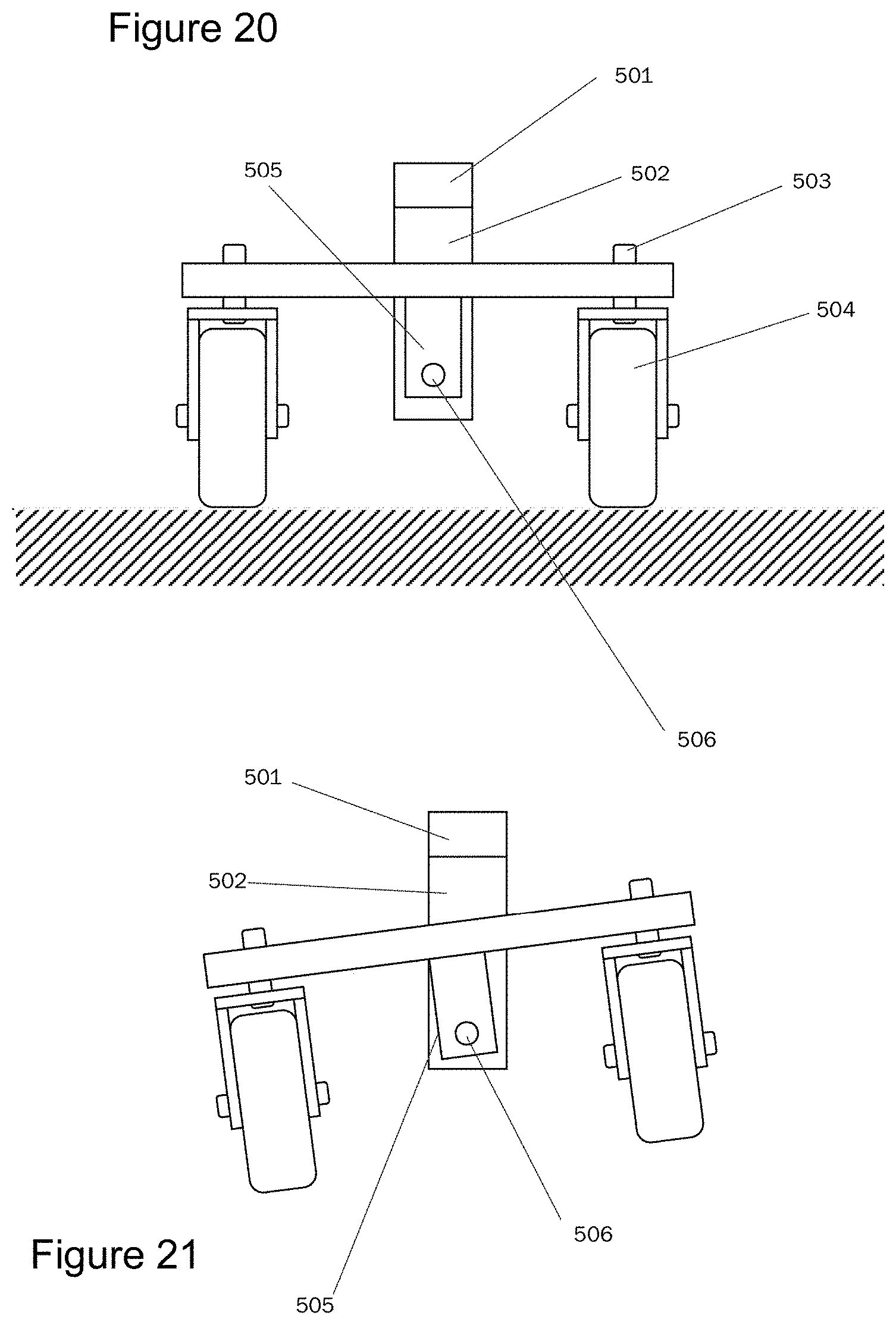
D00014

D00015
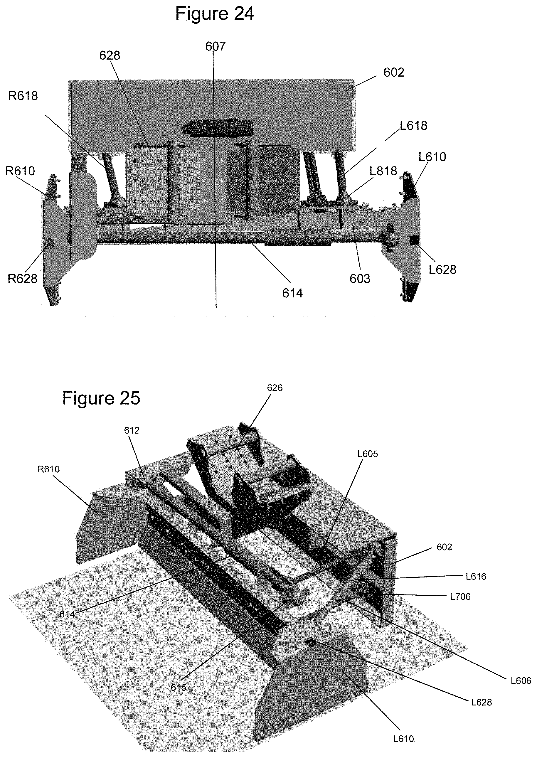
D00016

XML
uspto.report is an independent third-party trademark research tool that is not affiliated, endorsed, or sponsored by the United States Patent and Trademark Office (USPTO) or any other governmental organization. The information provided by uspto.report is based on publicly available data at the time of writing and is intended for informational purposes only.
While we strive to provide accurate and up-to-date information, we do not guarantee the accuracy, completeness, reliability, or suitability of the information displayed on this site. The use of this site is at your own risk. Any reliance you place on such information is therefore strictly at your own risk.
All official trademark data, including owner information, should be verified by visiting the official USPTO website at www.uspto.gov. This site is not intended to replace professional legal advice and should not be used as a substitute for consulting with a legal professional who is knowledgeable about trademark law.