Automatic canning device for canned food
Zhu; Xiaofeng
U.S. patent application number 16/702545 was filed with the patent office on 2020-04-02 for automatic canning device for canned food. The applicant listed for this patent is Xiaofeng Zhu. Invention is credited to Xiaofeng Zhu.
| Application Number | 20200102107 16/702545 |
| Document ID | / |
| Family ID | 68516878 |
| Filed Date | 2020-04-02 |


| United States Patent Application | 20200102107 |
| Kind Code | A1 |
| Zhu; Xiaofeng | April 2, 2020 |
Automatic canning device for canned food
Abstract
The invention discloses an automatic canning device for canned food, which includes a machine body. The weighing device includes a rotation shaft that is rotatably installed on the front and rear side walls of the transportation cavity. A large gear is fixed on the rotation shaft. The rear side wall of the transport chamber is provided with a long plate chute. The bottom side of the long plate chute is provided with a hydraulic pipeline. The power motor is turned on, thereby driving the large gear, pinion, and symmetrical pulley to rotate. The device can add jam to the glass jar through a mechanical structure. Compared to manually adding jam, the content of jam added by the device can be kept consistent, so that the product Standardization can be guaranteed, and the device can automatically seal glass bottles and then tighten them.
| Inventors: | Zhu; Xiaofeng; (Xiamen city, CN) | ||||||||||
| Applicant: |
|
||||||||||
|---|---|---|---|---|---|---|---|---|---|---|---|
| Family ID: | 68516878 | ||||||||||
| Appl. No.: | 16/702545 | ||||||||||
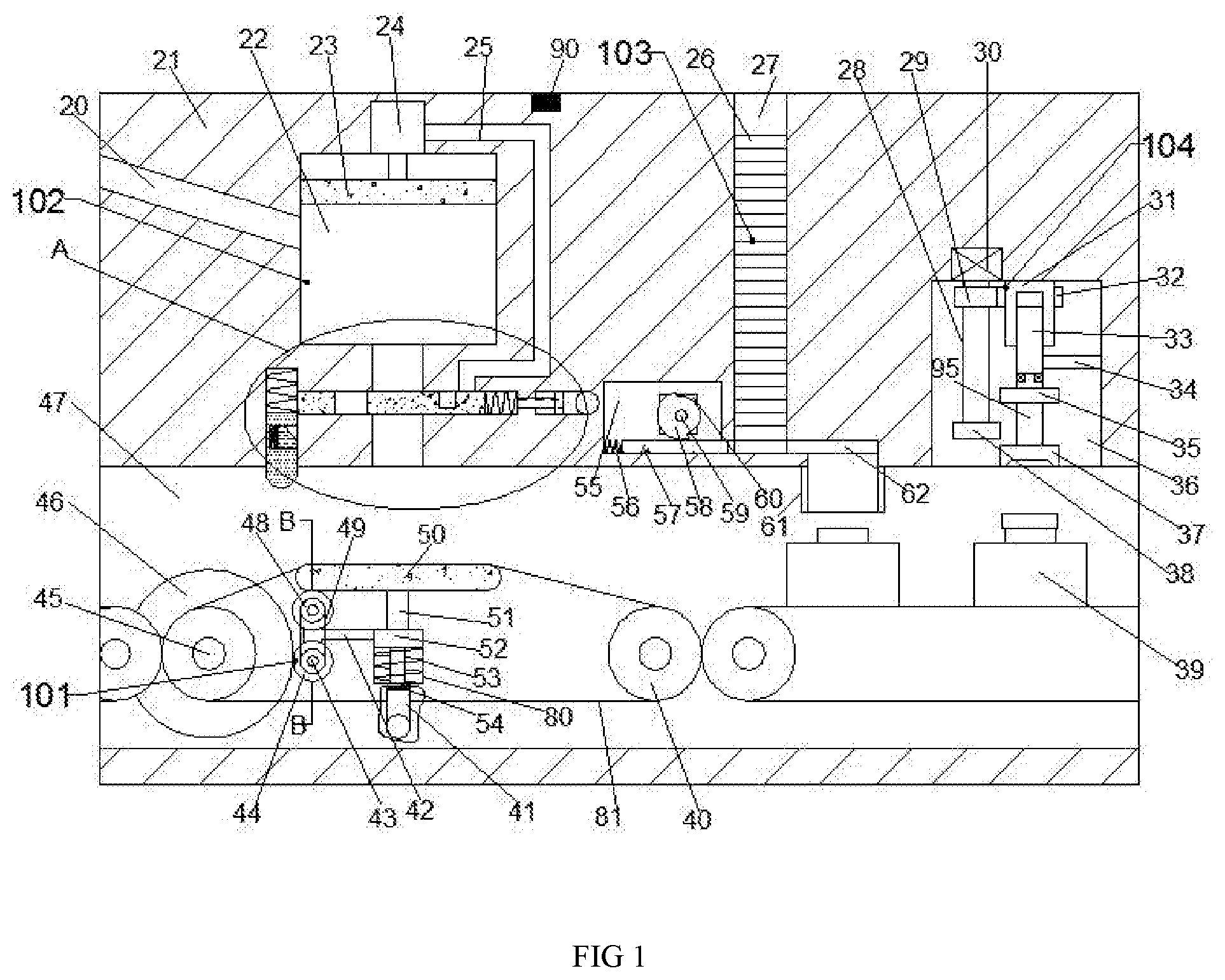
| Filed: | December 4, 2019 |
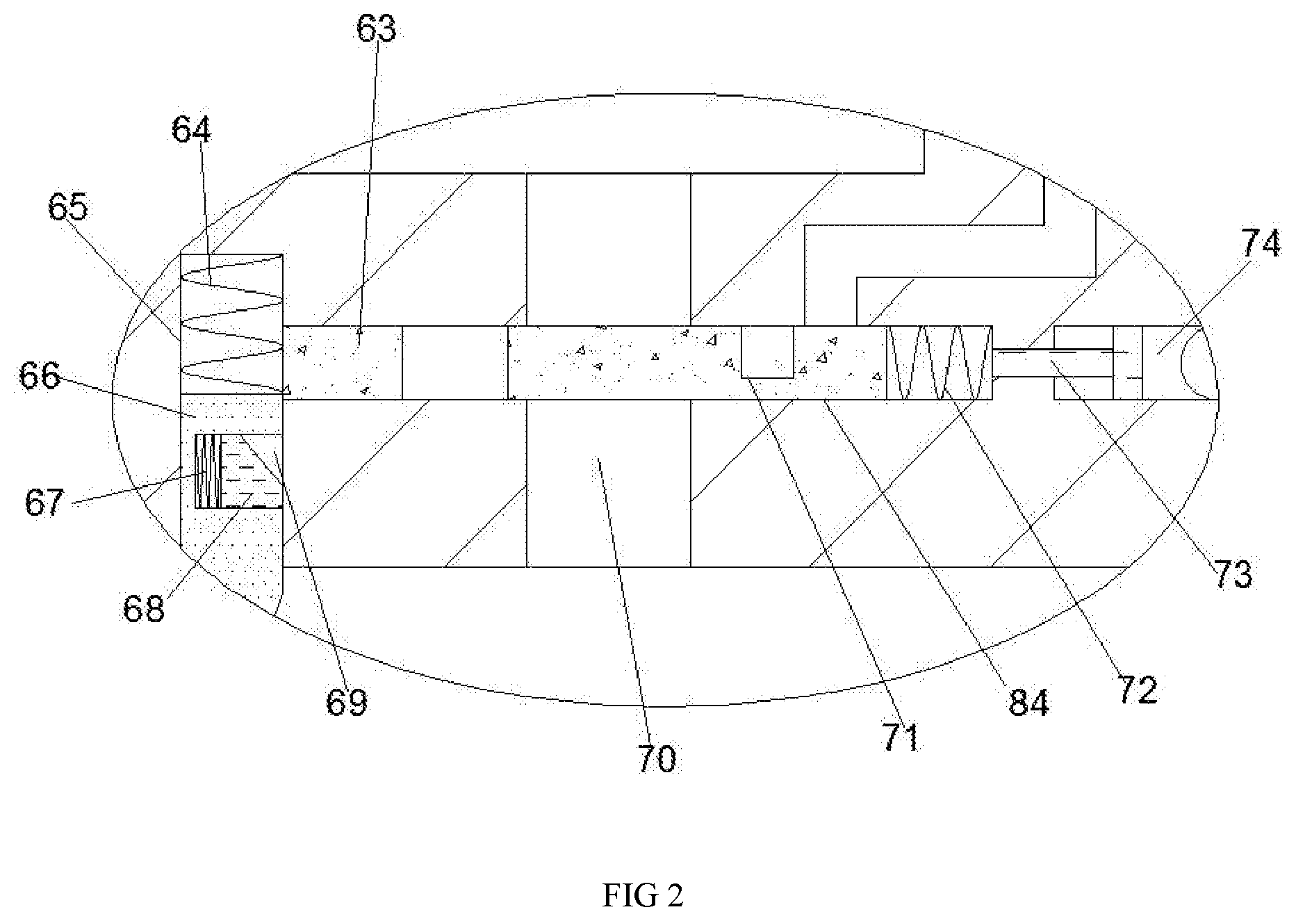
| Current U.S. Class: | 1/1 |
| Current CPC Class: | B65B 57/00 20130101; B65B 43/54 20130101; B65B 3/12 20130101; B65B 37/18 20130101; B65B 7/2835 20130101 |
| International Class: | B65B 37/18 20060101 B65B037/18; B65B 3/12 20060101 B65B003/12; B65B 7/28 20060101 B65B007/28; B65B 43/54 20060101 B65B043/54; B65B 57/00 20060101 B65B057/00 |
Foreign Application Data
| Date | Code | Application Number |
|---|---|---|
| Sep 28, 2019 | CN | 201910928644X |
Claims
1. An automatic canning device for canned food, comprising a body, characterized in that: the body is provided with a transport cavity penetrating the body, and a weighing device is provided in the transport cavity; the weighing device includes rotating shafts rotatably installed on the front and rear side walls of the transportation chamber, a large gear is fixed on the rotating shaft, and a long plate chute is provided on the rear side wall of the transportation chamber. The bottom side of the chute is provided with a hydraulic pipeline. A long plate is slidably connected to the long plate chute. A large spring is connected between the long plate and the long plate chute. The top surface of the long plate is fixed. There is a thin rod, a top plate is fixed on the top surface of the thin rod, and a T-shaped rod is fixed on the left side of the long plate. The front side of the T-shaped rod is symmetrically connected with a short axis up and down. A pinion is fixed on the short shaft, and a symmetrical pulley is also fixed on the short shaft. A small belt is connected between the two symmetrical pulleys, and the rear side of the short shaft is dynamically connected. There is a power motor fixedly connected to the front side of the T-shaped rod, the small gear can mesh with the large gear, the long plate extends downward into the hydraulic pipeline, and is in contact with the top of the hydraulic pipeline. The wall is slidably connected, the long plate is fixed with a lifting block in the hydraulic pipeline, and the top wall of the transport chamber is provided with a discharge pipe. The top wall of the discharge pipe is provided with a filling chamber, the left side wall of the filling chamber is provided with a joining pipe, the discharge pipe is provided with a traverse chute, and the left side wall of the traverse chute A trigger chute is provided, and an oil pipe communicating with the hydraulic pipeline is provided on the right side of the traverse chute; an adding device for adding jam is provided between the filling cavity and the traverse chute. An alignment block is fixed on the top wall of the transport cavity, and a translation cavity is connected to the top side of the inner wall of the alignment block. A pushing cavity is connected to the left side of the translation cavity. A cover groove is provided on the top wall of the translation cavity. A capping device is provided between the cover groove and the pushing cavity. A top wall of the transport cavity is provided. There is an opening cavity, and a tightening device for tightening the cover is provided in the opening cavity.
2. An automatic canning device for canned food according to claim 1, characterized in that: a transport pulley is provided in the transport cavity, and a transport belt is connected between the opposite transport pulleys, and The transport belt can transport glass bottles, wherein the transport belt on the middle side is slidably connected with the top surface of the top plate.
3. An automatic canning device for canned food according to claim 1, wherein the adding device comprises a hydraulic cylinder fixedly installed on the top wall of the filling cavity, A hydraulic plate slidingly connected to the filling cavity is connected to the bottom side, a trigger block is slidingly connected to the trigger chute, and a trigger spring is connected between the trigger block and the trigger chute. The trigger block A card block chute with an opening to the right is provided in the card block. A card block is slidably connected to the card block chute, and a block spring is connected between the card block and the card block chute. A switch plate is slidably connected in the middle, a compression spring is connected between the switch plate and the traverse chute, the clamping block can be snapped into the traverse chute, and a battery is provided in the switch plate. A T-shaped sliding rod is slidably connected to the oil pipe and the traverse chute, a hydraulic oil is provided between the T-shaped sliding rod and the lifting block, and a wire is symmetrically provided on the right side of the hydraulic cylinder. The other side of the electric wire can communicate with the battery.
4. An automatic canning device for canned food according to claim 1, wherein the capping device comprises a pushing motor fixedly installed on the rear side wall of the pushing cavity, and a gear is connected to the driving motor. A shaft, a sector gear is fixed on the gear shaft, a reset rack is slidably connected in the translation cavity, a reset spring is connected between the reset rack and the pushing cavity, and the cover slot is slidably connected There is a cap which can be screwed to the top side of the glass bottle.
5. An automatic canning device for canned food according to claim 4, wherein the tightening device comprises a driving motor fixedly installed on the top wall of the opening cavity, and power is connected to the driving motor. A first gear is fixed on the upper side of the power shaft, and a fourth gear is fixed on the lower side of the power shaft; a screw sleeve is rotatably connected to the top wall of the opening cavity; A second gear meshed with the first gear is fixedly fixed, a lifting screw is threadedly connected in the screw sleeve, and a limit position for sliding connection with the right wall of the opening cavity is fixed on the lifting screw. A slider, a rotation shaft is rotatably connected to the bottom side of the lifting screw, a third gear that can mesh with the fourth gear is fixed on the upper side of the rotation shaft, and a bottom side of the rotation shaft is fixed Tighten the pad.
6. An automatic canning device for canned food according to claim 3, characterized in that: the elastic force of the clamping block spring and the elastic force of the compression spring.
7. The automatic canning device for canned food according to claim 5, wherein the tightening pad is made of rubber material.
8. An automatic canning device for canned food according to claim 3, characterized in that: a controller is fixed on the top surface of the body, and the controller can drive the hydraulic cylinder to reset by a signal.
9. An automatic canning device for canned food according to claim 2, characterized in that: when the top plate is positioned at the top and bottom ends, the small gear is engaged with the large gear at this time.
Description
CROSS-REFERENCES TO RELATED APPLICATIONS
[0001] The present application claims priority from Chinese application No. 201910928644X filed on Sep. 28, 2019 which is hereby incorporated by reference in its entirety.
TECHNICAL FIELD
[0002] The invention relates to the field of food processing, in particular to an automatic canning device for canned food.
BACKGROUND OF THE INVENTION
[0003] With the improvement of people's living standards, more and more people like to eat jams, and the level of food processing has improved, so that jams can be stored for a long time. The existing packaging methods basically use assembly lines to process or produce Made by manual processing and adding;
[0004] Existing flow-through devices all use electrical control compared to mechanical devices, which have insufficient stability. Manually adding packaging jams by hand can easily cause problems such as insufficient packaging and different net jam contents.
BRIEF SUMMARY OF THE INVENTION
[0005] An object of the present invention is to provide an automatic canning device for canned food, so as to solve the problems raised in the background art described above.
[0006] In order to achieve the above object, the present invention provides the following technical solution: An automatic canning device for canned food, including a body, wherein the body is provided with a transportation cavity penetrating the body, and a weighing device is provided in the transportation cavity.
[0007] The weighing device includes rotating shafts rotatably installed on the front and rear side walls of the transportation chamber, a large gear is fixed on the rotating shaft, and a long plate chute is provided on the rear side wall of the transportation chamber. The bottom side of the chute is provided with a hydraulic pipeline. A long plate is slidably connected to the long plate chute. A large spring is connected between the long plate and the long plate chute. The top surface of the long plate is fixed. There is a thin rod, a top plate is fixed on the top surface of the thin rod, and a T-shaped rod is fixed on the left side of the long plate. The front side of the T-shaped rod is symmetrically connected with a short axis up and down. A pinion is fixed on the short shaft, and a symmetrical pulley is also fixed on the short shaft. A small belt is connected between the two symmetrical pulleys, and the rear side of the short shaft is dynamically connected. There is a power motor fixedly connected to the front side of the T-shaped rod, the small gear can mesh with the large gear, the long plate extends downward into the hydraulic pipeline, and is in contact with the top of the hydraulic pipeline. The wall is slidably connected, the long plate is fixed with a lifting block in the hydraulic pipeline, and the top wall of the transport chamber is provided with a discharge pipe. The top wall of the discharge pipe is provided with a filling chamber, the left side wall of the filling chamber is provided with a joining pipe, the discharge pipe is provided with a traverse chute, and the left side wall of the traverse chute A trigger chute is provided, and an oil pipe communicating with the hydraulic pipeline is provided on the right side of the traverse chute;
[0008] An adding device for adding jam is provided between the filling cavity and the traverse chute. An alignment block is fixed on the top wall of the transport cavity, and a translation cavity is connected to the top side of the inner wall of the alignment block. A pushing cavity is connected to the left side of the translation cavity. A cover groove is provided on the top wall of the translation cavity. A capping device is provided between the cover groove and the pushing cavity. A top wall of the transport cavity is provided. There is an opening cavity, and a tightening device for tightening the cover is provided in the opening cavity.
[0009] On the basis of the above technical solution, a transport pulley is provided in the transport cavity, and a transport belt is connected between the opposite transport pulleys. The transport belt can transport glass bottles, wherein the transport belt on the middle side and The top surface of the top plate is slidably connected.
[0010] On the basis of the above technical solution, the adding device includes a hydraulic cylinder fixedly installed on the top wall of the filling chamber, and a hydraulic plate slidingly connected to the filling chamber is connected to the bottom side of the hydraulic cylinder. A trigger block is slidably connected to the trigger chute, and a trigger spring is connected between the trigger block and the trigger chute. The trigger block is provided with a card block chute that opens to the right, and the card block A clamping block is slidably connected in the chute, a clamping block spring is connected between the clamping block and the clamping block chute, a switch plate is slidably connected in the traverse chute, and the switch plate and the traverse A compression spring is connected between the chute, the clamping block can be inserted into the traverse chute, a battery is installed in the switch plate, and a T-shaped slide is slidably connected to the oil pipe and the traverse chute. A hydraulic oil is provided between the T-shaped sliding rod and the lifting block, and a wire is symmetrically arranged on the right side of the hydraulic cylinder, and the other side of the wire can communicate with the battery.
[0011] On the basis of the above technical solution, the capping device includes a driving motor fixedly installed on a rear side wall of the driving cavity, and a gear shaft is dynamically connected to the driving motor, and a sector gear is fixed on the gear shaft, and the translation A reset rack is slidably connected in the cavity, a reset spring is connected between the reset rack and the pushing cavity, a lid is slidably connected in the lid groove, and the lid can be threaded with the top side of the glass bottle connection.
[0012] Based on the above technical solution, the tightening device includes a driving motor fixedly installed on the top wall of the opening cavity, and a driving shaft is dynamically connected to the driving motor, and a first gear is fixed on the upper side of the driving shaft. A fourth gear is fixed on the lower side of the power shaft, and a screw sleeve is rotatably connected to the top wall of the opening cavity, and a second gear meshing with the first gear is fixed on the screw sleeve. A lifting screw is threadedly connected to the screw sleeve, and a limit slider slidingly connected to the right side wall of the opening cavity is fixed on the lifting screw. A rotating shaft is rotatably connected to the bottom side of the lifting screw. A third gear that can mesh with the fourth gear is fixed on the upper side of the rotating shaft, and a tightening pad is fixed on the bottom side of the rotating shaft.
[0013] On the basis of the above technical solution, the elastic force of the clamping spring and the elastic force of the compression spring.
[0014] Based on the above technical solution, the tightening pad is made of rubber material.
[0015] Based on the above technical solution, a controller is fixed on the top surface of the machine body, and the controller can drive the hydraulic cylinder to reset upward by a signal.
[0016] Based on the above technical solution, when the top plate is located at the top and bottom ends, the small gear is meshed with the large gear.
[0017] In summary, the present invention has the beneficial effect that the device can add jam to the glass jar through a mechanical structure. Compared to manually adding jam, the content of the jam added by the device can be kept consistent, so that the standardization of the product can be obtained. Guarantee
[0018] At the same time, the device can automatically seal and tighten glass bottles, so that the device can automatically produce and process jams, and at the same time use a machine to tighten, which can improve the tightness of the glass bottles, thereby extending the shelf life of the jam.
BRIEF DESCRIPTION OF THE DRAWINGS
[0019] In order to more clearly illustrate the embodiments of the invention or the technical solutions in the prior art, the drawings used in the description of the embodiments or the prior art will be briefly introduced below. Obviously, the drawings in the following description are merely For some embodiments of the invention, for those skilled in the art, other drawings can be obtained based on these drawings without paying creative labor.
[0020] FIG. 1 is a schematic front view of a full-scale sectional structure of an automatic canning device for canned food according to the present invention; FIG.
[0021] FIG. 2 is a partially enlarged view of A in FIG. 1 of the present invention; FIG.
[0022] FIG. 3 is a sectional view taken along the line B-B in FIG. 1 of the present invention.
DETAILED DESCRIPTION OF THE INVENTION
[0023] All features disclosed in this specification, or all disclosed methods or steps, other than mutually exclusive features and/or steps, may be combined in any manner.
[0024] Any feature disclosed in this specification (including any additional claims, abstract, and drawings), unless specifically stated, may be replaced by other equivalent or similar purpose alternative features. That is, unless specifically stated, each feature is just one example of a series of equivalent or similar features.
[0025] The present invention will be described in detail below with reference to FIGS. 1-3. Among them, for convenience of description, the orientation described below is defined as follows: the up-down, left-right, left-back, and up-down directions described below are consistent with the front-back, left-right, up, down, and down directions of the view in FIG. 1 is a front view of the device of the present invention, and the direction shown in FIG. 1 is the same as the front, rear, left, right, and up and down directions of the device of the present invention.
[0026] 1-3, an embodiment of the present invention provides an automatic canning device for canned food, which includes a body 21, and the body 21 is provided with a transport cavity 47 through which the body 21 passes. A weighing device 101 is provided in the transport cavity 47, and the weighing device 101 includes a rotation shaft 45 rotatably installed on the front and rear side walls of the transportation cavity 47, and a large gear 46 is fixed on the rotation shaft 45. The rear side wall of the cavity 47 is provided with a long plate chute 80, and a bottom side of the long plate chute 80 is provided with a hydraulic pipe 41. A long plate 52 is slidably connected to the long plate chute 80, and the long plate 52 A large spring 53 is connected between the long plate chute 80, and a thin rod 51 is fixed on the top surface of the long plate 52. A top plate 50 is fixed on the top surface of the thin rod 51. The left side of 52 is fixed with a T-shaped rod 42. The front side of the T-shaped rod 42 is symmetrically connected with a short shaft 43 vertically. The short shaft 43 is respectively fixed with a pinion 44 and the short shaft 43. A symmetrical belt pulley 48 is also fixed on the upper side, and a small belt 49 is connected between the two symmetrical belt pulleys 48. The rear side of the lower shaft 43 is dynamically connected to the front side of the T-shaped rod 42. solid The connected power motor 82, the small gear 44 can mesh with the large gear 46, the long plate 52 extends downward into the hydraulic pipe 41, and is slidably connected to the top wall of the hydraulic pipe 41, The long plate 52 is fixed with a lifting block 54 in the hydraulic pipeline 41, a discharge pipe 70 is provided on the top wall of the transport chamber 47, and a filling chamber 22 is provided on the top wall of the discharge pipe 70. The left side wall of the filling cavity 22 is provided with a joining pipe 20, and the discharge pipe 70 is provided with a traverse chute 84. The left side wall of the traverse chute 84 is provided with a trigger chute 65. An oil pipe 74 communicating with the hydraulic pipeline 41 is provided on the right side of the traverse chute 84, and an adding device 102 for adding jam is provided between the filling cavity 22 and the traverse chute 84. An alignment block 61 is fixed on the top wall of the transport cavity 47. A translation cavity 62 is communicated on the top side of the inner wall of the alignment block 61, and a pushing cavity 55 is communicated on the left side of the translation cavity 62. A cover groove 27 is provided on the top wall, and a capping device 103 is provided between the cover groove 27 and the pushing cavity 55. An opening cavity 36 is provided on the top wall of the transport cavity 47, and an opening cavity 36 is provided in the opening cavity 36. Tightening means for tightening the lid 104 to.
[0027] In addition, in one embodiment, a transport pulley 40 is provided in the transport cavity 47, and a transport belt 81 is connected between the opposite transport pulleys 40. The transport belt 81 can transport glass bottles 39, among which The transport belt 81 on the side is slidably connected to the top surface of the top plate 50.
[0028] In addition, in one embodiment, the adding device 102 includes a hydraulic cylinder 24 fixedly mounted on the top wall of the filling chamber 22, and a bottom side of the hydraulic cylinder 24 is dynamically connected with the filling chamber. 22 A hydraulic plate 23 slidingly connected, a trigger block 66 is slidingly connected to the trigger chute 65, and a trigger spring 64 is connected between the trigger block 66 and the trigger chute 65. The trigger block 66 is provided with A card block chute 69 with a rightward opening is slidably connected with a card block 68, and a block spring 67 is connected between the card block 68 and the card block chute 69. A switch plate 63 is slidably connected to the sliding slot 84. A compression spring 72 is connected between the switching plate 63 and the horizontal sliding slot 84. The clamping block 68 can be inserted into the horizontal sliding slot 84. A battery 71 is provided in the switch board 63, a T-shaped slide bar 73 is slidably connected to the oil pipe 74 and the traverse slide slot 84, and a space is provided between the T-shaped slide bar 73 and the lifting block 54 For hydraulic oil, an electric wire 25 is symmetrically arranged on the right side of the hydraulic cylinder 24, and the other side of the electric wire 25 can communicate with the battery 71, so that when the glass bottle 39 is driven When the triggering block 66 moves upward, the clamping block 68 is caught in the traverse chute 84, thereby driving the switch plate 63 to move to the right, so that the switch plate 63 and the discharge material The pipe 70 is connected, and at this time, the battery 71 is connected to the electric wire 25, so that the hydraulic cylinder 24 is activated, and the hydraulic plate 23 is pushed down to squeeze the jam in the hydraulic plate 23 into the place. Mentioned glass bottle 39.
[0029] In addition, in one embodiment, the capping device 103 includes a pushing motor 60 fixedly mounted on the rear side wall of the pushing cavity 55. A gear shaft 59 is dynamically connected to the pushing motor 60, and the gear shaft 59 is fixed on the gear shaft 59. There is a sector gear 58, a reset rack 57 is slidably connected to the translation cavity 62, a reset spring 56 is connected between the reset rack 57 and the pushing cavity 55, and a cover is slidably connected to the cover groove 27. 26. The cover 26 may be threadedly connected to the top side of the glass bottle 39, so as to open the pushing motor 60, thereby driving the gear shaft 59 and the sector gear 58 to rotate, thereby driving the reset rack 57 Move to the right to push the cover 26 on the bottom side out of the translation cavity 62, so as to drop onto the glass bottle 39 on the bottom side of the translation cavity 62.
[0030] In addition, in one embodiment, the tightening device 104 includes a driving motor 30 fixedly mounted on the top wall of the opening cavity 36, and a driving shaft 28 is dynamically connected to the driving motor 30, and an upper side of the driving shaft 28 A first gear 29 is fixed, a fourth gear 38 is fixed on the lower side of the power shaft 28, a screw sleeve 31 is rotatably connected to the top wall of the opening cavity 36, and a screw sleeve 31 is fixed on the screw shaft 31. A second gear 32 meshed with the first gear 29, a lifting screw 33 is screwed into the lead screw sleeve 31, and the lifting screw 33 is fixed on the sliding screw 33 to be connected to the right side wall of the opening cavity 36. A limiting shaft 34 is provided. A rotating shaft 95 is rotatably connected to the bottom side of the lifting screw 33. A third gear 35 is fixed on the upper side of the rotating shaft 95 and can be engaged with the fourth gear 38. A tightening pad 37 is fixed on the bottom side of the rotating shaft 95, so that the driving motor 30 is turned on, thereby driving the power shaft 28, the first gear 29, and the fourth gear 38 to rotate, thereby driving the second gear. 32 and the lead screw sleeve 31 rotate, thereby driving the lifting screw 33 and the limit slider 34 to move downward, so that The third gear 35 meshes with the fourth gear 38. At this time, the fourth gear 38 drives the third gear 35, the rotating shaft 95, and the tightening pad 37 to rotate, so that the tightening pad The cap 26 on the glass bottle 39 on the lower side of 37 is tightened.
[0031] In addition, in one embodiment, the elastic force of the block spring 67 and the elastic force of the compression spring 72.
[0032] In addition, in one embodiment, the tightening pad 37 is made of rubber material, which can effectively drive the cover 26 to rotate.
[0033] In addition, in one embodiment, a controller 90 is fixed on the top surface of the body 21, and the controller 90 can drive the hydraulic cylinder 24 to reset upward by a signal.
[0034] In addition, in one embodiment, when the top plate 50 is at the top and bottom ends, the small gear 44 is meshed with the large gear 46 at this time.
[0035] In the initial state, jam is added to the filling cavity 22 through the adding pipe 20, and a lid is added to the cover groove 27. The top surface of the top plate 50 is not.
[0036] When adding jam to the glass bottle 39, the power motor 82 is turned on, so that the large gear 46, the small gear 44, and the symmetrical pulley 48 are rotated, so that the middle-side transportation pulley 40 and the transportation belt 81 are rotated, thereby driving The glass bottle 39 moves to the right. When the glass bottle 39 is located on the top surface of the top plate 50, the top plate 50 is moved downward. At this time, the lower pinion 44 and the large gear 46 are disengaged. At this time, the glass bottle 39 triggers the trigger. When the block 66 moves upward, the clamping block 68 is caught in the traverse chute 84, so that the switch plate 63 is moved to the right, so that the switch plate 63 is connected to the discharge pipe 70. At this time, the battery 71 and the wire 25 are connected. Turn on to start the hydraulic cylinder 24, drive the hydraulic plate 23 to squeeze down, squeeze the jam in the hydraulic plate 23 into the glass bottle 39, and when the jam in the glass bottle 39 is full, drive the thin rod 51, the long plate 52 Move the lifting block 54 downward. At this time, the small gear 44 on the upper side meshes with the large gear 46. At this time, the long plate 52 drives the lifting block 54 to move downward, thereby driving the T-shaped slide bar 73 to the left through the hydraulic oil, and the switch The plate 63 is pushed to the left, thereby pushing the block 68 back to the trigger slot 65 Triggering block 66 by the trigger spring 64 is reset, when the transport belt 81 to drive the movement of the glass 39 of the right side of the transport pulley 40;
[0037] When the glass bottle 39 is aligned with the translation cavity 62, the pushing motor 60 is turned on, thereby driving the gear shaft 59 and the sector gear 58 to rotate, thereby driving the reset rack 57 to move to the right, and pushing the bottom most cover 26 out of the translation cavity. 62, thereby dropping onto the glass bottle 39 on the bottom side of the translation cavity 62;
[0038] When the glass bottle 39 is aligned with the tightening pad 37, the driving motor 30 is turned on, thereby driving the power shaft 28, the first gear 29 and the fourth gear 38 to rotate, thereby driving the second gear 32 and the screw sleeve 31 to rotate, thereby driving The lifting screw 33 and the limit slider 34 move downward, so that the third gear 35 meshes with the fourth gear 38. At this time, the fourth gear 38 drives the third gear 35, the rotation shaft 95 and the tightening pad 37 to rotate, thereby The cap 26 on the glass bottle 39 under the tightening pad 37 is tightened.
[0039] The beneficial effect of the present invention is that the device can add jam to the glass jar through a mechanical structure. Compared with manually adding jam, the content of the jam added by the device can be kept consistent, so that the standardization of the product can be guaranteed;
[0040] At the same time, the device can automatically seal and tighten glass bottles, so that the device can automatically produce and process jams, and at the same time use a machine to tighten, which can improve the tightness of the glass bottles, thereby extending the shelf life of the jam.
[0041] The above are only specific embodiments of the invention, but the scope of protection of the invention is not limited to this. Any changes or substitutions that are not thought through without creative work should be covered by the scope of protection of the invention. Therefore, the protection scope of the invention shall be subject to the protection scope defined by the claims.
* * * * *
D00000
D00001
D00002
D00003
XML
uspto.report is an independent third-party trademark research tool that is not affiliated, endorsed, or sponsored by the United States Patent and Trademark Office (USPTO) or any other governmental organization. The information provided by uspto.report is based on publicly available data at the time of writing and is intended for informational purposes only.
While we strive to provide accurate and up-to-date information, we do not guarantee the accuracy, completeness, reliability, or suitability of the information displayed on this site. The use of this site is at your own risk. Any reliance you place on such information is therefore strictly at your own risk.
All official trademark data, including owner information, should be verified by visiting the official USPTO website at www.uspto.gov. This site is not intended to replace professional legal advice and should not be used as a substitute for consulting with a legal professional who is knowledgeable about trademark law.