Rotatable Folding Diving Mask
Wung; Chin-Hsien
U.S. patent application number 16/147890 was filed with the patent office on 2020-04-02 for rotatable folding diving mask. The applicant listed for this patent is Dongguan Longwell Sports Co., Ltd.. Invention is credited to Chin-Hsien Wung.
| Application Number | 20200102059 16/147890 |
| Document ID | / |
| Family ID | 69947080 |
| Filed Date | 2020-04-02 |


View All Diagrams
| United States Patent Application | 20200102059 |
| Kind Code | A1 |
| Wung; Chin-Hsien | April 2, 2020 |
ROTATABLE FOLDING DIVING MASK
Abstract
A rotatable folding diving mask includes a mask, a snorkel, and an elastic binding strap. By connecting the snorkel and the mask through a rotating shaft and combining with the structural design of a control button, a rotating and folding structure is provided, and the operation is simple and it is easy to fold, thereby achieving the purpose of reducing the occupied space. The elastic binding strap is connected to the mask through a buckle connection structure, so that the elastic binding strap can be easily disassembled and replaced, and the structure is simple and ingenious.
| Inventors: | Wung; Chin-Hsien; (Dongguan City, CN) | ||||||||||
| Applicant: |
|
||||||||||
|---|---|---|---|---|---|---|---|---|---|---|---|
| Family ID: | 69947080 | ||||||||||
| Appl. No.: | 16/147890 | ||||||||||
| Filed: | October 1, 2018 |
| Current U.S. Class: | 1/1 |
| Current CPC Class: | B63C 11/16 20130101; B63C 2011/128 20130101 |
| International Class: | B63C 11/16 20060101 B63C011/16 |
Claims
1. A rotatable folding diving mask, comprising a mask, a snorkel, and an elastic binding strap; the snorkel being rotatably connected to an upper end of a front side of the mask in a foldable manner, the elastic binding strap being detachably connected to a rear side of the mask; the mask being provided with a first connecting portion for connecting the snorkel, the snorkel being provided with a second connecting portion for connecting the mask, the first connecting portion and the second connecting portion being connected through a rotating shaft; one side of the first connecting portion being provided with a control button for controlling the snorkel to be rotated and folded, one side of the second connecting portion being provided with a positioning recess, one end of the control button having a positioning buckle; wherein when the snorkel is in an unfolded state, the positioning buckle is positioned in the positioning recess; wherein when the snorkel is to be folded, the control button is pressed and then the positioning buckle is disengaged from the positioning recess, and the snorkel can be rotated and folded into a cavity at the rear side of the mask through the rotating shaft; the elastic binding strap being provided with a connecting buckle for connecting the mask, the mask being provided with a locating buckle for connecting the elastic binding strap, the connecting buckle being mated with the locating buckle.
2. The rotatable folding diving mask as claimed in claim 1, wherein the control button includes a press portion and a linkage portion; the linkage portion is rotatably connected to the mask through a positioning shaft; one side of the press portion is convexly provided with a stroke protrusion, the linkage portion is formed with a stroke groove, the stroke protrusion is movably fitted in the stroke groove; the positioning buckle is disposed on the linkage portion; when the press portion is pressed toward the snorkel, the press portion moves toward the snorkel and links the stroke projection to displace in the stroke groove, the linkage portion is rotated by the press portion, and the positioning buckle is disengaged from the positioning recess by rotation of the linkage portion.
3. The rotatable folding diving mask as claimed in claim 2, wherein the press portion is provided with a limiting protrusion, the limiting protrusion is located at one side of the stroke protrusion; the linkage portion is provided with a first limiting slot and a second limiting slot, the first limiting slot and the second limiting slot are spaced apart from each other, the first limiting slot is disposed farther away from the positioning buckle than the second limiting slot; the linkage portion is provided with a stopping portion; when the snorkel is in the unfolded state, the limiting protrusion is confined in the first limiting slot, and the press portion is limited to an outer surface of the mask and cannot act on the linkage portion; when the snorkel is to be folded, the press portion is pressed, and the limiting protrusion is displaced toward the snorkel with the press portion until the limiting protrusion is confined in the second limiting slot, one end of the stroke protrusion is limited to one side of the stopping portion, the press portion stops displacement, the press portion is disengaged from restriction of the mask, the linkage portion is rotated by the press portion, and the positioning buckle is disengaged from the positioning recess by the rotation of the linkage portion.
4. The rotatable folding diving mask as claimed in claim 2, wherein the linkage portion further has an elastic rotation support portion for supporting the rotation of the linkage portion, the elastic rotation support portion and the positioning buckle are disposed at two ends of the linkage portion respectively, and the stroke groove is located between the elastic rotation support portion and the positioning buckle.
5. The rotatable folding diving mask as claimed in claim 4, wherein the elastic rotation support portion is an arc-shaped elastic portion, and the arc-shaped elastic portion is curved outward from one side of the linkage portion.
6. The rotatable folding diving mask as claimed in claim 1, wherein the locating buckle is detachably connected to the mask; the locating buckle has an elastic engaging block, the elastic engaging block has an engaging block body and an elastic buckle arm connected to the engaging block body; the mask is formed with an engaging hole, one side of the engaging hole communicates with a barb groove; the elastic engaging block is detachably fitted into the engaging hole, the engaging block body is fitted into the engaging hole, and the elastic buckle arm is engaged in the barb groove.
7. The rotatable folding diving mask as claimed in claim 1, wherein the mask includes a mask frame, a mask pad and a mask lens, the mask pad and the mask lens are mounted on the mask frame; the mask frame has an air groove, the mask pad has a sealing wall, the mask lens has a first connecting wall and a second connecting wall, the second connecting wall extends outward from an outer side of the first connecting wall; the sealing wall is located between the mask frame and the first connecting wall; an inner side of the sealing wall is in close contact with the outer side of the first connecting wall, one end of the sealing wall is connected to the second connecting wall, one end of the second connecting wall is connected to the mask frame, and an outer side of the sealing wall seals the air groove to form an air passage.
8. The rotatable folding diving mask as claimed in claim 1, wherein the mask has a first mounting trough, the snorkel has a second mounting trough; one end of the control button is mounted in the first mounting trough, another end of the control button extends into the second mounting trough; and the positioning recess is formed in the second mounting trough.
9. The rotatable folding diving mask as claimed in claim 8, wherein the first connecting portion has a first connecting hole, the second connecting portion has a second connecting hole, the first connecting hole and the second connecting hole are connected through the rotating shaft; the first mounting trough and the second mounting trough are located at opposite sides of the first connecting hole and the second connecting, respectively.
Description
BACKGROUND OF THE INVENTION
1. Field of the Invention
[0001] The present invention relates to a mask, and more particularly to a rotatable folding diving mask.
2. Description of the Prior Art
[0002] With the demand for various sports, diving has become one of the emerging sports loved by more and more people. When diving, people would like to see the scenery underwater. Therefore, it is possible to wear a diving mask for breathing and watching underwater scenery.
[0003] A conventional diving mask includes a mask and a snorkel. In order to make the diving mask easy to carry and reduce the occupied space, the snorkel and the mask are usually connected by a plug-in structure. This plug-in connection structure leads to poor waterproof performance, and the snorkel is easy to fall and lose to affect the carrying. The diving mask also includes an elastic strap. In the prior art, the elastic strap is generally fastened to the mask, which makes the disassembly and replacement inconvenient.
[0004] In order to enable people to breathe smoothly under water, an air passage for breathing is arranged between the mask and the snorkel. The air passage in the prior art is usually arranged by using a tube structure. A single sealed tube is used to form the air passage, which occupies larger space and needs more production materials. In some masks, the air passage is surrounded by a plurality of structures. However, the connection structure is complicated, and the sealing of the air passage is poor. After a period of time, the air passage for breathing may be unsatisfactory and affect the use.
[0005] Accordingly, the inventor of the present invention has devoted himself based on his many years of practical experiences to solve these problems.
SUMMARY OF THE INVENTION
[0006] In view of the drawbacks of the prior art, the primary object of the present invention is to provide a rotatable folding diving mask, which is easy to operate and fold, reduces the occupied space, and is easy to disassemble and replace an elastic binding strap. Besides, its structural design is ingenious, the layout is clever, and it has better sealing effect.
[0007] In order to achieve the above object, the present invention adopts the following technical solutions.
[0008] A rotatable folding diving mask comprises a mask, a snorkel, and an elastic binding strap. The snorkel is rotatably connected to an upper end of a front side of the mask in a foldable manner. The elastic binding strap is detachably connected to a rear side of the mask.
[0009] The mask is provided with a first connecting portion for connecting the snorkel. The snorkel is provided with a second connecting portion for connecting the mask. The first connecting portion and the second connecting portion are connected through a rotating shaft.
[0010] One side of the first connecting portion is provided with a control button for controlling the snorkel to be rotated and folded. One side of the second connecting portion is provided with a positioning recess. One end of the control button has a positioning buckle. When the snorkel is in an unfolded state, the positioning buckle is positioned in the positioning recess. When the snorkel is to be folded, the control button is pressed and then the positioning buckle is disengaged from the positioning recess, and the snorkel can be rotated and folded into a cavity at the rear side of the mask through the rotating shaft.
[0011] The elastic binding strap is provided with a connecting buckle for connecting the mask. The mask is provided with a locating buckle for connecting the elastic binding strap. The connecting buckle is mated with the locating buckle.
[0012] Compared with the prior art, the present invention has obvious advantages and beneficial effects. Specifically, it can be known from the above technical solutions that by connecting the snorkel and the mask through the rotating shaft and combining with the structural design of the control button, the rotating and folding structure is provided, and the operation is simple and easy to fold, thereby achieving the purpose of reducing the occupied space. The elastic binding strap is connected to the mask through the buckle connection structure, so that the elastic binding strap can be easily disassembled and replaced, and the structure is simple and ingenious.
BRIEF DESCRIPTION OF THE DRAWINGS
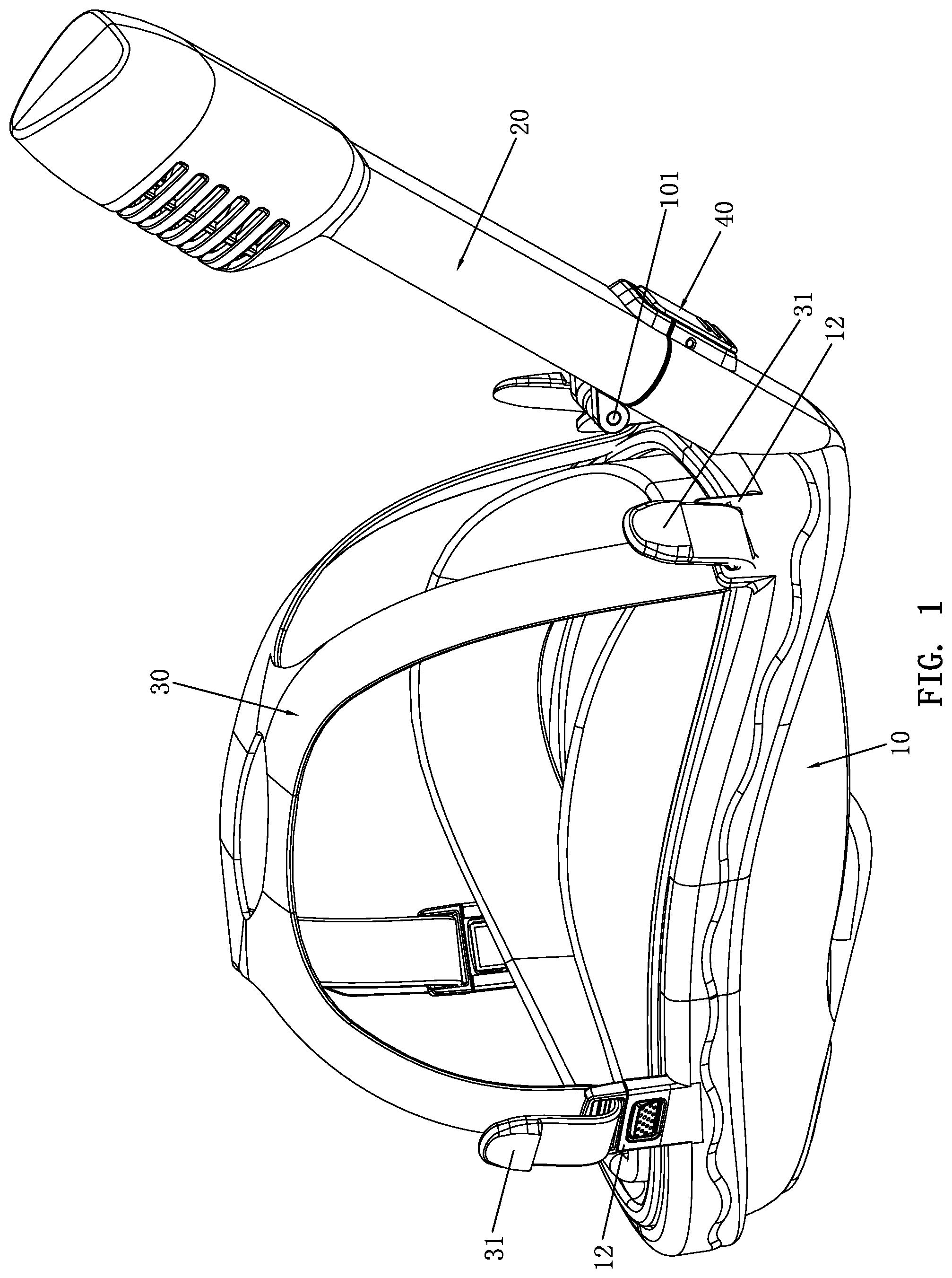
[0013] FIG. 1 is a perspective view according to an embodiment of the present invention;
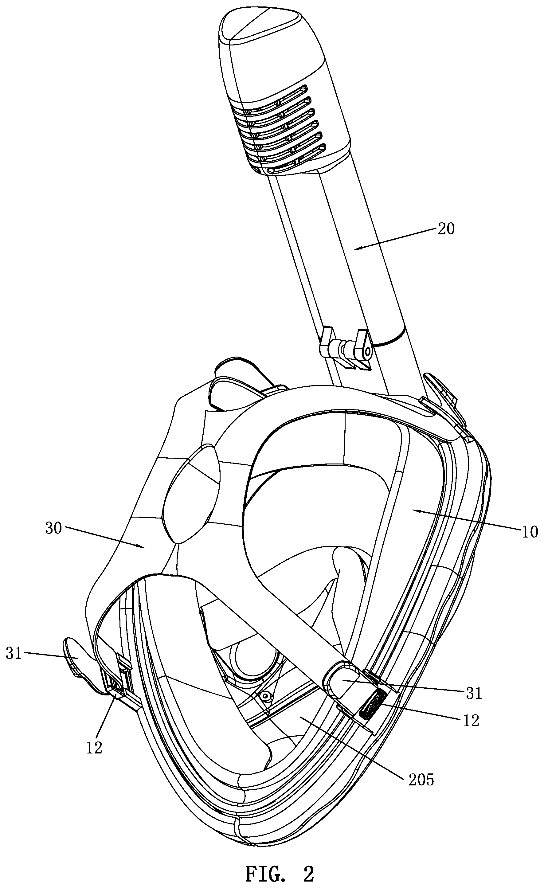
[0014] FIG. 2 is another perspective view according to the embodiment of the present invention;
[0015] FIG. 3 is an exploded view according to the embodiment of the present invention;
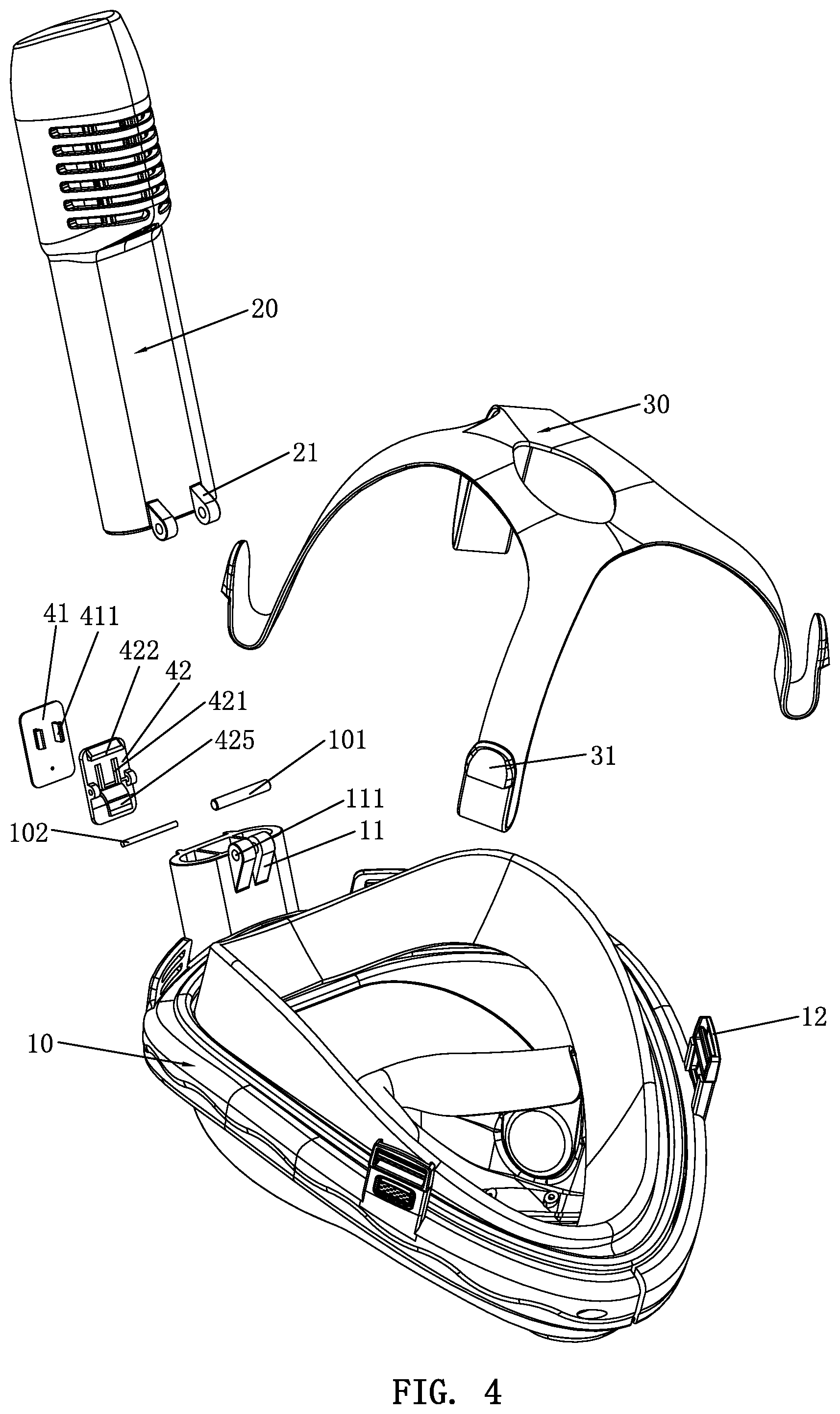
[0016] FIG. 4 is another exploded view according to the embodiment of the present invention;
[0017] FIG. 5 is a sectional view according to the embodiment of the present invention;
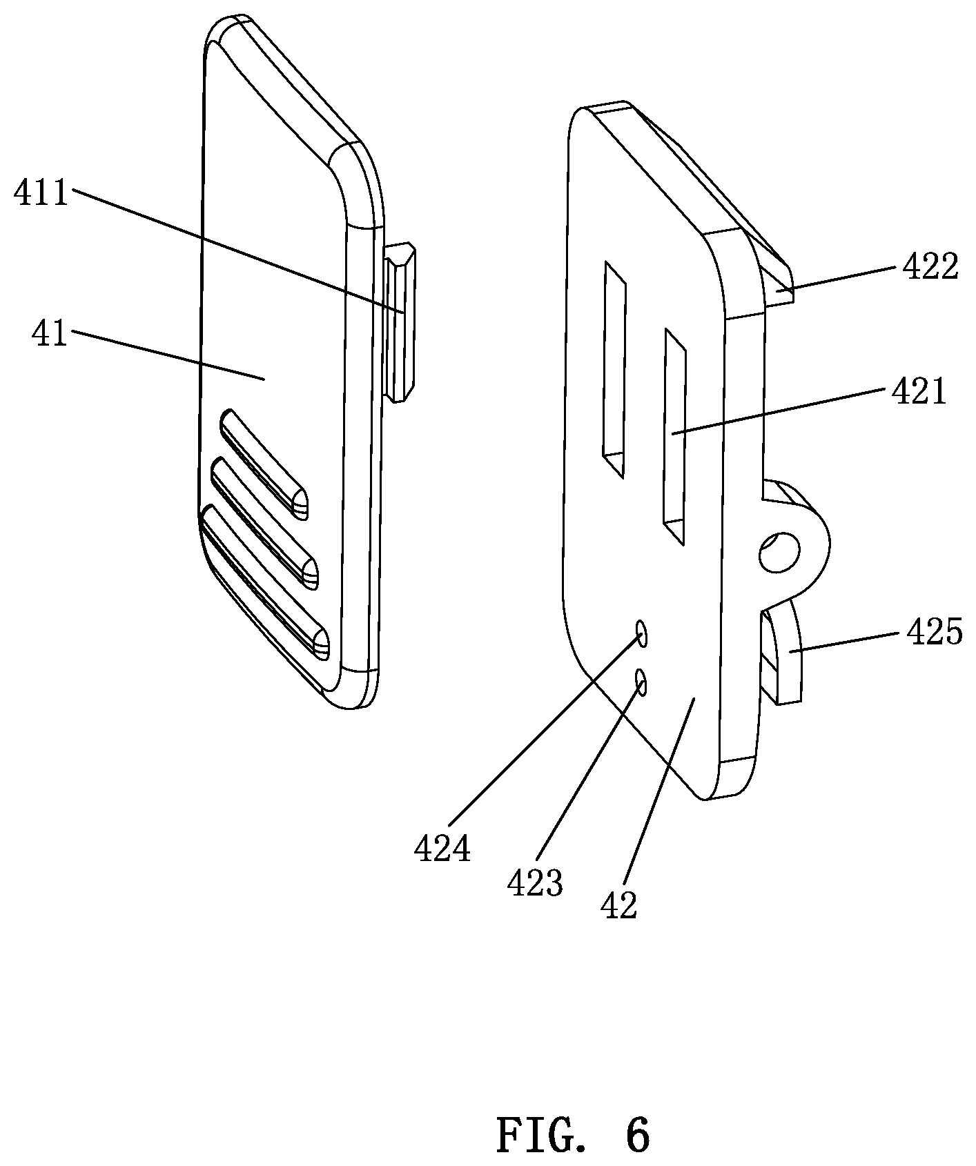
[0018] FIG. 6 is an exploded view of the control button according to the embodiment of the present invention;
[0019] FIG. 7 is another exploded view of the control button according to the embodiment of the present invention;
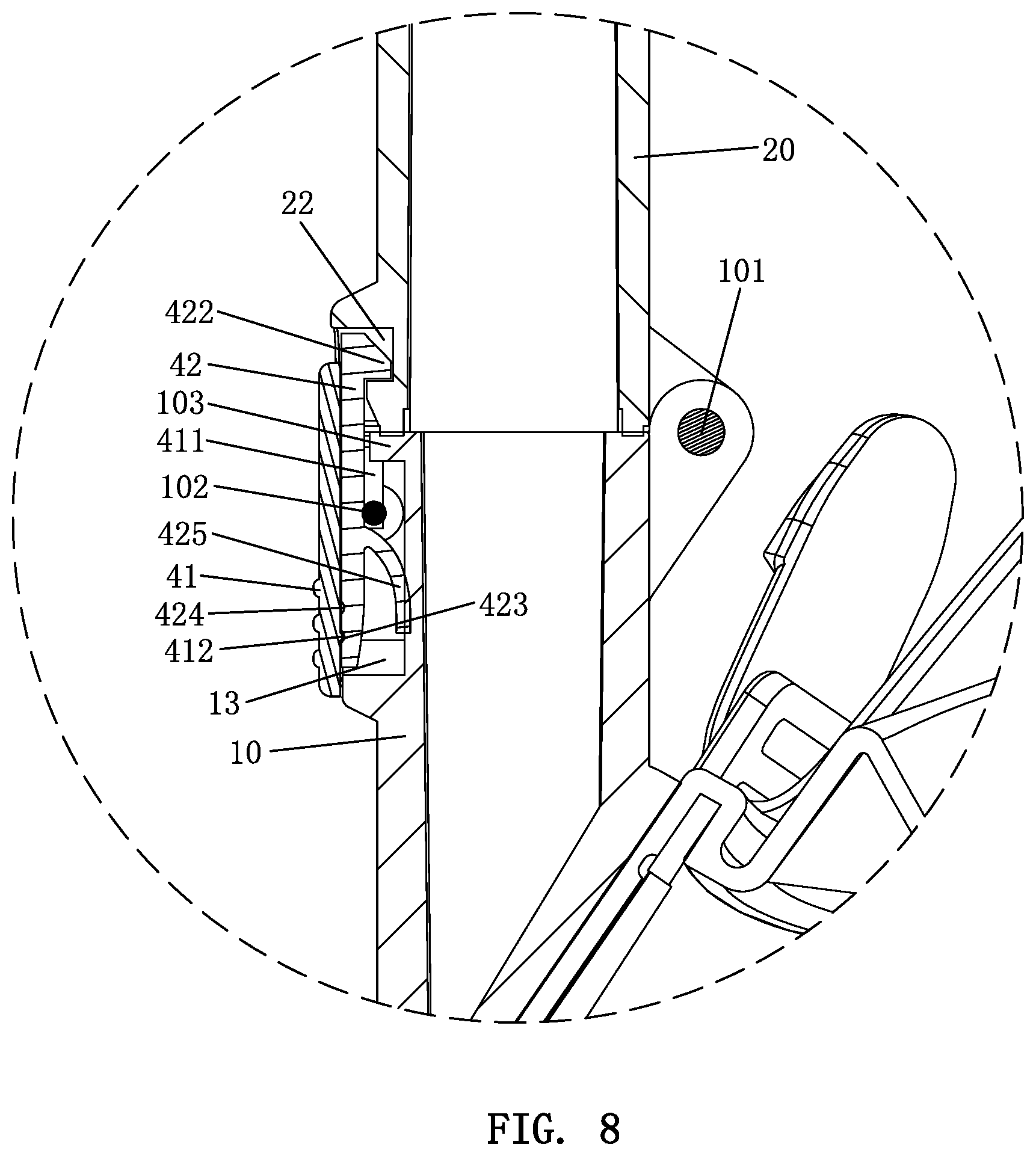
[0020] FIG. 8 is a partially sectional view according to the embodiment of the present invention;
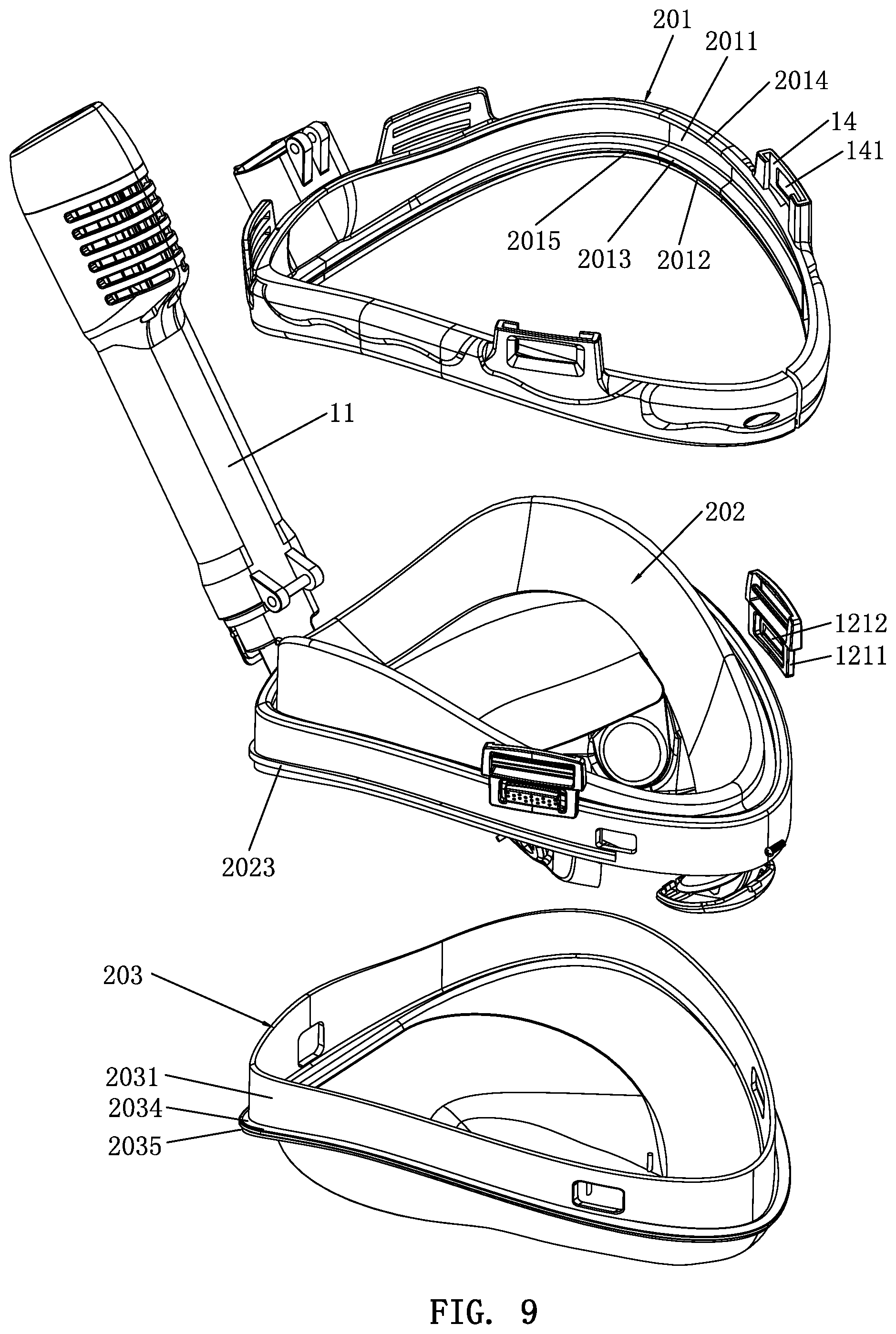
[0021] FIG. 9 is a further exploded view according to the embodiment of the present invention;
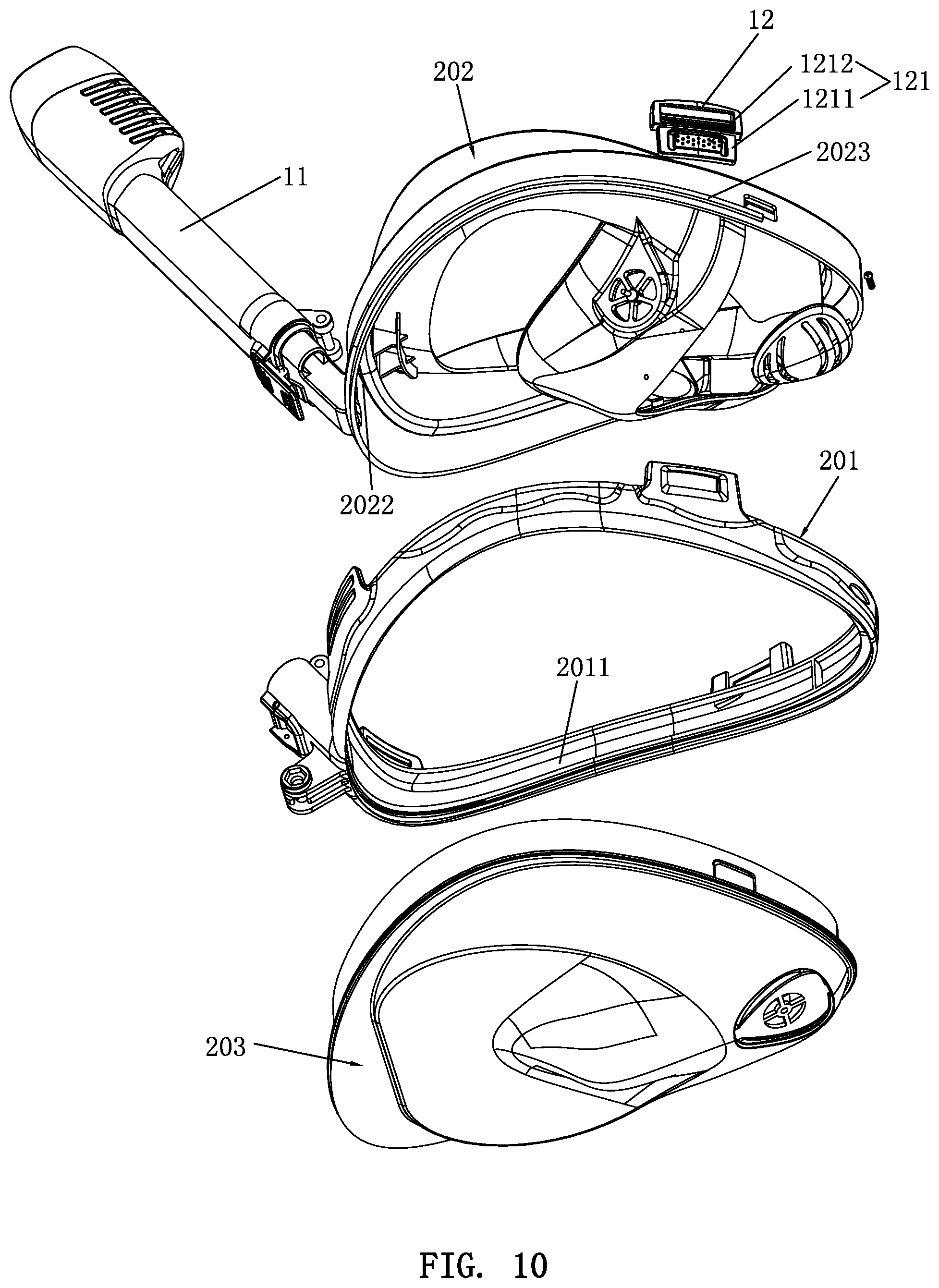
[0022] FIG. 10 is still a yet further exploded view according to the embodiment of the present invention;
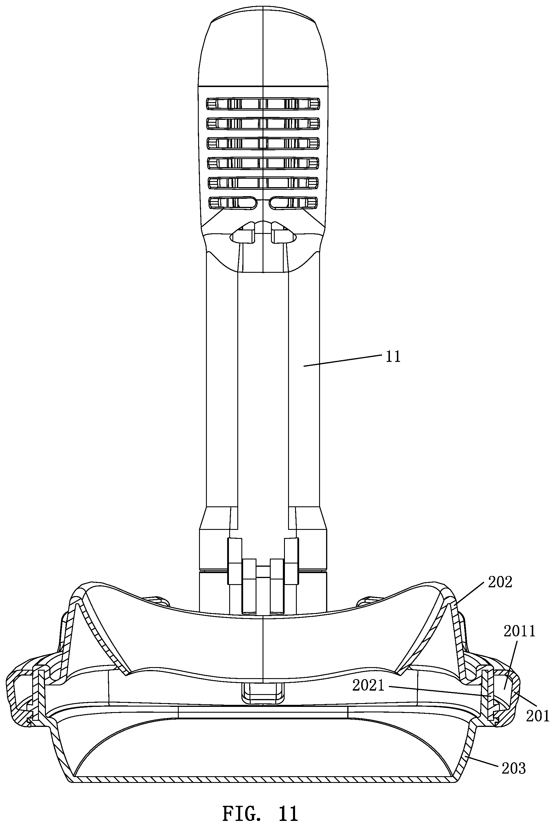
[0023] FIG. 11 is another sectional view according to the embodiment of the present invention; and
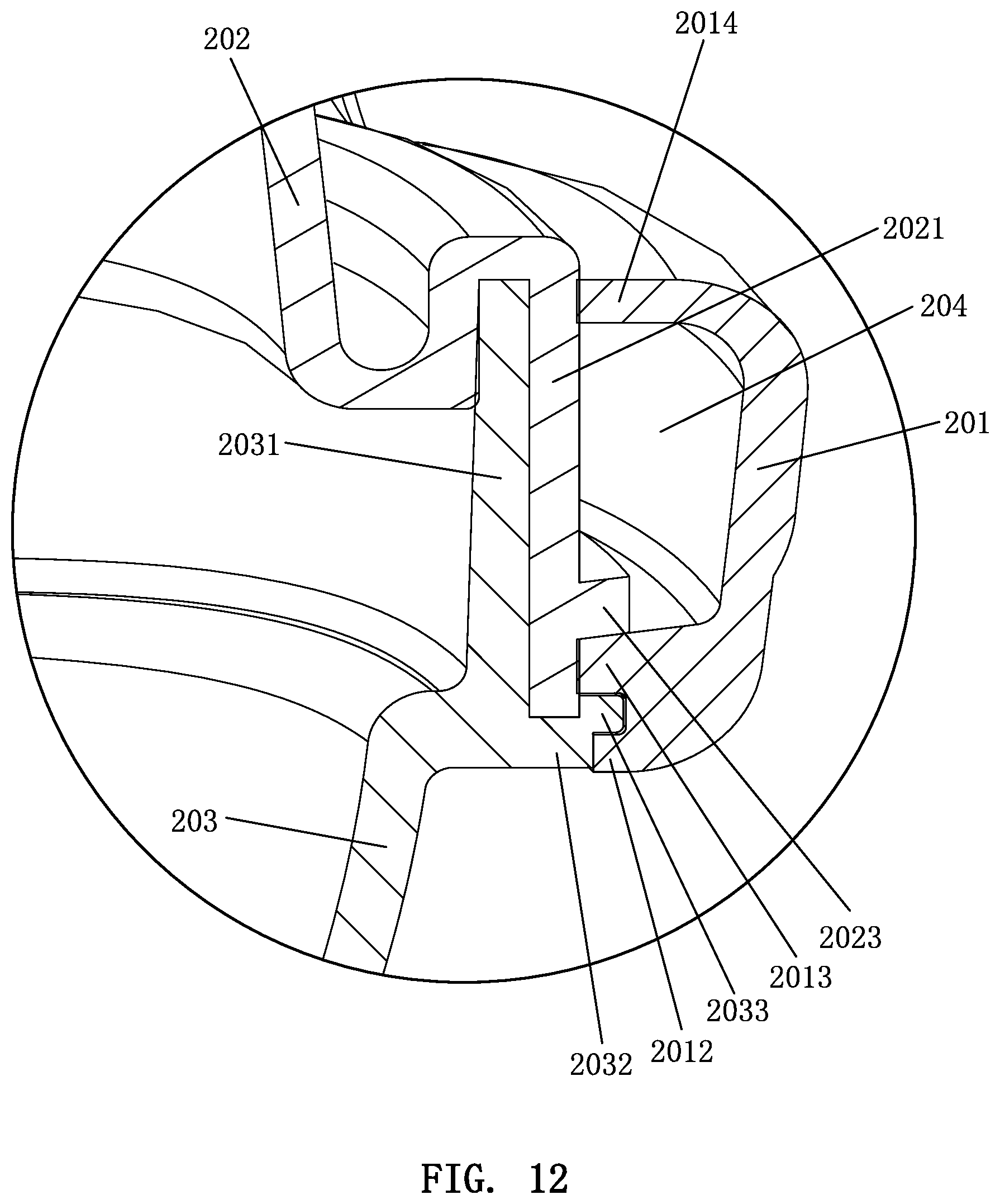
[0024] FIG. 12 is a partially schematic view of FIG. 11.
DETAILED DESCRIPTION OF THE PREFERRED EMBODIMENTS
[0025] Embodiments of the present invention will now be described, by way of example only, with reference to the accompanying drawings.
[0026] Referring to FIGS. 1 through 12, a rotatable folding diving mask according to an embodiment of the present invention comprises a mask 10, a snorkel 20, and an elastic binding strap 30. The snorkel 20 is rotatably connected to an upper end of a front side of the mask 10 in a foldable manner. The elastic binding strap 30 is detachably connected to a rear side of the mask 10. The mask 10 is provided with a first connecting portion 11 for connecting the snorkel 20. The snorkel 20 is provided with a second connecting portion 21 for connecting the mask 10. The first connecting portion 11 and the second connecting portion 21 are connected through a rotating shaft 101. One side of the first connecting portion 11 is provided with a control button 40 for controlling the snorkel 20 to be rotated and folded. One side of the second connecting portion 21 is provided with a positioning recess 22. One end of the control button 40 has a positioning buckle 422. When the snorkel 20 is in an unfolded state, the positioning buckle 422 is positioned in the positioning recess 22. When the snorkel 20 is to be folded, the control button 40 is pressed and then the positioning buckle 422 is disengaged from the positioning recess 22. At this time, the snorkel 20 can be rotated and folded into a cavity at the rear side of the mask 10 through the rotating shaft 101. The elastic binding strap 30 is provided with a connecting buckle 31 for connecting the mask 10, and correspondingly, the mask 10 is provided with a locating buckle 12 for connecting the elastic binding strap 30. The connecting buckle 31 is mated with the locating buckle 12.
[0027] The control button 40 includes a press portion 41 and a linkage portion 42. The linkage portion 42 is rotatably connected to the mask 10 through a positioning shaft 102. One side of the press portion 41 is convexly provided with a stroke protrusion 411. The linkage portion 42 is formed with a corresponding stroke groove 421. The stroke protrusion 411 is movably fitted in the stroke groove 421. The positioning buckle 422 is disposed on the linkage portion 42. When the press portion 41 is pressed toward the snorkel 20, the press portion 41 moves toward the snorkel 20 and links the stroke projection 411 to displace in the stroke groove 421, the linkage portion 42 is rotated by the press portion 41, and the positioning buckle 422 is disengaged from the positioning recess 22 by the rotation of the linkage portion 42.
[0028] The press portion 41 is provided with a limiting protrusion 412. The limiting protrusion 412 is located at one side of the stroke protrusion 411. The linkage portion 42 is provided with a first limiting slot 423 and a second limiting slot 424. The first limiting slot 423 and the second limiting slot 424 are spaced apart from each other. The first limiting slot 423 is disposed farther away from the positioning buckle 422 than the second limiting slot 424. The linkage portion 42 is provided with a stopping portion 103. When the snorkel 20 is in the unfolded state, the limiting protrusion 412 is confined in the first limiting slot 423, and the press portion 41 is limited to the outer surface of the mask 10 and cannot act on the linkage portion 42. When the snorkel 20 is to be folded, the press portion 41 is pressed, and the limiting protrusion 412 is displaced toward the snorkel 20 with the press portion 41 until the limiting protrusion 412 is confined in the second limiting slot 424. One end of the stroke protrusion 411 is limited to one side of the stopping portion 103. The press portion 41 stops displacement. The press portion 41 is disengaged from the restriction of the mask 10. The linkage portion 42 is rotated by the press portion 41. The positioning buckle 422 is disengaged from the positioning recess 22 by the rotation of the linkage portion 42. The limiting protrusion 412 is preferably a hemispherical protrusion, correspondingly, the first limiting slot 423 and the second limiting slot 424 are preferably hemispherical slots to facilitate more precise displacement of the limiting protrusion 412 and provide the user with a feeling of shift adjustment and enhance the user's experience.
[0029] The linkage portion 42 further has an elastic rotation support portion 425 for supporting the rotation of the linkage portion 42. The elastic rotation support portion 425 and the positioning buckle 422 are disposed at two ends of the linkage portion 42, respectively. The stroke groove 421 is located between the elastic rotation support portion 425 and the positioning buckle 422. The elastic rotation support portion 425 is an arc-shaped elastic portion. The arc-shaped elastic portion is curved outward from one side of the linkage portion 42. When the press portion 41 is pressed, the linkage portion 42 is rotated outwardly about the positioning shaft 102 by the elastic rotation support portion 425 as a support point by the linkage of the press portion 41. The positioning buckle 422 is disengaged from the positioning recess 22 to release the snorkel 20, so that the snorkel 20 can be folded.
[0030] Preferably, the locating buckle 12 is detachably connected to the mask 10. The locating buckle 12 has an elastic engaging block 121. The elastic engaging block 121 has an engaging block body 1211 and an elastic buckle arm 1212 connected to the engaging block body 1211. Correspondingly, the mask is formed with an engaging hole 14. One side of the engaging hole 14 communicates with a barb groove 141. The elastic engaging block 121 is detachably fitted into the engaging hole 14. The engaging block body 1211 is fitted into the engaging hole 14. The elastic buckle arm 1212 is engaged in the barb groove 141.
[0031] Furthermore, the mask 10 has a first mounting trough 13. The snorkel 20 has a second mounting trough 23. One end of the control button 40 is mounted in the first mounting trough 13, and another end of the control button 40 extends into the second mounting trough 23. The positioning recess 22 is formed in the second mounting trough 23. The stopping portion 103 is located at one side of the first mounting trough 13. The first connecting portion 11 has a first connecting hole 111. The second connecting portion 21 has a second connecting hole 211. The first connecting hole 111 and the second connecting hole 211 are connected through the rotating shaft 101. The first mounting trough 13 and the second mounting trough 23 are located at opposite sides of the first connecting hole 111 and the second connecting hole 211, respectively.
[0032] The mask 10 includes a mask frame 201, a mask pad 202, and a mask lens 203. Both the mask pad 202 and the mask lens 203 are mounted on the mask frame 201. The mask frame 201 has an air groove 2011. The mask pad 202 has a sealing wall 2021. The mask lens 203 has a first connecting wall 2031 and a second connecting wall 2032. The second connecting wall 2032 extends outward from the outer side of the first connecting wall 2031. The sealing wall 2021 is located between the mask frame 201 and the first connecting wall 2031. The inner side of the sealing wall 2021 is in close contact with the outer side of the first connecting wall 2031. One end of the sealing wall 2021 is connected to the second connecting wall 2032. One end of the second connecting wall 2032 is connected to the mask frame 201. The outer side of the sealing wall 2021 seals the air groove 2011 to form an air passage 204.
[0033] Specifically, the mask frame 201 further has a first sealing flange 2012, a second sealing flange 2013, and a third sealing flange 2014. A first connecting groove 2015 is formed between the first sealing flange 2012 and the second sealing flange 2013. The air groove 2011 is formed between the second sealing flange 2013 and the third sealing flange 2014. The second connecting wall 2032 has a fourth sealing flange 2033 and a second connecting groove 2034. The second connecting groove 2034 is recessed from one side of the fourth sealing flange 2033. The other side of the fourth sealing flange 2033 is recessed to form a third connecting groove 2035. The third connecting groove 2035 extends from the inner side of the fourth sealing flange 2033 to the outer side of the first connecting wall 2031. The inner side of the sealing wall 2021 is formed with a fourth connecting groove 2022 on the mask pad 202. One end of the first connecting wall 2031 is connected to the fourth connecting groove 2022. One end of the sealing wall 2021 is connected to the third connecting groove 2035. One end of the second connecting wall 2032 is connected to the first connecting groove 2015. The first sealing flange 2012 is connected to the second connecting groove 2034. The second sealing flange 2013 and the third sealing flange 2014 are closely attached to the outside of the sealing wall 2021.
[0034] Preferably, the outer side of the sealing wall 2021 is convexly provided with a positioning flange 2023. One side of the positioning flange 2023 abuts against the second sealing flange 2013 and extends into the air groove 2011 to ensure the sealing of the sealing wall 2021 among the first connecting wall 2031, the second connecting wall 2032, and the mask frame 201. The positioning of the sealing wall 2021 is more stable, which facilitates the connection of the mask pad 202, the mask lens 203, and the mask frame 201.
[0035] In addition, the mask 10 further has a breathing room 205. The air passage 204 communicates with the snorkel 20 and the breathing room 205. Preferably, there are two air passages 204 in this embodiment. The two air passages 204 communicate with the snorkel 20 and the breathing room 205.
[0036] Although particular embodiments of the present invention have been described in detail for purposes of illustration, various modifications and enhancements may be made without departing from the spirit and scope of the present invention. Accordingly, the present invention is not to be limited except as by the appended claims
* * * * *
D00000
D00001
D00002
D00003
D00004
D00005
D00006
D00007
D00008
D00009
D00010
D00011
D00012
XML
uspto.report is an independent third-party trademark research tool that is not affiliated, endorsed, or sponsored by the United States Patent and Trademark Office (USPTO) or any other governmental organization. The information provided by uspto.report is based on publicly available data at the time of writing and is intended for informational purposes only.
While we strive to provide accurate and up-to-date information, we do not guarantee the accuracy, completeness, reliability, or suitability of the information displayed on this site. The use of this site is at your own risk. Any reliance you place on such information is therefore strictly at your own risk.
All official trademark data, including owner information, should be verified by visiting the official USPTO website at www.uspto.gov. This site is not intended to replace professional legal advice and should not be used as a substitute for consulting with a legal professional who is knowledgeable about trademark law.