Underfloor Double Skin Structure, Vehicle Underfloor Structure, And Vehicle
TANIMOTO; Koshi ; et al.
U.S. patent application number 16/498056 was filed with the patent office on 2020-04-02 for underfloor double skin structure, vehicle underfloor structure, and vehicle. The applicant listed for this patent is Mitsubishi Heavy Industries Engineering, Ltd.. Invention is credited to Ichiro JOREN, Yoshinori KATO, Hiroyuki KONO, Koshi TANIMOTO.
| Application Number | 20200101988 16/498056 |
| Document ID | / |
| Family ID | 63677784 |
| Filed Date | 2020-04-02 |


| United States Patent Application | 20200101988 |
| Kind Code | A1 |
| TANIMOTO; Koshi ; et al. | April 2, 2020 |
UNDERFLOOR DOUBLE SKIN STRUCTURE, VEHICLE UNDERFLOOR STRUCTURE, AND VEHICLE
Abstract
An underfloor double skin structure includes a first upper plate including a pair of first thin portions disposed on both end portions thereof and a first thick portion disposed inwardly with respect to the pair of first thin portions, a first lower plate disposed to be spaced apart downward of the first upper plate and including a pair of second thin portions disposed on both end portions thereof and a second thick portion disposed inwardly with respect to the pair of second thin portions, a first rib group integrally formed with the first upper plate and the first lower plate and connects the first upper plate and the first lower plate, a reinforcing body is formed of the first thick portion, the second thick portion, and a pair of thick ribs, and the second thick portion is disposed downward of the pair of second thin portions.
| Inventors: | TANIMOTO; Koshi; (Tokyo, JP) ; JOREN; Ichiro; (Tokyo, JP) ; KONO; Hiroyuki; (Tokyo, JP) ; KATO; Yoshinori; (Tokyo, JP) | ||||||||||
| Applicant: |
|
||||||||||
|---|---|---|---|---|---|---|---|---|---|---|---|
| Family ID: | 63677784 | ||||||||||
| Appl. No.: | 16/498056 | ||||||||||
| Filed: | March 30, 2018 | ||||||||||
| PCT Filed: | March 30, 2018 | ||||||||||
| PCT NO: | PCT/JP2018/013676 | ||||||||||
| 371 Date: | September 26, 2019 |
| Current U.S. Class: | 1/1 |
| Current CPC Class: | B61F 1/12 20130101; B61D 17/10 20130101; B61F 1/00 20130101; B61D 17/041 20130101 |
| International Class: | B61F 1/12 20060101 B61F001/12; B61D 17/10 20060101 B61D017/10; B61D 17/04 20060101 B61D017/04 |
Foreign Application Data
| Date | Code | Application Number |
|---|---|---|
| Mar 31, 2017 | JP | 2017-069448 |
Claims
1. An underfloor double skin structure configuring an underfloor for a vehicle, comprising: a first upper plate that extends in a forward and rearward direction of the vehicle; a first lower plate that extends in the forward and rearward direction of the vehicle, the first lower plate being disposed to be spaced apart downward of the first upper plate; and a first rib group that includes a plurality of ribs, the plurality of ribs being integrally formed with the first upper plate and the first lower plate, the plurality of ribs being provided between the first upper plate and the first lower plate, and the plurality of ribs being configured to connect the first upper plate and the first lower plate with each other, wherein the first upper plate includes a pair of first thin portions and a first thick portion thicker than each of the pair of first thin portions, the pair of first thin portions configuring both end portions of the first upper plate in a width direction of the vehicle, the first lower plate includes a pair of second thin portions and a second thick portion thicker than each of the pair of second thin portions, the pair of second thin portions configuring the end portions of the first lower plate in the width direction of the vehicle, the first rib group includes a pair of thick ribs which are disposed to be spaced apart from each other in the width direction of the vehicle, the pair of thick ribs being configured to connect the first thick portion and the second thick portion to each other, and each of the pair of thick ribs being thicker than each of the first thin portion and the second thin portion, a reinforcing body is formed by the first thick portion, the second thick portion, and the pair of thick ribs, and the second thick portion is disposed downward of the pair of second thin portions.
2. The underfloor double skin structure according to claim 1, wherein the reinforcing body partitions a plane perpendicular to the forward and rearward direction of the vehicle to be a closed space.
3. The underfloor double skin structure according to claim 1, wherein the second thick portion and the pair of second thin portions are disposed adjacent to each other in a horizontal direction, and the second thick portion and the pair of second thin portions are integrally formed in the width direction of the vehicle.
4. The underfloor double skin structure according to claim 1, wherein the pair of thick ribs extend downward of the pair of second thin portions.
5. The underfloor double skin structure according to claim 1, wherein the pair of thick ribs connect the first thick portion and the second thick portion to each other in a vertical direction.
6. The underfloor double skin structure according to claim 5, wherein the first rib group includes a pair of inclined ribs that connect the first thick portion and the second thick portion to each other, and the pair of inclined ribs are inclined in a direction in which a distance between the pair of inclined ribs increases from the second thick portion toward the first thick portion.
7. The underfloor double skin structure according to claim 1, wherein the first thick portion and the second thick portion are flat plates, and the reinforcing body is bilaterally symmetrical with respect to a first plane which passes through a center position of the reinforcing body, the first plane being perpendicular to the first thick portion and the second thick portion, and the first plane being parallel with the forward and rearward direction of the vehicle.
8. The underfloor double skin structure according to claim 1, wherein the first thick portion and the second thick portion are flat plates, and a structure including at least the first thick portion, the second thick portion, and the pair of thick ribs in the reinforcing body is vertically symmetrical with respect to a second plane which passes through an intermediate position between the first thick portion and the second thick portion while being parallel with the first thick portion and the second thick portion.
9. The underfloor double skin structure according to claim 3, wherein the first thick portion and the pair of first thin portions are disposed adjacent to one another in the horizontal direction, and the first thick portion and the pair of first thin portions are integrally formed in the width direction of the vehicle, and a structure including the pair of first thin portions, the pair of second thin portions, the first thick portion, the second thick portion, and the pair of thick ribs are vertically symmetrical with respect to a second plane which passes through an intermediate position between the first thick portion and the second thick portion while being parallel with the first thick portion and the second thick portion.
10. A vehicle underfloor structure comprising: the underfloor double skin structure according to claim 1; and another double skin structure provided in a position adjacent to the underfloor double skin structure in the width direction of the vehicle; wherein the other double skin structure comprises: a second upper plate that extends in the forward and rearward direction of the vehicle; a second lower plate that is disposed to be spaced apart downward of the second upper plate and extends in the forward and rearward direction of the vehicle; and a second rib group that is integrally formed with the second upper plate and the second lower plate, is provided between the second upper plate and the second lower plate, and connects the second upper plate and the second lower plate to each other, wherein an end of the second upper plate is connected to an end of the first upper plate, and an end of the second lower plate is connected to an end of the first lower plate.
11. A vehicle comprising: the vehicle underfloor structure according to claim 10.
12. (canceled)
13. An underfloor double skin structure configuring an underfloor for a vehicle, comprising: a first upper plate that extends in a forward and rearward direction of the vehicle; a first lower plate that extends in the forward and rearward direction of the vehicle, the first lower plate being disposed to be spaced apart downward of the first upper plate; and a first rib group that includes a plurality of ribs, the plurality of ribs being integrally formed with the first upper plate and the first lower plate, the plurality of ribs being provided between the first upper plate and the first lower plate, and the plurality of ribs being configured to connect the first upper plate and the first lower plate with each other, wherein the first upper plate includes a pair of first thin portions and a first thick portion thicker than each of the pair of first thin portions, the pair of first thin portions configuring both end portions of the first upper plate in a width direction of the vehicle, the first lower plate includes a pair of second thin portions and a second thick portion thicker than each of the pair of second thin portions, the pair of second thin portions configuring the end portions of the first lower plate in the width direction of the vehicle, the first rib group includes a pair of thick ribs which are disposed to be spaced apart from each other in the width direction of the vehicle, the pair of thick ribs being configured to connect the first thick portion and the second thick portion to each other, and each of the pair of thick ribs being thicker than each of the first thin portion and the second thin portion, a reinforcing body is formed by the first thick portion, the second thick portion, and the pair of thick ribs, and the reinforcing body partitions a plane perpendicular to the forward and rearward direction of the vehicle to be a closed space.
14. The underfloor double skin structure according to claim 13, wherein the second thick portion and the pair of second thin portions are disposed adjacent to each other in a horizontal direction, and the second thick portion and the pair of second thin portions are integrally formed in the width direction of the vehicle.
15. The underfloor double skin structure according to claim 13, wherein the pair of thick ribs extend downward of the pair of second thin portions, and the second thick portion is disposed downward of the pair of second thin portions.
16. The underfloor double skin structure according to claim 13, wherein the pair of thick ribs connect the first thick portion and the second thick portion to each other in a vertical direction.
17. The underfloor double skin structure according to claim 16, wherein the first rib group includes a pair of inclined ribs that connect the first thick portion and the second thick portion to each other, and the pair of inclined ribs are inclined in a direction in which a distance between the pair of inclined ribs increases from the second thick portion toward the first thick portion.
18. The underfloor double skin structure according to claim 13, wherein the first thick portion and the second thick portion are flat plates, and the reinforcing body is bilaterally symmetrical with respect to a first plane which passes through a center position of the reinforcing body, the first plane being perpendicular to the first thick portion and the second thick portion, and the first plane being parallel with the forward and rearward direction of the vehicle.
19. The underfloor double skin structure according to claim 13, wherein the first thick portion and the second thick portion are flat plates, and a structure including at least the first thick portion, the second thick portion, and the pair of thick ribs in the reinforcing body is vertically symmetrical with respect to a second plane which passes through an intermediate position between the first thick portion and the second thick portion while being parallel with the first thick portion and the second thick portion.
20. The underfloor double skin structure according to claim 14, wherein the first thick portion and the pair of first thin portions are disposed adjacent to one another in the horizontal direction, and the first thick portion and the pair of first thin portions are integrally formed in the width direction of the vehicle, and a structure including the pair of first thin portions, the pair of second thin portions, the first thick portion, the second thick portion, and the pair of thick ribs are vertically symmetrical with respect to a second plane which passes through an intermediate position between the first thick portion and the second thick portion while being parallel with the first thick portion and the second thick portion.
21. A vehicle underfloor structure comprising: the underfloor double skin structure according to claim 13; and another double skin structure provided in a position adjacent to the underfloor double skin structure in the width direction of the vehicle; wherein the other double skin structure comprises: a second upper plate that extends in the forward and rearward direction of the vehicle; a second lower plate that is disposed to be spaced apart downward of the second upper plate and extends in the forward and rearward direction of the vehicle; and a second rib group that is integrally formed with the second upper plate and the second lower plate, is provided between the second upper plate and the second lower plate, and connects the second upper plate and the second lower plate to each other, wherein an end of the second upper plate is connected to an end of the first upper plate, and an end of the second lower plate is connected to an end of the first lower plate.
Description
RELATED APPLICATIONS
[0001] The present application is a National Phase of International Application Number PCT/JP2018/013676 filed Mar. 30, 2018 and claims priority to Japanese Application Number 2017-069448 filed Mar. 31, 2017.
TECHNICAL FIELD
[0002] The present invention relates to an underfloor double skin structure, a vehicle underfloor structure, and a vehicle.
[0003] Priority is claimed on Japanese Patent Application No. 2017-069448, filed on Mar. 31, 2017, the content of which is incorporated herein by reference.
BACKGROUND ART
[0004] A double skin structure being excellent in a weight reduction is applied as a vehicle body of a railway vehicle (see, for example, Patent Document 1) which is one of vehicles.
[0005] The double skin structure has an upper plate and a lower plate, and a plurality of ribs. The upper plate and the lower plate are disposed in a state of being separated from each other in an upward and downward direction of the vehicle. The plurality of ribs are disposed between the upper plate and the lower plate, and connect the upper plate and the lower plate to each other. The upper plate, the lower plate, and the plurality of ribs are thin plates. The double skin structure having such configuration is manufactured using an extrusion forming method.
[0006] In a case where a vehicle underfloor structure is formed using the double skin structure, a plurality of the double skin structures extending in a forward and rearward direction of the vehicle are disposed in a width direction of the vehicle, and the adjacent double skin structures are joined together. Specifically, for example, the upper plates are joined together, and the lower plates are joined together.
[0007] As described above, the double skin structure is formed of the thin plates. Therefore, in the double skin structure, positioning end portions (joining positions) of the adjacent double skin structures can be easily performed.
[0008] On the other hand, since the double skin structure is formed of the thin plates, a strength of the double skin structure is low. In order to improve the strength of the vehicle underfloor structure, separately preparing a middle beam extending in the forward and rearward direction of the vehicle and welding the middle beam to a lower surface side of the double skin structure of the vehicle underfloor structure are performed.
CITATION LIST
Patent Literature
[0009] [Patent Document 1] Japanese Patent No. 3625779
SUMMARY OF INVENTION
Technical Problem
[0010] However, in a case where the middle beam is welded to the vehicle underfloor structure, it is necessary to perform the welding over the entire length of the middle beam, which is extremely complicated.
[0011] An object of the present invention is to provide an underfloor double skin structure that can be easily positioned with respect to a joining position of another double skin structure and improve a strength of a vehicle underfloor structure with a simple structure, the vehicle underfloor structure, and a vehicle.
Solution to Problem
[0012] According to an aspect of the present invention, in order to solve the problem, there is provided an underfloor double skin structure of an underfloor for a vehicle. The underfloor double skin structure includes a first upper plate that extends in a forward and rearward direction of the vehicle, a first lower plate that extends in the forward and rearward direction of the vehicle, the first lower plate being disposed to be spaced apart downward of the first upper plate, and a first rib group that includes a plurality of ribs, the plurality of ribs being integrally formed with the first upper plate and the first lower plate, the plurality of ribs being provided between the first upper plate and the first lower plate, and the plurality of ribs being configured to connect the first upper plate and the first lower plate with each other, wherein the first upper plate includes a pair of first thin portions and a first thick portion thicker than each of the pair of first thin portions, the pair of first thin portions configuring both end portions of the first upper plate in a width direction of the vehicle, the first lower plate includes a pair of second thin portions and a second thick portion thicker than each of the pair of second thin portions, the pair of second thin portions configuring the end portions of the first lower plate in the width direction of the vehicle, the first rib group includes a pair of thick ribs which are disposed to be spaced apart from each other in the width direction of the vehicle, the pair of thick ribs being configured to connect the first thick portion and the second thick portion to each other, and each of the pair of thick ribs being thicker than each of the first thin portion and the second thin portion, and a reinforcing body is formed by the first thick portion, the second thick portion, and the pair of thick ribs.
[0013] According to the present invention, the underfloor double skin structure (including a reinforcing body that improves a strength of a vehicle underfloor structure) including the first upper plate, the first lower plate, and the first rib group is made into an integral structure such that there is no necessity to weld the reinforcing body to a lower surface side of the first lower plate as a separate body from the first lower plate. Therefore, it is possible to improve a strength of the vehicle underfloor structure with a simple structure.
[0014] The both end portions of the first upper plate and the first lower plate which are connected to another double skin structure in the width direction of the vehicle are formed by the first thin portions and the second thin portions such that it is possible to easily deform the both end portions of the first upper plate and the first lower plate in the width direction of the vehicle, compared to the first thick portion and the second thick portion.
[0015] Therefore, when the other double skin structure is joined to the both end portions of the underfloor double skin structure in the width direction of the vehicle, it is possible to easily position ends of the underfloor double skin structure with respect to ends of the other double skin structure.
[0016] In the underfloor double skin structure according to the aspect of the present invention, the reinforcing body may partition a plane perpendicular to the forward and rearward direction of the vehicle to be a closed space.
[0017] In such configuration, since a groove or an opening does not exist in a portion that partitions a space in the reinforcing body, it is possible to suppress a decrease in strength of the reinforcing body.
[0018] In the underfloor double skin structure according to the aspect of the present invention, the second thick portion and the pair of second thin portions may be disposed adjacent to one another in a horizontal direction, and the second thick portion and the pair of second thin portions may be integrally formed in the width direction of the vehicle.
[0019] In such configuration, when the underfloor double skin structure is manufactured using an extrusion forming method, a warpage is less likely to occur in the underfloor double skin structure during extrusion forming (during manufacturing). Therefore, it is possible to easily manufacture the underfloor double skin structure using the extrusion forming method.
[0020] In the underfloor double skin structure according to the aspect of the present invention, the pair of thick ribs may extend downward of the pair of second thin portions, and the second thick portion may be disposed downward of the pair of second thin portions.
[0021] According to such configuration, it is possible to match a height of a lower surface of the double skin structure to a height of a lower surface of the middle beam fixed to the lower surface side of the double skin structure of the related art.
[0022] Therefore, it is possible to apply the underfloor double skin structure to the vehicle underfloor structure without changing specifications (for example, thickness, length, or the like) of a member to be directly or indirectly connected to the second thick portion.
[0023] In the underfloor double skin structure according to the aspect of the present invention, the pair of thick ribs may connect the first thick portion and the second thick portion to each other in a vertical direction.
[0024] The pair of thick ribs that connect the first thick portion and the second thick portion to each other in the vertical direction is included such that it is possible to enhance the strength of the reinforcing body against a load in an upward and downward direction.
[0025] In the underfloor double skin structure according to the aspect of the present invention, the first rib group may include a pair of inclined ribs that connect the first thick portion and the second thick portion to each other, and the pair of inclined ribs may be inclined in a direction in which a distance between the pair of inclined ribs increases from the second thick portion toward the first thick portion.
[0026] According to such configuration, it is possible to release a load that the second thick portion receives from a lower side thereof in an oblique direction. Therefore, it is possible to disperse the load that the second thick portion receives from the lower side thereof.
[0027] In the underfloor double skin structure according to the aspect of the present invention, the first thick portion and the second thick portion may be flat plates, and the reinforcing body may be bilaterally symmetrical with respect to a first plane which passes through a center position of the reinforcing body, is perpendicular to the first thick portion and the second thick portion, and is parallel with the forward and rearward direction of the vehicle.
[0028] According to such configuration, since a left half structure and a right half structure of the reinforcing body have the same structure, it is possible to decrease a difference in strength between the left half structure and the right half structure of the reinforcing body.
[0029] In the underfloor double skin structure according to the aspect of the present invention, the first thick portion and the second thick portion may be flat plates, and a structure including at least the first thick portion, the second thick portion, and the pair of thick ribs in the reinforcing body may be vertically symmetrical with respect to a second plane which passes through an intermediate position between the first thick portion and the second thick portion, and is parallel with the first thick portion and the second thick portion.
[0030] According to such configuration, it is possible to decrease a difference in strength between upper and lower portions of the reinforcing body.
[0031] In the underfloor double skin structure according to the aspect of the present invention, the first thick portion and the pair of first thin portions may be disposed adjacent to one another in the horizontal direction, and the first thick portion and the pair of first thin portions are integrally formed in the width direction of the vehicle, and a structure including the pair of first thin portions, the pair of second thin portions, the first thick portion, the second thick portion, and the pair of thick ribs may be vertically symmetrical with respect to a second plane which passes through an intermediate position between the first thick portion and the second thick portion, and is parallel with the first thick portion and the second thick portion.
[0032] According to such configuration, when the underfloor double skin structure is manufactured using the extrusion forming method, warpage due to a thermal shrinkage during extrusion forming is less likely to occur in the underfloor double skin structure during manufacturing. Therefore, it is possible to form the structure including the pair of first thin portions, the pair of second thin portions, and the reinforcing body with high accuracy using the extrusion forming method.
[0033] According to another aspect of the present invention, in order to solve the problem, there is provided a vehicle underfloor structure including the underfloor double skin structure, and another double skin structure provided in a position adjacent to the underfloor double skin structure in the width direction of the vehicle, wherein the other double skin structure includes a second upper plate that extends in the forward and rearward direction of the vehicle, a second lower plate that is disposed to be spaced apart downward of the second upper plate and extends in the forward and rearward direction of the vehicle, and a second rib group that is integrally formed with the second upper plate and the second lower plate, is provided between the second upper plate and the second lower plate, and connects the second upper plate and the second lower plate to each other, in which an end of the second upper plate is connected to an end of the first upper plate, and an end of the second lower plate is connected to an end of the first lower plate.
[0034] According to such configuration, it is possible to dispose the underfloor double skin structure in a portion where reinforcement is required and dispose the other double skin structure that does not have the reinforcing body in a portion where reinforcement is not required in the vehicle underfloor structure, and join together (for example, friction stir joining) the underfloor double skin structure and the other double skin structure.
[0035] Therefore, since it is not necessary to weld the reinforcing body to the double skin structure, it is possible to improve the strength of the vehicle underfloor structure of the vehicle with a simple structure.
[0036] According to still another aspect of the present invention, in order to solve the problem, there is provided a vehicle including the vehicle underfloor structure.
[0037] According to such configuration, it is possible to enhance the strength of the vehicle underfloor structure against the load received from a lower side thereof.
[0038] The vehicle according to the aspect of the present invention may further include a bolster spring provided downward of a second thick portion of the underfloor double skin structure.
[0039] According to such configuration, it is possible to enhance the strength of the vehicle underfloor structure against the load received from the lower side of the vehicle underfloor structure.
Advantageous Effects of Invention
[0040] According to the present invention, it is possible to easily position the end of the underfloor double skin structure with respect to the end of another double skin structure and improve the strength of the vehicle underfloor structure with a simple structure.
BRIEF DESCRIPTION OF DRAWINGS
[0041] FIG. 1 is a front view showing a schematic configuration of a vehicle according to a first embodiment of the present invention.
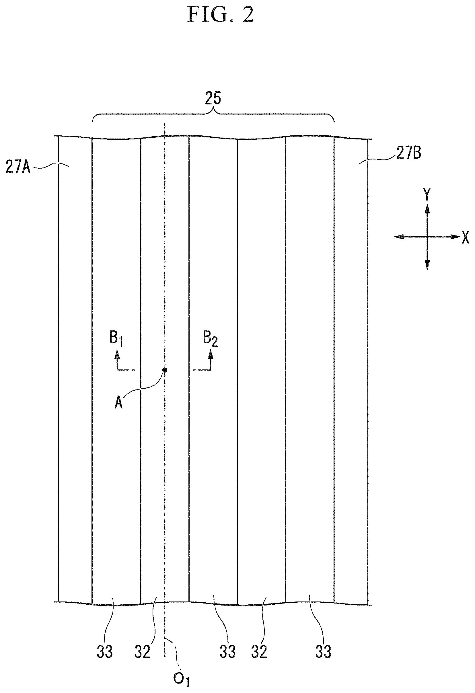
[0042] FIG. 2 is a plan view of a vehicle underfloor structure and a pair of side beams shown in FIG. 1.
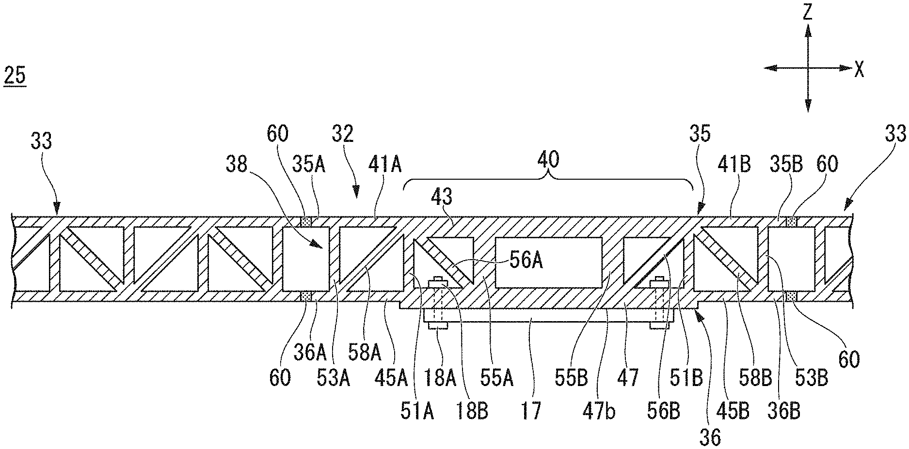
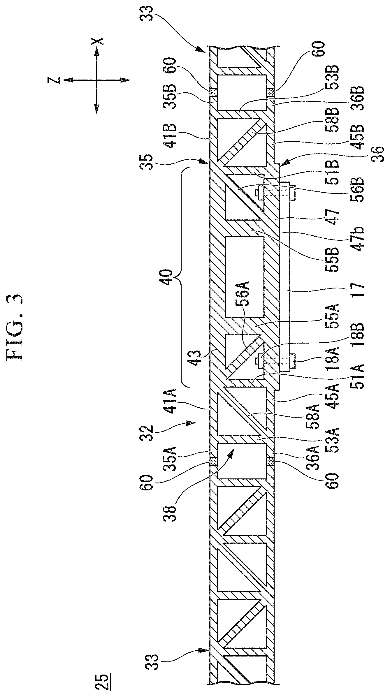
[0043] FIG. 3 is a sectional view of the vehicle underfloor structure shown in FIG. 2 in a direction of line B.sub.1-B.sub.2.
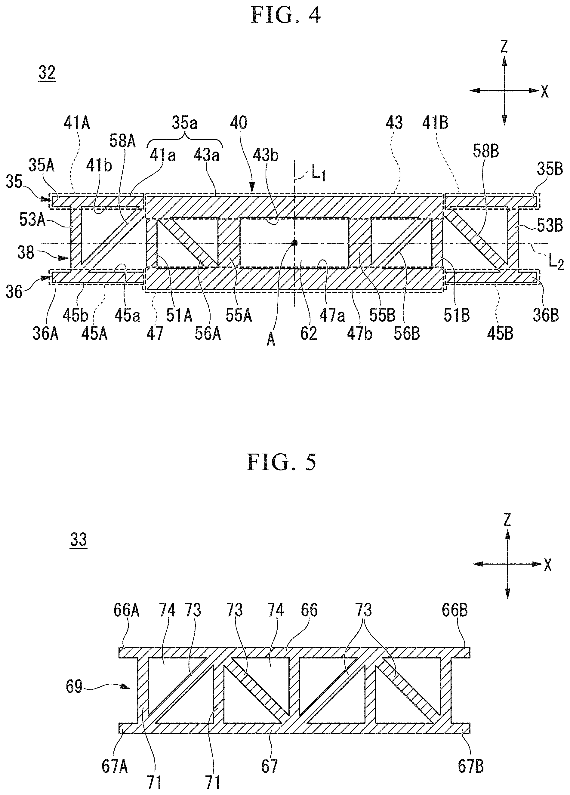
[0044] FIG. 4 is an enlarged sectional view of an underfloor double skin structure shown in FIG. 3.
[0045] FIG. 5 is an enlarged sectional view of the double skin structure shown in FIG. 3.
[0046] FIG. 6 is a sectional view showing a schematic configuration of an underfloor double skin structure according to a modification example of the first embodiment of the present invention.
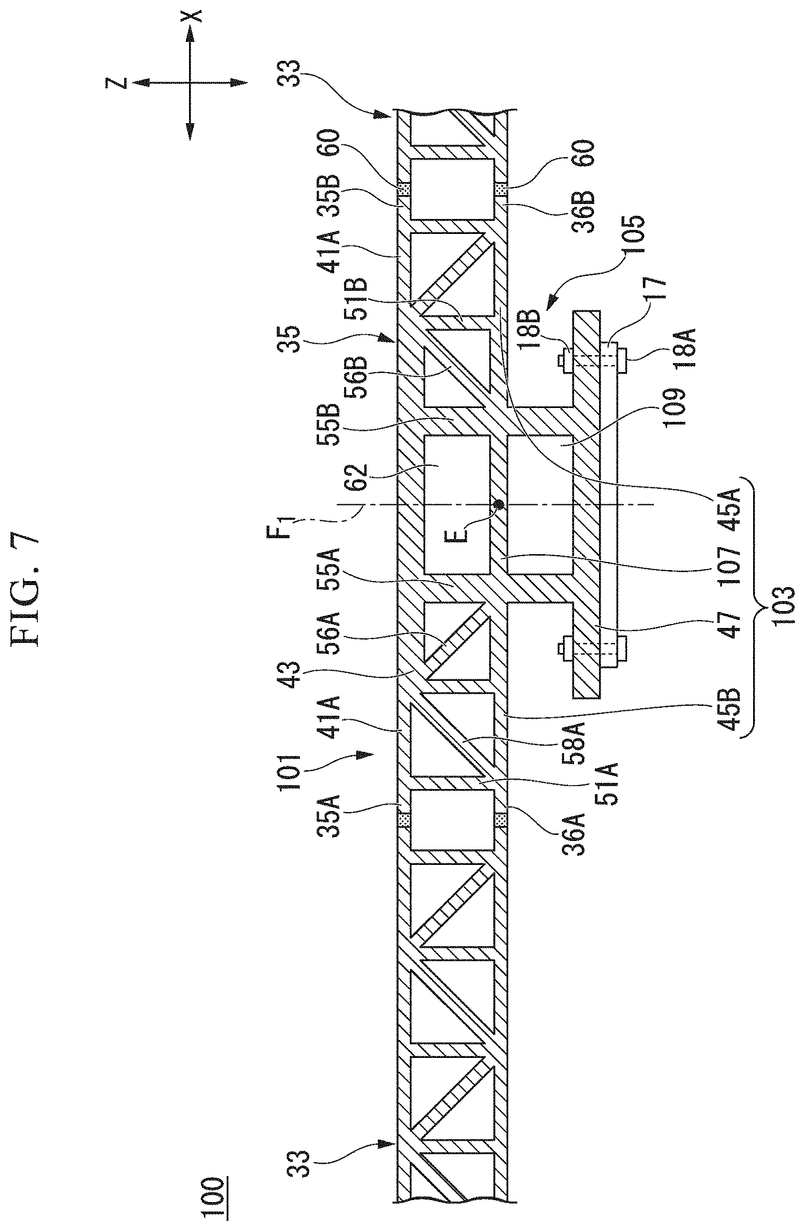
[0047] FIG. 7 is a sectional view showing a part of a vehicle underfloor structure according to a second embodiment of the present invention.
DESCRIPTION OF EMBODIMENTS
[0048] Hereinafter, embodiments to which the present invention is applied will be described in detail with reference to the drawings.
First Embodiment
[0049] A vehicle 10 of a first embodiment will be described with reference to FIGS. 1 to 5. In FIG. 1, a track type vehicle is shown as an example of the vehicle 10. In FIGS. 1 and 3 to 5, an X direction denotes a width direction of the vehicle 10, and a Z direction denotes an upward and downward direction and a height direction (that is also a vertical direction) of the vehicle 10. In FIG. 2, a Y direction denotes a forward and rearward direction of the vehicle 10 which is perpendicular to the X direction and the Z direction, and O.sub.1 denotes a center line O.sub.1 of an underfloor double skin structure 32 which passes through a center position A. The center position A is also an intermediate position between a first thick portion 43 and a second thick portion 47.
[0050] In FIG. 4, A denotes a center position of a reinforcing body 40 (hereinafter, referred to as "center position A"), and L.sub.1 denotes a first plane which passes through the center position A, is perpendicular to the first thick portion 43 and the second thick portion 47, and is parallel with the Y direction (hereinafter, referred to as "first plane L.sub.1"). In FIGS. 1 to 5, the same reference signs will be assigned to the same configuration elements as those of the structure shown in FIGS. 1 to 5.
[0051] In the first embodiment, the track type vehicle which is guided by a side guide-type guide rail 3 provided on both sides of a track 2 in a width direction and travels on a traveling path 4 of the track 2 will be described as an example of the vehicle 10.
[0052] The vehicle 10 includes a vehicle body 15, a plate 17, a bolt 18A, a nut 18B, and a traveling device 22.
[0053] The vehicle body 15 includes a vehicle underfloor structure 25 of an underfloor for the vehicle body, a pair of side beams 27A and 27B, a pair of side walls 29A and 29B, and a ceiling (not shown).
[0054] The vehicle underfloor structure 25 is provided between the pair of side beams 27A and 27B disposed in a state of being separated from each other in the X direction. The vehicle underfloor structure 25 includes two underfloor double skin structures 32 extending in the Y direction and three double skin structures 33 (another double skin structure) extending in the Y direction.
[0055] The vehicle underfloor structure 25 is configured such that the double skin structures 33 and the underfloor double skin structures 32 are alternately disposed in the X direction.
[0056] Each of the number of the underfloor double skin structures 32 and the number of the double skin structures 33 shown in FIGS. 1 and 2 is merely an example, and is not limited to these numbers.
[0057] The underfloor double skin structure 32 includes a first upper plate 35, a first lower plate 36, a first rib group 38, and the reinforcing body 40. The underfloor double skin structure 32 is manufactured, for example, by extrusion forming a lightweight alloy such as an aluminum alloy.
[0058] The first upper plate 35 extends in the Y direction. The first upper plate 35 includes a pair of first thin portions 41A and 41B and the first thick portion 43 of the reinforcing body 40.
[0059] The pair of first thin portions 41A and 41B extend in the Y direction, and forms both end portions of the first upper plate 35 in the X direction. The first thin portion 41A includes an end 35A disposed in the X direction. The first thin portion 41B includes an end 35B disposed in the X direction.
[0060] Each of a pair of the ends 35A and 35B (both ends) is connected to the double skin structure 33 disposed on each of both sides of the underfloor double skin structure 32 through a joining portion 60.
[0061] As the joining portion 60, for example, a friction stir joining portion to be formed at the time of friction stir joining can be used. In this case, the joining portions 60 are formed by melting and then solidifying a material forming a part of the ends 35A and 35B of the first upper plate 35 and a material forming an end of the double skin structure 33.
[0062] The first thick portion 43 extends in the Y direction, and is provided between the first thin portion 41A and the first thin portion 41B. The first thick portion 43 and the pair of first thin portions 41A and 41B are disposed adjacent to one another in the horizontal direction. The first thick portion 43 is integrally formed with the pair of first thin portions 41A and 41B in the X direction. That is, the first thick portion 43 and the pair of first thin portions 41A and 41B are integrally formed with one another.
[0063] The first thick portion 43 is a portion thicker than each of the pair of first thin portions 41A and 41B. An upper surface 43a of the first thick portion 43 is disposed at the same height as that of an upper surface 41a of each of the pair of first thin portions 41A and 41B in the Z direction. That is, an upper surface 35a of the first upper plate 35 which is formed of the upper surface 41a of each of the pair of first thin portions 41A and 41B and the upper surface 43a of the first thick portion 43 is flat.
[0064] Therefore, the first thick portion 43 protrudes downward of a lower surface 41b of the pair of first thin portions 41A and 41B. The thickness of the first thick portion 43 can be set to, for example, 2 to 4 times the thickness of each of the pair of first thin portions 41A and 41B. As the first thick portion 43, for example, a flat plate can be used.
[0065] The first lower plate 36 is disposed downward of the first upper plate 35 in a state of being separated from the first upper plate 35. The first lower plate 36 extends in the Y direction.
[0066] The first lower plate 36 includes a pair of second thin portions 45A and 45B and a second thick portion 47 of the reinforcing body 40.
[0067] The pair of second thin portions 45A and 45B extends in the Y direction, and forms both end portions of the first lower plate 36 in the X direction. An upper surface 45a of each of the second thin portions 45A and 45B faces the lower surface 41b of each of the first thin portions 41A and 41B in the Z direction.
[0068] The second thin portion 45A includes an end 36A disposed in the X direction. The second thin portion 45B includes an end 36B disposed in the X direction.
[0069] Each of a pair of the ends 36A and 36B is connected to the double skin structure 33 disposed on each of the both sides of the underfloor double skin structure 32 through the joining portion 60.
[0070] A thickness of each of the pair of second thin portions 45A and 45B can be, for example, the same as the thickness of each of the pair of first thin portions 41A and 41B.
[0071] The second thick portion 47 is provided between the second thin portion 45A and the second thin portion 45B. The thickness of the second thick portion 47 is thicker than the thickness of each of the pair of second thin portions 45A and 45B.
[0072] The second thick portion 47 and the pair of second thin portions 45A and 45B are disposed adjacent to one another in the horizontal direction. The second thick portion 47 is integrally formed with the pair of second thin portions 45A and 45B in the X direction. That is, the second thick portion 47 and the pair of second thin portions 45A and 45B are integrally formed with one another.
[0073] As such, the second thick portion 47 and the pair of second thin portions 45A and 45B are integrally formed with one another in the X direction, whereby it is possible to decrease a difference between a position of the second thick portion 47 and a position of each of the pair of second thin portions in the Z direction.
[0074] Therefore, when the underfloor double skin structure 32 is manufactured using the extrusion forming method, the warpage is less likely to occur in the underfloor double skin structure 32 during extrusion forming (during manufacturing). Thus, the underfloor double skin structure 32 can be easily manufactured.
[0075] The second thick portion 47 faces the first thick portion 43 in a state of being separated downward of the first thick portion 43. Therefore, an upper surface 47a of the second thick portion 47 faces a lower surface 43b of the first thick portion 43.
[0076] The width of the second thick portion 47 in the X direction can be, for example, the same size as a width of the first thick portion 43 in the X direction. In addition, the thickness of the second thick portion 47 can be, for example, the same as the thickness of the first thick portion 43. As the second thick portion 47, for example, a flat plate can be used.
[0077] The first rib group 38 is integrally formed with the first upper plate 35 and the first lower plate 36. That is, the first rib group 38 is integrally formed with the first upper plate 35 and the first lower plate 36.
[0078] The first rib group 38 includes a pair of first vertical ribs 51A and 51B, a pair of thick ribs 55A and 55B, and a pair of first inclined ribs 56A and 56B of the reinforcing body 40, a pair of second vertical ribs 53A and 53B, and a pair of second inclined ribs 58A and 58B.
[0079] The pair of first vertical ribs 51A and 51B are disposed between the first thick portion 43 and the second thick portion 47 in a state of being separated from each other in the X direction. The pair of first vertical ribs 51A and 51B extend in the Y direction. The pair of first vertical ribs 51A and 51B are perpendicular to the first thick portion 43 and the second thick portion 47.
[0080] The first vertical rib 51A connects one end of the first thick portion 43 and one end of the second thick portion 47 to each other in the Z direction. The first vertical rib 51B connects the other end of the first thick portion 43 and the other end of the second thick portion 47 to each other in the Z direction.
[0081] The thickness of each of the pair of first vertical ribs 51A and 51B is thinner than the thickness of each of the first thick portion 43 and the second thick portion 47. The thickness of each of the pair of first vertical ribs 51A and 51B can be, for example, the same as that of each of the first thin portions 41A and 41B and the second thin portions 45A and 45B.
[0082] The second vertical rib 53A is provided between the first thin portion 41A of one end portion of the first upper plate and the second thin portion 45A of one end portion of the first lower plate. The second vertical rib 53A extends in the Y direction.
[0083] The second vertical rib 53A is perpendicular to the first thin portion 41A and the second thin portion 45A. The second vertical rib 53A connects one end portion of the first thin portion 41A and one end portion of the second thin portion 45A to each other in the Z direction.
[0084] The second vertical rib 53B is provided between the first thin portion 41B of the other end portion of the upper plate and the second thin portion 45B of the other end portion of the lower plate. The second vertical rib 53B extends in the Y direction.
[0085] The second vertical rib 53B is perpendicular to the first thin portion 41B and the second thin portion 45B. The second vertical rib 53B connects the other end portion of the first thin portion 41B and the other end portion of the second thin portion 45B to each other in the Z direction (upward and downward direction).
[0086] The thickness of each of the pair of second vertical ribs 53A and 53B is thinner than the thickness of each of the first thick portion 43 and the second thick portion 47. The thickness of each of the pair of second vertical ribs 53A and 53B can be, for example, the same as that of each of the first thin portions 41A and 41B and the second thin portions 45A and 45B.
[0087] The pair of thick ribs 55A and 55B are disposed between the first thick portion 43 and the second thick portion 47 in a state of being separated from each other in the X direction. The pair of thick ribs 55A and 55B are disposed between the first vertical rib 51A and the first vertical rib 51B.
[0088] The pair of thick ribs 55A and 55B extend in the Y direction. The pair of thick ribs 55A and 55B are perpendicular to the first thick portion 43 and the second thick portion 47. The pair of thick ribs 55A and 55B connect the first thick portion 43 and the second thick portion 47 to each other in the Z direction.
[0089] The thickness of each of the pair of thick ribs 55A and 55B is thicker than the thickness of each of the first thin portions 41A and 41B, the second thin portions 45A and 45B, the pair of first vertical ribs 51A and 51B, the pair of second vertical ribs 53A and 53B, the pair of first inclined ribs 56A and 56B, and the pair of second inclined ribs 58A and 58B.
[0090] The thickness of each of the pair of thick ribs 55A and 55B can be, for example, the same as the thickness of each of the first thick portion 43 and the second thick portion 47.
[0091] As such, the first thick portion 43 and the second thick portion 47 are connected to each other in the Z direction by the pair of thick ribs 55A and 55B, whereby it is possible to enhance a strength of the vehicle 10 against a load in the Z direction. Therefore, it is possible to enhance a strength of the reinforcing body 40 including the pair of thick ribs 55A and 55B.
[0092] The first inclined rib 56A is provided between the first vertical rib 51A and the thick rib 55A. The first inclined rib 56A extends in the Y direction.
[0093] The first inclined rib 56A is inclined in a direction from a connection position between the second thick portion 47 and the thick rib 55A toward a connection position between the first thick portion 43 and the first vertical rib 51A. The first inclined rib 56A is inclined with respect to the first thick portion 43 and the second thick portion 47. The first inclined rib 56A connects the first thick portion 43 and the second thick portion 47 to each other in an oblique direction.
[0094] The first inclined rib 56B is provided between the first vertical rib 51B and the thick rib 55B. The first inclined rib 56B extends in the Y direction.
[0095] The first inclined rib 56B is inclined in a direction (a direction opposite to an inclination direction of the first inclined rib 56A) from a connection position between the second thick portion 47 and the thick rib 55B toward a connection position between the first thick portion 43 and the first vertical rib 51B. The first inclined rib 56B is inclined with respect to the first thick portion 43 and the second thick portion 47. The first inclined rib 56B connects the first thick portion 43 and the second thick portion 47 to each other in the oblique direction.
[0096] The first inclined ribs 56A and 56B having such configuration are inclined in a direction in which a distance between the first inclined rib 56A and the first inclined rib 56B increases from the second thick portion 47 toward the first thick portion 43.
[0097] As such, the first inclined ribs 56A and 56B that connect the first thick portion 43 and the second thick portion 47 to each other and are inclined in a direction in which a distance increases from the second thick portion 47 toward the first thick portion 43 are included, whereby it is possible to release a load that the second thick portion 47 receives from a lower side thereof in the oblique direction (the inclination direction of the first inclined ribs 56A and 56B). Therefore, it is possible to disperse the load that the second thick portion 47 receives from the lower side thereof.
[0098] The second inclined rib 58A extends in the Y direction, and is provided between the first vertical rib 51A and the second vertical rib 53A. The second inclined rib 58A connects the first thin portion 41A and the second thin portion 45A to each other in a state of being inclined in a direction opposite to the first inclined rib 56A provided at an adjacent position.
[0099] The second inclined rib 58B extends in the Y direction, and is provided between the first vertical rib 51B and the second vertical rib 53B. The second inclined rib 58B connects the other first thin portion 41B and the other second thin portion 45B to each other in a state of being inclined in a direction opposite to the first inclined rib 56B provided at the adjacent position.
[0100] Shapes and the numbers of the first vertical ribs 51A and 51B, the second vertical ribs 53A and 53B, the first inclined ribs 56A and 56B, and the second inclined ribs 58A and 58B shown in FIG. 4 are merely examples, and are not limited to the shapes and numbers shown in FIG. 4.
[0101] The reinforcing body 40 includes the first thick portion 43, the second thick portion 47, the pair of first vertical ribs 51A and 51B, the pair of thick ribs 55A and 55B, and the pair of first inclined ribs 56A and 56B which are described above, and a space 62.
[0102] The space 62 is partitioned in the X direction and the Z direction by the first thick portion 43, the second thick portion 47, and the thick ribs 55A and 55B. The space 62 extends in the Y direction. The reinforcing body 40 partitions a plane (virtual plane) perpendicular to the Y direction to be a closed space. The reinforcing body 40 is disposed to surround the virtual plane.
[0103] The "closed space" in the present invention means a space in which the space 62 does not communicate with another space (space formed outside the space 62) disposed in the X direction and the Z direction in a state where the underfloor double skin structure 32 and other parts are assembled and the underfloor double skin structure 32 becomes a part of the vehicle 10.
[0104] As such, the space 62 partitioned by the first thick portion 43, the second thick portion 47, and the pair of thick ribs 55A and 55B is made into a closed space in a plane direction perpendicular to the Y direction. In such configuration, since a groove or an opening does not exist in a portion that partitions the space 62 in the first thick portion 43, the second thick portion 47, and the thick ribs 55A and 55B, it is possible to suppress a decrease in strength of the reinforcing body 40.
[0105] It is preferable that the reinforcing body 40 is formed to be bilaterally symmetrical with respect to the first plane L.sub.1 which passes through the center position A of the reinforcing body 40 and is perpendicular to the first thick portion 43 and the second thick portion 47.
[0106] As such, the reinforcing body is formed to be bilaterally symmetrical with respect to the first plane L.sub.1 which passes through the center position A of the reinforcing body 40 and is perpendicular to the first thick portion 43 and the second thick portion 47. By such configuration, since a left half structure and a right half structure of the reinforcing body 40 have the same structure, it is possible to decrease a difference in strength between the left half structure and the right half structure of the reinforcing body 40.
[0107] In addition, it is preferable that a structure including the first thick portion 43, the second thick portion 47, and the pair of thick ribs 55A and 55B in the reinforcing body 40 is formed to be vertically symmetrical with respect to a second plane L.sub.2 which passes through the intermediate position, including the center position A of the reinforcing body 40, between the first thick portion 43 and the second thick portion 47 and is parallel with the first thick portion 43 and the second thick portion 47.
[0108] As such, the structure including at least the first thick portion 43, the second thick portion 47, and the pair of thick ribs 55A and 55B in the reinforcing body 40 is formed to be vertically symmetrical with respect to the second plane L.sub.2 which passes through the center position A of the reinforcing body 40 and is parallel with the first thick portion 43 and the second thick portion 47, whereby it is possible to decrease a difference in strength between upper and lower portions of the reinforcing body 40.
[0109] According to the underfloor double skin structure 32 of the first embodiment, the underfloor double skin structure 32 (including the reinforcing body 40) including the first upper plate 35, the first lower plate 36, and the first rib group 38 is integrally formed, whereby it is not necessary to weld the reinforcing body for improving a strength of the vehicle underfloor structure to a lower surface side of the first lower plate, as a separate body from the first lower plate. Therefore, it is possible to improve the strength of the vehicle underfloor structure 25 with a simple structure.
[0110] The both end portions of the first upper plate 35 and the first lower plate 36 to be connected to the double skin structure 33 in the X direction are formed of the first thin portions 41A and 41B and the second thin portions 45A and 45B, whereby it is possible to displace the positions of the ends 35A, 35B, 36A, and 36B of the first upper plate 35 and the first lower plate 36 in the X direction.
[0111] Therefore, when the double skin structure 33 is connected to the ends 35A, 35B, 36A, and 36B of the underfloor double skin structure 32 in the X direction, it is possible to easily position the ends 35A, 35B, 36A, and 36B of the underfloor double skin structure 32 and ends 66A, 66B, 67A, and 67B of the double skin structure 33.
[0112] The double skin structure 33 includes a second upper plate 66, a second lower plate 67, and a second rib group 69.
[0113] The second upper plate 66 extends in the Y direction. The second upper plate 66 is a plate having a uniform thickness. Each of the ends 66A and 66B (both ends) of the second upper plate 66 in the X direction is connected to any one of the side beam 27A, the side beam 27B, the end 35A, and the end 35B through the joining portion 60. The thickness of the second upper plate 66 can be, for example, the same as that of each of the first thin portions 41A and 41B.
[0114] The second lower plate 67 is disposed to be spaced apart downward of the second upper plate 66 so as to face the second upper plate 66. The second lower plate 67 extends in the Y direction. The second lower plate 67 is a plate having a uniform thickness.
[0115] Each of the ends 67A and 67B (both ends) of the second lower plate 67 in the X direction is connected to any one of the side beam 27A, the side beam 27B, the end 36A, and the end 36B through the joining portion 60. The thickness of the second lower plate 67 can be, for example, the same as that of the second thick portion 47.
[0116] The second rib group 69 includes a plurality of third vertical ribs 71 and a plurality of third inclined ribs 73.
[0117] The plurality of third vertical ribs 71 are provided between the second upper plate 66 and the second lower plate 67. The plurality of third vertical ribs 71 are disposed in the X direction at predetermined intervals.
[0118] The plurality of third vertical ribs 71 extend in the Y direction, and are perpendicular to the second upper plate 66 and the second lower plate 67. The plurality of third vertical ribs 71 connect the second upper plate 66 and the second lower plate 67 to each other. A space 74 partitioned in the Z direction by the second upper plate 66 and the second lower plate 67 and extending in the Y direction is formed between two adjacent third vertical ribs 71.
[0119] A thickness of the third vertical rib 71 can be, for example, the same as that of each of the first thin portions 41A and 41B and the second thin portions 45A and 45B.
[0120] The plurality of third inclined ribs 73 are provided in each space 74. The plurality of third inclined ribs 73 connect the second upper plate 66 and the second lower plate 67 to each other in a state of being inclined with respect to the second upper plate 66 and the second lower plate 67. Two adjacent third inclined ribs 73 are inclined in different directions. A thickness of each of the plurality of third inclined ribs 73 can be, for example, the same as that of each of the first thin portions 41A and 41B and the second thin portions 45A and 45B.
[0121] According to the vehicle underfloor structure 25 of the first embodiment, the underfloor double skin structure 32 is disposed in a portion where reinforcement is required and the double skin structure 33 that does not have the reinforcing body 40 is disposed in a portion where reinforcement is not required in the vehicle underfloor structure 25, and the underfloor double skin structure 32 and the double skin structure 33 are joined together (for example, friction stir joining), whereby it is possible to form the vehicle underfloor structure 25.
[0122] Therefore, since it is not necessary to weld the reinforcing body to the double skin structure, it is possible to improve the strength of the vehicle underfloor structure 25 of the vehicle 10 with a simple structure.
[0123] The side beam 27A is joined to the double skin structure 33 of one end portion of the vehicle underfloor structure 25 in the X direction. The side beam 27B is joined to the double skin structure 33 of the other end portion of the vehicle underfloor structure 25 in the X direction.
[0124] The side beams 27A and 27B are disposed so as to interpose the vehicle underfloor structure 25 therebetween in the X direction. As the side beams 27A and 27B, for example, the double skin structure can be used.
[0125] The side wall 29A is provided on the side beam 27A. The side wall 29A extends in the Z direction and the Y direction. A lower end of the side wall 29A is connected to the side beam 27A through a joining portion (not shown).
[0126] A side wall 29B is provided on the side beam 27B. The side wall 29B extends in the Z direction and the Y direction. A lower end of the side wall 29B is connected to the side beam 27B through a joining portion (not shown). As the side walls 29A and 29B, for example, the double skin structure can be used.
[0127] The ceiling (not shown) connects an upper end of the side wall 29A and an upper end of the side wall 29B to each other. The ceiling extends in the Y direction. As the ceiling, for example, the double skin structure can be used.
[0128] The plate 17 is provided on a lower surface 47b of the second thick portion 47. The plate 17 is fixed to the second thick portion 47 by a bolt 18A penetrating the plate 17 and the second thick portion 47, and a nut 18B provided on a shaft part of the bolt 18A.
[0129] The traveling device 22 is a device that supports the vehicle body 15 to be travelable from a lower side thereof. The traveling device 22 is provided in each of front and rear parts of the vehicle body 15.
[0130] The traveling device 22 includes an air spring 76 which is a bolster spring, a damper 78, a motor (not shown), a drive shaft (not shown), a gear box 81, an axle 83, and a pair of traveling wheels 84, a suspension device (not shown), and a guide mechanism 86.
[0131] The air spring 76 is disposed between the plate 17 and a bogie frame 88. The air spring 76 is fixed to a lower surface side of the plate 17. Therefore, the air spring 76 is provided on the lower surface 47b of the second thick portion 47 through the plate 17.
[0132] As such, the air spring 76 is provided on the plate 17 fixed to the lower surface 47b of the second thick portion 47 of the vehicle underfloor structure 25, whereby it is possible to enhance the strength of the vehicle underfloor structure 25 against the load received from a lower side of the vehicle underfloor structure 25 through the plate 17.
[0133] As the air spring 76, for example, a bag-like member made of an elastic body (for example, rubber) capable of storing compressed air therein can be used. As an example of the bolster spring, the air spring 76 is described, but a bolster spring other than the air spring 76 may be used.
[0134] The damper 78 is provided to connect the plate 17 and the bogie frame 88 to each other.
[0135] The motor (not shown) generates rotational power using power to be supplied from an outside. The drive shaft is connected to a driving shaft of the motor. The motor is connected to the gear box 81 through the drive shaft.
[0136] A motor includes a casing (not shown) that covers an outside thereof. The casing is attached to the lower surface of the vehicle underfloor structure 25 through a vibration isolating material (not shown) such as a vibration isolating rubber.
[0137] The gear box 81 accommodates a power transmission mechanism such as a differential mechanism and a speed reduction mechanism. The rotational power to be transmitted from the motor to the gear box 81 is distributed to an axle shaft (not shown). The axle shaft extends from the gear box 81 to both sides in the X direction and is linked to each of the traveling wheels 84.
[0138] The axle 83 extends to the both sides in the X direction, and a base thereof is connected to the gear box 81. The axle 83 is rotatably supported by a pair of the bogie frames 88 disposed to be separated from each other in the X direction.
[0139] A pair of the traveling wheels 84 are connected to an end portion of the axle 83 extending to the both sides in the X direction. As the wheel 84, for example, a tire wheel on which a rubber tire is mounted can be used.
[0140] The suspension device (not shown) is a device for transmitting a driving force and a braking force of the wheel 84 to the vehicle body 15 while allowing the up and down movement of the wheel 84 with respect to the vehicle body 15. The suspension device includes the bogie frame 88, a traction link mechanism (not shown), and a suspension frame (not shown).
[0141] The bogie frames 88 are disposed to be separated from each other so as to interpose the gear box 81 therebetween in the X direction. The bogie frames 88 rotatably support the axle 83.
[0142] The traction link mechanism (not shown) is provided on a lower surface side of the vehicle underfloor structure 25. The traction link mechanism transmits the force, such as the driving force and the braking force by the wheel 84, acting on the vehicle 10 in the forward and rearward direction from the bogie frame 88 to the suspension frame while allowing displacement of the bogie frame 88 in the Z direction with respect to the vehicle body 15.
[0143] The suspension frame (not shown) is provided on the lower surface side of the vehicle underfloor structure 25. The suspension frame (not shown) transmits the force in a traveling direction transmitted through the traction link mechanism to the vehicle body 15.
[0144] The guide mechanism 86 is, for example, a mechanism that changes a steering angle of the wheel 84 according to an arc shape of a curved portion of the track 2 when the vehicle 10 travels on the traveling path 4 of the track 2.
[0145] According to the vehicle 10 of the first embodiment, the air spring 76 is provided on the plate 17 fixed to the lower surface 47b of the second thick portion 47 of the vehicle underfloor structure 25, whereby it is possible to enhance the strength of the vehicle underfloor structure 25 against the load received from the lower side of the vehicle underfloor structure 25 through the plate 17.
[0146] Next, an underfloor double skin structure 90 according to a modification example of the first embodiment will be described with reference to FIG. 6. In FIG. 6, C denotes a center position of a reinforcing body 91 (hereinafter, referred to as "center position C"), D.sub.1 denotes a first plane which passes through the center position C, is perpendicular to the first thick portion 43 and the second thick portion 47, and is parallel with the Y direction (see FIG. 2) (hereinafter, referred to as "first plane D.sub.1"), and D.sub.2 denotes a second plane which passes through an intermediate position, including the center position C, between the first thick portion 43 and the second thick portion 47 and is parallel with the first thick portion 43 and the second thick portion 47 (hereinafter, referred to as "second plane D.sub.2"). In addition, in FIG. 6, the same reference signs will be assigned to the same configuration elements as those of the structure shown in FIG. 4.
[0147] The underfloor double skin structure 90 has the same configuration as that of the underfloor double skin structure 32 except that the underfloor double skin structure 90 has the reinforcing body 91 instead of the reinforcing body 40 of the underfloor double skin structure 32 of the first embodiment.
[0148] The reinforcing body 91 has the same configuration as that of the reinforcing body 40 except that the lower surface 47b of the second thick portion 47 is disposed to be flush with the lower surface 45b of the second thin portions 45A and 45B.
[0149] The reinforcing body 91 having such configuration is bilaterally symmetrical with respect to the first plane D.sub.1 which passes through the center position C of the reinforcing body 91 and is perpendicular to the first thick portion 43 and the second thick portion 47.
[0150] A structure including the pair of first thin portions 41A and 41B, the pair of second thin portions 45A and 45B, the first thick portion 43, the second thick portion 47, and the pair of thick ribs 55A and 55B is vertically symmetrical with respect to the second plane D.sub.2 which passes through the center position C of the reinforcing body 91 and is parallel with the first thick portion 43 and the second thick portion 47.
[0151] As such, the structure including the pair of first thin portions 41A and 41B, the pair of second thin portions 45A and 45B, and the reinforcing body 91 is formed to be vertically symmetrical with respect to the second plane D.sub.2 which passes through the center position C of the reinforcing body 91 and is parallel with the first thick portion 43 and the second thick portion 47. In such configuration, when the underfloor double skin structure 90 is manufactured using the extrusion forming method, a warpage due to a thermal shrinkage is less likely to occur in the underfloor double skin structure 90 during manufacturing.
[0152] Therefore, the structure including the pair of first thin portions 41A and 41B, the pair of second thin portions 45A and 45B, and the reinforcing body 91 can be formed with high accuracy using the extrusion forming method.
Second Embodiment
[0153] A vehicle underfloor structure 100 according to a second embodiment will be described with reference to FIG. 7. In FIG. 7, E denotes a center position of a reinforcing body 105 (hereinafter, referred to as "center position E"), and F.sub.1 denotes a first plane which passes through the center position E and is perpendicular to the first thick portion 43 and the second thick portion 47 (hereinafter, referred to as "first plane F.sub.1"). In addition, in FIG. 7, the same reference signs will be assigned to the same configuration elements as those of the structure shown in FIG. 3.
[0154] The vehicle underfloor structure 100 of the second embodiment has the same configuration as that of the vehicle underfloor structure 25 except that the vehicle underfloor structure 100 has an underfloor double skin structure 101 instead of the underfloor double skin structure 32 of the vehicle underfloor structure 25 of the first embodiment.
[0155] The underfloor double skin structure 101 has the same configuration as that of the underfloor double skin structure 32 except that the underfloor double skin structure 101 has a first lower plate 103 and the reinforcing body 105 instead of the first lower plate 36 and the reinforcing body 40 of the underfloor double skin structure 32 of the first embodiment, and lower portions of the pair of thick ribs 55A and 55B extend to positions downward of the pair of second thin portions 45A and 45B.
[0156] The first lower plate 103 includes the pair of second thin portions 45A and 45B, a third thin portion 107, and the second thick portion 47. The third thin portion 107 is provided between the second thin portion 45A and the second thin portion 45B. The third thin portion 107 and the pair of second thin portions 45A and 45B are integrally formed with one another.
[0157] The third thin portion 107 connects the pair of second thin portions 45A and 45B to each other in the X direction, and extends in the Y direction. The thickness of the third thin portion 107 can be, for example, the same as the thickness of each of the pair of second thin portions 45A and 45B.
[0158] The second thick portion 47 is separated from the pair of second thin portions 45A and 45B and the third thin portion 107. The second thick portion 47 is disposed downward of the pair of second thin portions 45A and 45B and the third thin portion 107 in a state of being separated from the third thin portion 107. Therefore, the first lower plate 103 of the second embodiment has two-stage configuration.
[0159] Lower ends of the pair of thick ribs 55A and 55B are integrally formed on an upper surface side of the second thick portion 47. Therefore, the second thick portion 47 is supported at a predetermined height downward of the third thin portion 107.
[0160] The reinforcing body 105 includes the first thick portion 43, the second thick portion 47, the pair of first vertical ribs 51A and 51B, the pair of thick ribs 55A and 55B, the pair of first inclined ribs 56A and 56B, a part of the third thin portion 107, and spaces 62 and 109.
[0161] The space 62 is partitioned in the X direction and the Z direction by the first thick portion 43, the third thin portion 107, and the pair of thick ribs 55A and 55B. The space 62 extends in the Y direction. The space 62 is formed as a closed space in the plane direction (the plane direction including the X direction and the Z direction) perpendicular to the Y direction.
[0162] The space 109 is a space formed downward of the space 62. The space 109 is partitioned in the X direction and the Z direction by the second thick portion 47, the third thin portion 107, and the pair of thick ribs 55A and 55B. The space 109 extends in the Y direction. The space 109 is formed as a closed space in the plane direction (the plane direction including the X direction and the Z direction) perpendicular to the Y direction.
[0163] As such, the spaces 62 and 109 formed in the reinforcing body 105 are formed as the closed spaces in the plane direction perpendicular to the Y direction. In such configuration, since a groove or an opening is not formed in the first thick portion 43, the second thick portion 47, the pair of thick ribs 55A and 55B, and the third thin portion 107 of the reinforcing body 105, it is possible to suppress a decrease in strength of the reinforcing body 105.
[0164] The reinforcing body 105 having such configuration is formed to be bilaterally symmetrical with respect to the first plane F.sub.1 which passes through the center position E of the reinforcing body 105 and is perpendicular to the first thick portion 43 and the second thick portion 47.
[0165] Therefore, since a left half structure and a right half structure of the reinforcing body 105 have the same structure, it is possible to decrease a difference in strength between the left half structure and the right half structure of the reinforcing body 105.
[0166] According to the underfloor double skin structure 101 of the second embodiment, the second thick portion 47 and the pair of second thin portions 45A and 45B are separated from one another, and the second thick portion 47 is disposed downward of the pair of second thin portions 45A and 45B, whereby it is possible to match a position of the lower surface 47b of the second thick portion 47 in the height direction (Z direction) to a position of the lower surface of the middle beam fixed to the lower surface of the double skin structure of the related art in the height direction.
[0167] Therefore, it is possible to apply the underfloor double skin structure 101 to the vehicle underfloor structure 100 without changing specifications (for example, thickness, length, or the like) of members to be directly or indirectly connected to the second thick portion (in a case of the second embodiment, for example, the plate 17, the air spring 76, and the bogie frame 88).
[0168] Preferred embodiments of the present invention have been described in detail above, and the present invention is not limited to specific embodiments. Various modifications and changes can be made without departing from the concept of the present invention described in the claims.
[0169] For example, in the first and second embodiments, the track type vehicle has been described as an example of the vehicle, but the underfloor double skin structures 32, 90, and 101 described in the first and second embodiments are also applicable to vehicles other than the track type vehicles.
INDUSTRIAL APPLICABILITY
[0170] The present invention is applicable to the underfloor double skin structure, the vehicle underfloor structure, and the vehicle.
* * * * *
D00000
D00001
D00002
D00003
D00004
D00005
D00006
XML
uspto.report is an independent third-party trademark research tool that is not affiliated, endorsed, or sponsored by the United States Patent and Trademark Office (USPTO) or any other governmental organization. The information provided by uspto.report is based on publicly available data at the time of writing and is intended for informational purposes only.
While we strive to provide accurate and up-to-date information, we do not guarantee the accuracy, completeness, reliability, or suitability of the information displayed on this site. The use of this site is at your own risk. Any reliance you place on such information is therefore strictly at your own risk.
All official trademark data, including owner information, should be verified by visiting the official USPTO website at www.uspto.gov. This site is not intended to replace professional legal advice and should not be used as a substitute for consulting with a legal professional who is knowledgeable about trademark law.