Telepresence Robot System That Can Be Accessed By A Cellular Phone
Pinter; Marco ; et al.
U.S. patent application number 16/505359 was filed with the patent office on 2020-04-02 for telepresence robot system that can be accessed by a cellular phone. The applicant listed for this patent is INTOUCH TECHNOLOGIES, INC.. Invention is credited to Leon Miguel Medus, Marco Pinter, Daniel Steven Sanchez.
| Application Number | 20200101615 16/505359 |
| Document ID | / |
| Family ID | 1000004500054 |
| Filed Date | 2020-04-02 |


View All Diagrams
| United States Patent Application | 20200101615 |
| Kind Code | A1 |
| Pinter; Marco ; et al. | April 2, 2020 |
TELEPRESENCE ROBOT SYSTEM THAT CAN BE ACCESSED BY A CELLULAR PHONE
Abstract
A robot system with a robot that has a camera, a monitor, a microphone and a speaker. A communication link can be established with the robot through a cellular phone. The link may include an audio only communication. Alternatively, the link may include audio and video communication between the cellular phone and the robot. The phone can transmit its resolution to the robot and cause the robot to transmit captured images at the phone resolution. The user can cause the robot to move through input on the cellular phone. For example, the phone may include an accelerometer that senses movement, and movement commands are then sent to the robot to cause a corresponding robot movement. The phone may have a touch screen that can be manipulated by the user to cause robot movement and/or camera zoom.
| Inventors: | Pinter; Marco; (Santa Barbara, CA) ; Medus; Leon Miguel; (Bahia Blanca, AR) ; Sanchez; Daniel Steven; (Goleta, CA) | ||||||||||
| Applicant: |
|
||||||||||
|---|---|---|---|---|---|---|---|---|---|---|---|
| Family ID: | 1000004500054 | ||||||||||
| Appl. No.: | 16/505359 | ||||||||||
| Filed: | July 8, 2019 |
Related U.S. Patent Documents
| Application Number | Filing Date | Patent Number | ||
|---|---|---|---|---|
| 12785791 | May 24, 2010 | 10343283 | ||
| 16505359 | ||||
| Current U.S. Class: | 1/1 |
| Current CPC Class: | H04M 2250/12 20130101; G16H 40/67 20180101; B25J 11/009 20130101; H04M 1/72533 20130101; B25J 9/1689 20130101; G05B 2219/40174 20130101; H04M 2250/22 20130101 |
| International Class: | B25J 9/16 20060101 B25J009/16; B25J 11/00 20060101 B25J011/00; H04M 1/725 20060101 H04M001/725; G16H 40/67 20060101 G16H040/67 |
Claims
1-27. (canceled)
28. A robot system, comprising: a robot that includes a robot camera, a robot monitor, a robot microphone, and a robot speaker; a cellular phone in communication with said robot, said cellular phone includes an accelerometer that senses movement of said cellular phone, said cellular phone transmits movement commands to said robot that are a function of said movement sensed by said accelerometer.
29. The robot system of claim 28, further comprising a server that routes communication between said robot and said cellular phone.
30. The robot system of claim 28, wherein said cellular phone is in communication with said robot camera and provides information to said robot regarding a resolution of an image displayed by said cellular phone, said robot varies a resolution of said image captured by said robot camera to correspond with said cellular phone resolution.
31. The robot system of claim 28, wherein said robot moves in response to a touch screen command provided on said cellular phone.
32. The robot system of claim 28, wherein said robot camera enters a zoom mode in response to a touch screen command provided on said cellular phone.
33. The robot system of claim 28, further comprising a remote station that includes a monitor that displays an image captured by said robot camera while said cellular phone is in communication with said robot and said robot monitor displays the image captured by a camera of the cellular phone.
34. The robot system of claim 28, wherein said remote station is connected to said robot through a first communication link and a second communication link.
35. The robot system of claim 34, wherein a first type of data is provided on said first communication link and a second type of data is provided on said second communication link.
36. The robot system of claim 35, wherein said remote station monitors at least one communication parameter and switches the types of data that are provided on said first and second communication links.
Description
BACKGROUND OF THE INVENTION
1. Field of the Invention
[0001] The subject matter disclosed generally relates to the field of robotics.
2. Background Information
[0002] Robots have been used in a variety of applications ranging from remote control of hazardous material to assisting in the performance of surgery. For example, U.S. Pat. No. 5,762,458 issued to Wang et al. discloses a system that allows a surgeon to perform minimally invasive medical procedures through the use of robotically controlled instruments. One of the robotic arms in the Wang system moves an endoscope that has a camera. The camera allows a surgeon to view a surgical area of a patient.
[0003] There has been marketed a mobile tele-presence robot introduced by InTouch Technologies, Inc., the assignee of this application, under the trademark RP-7. The InTouch robot is controlled by a user at a remote station. The remote station may include a joystick that allows the user to remotely control the movement of the robot. Both the robot and remote station have cameras, monitors, speakers and microphones to allow for two-way video/audio communication. The robot camera provides video images to a screen at the remote station so that the user can view the robot's surroundings and move the robot accordingly. The remote stations of the InTouch systems are either laptop or personal computers. A user may not always have access to a computer. It would thus be desirable to allow access to a videoconferencing robot with other devices. This is particularly true when the user is in the medical field, such as a doctor, and time is of the essence.
BRIEF SUMMARY OF THE INVENTION
[0004] A robot system with a robot that has a camera, a monitor, a microphone and a speaker. The system also includes a cellular phone that can establish communication with the robot microphone and speaker.
BRIEF DESCRIPTION OF THE DRAWINGS
[0005] FIG. 1 is an illustration of a robotic system;
[0006] FIG. 2 is a schematic of an electrical system of a robot;
[0007] FIG. 3 is side view of the robot;
[0008] FIG. 4 is a schematic of a robotic system wherein a robot can be coupled to one or more remote stations and/or one or more robots;
[0009] FIG. 5 is an illustration of a user interface session prompt;
[0010] FIG. 6 is an illustration of a user interface;
[0011] FIG. 7 is an illustration of a message popup of the user interface;
[0012] FIGS. 8A-C are illustrations of graphical messages;
[0013] FIG. 9 is an illustration of the user interface shown in FIG. 6 with a pull-down menu;
[0014] FIG. 10 is an illustration showing a user interface for an observer remote control station;
[0015] FIG. 11 is an illustration similar to FIG. 5 showing microphone volume control features;
[0016] FIG. 12 is an illustration of a dialog box showing bandwidth requirement of the system during a session;
[0017] FIG. 13 is a side view of a robot head;
[0018] FIG. 14 is a front view showing a user interface of a robot head; and,
[0019] FIG. 15 is a front view of the robot head showing a connectivity prompt;
[0020] FIG. 16 is an illustration of an alternate embodiment of a tele-presence system;
[0021] FIG. 17 is an enlarged view of a robot face of the system;
[0022] FIG. 18 is a rear view of the robot face;
[0023] FIG. 19 is an illustration showing a phone that can be moved to activate a robot face;
[0024] FIG. 20 is an illustration of the phone showing a cursor and zoom highlight box.
DETAILED DESCRIPTION
[0025] Disclosed is a robot system with a robot that has a camera, a monitor, a microphone and a speaker. A communication link can be established with the robot through a cellular phone. The link may include an audio only communication. Alternatively, the link may include audio and video communication between the cellular phone and the robot. Because cellular phones typically have a lower resolution than devices such as computer monitors, the phone can transmit its resolution to the robot and cause the robot to transmit captured images at the phone resolution. The user can cause the robot to move through input on the cellular phone. For example, the phone may include an accelerometer that senses movement, and movement commands are then sent to the robot to cause a corresponding robot movement. The phone may have a touch screen that can be manipulated by the user to cause robot movement and/or camera zoom. The robot can also be accessed by different devices such as a laptop or a personal computer. Access by a laptop may include establishing both cellular and LAN links. Data such as video can be transmitted through the cellular link, while audio is sent through the LAN link.
[0026] Referring to the drawings more particularly by reference numbers, FIG. 1 shows an embodiment of robot system 10. The robot system 10 includes a robot 12, a base station 14 and a plurality of remote control stations 16. Each remote control station 16 may be coupled to the base station 14 through a network 18. By way of example, the network 18 may be either a packet switched network such as the Internet, or a circuit switched network such has a Public Switched Telephone Network (PSTN) or other broadband system. The base station 14 may be coupled to the network 18 by a modem 20 or other broadband network interface device.
[0027] Each remote control station 16 may include a computer 22 that has a monitor 24, a camera 26, a microphone 28 and a speaker 30. The computer 22 may also contain an input device 32 such as a joystick or a mouse. Each control station 16 is typically located in a place that is remote from the robot 12. Although only one robot 12 is shown, it is to be understood that the system 10 may have a plurality of robots 12. In general any number of robots 12 may be controlled by any number of remote stations. For example, one remote station 16 may be coupled to a plurality of robots 12, or one robot 12 may be coupled to a plurality of remote stations 16. Likewise, one robot may be accessed through another robot.
[0028] The robot 12 includes a movement platform 34 that is attached to a robot housing 36. Also attached to the robot housing 36 are a camera 38, a monitor 40, a microphone(s) 42 and a speaker 44. The microphone 42 and speaker 30 may create a stereophonic sound. The robot 12 may also have an antenna 46 that is wirelessly coupled to an antenna 48 of the base station 14. The system 10 allows a user at the remote control station 16 to move the robot 12 through the input device 32. The robot camera 38 is coupled to the remote monitor 24 so that a user at the remote station 16 can view a patient. Likewise, the robot monitor 40 is coupled to the remote camera 26 so that the patient can view the user. The microphones 28 and 42, and speakers 30 and 44, allow for audible communication between the patient and the user.
[0029] Each remote station computer 22 may operate Microsoft OS software and WINDOWS XP or other operating systems such as LINUX. The remote computer 22 may also operate a video driver, a camera driver, an audio driver and a joystick driver. The video images may be transmitted and received with compression software such as MPEG CODEC.
[0030] The system 10 may allow a user to access the robot 12 through a cellular phone 50. A user can dial a number that is routed to a PBX switch 52. The PBX switch 52 can route the call to a server 54. The server 54 may include a database of robots and associated phone numbers and direct the call to the appropriate robot. The server database may include a caller ID field and cause a caller ID message to be sent to the robot. By way of example, the robot monitor may display a caller ID "Dr. Smith is calling". The caller ID may include a picture of the caller. The communication link between the robot 12 and the PBX 52 may be conducted in accordance with the Session Initiation Protocol ("SIP"). The link may only allow audio communication between the robot 12 and the cellular phone 50. Alternatively, if phone 50 is a "smart phone" and capable of video input and/or display, the link may allow both video and audio to be transmitted between the phone 50 and robot 12.
[0031] The video resolution of the cellular phone 50 is typically lower than the resolution of a computer monitor. The cellular phone 50 may transmit its video resolution to the robot 12. The robot 12 can compensate by either adjusting the resolution of the camera 38 or varying the resolution of the image after it is captured by the camera 38. The video transmitted from the robot 12 to the cellular phone 50 has a resolution that is consistent with the phone resolution.
[0032] The remote control station 16 may be a laptop or personal computer that has a cellular transceiver (not shown). When accessing a robot 12, the control station 16 may establish both a cellular link and a LAN link. By way of example, the cellular link may be in accordance with 3G protocol and the LAN link may operate under 802.11g. A first type of data may be sent through the cellular link and a second type of data may be transmitted with the LAN link. For example, video may be transmitted with the cellular link and audio may be sent through the LAN link. Some types of data may be sent through both links. For example, a stethoscope (not shown) may be connected to the robot and audio data of a heart beat is sent back to the control station through both the cellular and LAN links. This ensures the most rapid and robust delivery of data, which is particularly important given that delayed stethoscope audio may create false heart anomaly sounds, or mask heart anomalies. The control station can monitor one or more network parameters such as latency, packet loss and/or jitter. Unacceptable parameter values on one link may cause the station 16 to switch certain categories of data to the other link.
[0033] FIGS. 2 and 3 show an embodiment of the robot 12. The robot 12 may include a high level control system 60 and a low level control system 62. The high level control system 60 may include a processor 64 that is connected to a bus 66. The bus is coupled to the camera 38 by an input/output (I/O) port 68, and to the monitor 40 by a serial output port 70 and a VGA driver 72. The monitor 40 may include a touchscreen function that allows the patient to enter input by touching the monitor screen.
[0034] The speaker 44 is coupled to the bus 66 by a digital to analog converter 74. The microphone 42 is coupled to the bus 66 by an analog to digital converter 76. The high level controller 60 may also contain random access memory (RAM) device 78, a non-volatile RAM device 80 and a mass storage device 82 that are all coupled to the bus 72. The mass storage device 82 may contain medical files of the patient that can be accessed by the user at the remote control station 16. For example, the mass storage device 82 may contain a picture of the patient. The user, particularly a health care provider, can recall the old picture and make a side by side comparison on the monitor 24 with a present video image of the patient provided by the camera 38. The robot antennae 46 may be coupled to a wireless transceiver 84. By way of example, the transceiver 84 may transmit and receive information in accordance with IEEE 802.11.
[0035] The controller 64 may operate with a LINUX OS operating system. The controller 64 may also operate MS WINDOWS along with video, camera and audio drivers for communication with the remote control station 16. Video information may be transceived using MPEG CODEC compression techniques. The software may allow the user to send e-mail to someone at the robot site and vice versa, or allow someone at the robot site to access the Internet. In general the high level controller 60 operates to control the communication between the robot 12 and the remote control station 16.
[0036] The high level controller 60 may be linked to the low level controller 62 by serial port 86. The low level controller 62 runs software routines that mechanically actuate the robot 12. For example, the low level controller 62 provides instructions to actuate the movement platform to move the robot 12. The low level controller 62 may receive movement instructions from the high level controller 60. The movement instructions may be received as movement commands from the remote control station. Although two controllers are shown, it is to be understood that the robot 12 may have one controller controlling the high and low level functions.
[0037] FIG. 3 shows an embodiment of the robot 12. The robot 12 may include a holonomic platform 110 that is attached to a robot housing 112. The holonomic platform 110 provides three degrees of freedom to allow the robot 12 to move in any direction.
[0038] The robot 12 may have a head 114 that supports the camera 38 and the monitor 40. The head 114 may have two degrees of freedom (W, X and y) so that the camera 26 and monitor 24 can swivel and pivot as indicated by the arrows.
[0039] The system may be the same or similar to a robot system provided by the assignee InTouch Technologies, Inc. of Goleta, Calif. under the trademark RP-7. The system may also be the same or similar to the system disclosed in U.S. Pat. No. 6,925,357 issued Aug. 2, 2005, which is hereby incorporated by reference.
[0040] In operation, the robot 12 may be placed in a home, public or commercial property, or a facility where one or more patients are to be monitored and/or assisted. The facility may be a hospital or a residential care facility. By way of example, the robot 12 may be placed in a home where a health care provider may monitor and/or assist the patient. Likewise, a friend or family member may communicate with the patient. The cameras and monitors at both the robot and remote control stations allow for teleconferencing between the patient and the person at the remote station(s).
[0041] The robot 12 can be maneuvered through the home, property or facility by manipulating the input device 32 at a remote station 16.
[0042] The robot 10 may be controlled by a number of different users. To accommodate for this the robot may have an arbitration system. The arbitration system may be integrated into the operating system of the robot 12. For example, the arbitration technique may be embedded into the operating system of the high-level controller 50.
[0043] By way of example, the users may be divided into classes that include the robot itself, a local user, a caregiver, a doctor, a family member, or a service provider. The robot 12 may override input commands that conflict with robot operation. For example, if the robot runs into a wall, the system may ignore all additional commands to continue in the direction of the wall. A local user is a person who is physically present with the robot. The robot could have an input device that allows local operation. For example, the robot may incorporate a voice recognition system that receives and interprets audible commands.
[0044] A caregiver is someone who remotely monitors the patient. A doctor is a medical professional who can remotely control the robot and also access medical files contained in the robot memory. The family and service users remotely access the robot. The service user may service the system such as by upgrading software, or setting operational parameters.
[0045] Message packets may be transmitted between a robot 12 and a remote station 16. The packets provide commands and feedback. Each packet may have multiple fields. By way of example, a packet may include an ID field a forward speed field, an angular speed field, a stop field, a bumper field, a sensor range field, a configuration field, a text field and a debug field.
[0046] The identification of remote users can be set in an ID field of the information that is transmitted from the remote control station 16 to the robot 12. For example, a user may enter a user ID into a setup table in the application software run by the remote control station 16. The user ID is then sent with each message transmitted to the robot.
[0047] The robot 12 may operate in one of two different modes; an exclusive mode, or a sharing mode. In the exclusive mode only one user has access control of the robot. The exclusive mode may have a priority assigned to each type of user. By way of example, the priority may be in order of local, doctor, caregiver, family and then service user. In the sharing mode two or more users may share access with the robot. For example, a caregiver may have access to the robot, the caregiver may then enter the sharing mode to allow a doctor to also access the robot. Both the caregiver and the doctor can conduct a simultaneous tele-conference with the patient.
[0048] The arbitration scheme may have one of four mechanisms; notification, timeouts, queue and call back. The notification mechanism may inform either a present user or a requesting user that another user has, or wants, access to the robot. The timeout mechanism gives certain types of users a prescribed amount of time to finish access to the robot. The queue mechanism is an orderly waiting list for access to the robot. The call back mechanism informs a user that the robot can be accessed. By way of example, a family user may receive an e-mail message that the robot is free for usage. Tables 1 and 2, show how the mechanisms resolve access request from the various users.
TABLE-US-00001 TABLE I Access Medical Command Software/Debug Set User Control Record Override Access Priority Robot No No Yes (1) No No Local No No Yes (2) No No Caregiver Yes Yes Yes (3) No No Doctor No Yes No No No Family No No No No No Service Yes No Yes Yes Yes
TABLE-US-00002 TABLE II Requesting User Local Caregiver Doctor Family Service Current Local Not Allowed Warn current user of Warn current user of Warn current user of Warn current user of User pending user pending user pending user pending user Notify requesting user Notify requesting user Notify requesting user Notify requesting user that system is in use that system is in use that system is in use that system is in use Set timeout Set timeout = 5 m Set timeout = 5 m No timeout Call back Call back Caregiver Warn current user of Not Allowed Warn current user of Warn current user of Warn current user of pending user. pending user pending user pending user Notify requesting user Notify requesting user Notify requesting user Notify requesting user that system is in use. that system is in use that system is in use that system is in use Release control Set timeout = 5 m Set timeout = 5 m No timeout Queue or callback Callback Doctor Warn current user of Warn current user of Warn current user of Notify requesting user Warn current user of pending user pending user pending user that system is in use pending user Notify requesting user Notify requesting user Notify requesting user No timeout Notify requesting user that system is in use that system is in use that system is in use Queue or callback that system is in use Release control Set timeout = 5 m No timeout No timeout Callback Callback Family Warn current user of Notify requesting user Warn current user of Warn current user of Warn current user of pending user that system is in use pending user pending user pending user Notify requesting user No timeout Notify requesting user Notify requesting user Notify requesting user that system is in use Put in queue or that system is in use that system is in use that system is in use Release Control callback Set timeout = 1 m Set timeout = 5 m No timeout Queue or callback Callback Service Warn current user of Notify requesting user Warn current user of Warn current user of Not Allowed pending user that system is in use request pending user Notify requesting user No timeout Notify requesting user Notify requesting user that system is in use Callback that system is in use that system is in use No timeout No timeout No timeout Callback Queue or callback
[0049] The information transmitted between the station 16 and the robot 12 may be encrypted. Additionally, the user may have to enter a password to enter the system 10. A selected robot is then given an electronic key by the station 16. The robot 12 validates the key and returns another key to the station 16. The keys are used to encrypt information transmitted in the session.
[0050] FIG. 4 shows a system with a plurality of remote stations 16A, 16B and 16C, and a cellular phone 50 that can access one or more robots 12A, 12B and 12C through the network 18. The system also allows one robot to access other robots. The system can be set into an observation mode wherein a master remote station 16A controls movement of the robot and receives both video and audio information from the robot camera and speaker, respectively. The observer stations 16B and 16C and phone 50 may also receive audio and visual information transmitted between the robot 12 and the station 16A. This mode allows multiple users at stations 16B and 16C and phone 50 to observe use of the robot while a teacher or master at station 16A moves the robot. The session may be initiated in audio-only mode by phone 50, after which station 16A with camera, display and joystick may be invited to join, and station 16A takes master control.
[0051] During a session the master remote station 16A can retransmit the audio/visual information received from the robot 12 to the observer stations 16B and 16C and phone 50. This can be done by changing the ID(s) in the ID field of the data packets received from the robot and then retransmitting the packets to the observer stations. Alternatively, the master remote station 16A can instruct the robot to transmit the audio and visual information to the master 16A, the observer 16B and 16C remote stations and phone 50. It being understood that each remote station 16A, 16B and 16C, and phone 50, has a unique network identifier that allows the robot to direct information to each station. The packets may contain a BROADCAST field that contains the station IDs for the remote stations that are to receive packets from the robot. The BROADCAST field may be filled by the master station 16A.
[0052] The session mode allows for training through the robot. For example, the master remote station 16A may be operated by a physician who moves the robot into visual and audio contact with a patient. The observer remote stations 16B an 16C and phone 50 may be manned by personnel such as interns that observe and receive instructional training on providing care giving to the patient. Although instruction of medical personnel is described, the system can be used to train any group of users that are remotely located from a training area. For example, the system may be used to train personnel at a department store or allow potential buyers of real estate property to remotely view the property.
[0053] Another session can occur as follows. The robot 12 may be in the vicinity of a patient. A doctor may not have ready access to a control station but does possess a cellular phone. The doctor calls into the robot to establish audio communication with the patient and any other medical personnel at the robot site. The doctor can then walk to a control station and establish both audio and video communication with the patient through the robot and station. The control station joystick also allows the doctor to control movement of the robot. The server can sense that the same doctor is accessing the robot through the control station and terminate then back to the doctor's phone.
[0054] The doctor may seek the input of another doctor such as a cardiologist. The doctor may call or text the cardiologist from the cellular phone. The cardiologist may have a videoconferencing capability. The cardiologist may enter and navigate the system until presented with the display shown in FIG. 5. The display provides a list of various robotic teleconferencing sessions 120. The cardiologist highlights the desired sessions and selects the graphical CONNECT NOW button 122. The cardiologist is then provided access to video and audio in the session. The cardiologist's image may be displayed by the robot monitor.
[0055] FIG. 6 shows a display user interface ("DUI") 200 displayed at the master control station 16A. The DUI 200 may include a robot view field 202 that displays a video image captured by the camera of the robot. The DUI 200 may also include a station view field 204 that displays a video image provided by the camera of the master remote station 16A. The DUI 200 may be part of an application program stored and operated by the computer 22 of the remote station 16A.
[0056] The DUI 200 may include a "Connect" button 206 that can be selected to connect the station to a robot. Selection of the Connect button 206 may cause the display of pull-down screens, etc. that allow the user to select a desired robot. System settings and options can be selected through buttons 208 and 210, respectively.
[0057] One of the options is to allow for multicasting. FIG. 7 shows a menu 212 with an "Enable Multicasting" box 214 that can be "checked" to allow for other remote station and/or phone to join a multi-cast session. The other stations/phone may have audio only, video only, or both video and audio communication.
[0058] A user at an observer station may attempt a connection with the same robot. If a robot is already in use the screen may display a message box 216 as shown in FIG. 8A. The message box 216 includes an "OK" button 218 that allows the user to request joining the session as an observer. If the user presently connected to the robot has not enabled the multicasting feature then a message 220 may be displayed indicating this fact as shown in FIG. 8B. If the user selected the OK button 218 then the master user may receive the message 222 shown in FIG. 8C. The message includes an "Accept" button 224 and a "Deny" button 226 that allows the master user to accept or deny the request to observe the session, respectively. When an observer is accepted the observers may receive the audio/video feeds from by the robot.
[0059] User's that are accepted are displayed in an observer view field 228 of the master control station DUI 200 shown in FIG. 6. The field 228 can provide video images of the users captured by the cameras of the observer remote control stations. Each video image may also include a caption of the observer's name. The field includes a scroll down tab 230 that allows the master user to scroll down the video images of the observers.
[0060] The master user can right click on any observer video image to display the pull down menu 232 shown in FIG. 9. The pull down menu 228 allows the master user to select various options for the selected observer. The pull down menu 232 includes an "Allow The Robot To Hear This User" feature 234 that can be selected so that the observer can provide audio to the robot. The system may allow for simultaneous three way audio between the robot, master user and one observer. Both the master and the observer stations include a "Push To Talk" icon 236. If there is more than one observer then the "Push To Talk" icon 236 is enabled and the observer must continuously select the icon 232 to talk, much like a walkie-talkie button. The space bar may also be pushed after the icon 236 is selected to allow audio communication to the robot. When Push To Talk is selected then an icon 238 can be displayed in the observers video image to indicate which observer is providing audio input to the robot. The master and observer stations may also have a "Local Talk" icon 240. Selecting the Local Talk icon allows for textual communication between just the remote stations, popping up a text chat dialog box within each interface, which allows the master and observers to exchange text messages. Prior to displaying the text chat dialog box, a popup dialog box (not shown) may be displayed to the user who initiated Local Talk, which would list all current session participants, and allow the user to select only those participants to be part of the Local Talk. There may be a "Limit Voice" box (not shown) that can be selected to limit audio output of participants in the local chat to only those other remote stations participating in the local chat.
[0061] An "Allow Robot To See This User" feature 242 can be selected so that the observer's video image is provided to the monitor of the robot instead of the master user's video image. The observer's video image may be displayed in the station view field 204 when that observer's image is provided to the robot. The "Allow This User To See Robot Video" 244 and "Allow This User To Hear Robot Audio" features 246 can be selected so that the observer receives the video and audio feeds from the robot, respectively.
[0062] The "Head Control" feature 248 allows the selected observer to control the robot head to move the robot camera. The "Driving" feature 250 allows the observer to drive the robot. When the Driving feature is selected robot data such as position sensor data, battery power, etc. are provided to the selected observer's remote station. The "Camera & Aux Video Control" feature 252 allows the observer to control robot camera functions such as zoom, brightness, etc. The master no longer has the head, driving and camera controls when these features are transferred to an observer.
[0063] The menu 232 includes a "Telestration" feature 254 that allows an observer to annotate an image provided by to robot. For example, the image can be a document or an X-ray. An observer can annotate the image, for example to circle and area of the X-ray to help communicate with a patient at the robot site. The master or any observer can enable a cursor function by selecting a "Live Cursor" icon 256. Selecting the icon 256 allows the user to move a cursor 258 that is overlayed on the robot video image. The cursor 258 is provided on the image field 202 for all remote stations in a session. The master and observers can each be designated a different color so that different cursors can be distinguished by the users. The cursor color 260 can be displayed in the video image of the master or the observer.
[0064] The robot may connected to a medical instrument such as a stethoscope. The "Stethescope" feature 262 of the pull down menu 232 allows the observers to receive instrument input from the stethoscope. The menu 232 may have a "Give This User Master Control" feature 264 that allows the selected observer to become a master user. The master can also disconnect an observer by selecting the "Disconnect This User" feature 266.
[0065] FIG. 10 shows a user interface 270 for an observer. The interface does not include robot control functions unless enabled by the master user. The interface 270 is similar to the master DUI 200, but lacks certain robot controls.
[0066] Referring again to FIG. 6, both the robot view field 202 and the station view field 204 may have associated graphics to vary the video and audio displays. For example, each field may have graphical slide bars 280 and 282 to vary the zoom and brightness of the cameras, respectively. A still picture may be taken at either the robot or remote station by selecting one of the graphical camera icons 284. The still picture may be the image presented at the corresponding field 202 or 204 at the time the camera icon 284 is selected. Capturing and playing back video can be taken through graphical icons 286. A return to real time video can be resumed, after the taking of a still picture, captured video, or reviewing a slide show, by selecting a graphical LIVE button 288.
[0067] The local controls can include slide bars for the local station speaker 290 and microphone 292. Also displayed is a microphone meter icon 294 that varies with the volume of the user's voice. The robot volume may be different from the user's input volume. The remote controls also includes a microphone meter icon 296 that represents the user's audio volume at the robot. The robot may have a local volume control so that user's at the robot site can vary the robot speaker volume. Normally the meter icons 294 and 296 will represent essentially the same value. The robot volume may be different from the user's input volume, for example, if the robot local volume control is adjusted the at the robot site. As shown in FIG. 11, if this occurs the volume slide bar 292 may be enabled to allow the user to vary the microphone. The DUI may also display a "Reset" button 298 that can be selected to automatically reset the robot speaker volume to a center position.
[0068] Referring to FIG. 6, the robot view field 202 may include a "Video Mute To Robot" feature 300 which when selected prevents audio and video transmission to the robot from all remote stations. Field 202 may also have a "Master/Robot Privacy" feature 302 that can prevent the observer stations from receiving robot video and audio from both the robot and the master control station.
[0069] The master user can also be allowed to control the bandwidth of the system by controlling the video feeds to the observer stations. FIG. 12 shows a dialog box 310 that displays the bandwidth usage of various participants in a session, along with network health parameters such as packet losses and jitter between participants. "Drop Vid" buttons 312 may be placed next to observer stations so that the master user can drop a particular observer's video.
[0070] FIG. 13 shows a non-mobile robot head 320 that can both pivot and spin the camera 38 and the monitor 40. The robot head 320 can be similar to the robot 12 but without the platform 110. The robot head 320 may have the same mechanisms and parts to both pivot the camera 38 and monitor 40 about a pivot axis 4, and spin the camera 38 and monitor 40 about a spin axis 5. The pivot axis may intersect the spin axis. Having a robot head 320 that both pivots and spins provides a wide viewing area. The robot head 320 may be in the system either with or instead of the mobile robot 12.
[0071] FIG. 14 shows a robot head 400 that has a user interface 402. The robot head 400 may be part of a robot with a mobile platform as shown in FIGS. 1 and 3, the head shown in FIG. 13, or some other robotic system. For example, the head 400 may be attached to a boom. The user interface 402 allows an operator at the robot site to initiate and control access to the head 400. The interface 402 may include a "Connect" button 404 and a "Disconnect" button 406, that allow a user to initiate and terminate access to the head 400, respectively. Menu buttons 408 may be located below the buttons 404 and 406.
[0072] The interface 402 may display a list of remote stations (Available Doctors) 410 and a list of robots (Available Robots) 412. The user can create a link with one or more remote station by manipulating the Menu buttons 408 and selecting a highlighted station 414. More than one remote station can be selected to create a multi-casting session. The user can create access to other robots by manipulating the Menu buttons 408 and selecting a highlighted robot. A multi-casting session may also be created with multiple robots by selecting multiple robots. By way of example, a doctor at the robot site may provide access to another doctor at another remote station. The doctor may also obtain access to another robot located at another hospital location. The interface 402 allows a user at the robot site to initiate a teleconferencing sessions. The head 400 includes a camera(s) 416, microphone 418, speakers 420 and monitor 422 to allow for two-way teleconferencing with one or more remote stations and/or on or more other robots. The head may also have a laser pointer 424 that emits a laser (not shown).
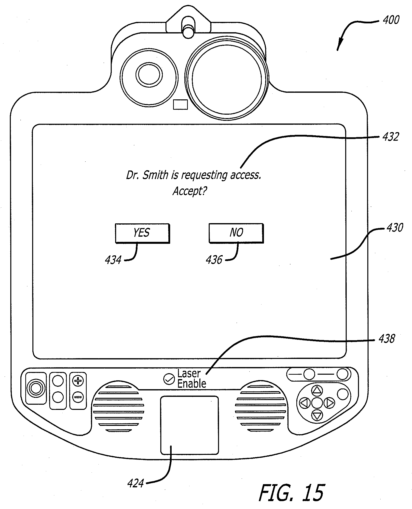
[0073] FIG. 15 shows the robot head 400 displaying a connectivity prompt 430. The prompt 430 may include a message 432 such as "DR. SMITH IS REQUESTING ACCESS. ACCEPT?" and YES 434 and NO 436 graphical buttons. The user of a remote station may select a graphical icon (not shown) that causes the connectivity prompt 430 to appear. Access to the head 400 is not granted until a user at the robot site selects the YES button 434 through the Menu buttons 408. Granting access may then allow the video and audio provided by the head to be transmitted to the remote station. Alternatively, audio may be provided when the prompt 430 is generated but before access is granted. Granting access then provides the remote station with the video feed from the head 400.
[0074] The head 400 may have a laser pointer 440 that can be used to point at objects, etc. The head 400 may include a Laser Enable button 438 that allows the user at the robot site to turn the laser pointer 424 on and off. The user at the robot site may disable the laser pointer, if for example, the laser creates a safety issue.
[0075] The system may have numerous applications. For example, a physician intensivist may initiate a remote presence session with a robot in order to diagnose a patient in an Emergency Room. Upon examining the patient, the physician may realize that the patient assessment will require consultation by a neurology specialist. The intensivist calls the neurologist by phone, asking him to join the session. Upon receiving the telephone request, the neurologist opens his laptop, selects the robot in question from the robot list in the interface, and clicks "Connect". Seeing the message in FIG. 8A, he clicks "OK" and then sees the message in FIG. 8B. The intensivist meanwhile sees the message in FIG. 8C and clicks "Accept". At this point the neurologist receives the robot video and can hear both the robot-side audio and the intensivist.
[0076] The intensivist uses the Live Cursor to point to the patient's face and EEG data on a wall. The neurologist obtains background information that can be provided by a nurse standing next to the patient and in front of the robot, as well as ICU-specific information provided by the intensivist on the master control station. Then, the neurologist can provide an audio assessment of the patient's condition. The intensivist then right-clicks on the thumbnail image of the neurologist in field 288, and clicks the appropriate features in the pull-down menu to allow the neurologist to be seen and heard on the robot. The neurologist can then inform both the patient and family of the condition.
[0077] In another application, a surgeon may be logged onto a robot and performing rounds in patient rooms within a hospital. Residents from hospitals in other cities join the session in the manner described above. The surgeon describes what he is doing to the residents, who may ask questions, and thereby learn the best way to round patients.
[0078] In another application, a hospital CEO may connect to the robot, and telephones three prospective doctors whom the hospital is courting to join the staff. These doctors each join the session as discussed above. The CEO then uses the joystick to drive the robot through the hospital, performing a virtual tour, and discusses the facility with the observer physicians.
[0079] In yet another application, a sales VP of an MRI manufacturing company may connect to a robot in the laboratory wing of a hospital, and then phones the COO of a different hospital to join the session. Upon joining, the sales VP drives the robot into the MRI lab and drives around the MRI machine, describing its features. An on-site MRI technician operates certain controls on the direction of the sales VP. The sales VP explains to the COO the various benefits of purchasing the MRI machine.
[0080] FIGS. 16, 17 and 18 show another embodiment of a tele-presence system 500. The system 500 includes a robot face 400 attached to a boom 502. The boom 502 may extend from the ceiling 504 of a medical facility. The boom 12 may include articulate joints 506 and 508 that provide at least two degrees of freedom and allow a user to move the robot face 400 relative to a medical table 510 such as an operating room ("OR") table.
[0081] The boom 502 may have additional joints 512 and 514 that allow the robot face 400 to be panned and tilted, respectively. The joints 512 and 514 may contain actuators 516 and 518, respectively, that can be remotely actuated.
[0082] As shown in FIG. 19 the cellular phone 50 may include an accelerometer 520 that can sense motion of the phone. The phone may transmit movement commands to the robot that are a function of the sensed movement of the cellular phone 50. For example, the user can move the phone about a Tilt Axis that will cause a corresponding tilt movement of the robot head. Likewise, the user may move the phone about a Spin Axis that induces a corresponding pan movement of the head. When the controlled robot is connected to an overhead boom, this control may allow the user looking down at phone 50 to control the robot head as if they were looking down from the ceiling above the robot head.
[0083] The phone 50 may include a touch screen 522 that causes robot movement that corresponds to the movement of a user's fingers. For example as shown in FIG. 20, the phone may display a cursor 524 that can be moved by having the user drag their fingers across the screen. Movement of the cursor 524 causes a corresponding movement of the robot and/or robot head. The user may use two fingers to rotate about the cursor to cause pan and tilt movement at the robot head. Touching a corner of an image may cause the presentation of a highlighted box 526. The highlighted box can be manipulated to cause the robot camera to zoom in or zoom out while simultaneously, in case of zooming in, pan and tilt the robot head to point in the direction of the center of the zoom. For example, the user can place two fingers on the box and either move their fingers apart to zoom in, or move the fingers together to zoom out.
[0084] The system 10 allows a system user such as a surgical specialist to view a patient on the table 40 and provide remote medical consultation through the remote station 16 and the robot face 14. Personnel at the surgical site can transmit questions and responses through the system back to the system operator. The robot camera 50 allows the specialist to view the patient and enhance the medical consultation. The robot monitor 52 can display the specialist to provide a feeling of presence at the surgical site. The boom 12 allows the personnel to move the robot face 14 into and out of the surgical area.
[0085] The robot face 14 can be retrofitted onto booms that presently exist in medical facilities. For example, some present medical facilities include a monitor attached to a boom. The existing monitor can be replaced with the robot face 14 that is then coupled to the remote station 16.
[0086] While certain exemplary embodiments have been described and shown in the accompanying drawings, it is to be understood that such embodiments are merely illustrative of and not restrictive on the broad invention, and that this invention not be limited to the specific constructions and arrangements shown and described, since various other modifications may occur to those ordinarily skilled in the art.
* * * * *
D00000
D00001
D00002
D00003
D00004
D00005
D00006
D00007
D00008
D00009
D00010
D00011
D00012

D00013

D00014
D00015

D00016

D00017

XML
uspto.report is an independent third-party trademark research tool that is not affiliated, endorsed, or sponsored by the United States Patent and Trademark Office (USPTO) or any other governmental organization. The information provided by uspto.report is based on publicly available data at the time of writing and is intended for informational purposes only.
While we strive to provide accurate and up-to-date information, we do not guarantee the accuracy, completeness, reliability, or suitability of the information displayed on this site. The use of this site is at your own risk. Any reliance you place on such information is therefore strictly at your own risk.
All official trademark data, including owner information, should be verified by visiting the official USPTO website at www.uspto.gov. This site is not intended to replace professional legal advice and should not be used as a substitute for consulting with a legal professional who is knowledgeable about trademark law.