Systems And Methods For Measuring Voltage And Current Within A Welding Torch
Walker; James M.
U.S. patent application number 16/700682 was filed with the patent office on 2020-04-02 for systems and methods for measuring voltage and current within a welding torch. The applicant listed for this patent is Illinois Tool Works Inc.. Invention is credited to James M. Walker.
| Application Number | 20200101552 16/700682 |
| Document ID | / |
| Family ID | 1000004500863 |
| Filed Date | 2020-04-02 |


View All Diagrams
| United States Patent Application | 20200101552 |
| Kind Code | A1 |
| Walker; James M. | April 2, 2020 |
SYSTEMS AND METHODS FOR MEASURING VOLTAGE AND CURRENT WITHIN A WELDING TORCH
Abstract
A retrofit module includes at least one of a current sensing component that has a first circuit or a voltage sensing component that has a second circuit. The current sensing component and the voltage sensing component may be disposed in a torch head of a welding or plasma cutting torch. The current sensing component is configured to measure a welding or plasma cutting current of the torch head, and the voltage sensing component is configured to measure a welding or plasma cutting voltage of the torch head.
| Inventors: | Walker; James M.; (Waupaca, WI) | ||||||||||
| Applicant: |
|
||||||||||
|---|---|---|---|---|---|---|---|---|---|---|---|
| Family ID: | 1000004500863 | ||||||||||
| Appl. No.: | 16/700682 | ||||||||||
| Filed: | December 2, 2019 |
Related U.S. Patent Documents
| Application Number | Filing Date | Patent Number | ||
|---|---|---|---|---|
| 14245870 | Apr 4, 2014 | 10493552 | ||
| 16700682 | ||||
| Current U.S. Class: | 1/1 |
| Current CPC Class: | B23K 10/006 20130101; H05H 1/34 20130101; H05H 2001/3494 20130101; B23K 9/095 20130101; G09B 19/24 20130101; B23K 9/0956 20130101 |
| International Class: | B23K 9/095 20060101 B23K009/095; G09B 19/24 20060101 G09B019/24; H05H 1/34 20060101 H05H001/34; B23K 10/00 20060101 B23K010/00 |
Claims
1. A welding or plasma cutting torch, comprising: a voltage sensing component at least partially disposed within a body of the welding or plasma cutting torch and comprising voltage sensing circuitry, wherein the voltage sensing component is configured to measure a welding or plasma cutting voltage of the welding or plasma cutting torch.
2. The welding or plasma cutting torch of claim 1, wherein the voltage sensing circuitry is configured to convert the measured welding or plasma cutting voltage into an output signal, and to transmit the output signal to a processing system.
3. The welding or plasma cutting torch of claim 1, wherein a welding or plasma cutting system comprises the welding or plasma cutting torch.
4. The welding or plasma cutting torch of claim 3, wherein the welding or plasma cutting system comprises a training system.
5. The welding or plasma cutting torch of claim 3, wherein the welding or plasma cutting system comprises a power source that is not configured to measure a current or a voltage within the power source.
6. The welding or plasma cutting torch of claim 1, wherein the welding or plasma cutting torch comprises a first conductor configured to convey a current through a torch head of the welding or plasma cutting torch, wherein the voltage sensing component comprises a second conductor, and wherein the voltage sensing component is configured to measure a difference between a first voltage of the first conductor and a second voltage of the second conductor, wherein the difference is the welding or plasma cutting voltage.
7. The welding or plasma cutting torch of claim 1, comprising a current sensing component at least partially disposed within the body of the welding or plasma cutting torch and comprising current sensing circuitry, wherein the current sensing component is configured to measure a welding or plasma cutting current of the welding or plasma cutting torch.
8. The welding or plasma cutting torch of claim 7, wherein the current sensing component comprises a magnetic sensor.
9. The welding or plasma cutting torch of claim 8, wherein the magnetic sensor is a Hall sensor.
10. The welding or plasma cutting torch of claim 1, comprising a retrofit module having the voltage sensing component and configured to be retrofit into the welding or plasma cutting torch.
11. A welding or plasma cutting torch, comprising: a current sensing component at least partially disposed within a body of the welding or plasma cutting torch and comprising current sensing circuitry, wherein the current sensing component is configured to measure a welding or plasma cutting current of the welding or plasma cutting torch.
12. The welding or plasma cutting torch of claim 11, wherein the current sensing circuitry is configured to convert the measured welding or plasma cutting current into an output signal, and to transmit the output signal to a processing system.
13. The welding or plasma cutting torch of claim 11, wherein a welding or plasma cutting system comprises the welding or plasma cutting torch.
14. The welding or plasma cutting torch of claim 11, wherein the current sensing component comprises a magnetic sensor.
15. The welding or plasma cutting torch of claim 14, wherein the magnetic sensor comprises a Hall sensor.
16. The welding or plasma cutting torch of claim 15, wherein the current sensing component is disposed on a printed circuit board (PCB), and wherein a surface of the Hall sensor is disposed orthogonally to a magnetic field caused by the welding or plasma cutting current.
17. The welding or plasma cutting torch of claim 15, comprising a welding or plasma cutting conductor configured to convey the welding or plasma cutting current through a torch head of the welding or plasma cutting torch, wherein the current sensing component is disposed within a ferrite core, and wherein the ferrite core is disposed around the welding or plasma cutting conductor.
18. The welding or plasma cutting torch of claim 11, comprising a retrofit module having the current sensing component and configured to be retrofit into the welding or plasma cutting torch.
19. The welding or plasma cutting torch of claim 11, comprising a voltage sensing component at least partially disposed within the body of the welding or plasma cutting torch and comprising voltage sensing circuitry, wherein the voltage sensing component is configured to measure a welding or plasma cutting voltage of the welding or plasma cutting torch.
20. A retrofit module, comprising at least one of: a current sensing component comprising a first circuit; or a voltage sensing component comprising a second circuit; wherein the current sensing component and the voltage sensing component are configured to be disposed in a torch head of a welding or plasma cutting torch, wherein the current sensing component is configured to measure a welding or plasma cutting current of the torch head, and wherein the voltage sensing component is configured to measure a welding or plasma cutting voltage of the torch head.
Description
CROSS REFERENCE TO RELATED APPLICATIONS
[0001] This application is a Continuation application of U.S. Non-Provisional patent application Ser. No. 14/245,870 entitled "Systems and Methods for Measuring Voltage and Current within a Welding Torch" filed Apr. 4, 2014, which is herein incorporated by reference in its entirety.
BACKGROUND
[0002] The invention relates generally to welding and, more particularly, to systems and methods for measuring voltage and current within a welding torch.
[0003] Welding is a process that has increasingly become utilized in various industries and applications. Such processes may be automated in certain contexts, although a large number of applications continue to exist for manual welding operations. In both cases, such welding operations rely on a variety of types of equipment to ensure the supply of welding consumables (e.g., wire feed, shielding gas, etc.) is provided to the weld in appropriate amounts at the desired time.
[0004] In preparation for performing manual welding operations, welding operators may be trained using a welding system (e.g., a welding training system). The welding system may be designed to train welding operators with the proper techniques for performing various welding operations. Certain welding systems may use various training methods. As may be appreciated, these training systems may be expensive to acquire and operate. Accordingly, welding training institutions may only acquire a limited number of such training systems. Furthermore, certain welding systems may not adequately train welding operators to perform high quality welds.
BRIEF DESCRIPTION
[0005] In one embodiment, a welding or plasma cutting torch may include a voltage sensing component at least partially disposed in a body of the welding or plasma cutting torch. The voltage sensing component has voltage sensing circuitry and is configured to measure a welding or plasma cutting voltage of the welding or plasma cutting torch.
[0006] In another embodiment, a welding or plasma cutting torch may include a current sensing component at least partially disposed in a body of the welding or plasma cutting torch. The current sensing component has current sensing circuitry and is configured to measure the welding or plasma cutting current of the welding or plasma cutting torch.
[0007] In another embodiment, a retrofit module may include at least one of a current sensing component that has a first circuit or a voltage sensing component that has a second circuit. The current sensing component and the voltage sensing component may be at least partially disposed in a body of a welding or plasma cutting torch. The current sensing component is configured to measure a welding or plasma cutting current of the welding or plasma cutting torch, and the voltage sensing component is configured to measure a welding or plasma cutting voltage of the welding or plasma cutting torch.
DRAWINGS
[0008] These and other features, aspects, and advantages of the present invention will become better understood when the following detailed description is read with reference to the accompanying drawings in which like characters represent like parts throughout the drawings, wherein:
[0009] FIG. 1 is a block diagram of an embodiment of a welding system in accordance with aspects of the present disclosure;
[0010] FIG. 2 is a block diagram of an embodiment of portions of the welding system of FIG. 1 in accordance with aspects of the present disclosure;
[0011] FIG. 2A is a schematic diagram of an embodiment of circuitry of the welding torch of FIG. 1 in accordance with aspects of the present disclosure;
[0012] FIG. 3 is a perspective view of an embodiment of the welding torch of FIG. 1 in accordance with aspects of the present disclosure;
[0013] FIG. 4 is a perspective view of an embodiment of the welding stand of FIG. 1 in accordance with aspects of the present disclosure;
[0014] FIG. 5 is a perspective view of an embodiment of a calibration device in accordance with aspects of the present disclosure;
[0015] FIG. 6 is a perspective view of an embodiment of a fixture assembly in accordance with aspects of the present disclosure;
[0016] FIG. 7 is a perspective view of a welding wire stickout calibration tool in accordance with aspects of the present disclosure;
[0017] FIG. 8 is a top view of the welding wire stickout calibration tool of FIG. 7 in accordance with aspects of the present disclosure;
[0018] FIG. 9 is an embodiment of a method for calibrating wire stickout from a welding torch in accordance with aspects of the present disclosure;
[0019] FIG. 10 is a perspective view of an embodiment of a welding consumable having physical marks in accordance with aspects of the present disclosure;
[0020] FIG. 11 is a perspective view of an embodiment of welding wire having physical marks in accordance with aspects of the present disclosure;
[0021] FIG. 12 is a perspective view of an embodiment of a vertical arm assembly of the welding stand of FIG. 1 in accordance with aspects of the present disclosure;
[0022] FIG. 13 is a perspective view of an embodiment of an overhead welding arm assembly in accordance with aspects of the present disclosure;
[0023] FIG. 14 is a block diagram of an embodiment of welding software having multiple training modes in accordance with aspects of the present disclosure;
[0024] FIG. 15 is a block diagram of an embodiment of a virtually reality mode of welding software in accordance with aspects of the present disclosure;
[0025] FIG. 16 is an embodiment of a method for integrating training results data in accordance with aspects of the present disclosure;
[0026] FIG. 17 is an embodiment of a chart illustrating multiple sets of welding data for a welding operator in accordance with aspects of the present disclosure;
[0027] FIG. 18 is an embodiment of a chart illustrating welding data for a welder compared to welding data for a class in accordance with aspects of the present disclosure;
[0028] FIG. 19 is a block diagram of an embodiment of a data storage system for storing certification status data in accordance with aspects of the present disclosure;
[0029] FIG. 20 is an embodiment of a screen illustrating data corresponding to a weld in accordance with aspects of the present disclosure;
[0030] FIG. 21 is an embodiment of a screen illustrating a discontinuity analysis of a weld in accordance with aspects of the present disclosure;
[0031] FIG. 22 is a block diagram of an embodiment of a welding instructor screen of welding software in accordance with aspects of the present disclosure;
[0032] FIG. 23 is an embodiment of a method for weld training using augmented reality in accordance with aspects of the present disclosure;
[0033] FIG. 24 is an embodiment of another method for weld training using augmented reality in accordance with aspects of the present disclosure;
[0034] FIG. 25 is a block diagram of an embodiment of a welding torch in accordance with aspects of the present disclosure;
[0035] FIG. 26 is an embodiment of a method for providing vibration feedback to a welding operator using a welding torch in accordance with aspects of the present disclosure;
[0036] FIG. 27 is a graph of an embodiment of two patterns each including a different frequency for providing vibration feedback to a welding operator in accordance with aspects of the present disclosure;
[0037] FIG. 28 is a graph of an embodiment of two patterns each including a different modulation for providing vibration feedback to a welding operator in accordance with aspects of the present disclosure;
[0038] FIG. 29 is a graph of an embodiment of two patterns each including a different amplitude for providing vibration feedback to a welding operator in accordance with aspects of the present disclosure;
[0039] FIG. 30 is a perspective view of an embodiment of a welding torch having spherical markers that may be used for tracking the welding torch in accordance with aspects of the present disclosure;
[0040] FIG. 31 is an embodiment of a method for displaying on a display of a welding torch a welding parameter in relation to a threshold in accordance with aspects of the present disclosure;
[0041] FIG. 32 is an embodiment of a set of screenshots of a display of a welding torch for showing a welding parameter in relation to a threshold in accordance with aspects of the present disclosure;
[0042] FIG. 33 is an embodiment of a method for tracking a welding torch in a welding system using at least four markers in accordance with aspects of the present disclosure;
[0043] FIG. 34 is an embodiment of a method for detecting the ability for a processor to communicate with a welding torch in accordance with aspects of the present disclosure;
[0044] FIG. 35 is an embodiment of a method for calibrating a curved weld joint that may be used with a welding system in accordance with aspects of the present disclosure;
[0045] FIG. 36 is a diagram of an embodiment of a curved weld joint in accordance with aspects of the present disclosure;
[0046] FIG. 37 is an embodiment of a method for tracking a multi-pass welding operation in accordance with aspects of the present disclosure;
[0047] FIG. 38 is a perspective view of an embodiment of a welding stand in accordance with aspects of the present disclosure;
[0048] FIG. 39 is a cross-sectional view of an embodiment of a welding surface of the welding stand of FIG. 38 in accordance with aspects of the present disclosure;
[0049] FIG. 40 is a cross-sectional view of an embodiment of a sensing device having a removable cover in accordance with aspects of the present disclosure;
[0050] FIG. 41 is a perspective view of an embodiment of a calibration tool in accordance with aspects of the present disclosure;
[0051] FIG. 42 is a perspective view of the calibration tool of FIG. 41 having an outer cover removed in accordance with aspects of the present disclosure;
[0052] FIG. 43 is a side view of an embodiment of a pointed tip of a calibration tool in accordance with aspects of the present disclosure;
[0053] FIG. 44 is a side view of an embodiment of a rounded tip of a calibration tool in accordance with aspects of the present disclosure;
[0054] FIG. 45 is a side view of an embodiment of a rounded tip of a calibration tool having a small pointed tip in accordance with aspects of the present disclosure;
[0055] FIG. 46 is an embodiment of a method for detecting a calibration point in accordance with aspects of the present disclosure;
[0056] FIG. 47 is an embodiment of a method for determining a welding score based on a welding path in accordance with aspects of the present disclosure;
[0057] FIG. 48 is an embodiment of a method for transitioning between welding modes using a user interface of a welding torch in accordance with aspects of the present disclosure;
[0058] FIG. 49 is a perspective view of an embodiment of the voltage sensing component and the current sensing component within a welding torch in accordance with aspects of the present disclosure;
[0059] FIG. 50 is a side view of an embodiment of the voltage sensing component within a welding system in accordance with aspects of the present disclosure;
[0060] FIG. 51 is a schematic of an embodiment of the voltage sensing circuitry within the voltage sensing component in accordance with aspects of the present disclosure;
[0061] FIG. 52 is a side view of an embodiment of the current sensing component within a welding system in accordance with aspects of the present disclosure;
[0062] FIG. 53 is a diagram of the operation of a Hall sensor of the current sensing component in accordance with aspects of the present disclosure;
[0063] FIG. 54 is a schematic of an embodiment of the current sensing circuitry within the current sensing component in accordance with aspects of the present disclosure;
[0064] FIG. 55 is a perspective view of an embodiment of the current sensing component within a welding torch in accordance with aspects of the present disclosure;
[0065] FIG. 56 is an exploded view of an embodiment of the current sensing component in relation to a welding conductor of the welding torch in accordance with aspects of the present disclosure; and
[0066] FIG. 57 is a top view of an embodiment of a retrofit kit in accordance with aspects of the present disclosure.
DETAILED DESCRIPTION
[0067] In welding training systems, a variety of parameters related to a welding operation may be measured and conveyed to the operator as some form of feedback. These parameters may include the welding voltage and welding current of the welding operation. However, existing training systems do not directly measure the welding voltage and welding current conveyed through a conductor within the welding torch. At best, existing welding systems may include a power supply that measures the voltage and current within the power supply.
[0068] The embodiments described herein include a voltage sensing component and a current sensing component disposed in a welding torch that may be used to directly measure the welding voltage and the welding current within the welding torch. The voltage sensing component may include two leads, one coupled to the welding conductor and the other coupled to a second conductor within the welding system. The voltage sensing component may determine the welding voltage by computing the difference between the voltages of the welding conductor and the second conductor. The current sensing component includes a Hall sensor that measures a Hall voltage that is representative of the welding current and uses the Hall voltage to determine the welding current. The voltage sensing component and the current sensing component also include circuitry that converts (e.g., scales) the welding voltage and the welding current, respectively, to a signal suitable for input to a computer system, for example, as a feedback signal. The voltage sensing component and the current sensing component described herein may also be packaged as a retrofit kit, which may be installed in existing welding torches.
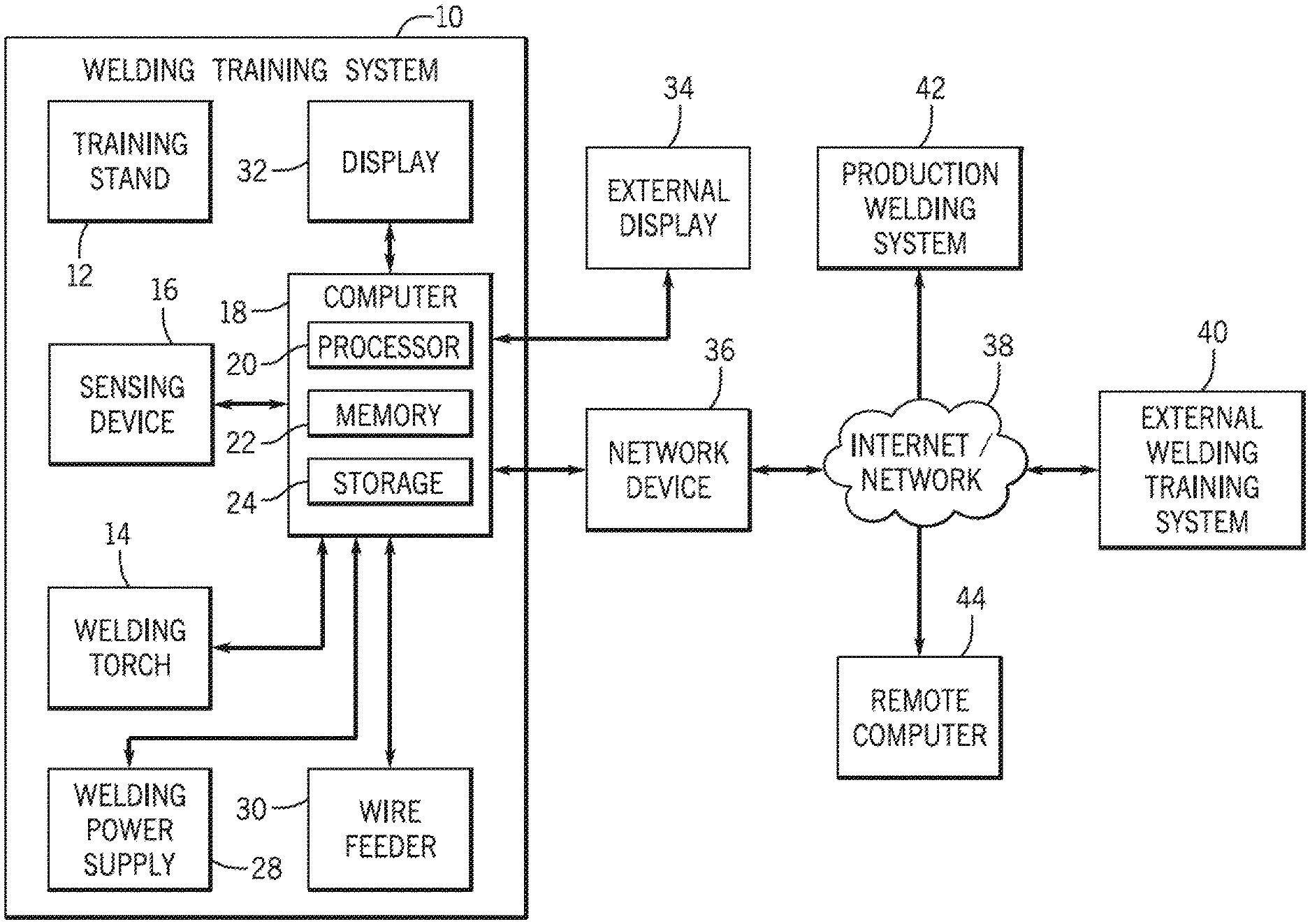
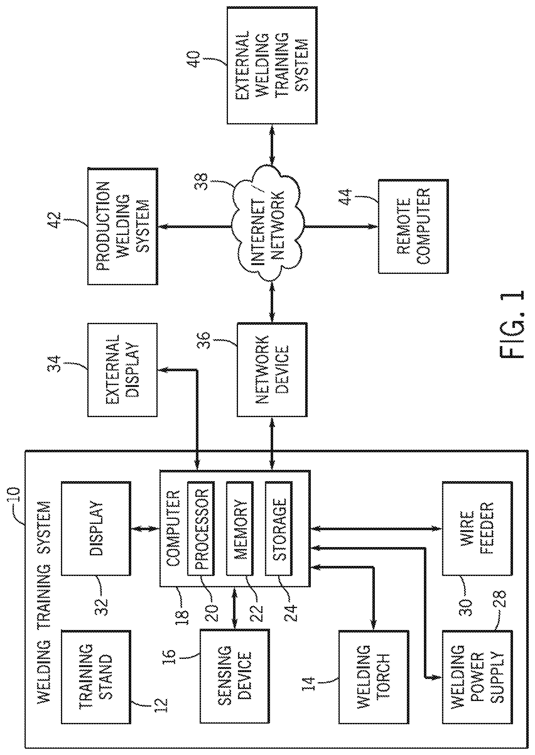
[0069] Turning now to FIG. 1, a block diagram of an embodiment of a welding system 10 is depicted. As used herein, a welding system may include any suitable welding related system, including, but not limited to, a welding training system, a live welding system, a simulated welding system, a virtual reality welding system, and so forth. It should be noted that, while primarily described herein as being a welding system 10, it will be appreciated that in other embodiments, the welding system 10 may indeed be any welding-type system, such as a plasma cutting system, or any other system where an arc may be delivered via a torch to perform a welding-type operation, such as welding, plasma cutting, and so forth. The welding system 10 includes a welding stand 12 for providing support for various training devices. For example, the stand 12 may be configured to support a welding surface, a workpiece, a fixture, one or more training arms, and so forth. The welding system 10 also includes a welding torch 14 that may be used by a welding operator (e.g., welding student) to perform welding operations (e.g., training operations). As described in greater detail below, the welding torch 14 may be configured with a user interface configured to receive inputs from the welding operator, control circuitry configured to process the inputs, and a communication interface configured to provide the inputs to another device. Furthermore, the welding torch 14 may include one or more display and/or indicators to provide data to the welding operator. Moreover, the welding system 10 includes a sensing device 16 (e.g., sensor, sensing assembly, and so forth) used to sense a position of one or more welding devices and/or to sense an orientation of one or more welding devices. For example, the sensing device 16 may be used to sense a position and/or an orientation of the stand 12, the welding torch 14, a welding surface, a workpiece, a fixture, one or more training arms, and so forth. The sensing device 16 may include any suitable sensing device, such as a motion sensing device or a motion tracking device. Furthermore, the sensing device 16 may include one or more cameras, such as one or more infrared cameras, one or more visible spectrum cameras, one or more high dynamic range (HDR) cameras, and so forth.
[0070] The sensing device 16 is communicatively coupled to a computer 18. The sensing device 16 is configured to provide data (e.g., image data, sensed data, six degrees of freedom (6DOF) data, etc.) to the computer 18. Furthermore, the sensing device 16 may be configured to receive data (e.g., configuration data, setup data, commands, register settings, etc.) from the computer 18. The computer 18 includes one or more processors 20, memory devices 22, and storage devices 24. The processor(s) 20 may be used to execute software, such as welding software, image processing software, sensing device software, and so forth. Moreover, the processor(s) 20 may include one or more microprocessors, such as one or more "general-purpose" microprocessors, one or more special-purpose microprocessors and/or application specific integrated circuits (ASICS), or some combination thereof. For example, the processor(s) 20 may include one or more reduced instruction set (RISC) processors.
[0071] The storage device(s) 24 (e.g., nonvolatile storage) may include ROM, flash memory, a hard drive, or any other suitable optical, magnetic, or solid-state storage medium, or a combination thereof. The storage device(s) 24 may store data (e.g., data corresponding to a welding operation, video and/or parameter data corresponding to a welding operation, etc.), instructions (e.g., software or firmware for the welding system, the sensing device 16, etc.), and any other suitable data. As will be appreciated, data that corresponds to a welding operation may include a video recording of the welding operation, a simulated video, an orientation of the welding torch 14, a position of the welding torch 14, a work angle, a travel angle, a distance between a contact tip of the welding torch 14 and a workpiece, a travel speed, a proximity, a voltage, a current, a traversed path, a discontinuity analysis, welding device settings, and so forth.
[0072] The memory device(s) 22 may include a volatile memory, such as random access memory (RAM), and/or a nonvolatile memory, such as read-only memory (ROM). The memory device(s) 22 may store a variety of information and may be used for various purposes. For example, the memory device(s) 22 may store processor-executable instructions (e.g., firmware or software) for the processor(s) 20 to execute, such as instructions for a welding training simulation and/or for the sensing device 16. In addition, a variety of control regimes for various welding processes, along with associated settings and parameters may be stored in the storage device(s) 24 and/or memory device(s) 22, along with code configured to provide a specific output (e.g., initiate wire feed, enable gas flow, capture welding current data, detect short circuit parameters, determine amount of spatter, etc.) during operation. The welding power supply 28 may be used to provide welding power to a live-arc welding operation, and the wire feeder 30 may be used to provide welding wire to the live-arc welding operation.
[0073] The welding system 10 includes a display 32 for displaying data and/or screens associated with welding (e.g., to display data corresponding to a welding software). For example, the display 32 may provide a graphical user interface to a welding operator (e.g., welding instructor, welding student). The graphical user interface may provide various screens to enable the welding instructor to organize a class, provide assignments to the class, analyze assignments performed by the class, provide assignments to an individual, analyze assignments performed by the individual, add, change, and/or delete parameters for a welding assignment, and so forth. Furthermore, the graphical user interface may provide various screens to enable a welding operator (e.g., welding student) to perform a welding assignment, view results from prior welding assignments, and so forth. In certain embodiments, the display 32 may be a touch screen display configured to receive touch inputs, and to provide data corresponding to the touch inputs to the computer 18.
[0074] An external display 34 is coupled to the computer 18 to enable an individual located remotely from the welding system 10 to view data corresponding to the welding system 10. Furthermore, a network device 36 is coupled to the computer 18 to enable the computer 18 to communicate with other devices connected to the Internet or another network 38 (e.g., for providing test results to another device and/or for receiving test results from another device). For example, the network device 36 may enable the computer 18 to communicate with an external welding system 40, a production welding system 42, and/or a remote computer 44. As may be appreciated, the welding system 10 described herein may be used to train welding students in a cost effective manner. Furthermore, the welding system 10 is configured to integrate real welding with simulated welding in a manner that prepares welding students for high quality production welding.
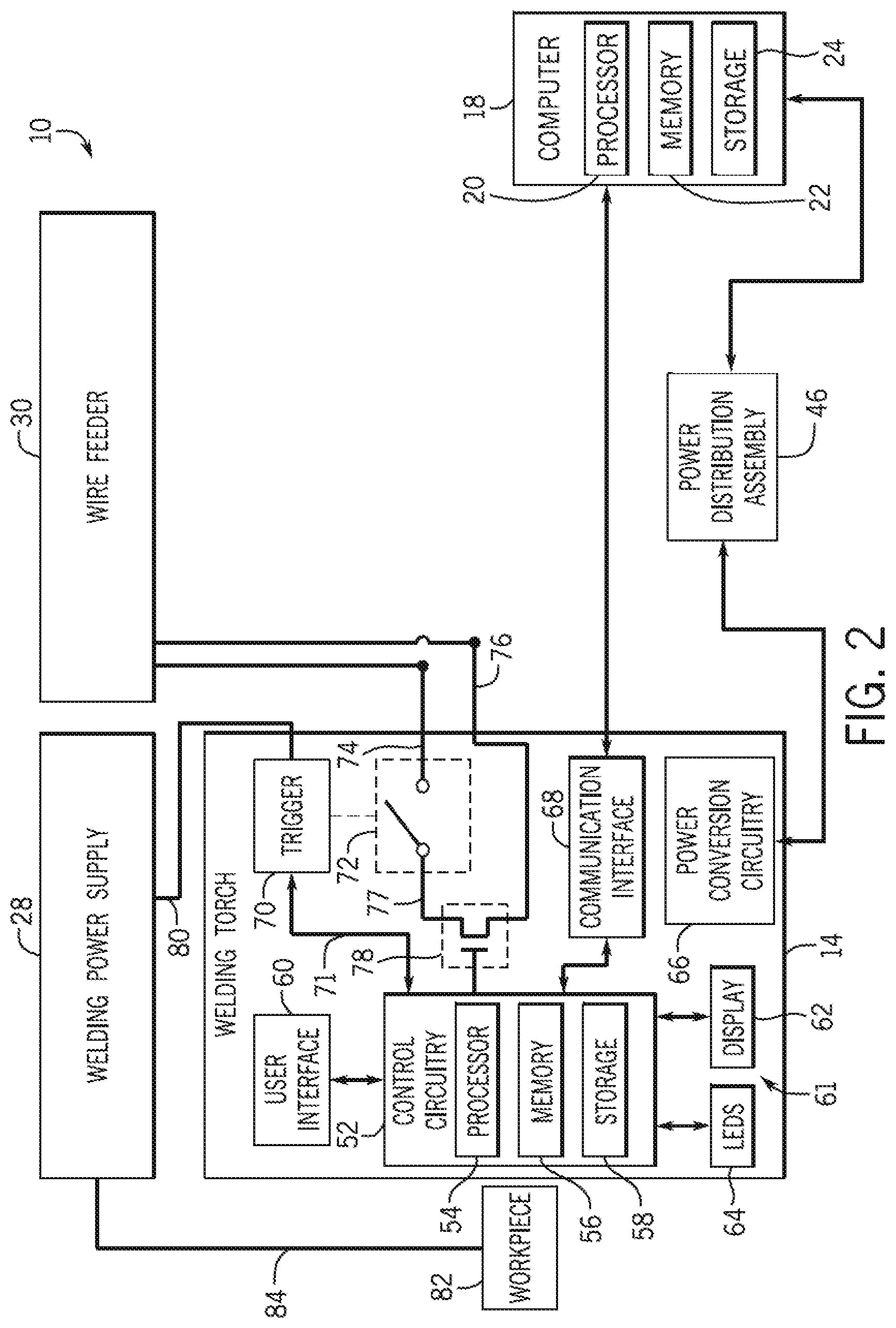
[0075] FIG. 2 is a block diagram of an embodiment of portions of the welding system 10 of FIG. 1. As illustrated, a power distribution assembly 46 provides power to the welding torch 14 and the computer 18. Moreover, the welding torch 14 includes control circuitry 52 configured to control the operation of the welding torch 14. In the illustrated embodiment, the control circuitry 52 includes one or more processors 54, memory devices 56, and storage devices 58. In other embodiments, the control circuitry 52 may not include the processors 54, the memory devices 56, and/or the storage devices 58. The processor(s) 54 may be used to execute software, such as welding torch software. Moreover, the processor(s) 54 may be similar to the processor(s) 20 described previously. Furthermore, the memory device(s) 56 may be similar to the memory device(s) 22, and the storage device(s) 58 may be similar to the storage device(s) 24.
[0076] The welding torch 14 includes a user interface 60 to enable a welding operator (e.g., welding student, welding instructor, etc.) to interact with the welding torch 14 and/or to provide inputs to the welding torch 14. For example, the user interface 60 may include buttons, switches, touch screens, touchpads, and so forth. The inputs provided to the welding torch 14 by the welding operator may be provided to the computer 18. For example, the inputs provided to the welding torch 14 may be used to control welding software being executed by the computer 18. As such, the welding operator may use the user interface 60 on the welding torch 14 to navigate the welding software screens, setup procedures, data analysis, welding courses, make selections within the welding software, configure the welding software, and so forth. Thus, the welding operator can use the welding torch 14 to control the welding software (e.g., the welding operator does not have to put down the welding torch 14 to use a different input device). The welding torch 14 also includes visual indicators 61, such as a display 62 and LEDs 64. The visual indicators 61 may be configured to indicate or display data and/or images corresponding to a weld, welding training, and/or welding software. For example, the visual indicators 61 may be configured to indicate a welding torch orientation, a welding torch travel speed, a welding torch position, a contact tip to workpiece distance, a proximity of the welding torch 14 in relation to the workpiece, an aim of the welding torch 14 (e.g., at what point the welding torch 14 is directed), training information for the welding operator, and so forth. Moreover, the visual indicators 61 may be configured to provide visual indications before a weld, during a weld, and/or after a weld. In certain embodiments, the LEDs 64 may illuminate to facilitate their detection by the sensing device 16. In such embodiments, the LEDs 64 may be positioned to enable the sensing device 16 to determine a position and/or an orientation of the welding torch 14 based on a spatial position of the LEDs 64.
[0077] In certain embodiments, the welding torch 14 includes power conversion circuitry 66 configured to receive power from the data reporting device 26 (e.g., or another device), and to convert the received power for powering the welding torch 14. In certain embodiments, the welding torch 14 may receive power that is already converted and/or does not utilize power conversion. Moreover, in some embodiments, the welding torch 14 may be powered by a battery or any suitable powering mechanism. The welding torch 14 also includes a communication interface 68 (e.g., RS-232 driver) to facilitate communication between the welding torch 14 and the data reporting device 26 (or another device). In the illustrated embodiment, the welding torch 14 may communicate with the computer 18 by providing data to the data reporting device 26 using the communication interfaces 50 and 68, then the data reporting device 26 communicates the data to the computer 18. Accordingly, inputs provided to the welding torch 14 may be provided to the computer 18. In certain embodiments, the welding torch 14 may provide inputs to the computer 18 by communicating directly with the computer 18.
[0078] The welding torch 14 includes a trigger 70 configured to mechanically actuate a trigger switch 72 between an open position (as illustrated) and a closed position. The trigger 70 provides a conductor 71 to carry a signal to the control circuitry 52 to indicate whether the trigger switch 72 is in the open position or the closed position. The wire feeder 30, the welding power supply 28, the computer 18, and/or the data reporting device 26 may determine whether there is continuity through the welding torch 14 across a first welding conductor 74 and a second welding conductor 76. The trigger switch 72 is electrically coupled between the first welding conductor 74 and the second welding conductor 76. Continuity across the first welding conductor 74 and the second welding conductor 76 may be determined by applying a voltage across the welding conductors 74 and 76, applying a current across the welding conductors 74 and 76, measuring a resistance across the welding conductors 74 and 76, and so forth. In certain embodiments, portions of the first welding conductor 74 and/or portions of the second welding conductor 76 may be disposed within a connector of the welding torch 14. Furthermore, in certain embodiments, the arrangement of switches and/or conductors within the welding torch 14 may be different than illustrated in FIG. 2.
[0079] The welding power supply 28 may determine whether to enable welding power to flow through the welding torch 14 based on whether there is continuity across the welding conductors 74 and 76. For example, the welding power supply 28 may enable welding power to flow through the welding torch 14 while there is continuity across the welding conductors 74 and 76, and the welding power supply 28 may block welding power from flowing through the welding torch 14 while there is an open circuit across the welding conductors 74 and 76. Furthermore, the wire feeder 30 may provide welding wire to the welding torch 14 while there is continuity across the welding conductors 74 and 76, and may block welding wire from being provided to the welding torch 14 while there is an open circuit across the welding conductors 74 and 76. Moreover, the computer 18 may use the continuity across the welding conductors 74 and 76 and/or the position of the trigger 70 or trigger switch 72 to start and/or stop a welding operation, a welding simulation, data recording, and so forth.
[0080] With the trigger switch 72 in the open position, there is an open circuit across the welding conductors 74 and 76, thus, the open position of the trigger switch 72 blocks electron flow between the welding conductors 74 and 76. Accordingly, the welding power supply 28 may block welding power from flowing through the welding torch 14 and the wire feeder 30 may block welding wire from being provided to the welding torch 14. Pressing the trigger 70 directs the trigger switch 72 to the closed position where the trigger switch 72 remains as long as the trigger 70 is pressed. With the trigger switch 72 in the closed position, there is continuity between the first welding conductor 74 and a conductor 77 electrically connected to the trigger switch 72 and a training switch 78.
[0081] The training switch 78 is electrically coupled between the first welding conductor 74 and the second welding conductor 76. Moreover, the training switch 78 is electrically controlled by the control circuitry 52 to an open position or to a closed position. In certain embodiments, the training switch 78 may be any suitable electrically controlled switch, such as a transistor, relay, etc. The control circuitry 52 may selectively control the training switch 78 to the open position or to the closed position. For example, while welding software of the welding system 10 is operating in a live-arc mode, the control circuitry 52 may be configured to control the training switch 78 to the closed position to enable a live welding arc while the trigger 70 is pressed. In contrast, while welding software of the welding system 10 is operating in any mode other than the live-arc mode (e.g., simulation, virtual reality, augmented reality, etc.), the control circuitry 52 may be configured to control the training switch 78 to the open position to block a live welding arc (by blocking electron flow between the welding conductors 74 and 76).
[0082] In certain embodiments, the training switch 78 may default to the open position, thereby establishing an open circuit across the welding conductors 74 and 76. As may be appreciated, while the training switch 78 is in the open position, there will be an open circuit across the welding conductors 74 and 76 regardless of the position of the trigger switch 72 (e.g., electron flow between the welding conductors 74 and 76 is blocked by the open position of the training switch 78). However, while the training switch 78 is controlled to the closed position, and the trigger switch 72 is in the closed position, conductivity is established between the welding conductors 74 and 76 (e.g., electron flow between the welding conductors 74 and 76 is enabled). Accordingly, the welding power supply 28 may enable welding power to flow through the welding torch 14 only while the training switch 78 is in the closed position and while the trigger switch 72 is in the closed position. For example, welding power may flow from the welding power supply 28, through a weld cable 80, the welding torch 14, a workpiece 82, and return to the welding power supply 28 via a work cable 84 (e.g., electrode-negative, or straight polarity). Conversely, welding power may flow from the welding power supply 28, through the work cable 84, the workpiece 82, the welding torch 14, and return to the welding power supply 28 via the weld cable 80 (e.g., electrode-positive, or reverse polarity).
[0083] As may be appreciated, the training switch 78 may be physically located in any suitable portion of the welding system 10, such as the data reporting device 26, the computer 18, and so forth. Furthermore, in certain embodiments, the functionality of the training switch 78 may be replaced by any suitable hardware and/or software in the welding system 10.
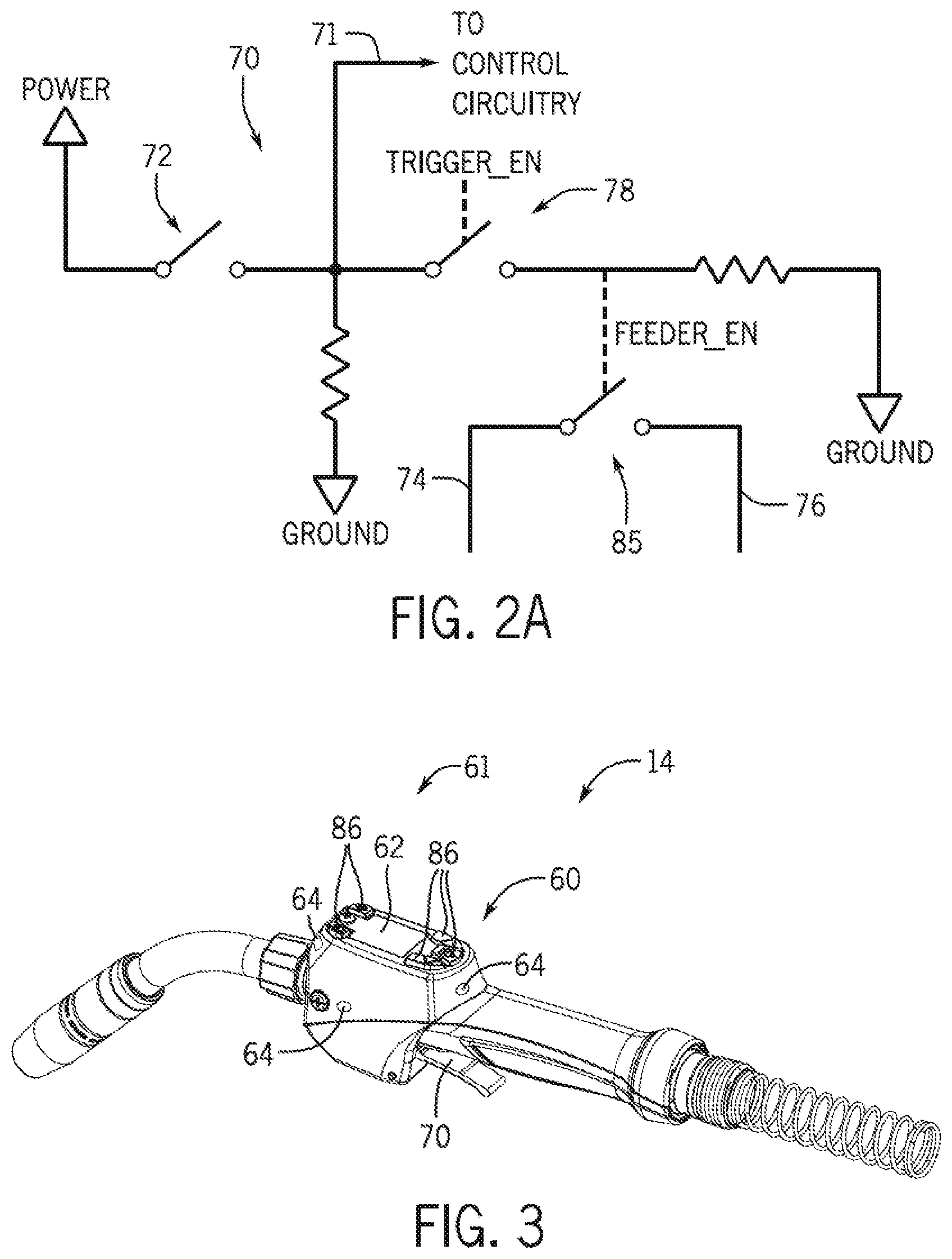
[0084] FIG. 2A is a schematic diagram of an embodiment of circuitry of the welding torch 14 of FIG. 1. In the illustrated embodiment, the trigger switch 72 selectively connects a power supplying conductor (e.g., voltage source, etc.) to the conductor 71. Accordingly, while the trigger switch 72 is open, no voltage is applied to the conductor 71, and while the trigger switch 72 is closed, voltage from the power supplying conductor is supplied to the conductor 71. A trigger enable signal (e.g., TRIGGER_EN) may be provided by the control circuitry 52 to selectively control the training switch 78, and thereby control a feeder enable switch 85. For example, when the trigger enable signal controls the training switch 78 to an open position, no voltage is applied to the feeder enable switch 85 (e.g., via the FEEDER_EN connection), thereby maintaining the feeder enable switch 85 in the open position. Conversely, when the trigger enable signal controls the training switch 78 to a closed position, voltage is applied to the feeder enable switch 85, thereby controlling the feeder enable switch 85 to the closed position. With the feeder enable switch 85 in the closed position, conductivity between the welding conductors 74 and 76 is established. While one example of welding torch 14 circuitry is provided, any suitable circuitry may be used within the welding torch 14. A microprocessor of the control circuitry 52 may pulse the trigger enable signal at predetermined intervals to provide an indication to detection circuitry of the control circuitry 52 that the trigger enable signal is working properly. If the detection circuitry does not detect the trigger enable signal, the trigger may not be enabled.
[0085] FIG. 3 is a perspective view of an embodiment of the welding torch 14 of FIGS. 1 and 2. As illustrated, the user interface 60 includes multiple buttons 86 which may be used to provide inputs to the welding torch 14. For example, the buttons 86 may enable a welding operator to navigate through welding software. Furthermore, the welding torch 14 includes the display 62 which may show the welding operator data corresponding to the welding software, data corresponding to a welding operation, and so forth. As illustrated, the LEDs 64 may be positioned at various locations on the welding torch 14. Accordingly, the LEDs 64 may be illuminated to facilitate detection by the sensing device 16.
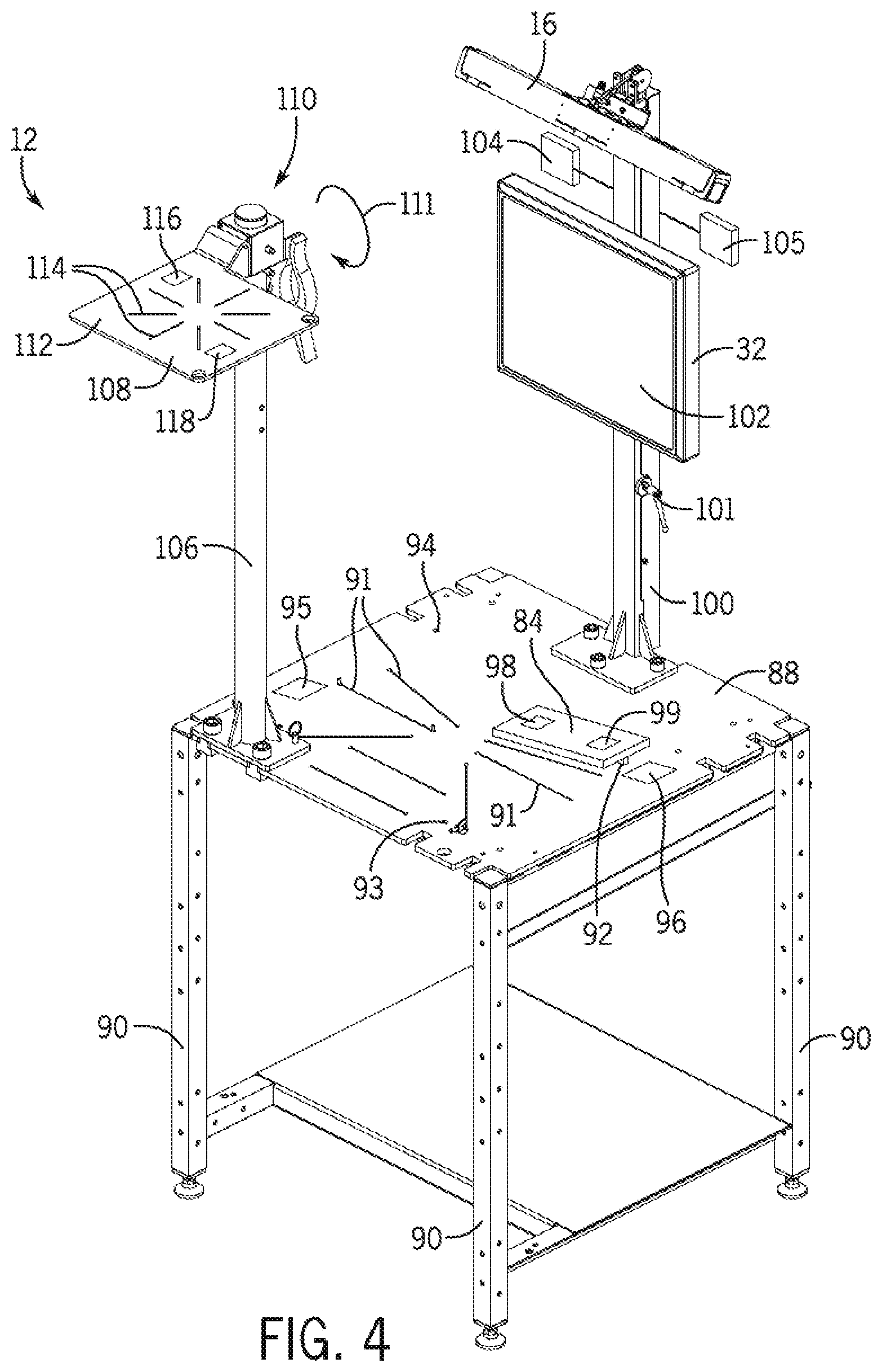
[0086] FIG. 4 is a perspective view of an embodiment of the stand 12 of FIG. 1. The stand 12 includes a welding surface 88 on which live welds (e.g., real welds, actual welds) and/or simulated welds may be performed. Legs 90 provide support to the welding surface 88. In certain embodiments, the welding surface 88 may include slots 91 to aid a welding operator in positioning and orienting the workpiece 82. In certain embodiments, the position and orientation of the workpiece 82 may be provided to welding software of the welding system 10 to calibrate the welding system 10. For example, a welding operator may provide an indication to the welding software identifying which slot 91 of the welding surface 88 the workpiece 82 is aligned with. Furthermore, a predefined welding assignment may direct the welding operator to align the workpiece 82 with a particular slot 91. In certain embodiments, the workpiece 82 may include an extension 92 configured to extend into one or more of the slots 91 for alignment of the workpiece 82 with the one or more slots 91. As may be appreciated, each of the slots 91 may be positioned at a location corresponding to a respective location defined in the welding software.
[0087] The welding surface 88 includes a first aperture 93 and a second aperture 94. The first and second apertures 93 and 94 may be used together to determine a position and/or an orientation of the welding surface 88. As may be appreciated, in certain embodiments at least three apertures may be used to determine the position and/or the orientation of the welding surface 88. In some embodiments, more than three apertures may be used to determine the position and/or the orientation of the welding surface 88. The first and second apertures 93 and 94 may be positioned at any suitable location on the welding surface 88, and may be any suitable size. In certain embodiments, the position and/or orientation of the welding surface 88 relative to the sensing device 16 may be calibrated using the first and second apertures 93 and 94. For example, as described in greater detail below, a calibration device configured to be sensed by the sensing device 16 may be inserted into the first aperture 93, or touched to the first aperture 93. While the calibration device is inserted into, or touching, the first aperture 93, a user input provided to the welding software (or other calibration software) may indicate that the calibration device is inserted into the first aperture 93. As a result, the welding software may establish a correlation between a first data set (e.g., calibration data) received from the sensing device 16 (e.g., position and/or orientation data) at a first time and the location of first aperture 93. The calibration device may next be inserted into the second aperture 94, or touched to the second aperture 94. While the calibration device is inserted into, or touching, the second aperture 94, a user input provided to the welding software may indicate that the calibration device is inserted into the second aperture 94. As a result, the welding software may establish a correlation between a second data set (e.g., calibration data) received from the sensing device 16 at a second time and the location of second aperture 94. Thus, the welding software may be able to calibrate the position and/or orientation of the welding surface 88 relative to the sensing device 16 using the first data set received at the first time and the second data set received at the second time.
[0088] The welding surface 88 also includes a first marker 95 and a second marker 96. The first and second markers 95 and 96 may be used together to determine a position and/or an orientation of the welding surface 88. As may be appreciated, in certain embodiments at least three markers may be used to determine the position and/or the orientation of the welding surface 88. In some embodiments, more than three markers may be used to determine the position and/or the orientation of the welding surface 88. The first and second markers 95 and 96 may be formed from any suitable material. Moreover, in certain embodiments, the first and second markers 95 and 96 may be built into the welding surface 88, while in other embodiments, the first and second markers 95 and 96 may be attached to the welding surface 88. For example, the first and second markers 95 and 96 may be attached to the welding surface 88 using an adhesive and/or the first and second markers 95 and 96 may be stickers. The first and second markers 95 and 96 may have any suitable shape, size, and/or color. Furthermore, in certain embodiments, the first and second markers 95 and 96 may be a reflector formed from a reflective material. The first and second markers 95 and 96 may be used by the welding system 10 to calibrate the position and/or orientation of the welding surface 88 relative to the sensing device 16 without a separate calibration device. Accordingly, the first and second markers 95 and 96 are configured to be detected by the sensing device 16. In certain embodiments, the first and second markers 95 and 96 may be positioned at predetermined locations on the welding surface 88. Furthermore, the welding software may be programmed to use the predetermined locations to determine the position and/or the orientation of the welding surface 88. In other embodiments, the location of the first and second markers 95 and 96 may be provided to the welding software during calibration. With the first and second markers 95 and 96 on the welding surface 88, the sensing device 16 may sense the position and/or orientation of the first and second markers 95 and 96 relative to the sensing device 16. Using this sensed data in conjunction with the location of the first and second markers 95 and 96 on the welding surface 88, the welding software may be able to calibrate the position and/or orientation of the welding surface 88 relative to the sensing device 16. In some embodiments, the welding surface 88 may be removable and/or reversible. In such embodiments, the welding surface 88 may be flipped over, such as if the welding surface 88 become worn.
[0089] In the illustrated embodiment, the workpiece 82 includes a first marker 98 and a second marker 99. The first and second markers 98 and 99 may be used together to determine a position and/or an orientation of the workpiece 82. As may be appreciated, at least two markers are used to determine the position and/or the orientation of the workpiece 82. In certain embodiments, more than two markers may be used to determine the position and/or the orientation of the workpiece 82. The first and second markers 98 and 99 may be formed from any suitable material. Moreover, in certain embodiments, the first and second markers 98 and 99 may be built into the workpiece 82, while in other embodiments, the first and second markers 98 and 99 may be attached to the workpiece 82. For example, the first and second markers 98 and 99 may be attached to the workpiece 82 using an adhesive and/or the first and second markers 98 and 99 may be stickers. As a further example, the first and second markers 98 and 99 may be clipped or clamped onto the workpiece 82. The first and second markers 98 and 99 may have any suitable shape, size, and/or color. Furthermore, in certain embodiments, the first and second markers 98 and 99 may be a reflector formed from a reflective material. The first and second markers 98 and 99 may be used by the welding system 10 to calibrate the position and/or orientation of the workpiece 82 relative to the sensing device 16 without a separate calibration device. Accordingly, the first and second markers 98 and 99 are configured to be detected by the sensing device 16. In certain embodiments, the first and second markers 98 and 99 may be positioned at predetermined locations on the workpiece 82. Furthermore, the welding software may be programmed to use the predetermined locations to determine the position and/or the orientation of the workpiece 82. In other embodiments, the location of the first and second markers 98 and 99 may be provided to the welding software during calibration. With the first and second markers 98 and 99 on the workpiece 82, the sensing device 16 may sense the position and/or orientation of the first and second markers 98 and 99 relative to the sensing device 16. Using this sensed data in conjunction with the location of the first and second markers 98 and 99 on the workpiece 82, the welding software may be able to calibrate the position and/or orientation of the workpiece 82 relative to the sensing device 16. While the markers 95, 96, 98, and 99 have been described herein as being detected by the sensing device 16, in certain embodiments, the markers 95, 96, 98, and 99 may indicate locations where a calibration device is to be touched for calibration using the calibration device, as described previously.
[0090] The stand 12 includes a first arm 100 extending vertically from the welding surface 88 and configured to provide support for the sensing device 16 and the display 32. A knob 101 is attached to the first arm 100 and may be used to adjust an orientation of the sensing device 16 relative to the first arm 100. For example, as the knob 101 is adjusted, mechanical components extending through the first arm 100 may adjust an angle of the sensing device 16. The display 32 includes a cover 102 to protect the display 32 from welding emissions that may occur during a live welding operation. The cover 102 may be made from any suitable material, such as a transparent material, a polymer, and so forth. By using a transparent material, a welding operator may view the display 32 while the cover 102 is positioned in front of the display 32, such as before, during, and/or after a welding operation. A camera 104 may be coupled to the first arm 100 for recording welding operations. In certain embodiments, the camera 104 may be a high dynamic range (HDR) camera. Furthermore, an emitter 105 may be coupled to the first arm 100. The emitter 105 may be used to calibrate the position and/or orientation of the welding surface 88 relative to the sensing device 16. For example, the emitter 105 may be configured to emit a visible pattern onto the welding surface 88. The visible pattern may be shown onto the welding surface 88. Furthermore, the visible pattern may be detected by the sensing device 16 to calibrate the position and/or the orientation of the welding surface 88 relative to the sensing device 16. For example, based on particular features of the visible pattern alignments and/or orientations may be determined by the sensing device 16 and/or the welding software. Moreover, the visible pattern emitted by the emitter 105 may be used to facilitate positioning of the workpiece 82 on the welding surface 88.
[0091] The stand 12 also includes a second arm 106 extending vertically from the welding surface 88 and configured to provide support for a welding plate 108 (e.g., vertical welding plate, horizontal welding plate, overhead welding plate, etc.). The second arm 106 may be adjustable to facilitate overhead welding at different heights. Moreover, the second arm 106 may be manufactured in a number of different ways to facilitate overhead welding at different heights. The welding plate 108 is coupled to the second arm 106 using a mounting assembly 110. The mounting assembly 110 facilitates rotation of the welding plate 108 as illustrated by arrow 111. For example, the welding plate 108 may be rotated from extending generally in the horizontal plane (e.g., for overhead welding), as illustrated, to extend generally in the vertical plane (e.g., for vertical welding). The welding plate 108 includes a welding surface 112. The welding surface 112 includes slots 114 that may aid a welding operator in positioning the workpiece 82 on the welding surface 112, similar to the slots 91 on the welding surface 88. In certain embodiments, the position of the workpiece 82 may be provided to welding software of the welding system 10 to calibrate the welding system 10. For example, a welding operator may provide an indication to the welding software identifying which slot 114 of the welding surface 112 the workpiece 82 is aligned with. Furthermore, a predefined welding assignment may direct the welding operator to align the workpiece 82 with a particular slot 114. In certain embodiments, the workpiece 82 may include an extension configured to extend into one or more of the slots 114 for alignment of the workpiece 82 with the one or more slots 114. As may be appreciated, each of the slots 114 may be positioned at a location corresponding to a respective location defined in the welding software.
[0092] The welding surface 112 also includes a first marker 116 and a second marker 118. The first and second markers 116 and 118 may be used together to determine a position and/or an orientation of the welding surface 112. As may be appreciated, at least two markers are used to determine the position and/or the orientation of the welding surface 112. In certain embodiments, more than two markers may be used to determine the position and/or the orientation of the welding surface 112. The first and second markers 116 and 118 may be formed from any suitable material. Moreover, in certain embodiments, the first and second markers 116 and 118 may be built into the welding surface 112 (or another part of the welding plate 108), while in other embodiments, the first and second markers 116 and 118 may be attached to the welding surface 112 (or another part of the welding plate 108). For example, the first and second markers 116 and 118 may be attached to the welding surface 112 using an adhesive and/or the first and second markers 116 and 118 may be stickers. As a further example, the first and second markers 116 and 118 may be clipped or clamped onto the welding surface 112. In some embodiments, the first and second markers 116 and 118 may be integrated into a holding clamp that is clamped onto a welding coupon. The first and second markers 116 and 118 may have any suitable shape, size, and/or color. Furthermore, in certain embodiments, the first and second markers 116 and 118 may be a reflector formed from a reflective material.
[0093] The first and second markers 116 and 118 may be used by the welding system 10 to calibrate the position and/or orientation of the welding surface 112 relative to the sensing device 16 without a separate calibration device. Accordingly, the first and second markers 116 and 118 are configured to be detected by the sensing device 16. In certain embodiments, the first and second markers 116 and 118 may be positioned at predetermined locations on the welding surface 112. Furthermore, the welding software may be programmed to use the predetermined locations to determine the position and/or the orientation of the welding surface 112. In other embodiments, the location of the first and second markers 116 and 118 may be provided to the welding software during calibration. With the first and second markers 116 and 118 on the welding surface 112, the sensing device 16 may sense the position and/or orientation of the first and second markers 116 and 118 relative to the sensing device 16. Using this sensed data in conjunction with the location of the first and second markers 116 and 118 on the welding surface 112, the welding software may be able to calibrate the position and/or orientation of the welding surface 112 relative to the sensing device 16. Furthermore, the sensing device 16 may sense and/or track the first and second markers 116 and 118 during a weld to account for any movement of the welding plate 108 that may occur during the weld. While the markers 116 and 118 have been described herein as being detected by the sensing device 16, in certain embodiments, the markers 116 and 118 may indicate locations where a calibration device is to be touched or inserted for calibration using the calibration device, as described previously.
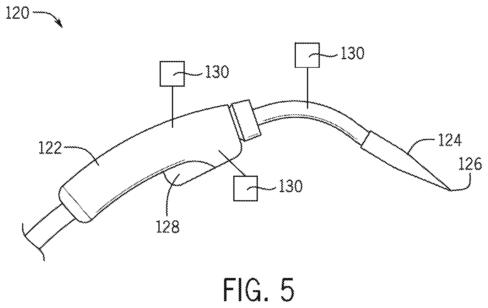
[0094] FIG. 5 is a perspective view of an embodiment of a calibration device 120. In some embodiments, the calibration device 120 is shaped like a torch and may be used for calibrating the position and/or orientation of the welding surfaces 88 and 112 relative to the sensing device 16. In other embodiments, the calibration device 120 may be used for calibrating the position and/or orientation of a welding joint. The calibration device 120 includes a handle 122 and a nozzle 124. The nozzle 124 includes a pointed end 126 that may be used to touch a location for calibration and/or to be inserted into an aperture for calibration. The calibration device 120 also includes a user interface 128 that enables the welding operator to provide input corresponding to a time that the calibration device 120 is touching a location for calibration and/or is being inserted into an aperture for calibration. Moreover, in certain embodiments, the calibration device 120 includes markers 130 configured to be sensed by the sensing device 16. As illustrate, the markers 130 extend from the calibration device 120. However, in other embodiments, the markers 130 may not extend from the calibration device 120. The markers 130 may be any suitable marker configured to be detected by the sensing device 16. Moreover, the markers 130 may be any suitable size, shape, and/or color.
[0095] During calibration, the sensing device 16 may sense a position of the calibration device 120 and/or an orientation of the calibration device 120. The position and/or orientation of the calibration device 120 may be used by the welding software to determine a position and/or orientation of one or more of the welding surfaces 88 and 112 relative to the sensing device 16, a position and/or orientation of the workpiece 82 relative to the sensing device 16, a position and/or orientation of a fixture relative to the sensing device 16, and so forth. Thus, the calibration device 120 may facilitate calibration of the welding system 10. In some embodiments, a tray may be positioned beneath the welding surface 88 for storing the calibration device 120. Moreover, in certain embodiments live welding may be disabled if the calibration device 120 is able to be tracked by the sensing device 16 (e.g., to block spatter from contacting the calibration device 120).
[0096] FIG. 6 is a perspective view of an embodiment of a fixture assembly 132. The fixture assembly 132 may be positioned on the welding surface 88 and/or the welding surface 112, and may secure the workpiece 82 thereon. In certain embodiments, the fixture assembly 132 may be configured to align with one or more of the slots 92 and 114. In other embodiments, the fixture assembly 132 may be placed at any location on the welding surface 88 and/or the welding surface 122. The fixture assembly 132 also includes a first marker 134 and a second marker 136. The first and second markers 134 and 136 may be used together to determine a position and/or an orientation of the fixture assembly 132. As may be appreciated, at least two markers are used to determine the position and/or the orientation of the fixture assembly 132. The first and second markers 134 and 136 may be formed from any suitable material. Moreover, in certain embodiments, the first and second markers 134 and 136 may be built into the fixture assembly 132, while in other embodiments, the first and second markers 134 and 136 may be attached to the fixture assembly 132. For example, the first and second markers 134 and 136 may be attached to the fixture assembly 132 using an adhesive and/or the first and second markers 134 and 136 may be stickers. The first and second markers 134 and 136 may have any suitable shape, size, and/or color. Furthermore, in certain embodiments, the first and second markers 134 and 136 may be a reflector formed from a reflective material. The first and second markers 134 and 136 may be used by the welding system 10 to calibrate the position and/or orientation of the fixture assembly 132 relative to the sensing device 16 without a separate calibration device. Accordingly, the first and second markers 134 and 136 are configured to be detected by the sensing device 16. In certain embodiments, the first and second markers 134 and 136 may be positioned at predetermined locations on the fixture assembly 132. Furthermore, the welding software may be programmed to use the predetermined locations to determine the position and/or the orientation of the fixture assembly 132. In other embodiments, the location of the first and second markers 134 and 136 may be provided to the welding software during calibration. With the first and second markers 134 and 136 on the fixture assembly 132, the sensing device 16 may sense the position and/or orientation of the first and second markers 134 and 136 relative to the sensing device 16. Using this sensed data in conjunction with the location of the first and second markers 134 and 136 on the fixture assembly 132, the welding software may be able to calibrate the position and/or orientation of the fixture assembly 132 relative to the sensing device 16. While the first and second markers 134 and 136 have been described herein as being detected by the sensing device 16, in certain embodiments, the first and second markers 134 and 136 may indicate locations where a calibration device is to be touched or inserted for calibration using the calibration device 120, as described previously.
[0097] In the illustrated embodiment, the fixture assembly 132 is configured to secure a lower portion 138 of the workpiece 82 to an upper portion 140 of the workpiece 82 for performing a lap weld. In other embodiments, the fixture assembly 132 may be configured to secure portions of the workpiece 82 for performing a butt weld, a fillet weld, and so forth, to aid a welding operator in performing a weld. The fixture assembly 132 includes vertical arms 142 extending from a base 143. A cross bar 144 extends between the vertical arms 142, and is secured to the vertical arms 142. Adjustment mechanisms 146 (e.g., knobs) may be adjusted to direct locking devices 148 toward the workpiece 82 for securing the workpiece 82 between the locking devices 148 and the base 143 of the fixture assembly 132. Conversely, the adjustment mechanisms 146 may be adjusted to direct the locking devices 148 away from the workpiece 82 for removing the workpiece 82 from being between the locking devices 148 and the base 143. Accordingly, the workpiece 82 may be selectively secured to the fixture assembly 132.
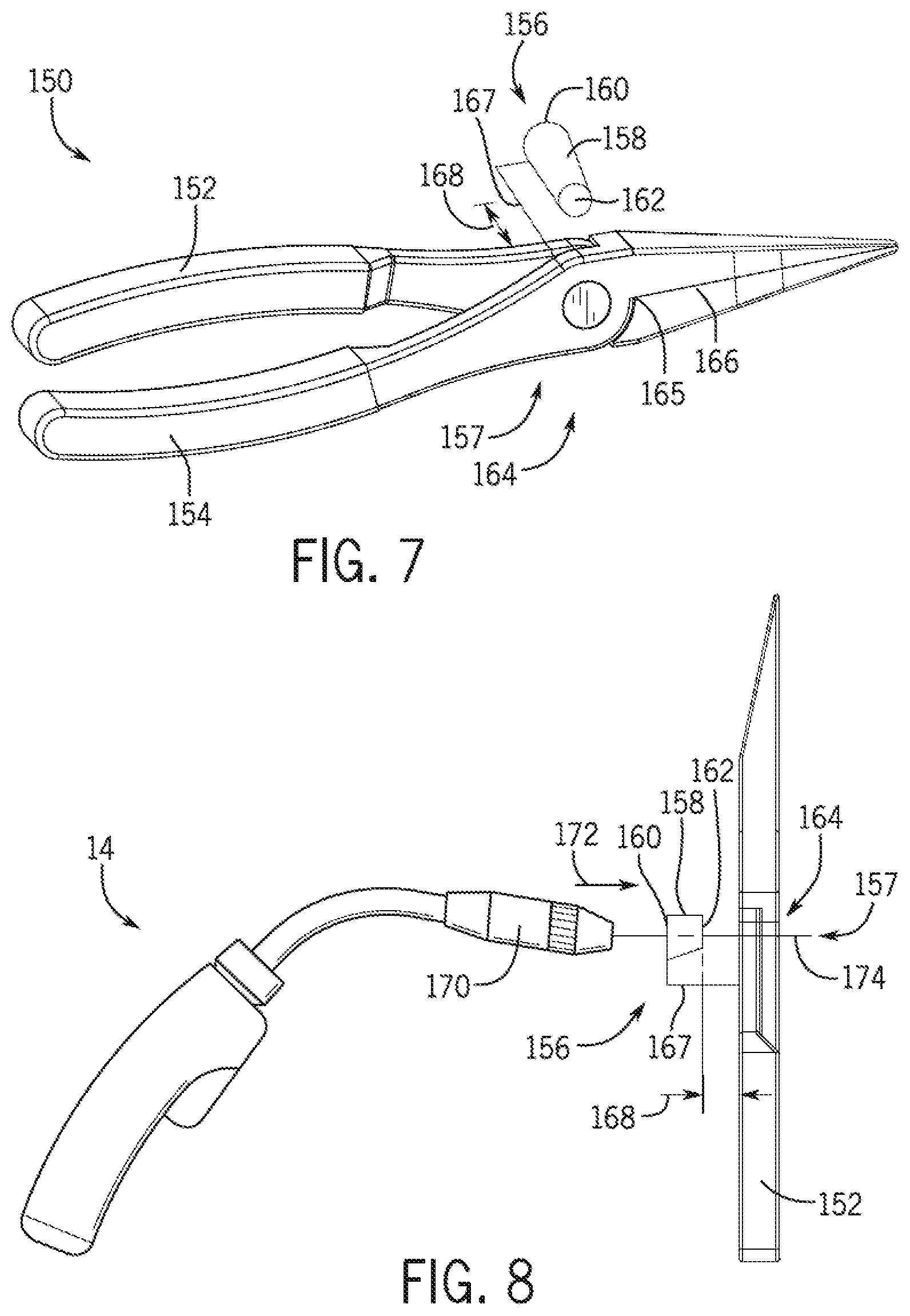
[0098] FIG. 7 is a perspective view of a welding wire stickout calibration tool 150. The tool 150 is configured to calibrate a length of welding wire extending out of a torch nozzle to a selectable length. Accordingly, the tool 150 includes a first handle 152 and a second handle 154. The tool 150 also includes a torch nozzle holder 156 attached to a central portion 157 of the tool 150 and extending outward from the central portion 157 a selected distance. In the illustrated embodiment, the torch nozzle holder 156 has a generally cylindrical body 158 (e.g., cup shape); however, in other embodiments, the body 158 of the torch nozzle holder 156 may have any suitable shape. Moreover, the torch nozzle holder 156 is configured to receive the torch nozzle through a nozzle inlet 160 such that the torch nozzle extends into the body 158. Furthermore, the torch nozzle holder 156 includes an opening 162 configured to enable welding wire to extend out the end of the torch nozzle holder 156, and to block the torch nozzle from extending through the opening 162. As the torch nozzle extends into the torch nozzle holder 156, the welding wire extends out of the opening 162 of the torch nozzle holder 156 toward a blade assembly 164 of the tool 150. The blade assembly 164 includes one or more sides 165 and 166 configured to contact the welding wire. In certain embodiments, both of sides 165 and 166 include blades to cut opposing sides of the welding wire, while in other embodiments, only one of the sides 165 and 166 includes a blade to cut one side of the welding wire and the other side includes a surface to which the blade is directed toward. For calibrating the length of the welding wire, the welding wire may extend through the opening 162 and into the blade assembly 164. The welding wire may be cut to a selectable length by pressing the first handle 152 and the second handle 154 toward one another, thereby calibrating the length of wire extending from the torch nozzle. The calibration length may be selected using an adjustment mechanism 167 to adjust a distance 168 between the blade assembly 164 and the opening 162 of the torch nozzle holder 156. Thus, using the tool 150, the length of wire extending from the torch nozzle may be calibrated.
[0099] FIG. 8 is a top view of the welding wire stickout calibration tool 150 of FIG. 7. As illustrated, the welding torch 14 may be used with the tool 150. Specifically, a nozzle 170 of the welding torch 14 may be inserted into the torch nozzle holder 156 in a direction 172. Welding wire 174 extending from the welding torch 14 is directed through the nozzle inlet 160, the opening 162, and the blade assembly 164. Accordingly, the first and second handles 152 and 154 may be pressed together to cut the welding wire 174 to the distance 168 (e.g., the calibration length) set by the adjustment mechanism 167.
[0100] FIG. 9 is an embodiment of a method 176 for calibrating wire stickout from the welding torch 14. The tool 150 may be used to calibrate the length of welding wire 174 extending from the nozzle 170 using a variety of methods. In the method 176, the adjustment mechanism 167 of the welding wire stickout calibration tool 150 may be adjusted for a selected welding wire 174 length (block 178). For example, the distance 168 of the torch nozzle holder 156 from the tool 150 may be set to a range of between approximately 0.5 to 2.0 cm, 1.0 to 3.0 cm, and so forth. The welding torch 14 may be inserted into the torch nozzle holder 156 of the tool 150, such that the nozzle 170 of the welding torch 14 abuts the torch nozzle holder 156, and that the welding wire 174 extends through the opening 162 of the torch nozzle holder 156 (block 180). In certain embodiments, the welding wire 174 may be long enough to extend through the blade assembly 164. However, if the welding wire 174 does not extend through the blade assembly 164, a welding operator may actuate the trigger 70 of the welding torch 14 to feed welding wire 174 such that the welding wire 174 extends through the blade assembly 164 (block 182). Accordingly, the welding operator may compress handles 152 and 154 of the tool 150 to cut the welding wire 174 extending through the blade assembly 164 and thereby calibrate the length of the welding wire 174 (block 184).
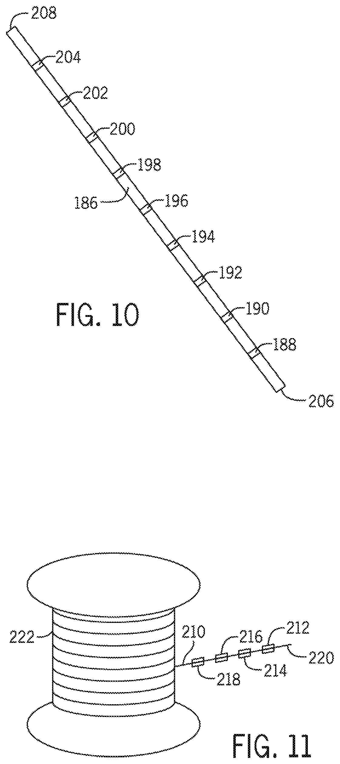
[0101] FIG. 10 is a perspective view of an embodiment of a welding consumable 186 having physical marks. The welding consumable 186 may be any suitable welding consumable, such as a welding stick, welding rod, or a welding electrode. The welding consumable 186 includes physical marks 188, 190, 192, 194, 196, 198, 200, 202, and 204. The physical marks 188, 190, 192, 194, 196, 198, 200, 202, and 204 may be any suitable physical mark. For example, the physical marks 188, 190, 192, 194, 196, 198, 200, 202, and 204 may include a bar code, an image, a shape, a color, text, a set of data, and so forth. In certain embodiments, the physical marks 188, 190, 192, 194, 196, 198, 200, 202, and 204 may be laser etched. Furthermore, in certain embodiments, the physical marks 188, 190, 192, 194, 196, 198, 200, 202, and 204 may be visible with the natural eye (e.g., within the visible spectrum), while in other embodiments the physical marks 188, 190, 192, 194, 196, 198, 200, 202, and 204 may not be visible with the natural eye (e.g., not within the visible spectrum).
[0102] Each of the physical marks 188, 190, 192, 194, 196, 198, 200, 202, and 204 indicates a location on the welding consumable 186 relative to either a first end 206, or a second end 208 of the welding consumable 186. For example, the physical mark 188 may indicate a distance from the first end 206, a distance from the second end 208, or some other location relative to the welding consumable 186. In certain embodiments, the physical marks 188, 190, 192, 194, 196, 198, 200, 202, and 204 may indicate a number that corresponds to the first end 206 and/or the second end 208. For example, the physical mark 188 may indicate a number "1" indicating that it is the first physical mark from the first end 206 and/or the physical mark 188 may indicate a number "9" indicating that it is the ninth physical mark from the second end 208. A processing device may use a lookup table to determine a distance from the first end 206 or the second end 208 based on the number indicated by the physical mark.
[0103] A camera-based detection system, which may include the sensing device 16, or another type of system is configured to detect the physical marks 188, 190, 192, 194, 196, 198, 200, 202, and 204 during live arc welding or a welding simulation. Moreover, the camera-based detection system is configured to determine a remaining length of the welding consumable 186, a consumed length of the welding consumable 186, a rate of use of the welding consumable 186, a dipping rate of the welding consumable 186, and so forth, based on the detected physical marks. Accordingly, data corresponding to use of the welding consumable 186 may be tracked by the welding system 10 for training and/or analysis.
[0104] FIG. 11 is a perspective view of an embodiment of welding wire 210 having physical marks 212, 214, 216, and 218. The physical marks 212, 214, 216, and 218 may be any suitable physical mark. For example, the physical marks 212, 214, 216, and 218 may include a bar code, an image, a shape, text, a set of data, and so forth. In certain embodiments, the physical marks 212, 214, 216, and 218 may be laser etched. Furthermore, in certain embodiments, the physical marks 212, 214, 216, and 218 may be visible with the natural eye (e.g., within the visible spectrum), while in other embodiments the physical marks 212, 214, 216, and 218 may not be visible with the natural eye (e.g., not within the visible spectrum).
[0105] Each of the physical marks 212, 214, 216, and 218 indicates a location on the welding wire 210 relative to either a first end 220, or a second end 222 of the welding wire 210. For example, the physical mark 212 may indicate a distance from the first end 220, a distance from the second end 222, or some other location relative to the welding wire 210. In certain embodiments, the physical marks 212, 214, 216, and 218 may indicate a number that corresponds to the first end 220 and/or the second end 222. For example, the physical mark 212 may indicate a number "1" indicating that it is the first physical mark from the first end 220 and/or the physical mark 212 may indicate a number "4" indicating that it is the fourth physical mark from the second end 222. A processing device may use a lookup table to determine a distance from the first end 220 or the second end 222 based on the number indicated by the physical mark.
[0106] A camera-based detection system, which may include the sensing device 16, or another type of system is configured to detect the physical marks 212, 214, 216, and 218 during live arc welding or a welding simulation. Moreover, the camera-based detection system is configured to determine a remaining length of the welding wire 210, a consumed length of the welding wire 210, a rate of use of the welding wire 210, a dipping rate of the welding wire 210, and so forth, based on the detected physical marks. Accordingly, data corresponding to use of the welding wire 210 may be tracked by the welding system 10 for training and/or analysis.
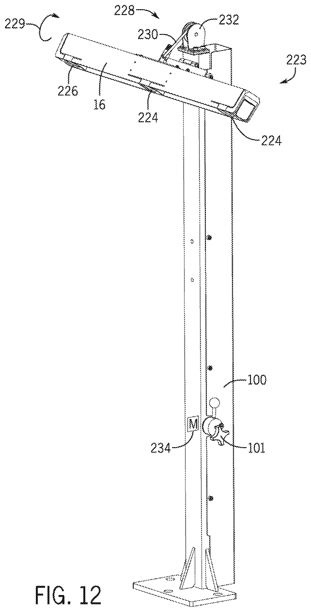
[0107] FIG. 12 is a perspective view of an embodiment of a vertical arm assembly 223 of the stand 12 of FIG. 4. As illustrated, the sensing device 16 is attached to the first arm 100. Furthermore, the sensing device 16 includes cameras 224, and an infrared emitter 226. However, in other embodiments, the sensing device 16 may include any suitable number of cameras, emitters, and/or other sensing devices. A pivot assembly 228 is coupled to the first arm 100 and to the sensing device 16, and enables an angle of the sensing device 16 to be adjusted while the sensing device 16 rotates as illustrated by arrow 229. As may be appreciated, adjusting the angle of the sensing device 16 relative to the first arm 100 changes the field of view of the sensing device 16 (e.g., to change the portion of the welding surface 88 and/or the welding surface 112 sensed by the sensing device 16).
[0108] A cord 230 extends between the knob 101 and the sensing device 16. The cord 230 is routed through a pulley 232 to facilitate rotation of the sensing device 16. Thus, a welding operator may rotate the knob 101 to manually adjust the angle of the sensing device 16. As may be appreciated, the combination of the cord 230 and the pulley 232 is one example of a system for rotating the sensing device 16. It should be noted that any suitable system may be used to facilitate rotation of the sensing device 16. While one embodiment of a knob 101 is illustrated, it may be appreciated that any suitable knob may be used to adjust the angle of the sensing device 16. Furthermore, the angle of the sensing device 16 may be adjusted using a motor 234 coupled to the cord 230. Accordingly, a welding operator may operate the motor 234 to adjust the angle of the sensing device 16. Moreover, in certain embodiments, control circuitry may be coupled to the motor 234 and may control the angle of the sensing device 16 based on a desired field of view of the sensing device 16 and/or based on tracking of an object within the field of view of the sensing device 16.
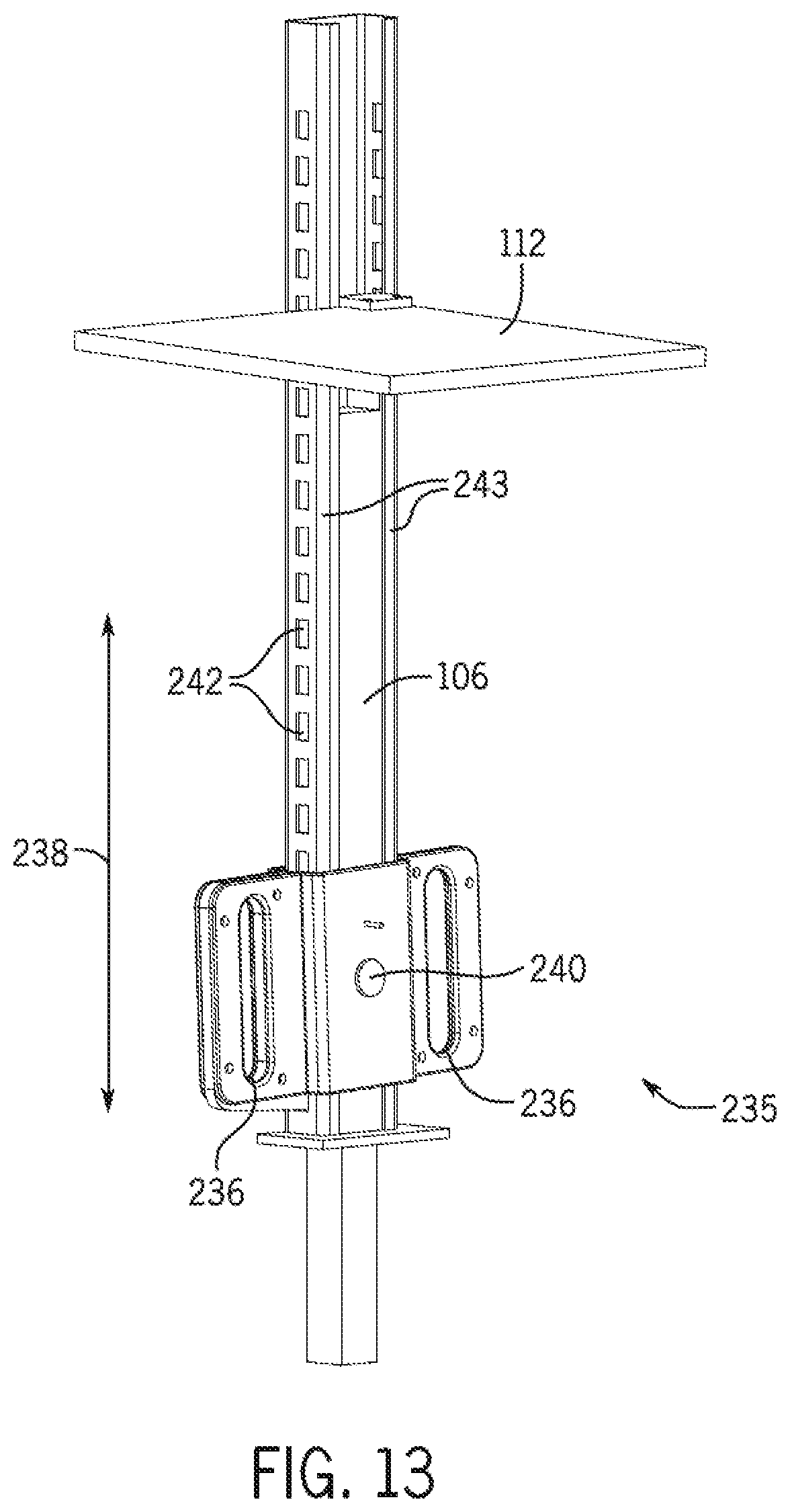
[0109] FIG. 13 is a perspective view of an embodiment of an overhead welding arm assembly 235. The overhead welding arm assembly 235 illustrates one embodiment of a manufacturing design that enables the second arm 106 to have an adjustable height. Accordingly, as may be appreciated, the second arm 106 may be manufactured to have an adjustable height in a number of ways. As illustrated, the overhead welding assembly 235 includes handles 236 used to vertically raise and/or lower the second arm 106 as illustrated by arrows 238. The overhead welding arm assembly 235 includes a locking device 240 to lock the second arm 106 at a desired height. For example, the locking device 240 may include a button that is pressed to disengage a latch configured to extend into openings 242, thus unlocking the second arm 106 from being secured to side rails 243. With the second arm 106 unlocked from the side rails 243, the handles 236 may be vertically adjusted to a desired height, thereby adjusting the plate 112 to a desired height. As may be appreciated, releasing the button may result in the latch extending into the openings 242 and locking the second arm 106 to the side rails 243. As may be appreciated, the locking device 240 may operate manually as described and/or the locking device 240 may be controlled by a control system (e.g., automatically controlled). Furthermore, the second arm 106 may be vertically raised and/or lowered using the control system. For example, in certain embodiments, the welding software may control the second arm 106 to move to a desired position automatically. Thus, the plate 112 may be adjusted to a desired height for overhead welding.
[0110] FIG. 14 is a block diagram of an embodiment of welding software 244 (e.g., welding training software) of the welding system 10 having multiple modes. As illustrated, the welding software 244 may include one or more of a live-arc mode 246 configured to enable training using a live (e.g., actual) welding arc, a simulation mode 248 configured to enable training using a welding simulation, a virtual reality (VR) mode 250 configured to enable training using a VR simulation, and/or an augmented reality mode 252 configured to enable training using augmented reality simulation.
[0111] The welding software 244 may receive signals from an audio input 254. The audio input 254 may be configured to enable a welding operator to operate the welding software 244 using audible commands (e.g., voice activation). Furthermore, the welding software 244 may be configured to provide an audio output 256 and/or a video output 258. For example, the welding software 244 may provide audible information to a welding operator using the audio output 256. Such audible information may include instructions for configuring (e.g., setting up) the welding system 10, real-time feedback provided to a welding operator during a welding operation, instructions to a welding operator before performing a welding operation, instructions to a welding operator after performing a welding operation, warnings, and so forth.
[0112] FIG. 15 is a block diagram of an embodiment of the VR mode 250 of the welding software 244. The VR mode 250 is configured to provide a welding operator with a VR simulation 260. The VR simulation 260 may be displayed to a welding operator through a VR headset, VR glasses, a VR display, or any suitable VR device. The VR simulation 260 may be configured to include a variety of virtual objects, such as the objects illustrated in FIG. 15, that enable interaction between a welding operator and a selected virtual object of the variety of virtual objects within the VR simulation 260. For example, virtual objects may include a virtual workpiece 262, a virtual welding stand 264, a virtual welding torch 266, virtual wire cutters 268, virtual software configuration 270, virtual training data results 272, and/or a virtual glove 274.
[0113] In certain embodiments, the welding operator may interact with the virtual objects without touching a physical object. For example, the sensing device 16 may detect movement of the welding operator and may result in similar movements occurring in the VR simulation 260 based on the welder operator's movements in the real world. In other embodiments, the welding operator may use a glove or the welding torch 14 to interact with the virtual objects. For example, the glove or the welding torch 14 may be detected by the sensing device 16, and/or the glove or the welding torch 14 may correspond to a virtual object in the VR simulation 260. Furthermore, the welding operator may be able to operate the welding software 244 within the VR simulation 260 using the virtual software configuration 270 and/or the virtual training data results 272. For example, the welding operator may use their hand, the glove, or the welding torch 14 to select items within the welding software 244 that are displayed virtually within the VR simulation 260. Moreover, the welding operator may perform other actions such as picking up wire cutters and cutting virtual welding wire extending from the virtual torch 266, all within the VR simulation 260.
[0114] FIG. 16 is an embodiment of a method 276 for integrating training results data. The method 276 includes the welding software 244 of the computer 18 receiving a first set of welding data from a storage device (e.g., storage device 24) (block 278). The first set of welding data may include welding data corresponding to a first welding assignment. The method 276 also includes the welding software 244 receiving a second set of welding data from the storage device (block 280). In certain embodiments, the first set and/or second set of welding data may be received from a network storage device. The network storage device may be configured to receive welding data from and/or to provide welding data to the welding system 10 and/or the external welding system 40. The welding software 244 may integrate the first and second sets of welding data into a chart to enable a visual comparison of the first set of welding data with the second set of welding data (block 282). As may be appreciated, the chart may be a bar chart, a pie chart, a line chart, a histogram, and so forth. In certain embodiments, integrating the first set of welding data with the second set of welding data includes filtering the first set of welding data and the second set of welding data to display a subset of the first set of welding data and a subset of the second set of welding data. The welding software 244 may provide the chart to a display device (e.g., the display 32) (block 284). In certain embodiments, providing the chart to the display device includes providing selectable elements on the chart that when selected display data corresponding to a respective selected element of the selectable elements (e.g., selecting wire speed from the chart may change the screen to display the wire speed history for a particular welding assignment).
[0115] The first set of welding data and/or the second set of welding data may include a welding torch orientation, a welding torch travel speed, a welding torch position, a contact tip to workpiece distance, a proximity of the welding torch in relation to the workpiece, an aim of the welding torch, a welding score, a welding grade, and so forth. Moreover, the first set of welding data and the second set of welding data may correspond to training performed by one welding operator and/or by a class of welding operators. Furthermore, the first welding assignment and the second welding assignment may correspond to training performed by one welding operator and/or by a class of welding operators. In certain embodiments, the first welding assignment may correspond to training performed by a first welding operator, and the second welding assignment may correspond to welding performed by a second welding operator. Moreover, the first assignment and the second assignment may correspond to the same welding scenario.
[0116] FIG. 17 is an embodiment of a chart 285 illustrating multiple sets of welding data for a welding operator. The chart 285 may be produced by the welding software 244 and may be provided to the display 32 to be used by a welding instructor to review welding operations performed by a welding student, and/or may be provided to the display 32 to be used by a welding student to review welding operations performed by that welding student. The chart 285 illustrates a bar graph comparison between different assignments of a first set of welding assignments performed by a welding operator. The first set of welding assignments includes assignments 286, 288, 290, 292, and 294. The chart 285 also illustrates a bar graph comparison between different assignments of a second set of welding assignments performed by the welding operator. The second set of welding assignments includes assignments 296, 298, 300, 302, and 304. Accordingly, welding assignments may be compared to one another for analysis, instruction, certification, and/or training purposes. As illustrated, the welding assignments may be compared to one another using one of any number of criteria, such as a total score, a work angle, a travel angle, a travel speed, a contact to work distance, a proximity, a mode (e.g., live-arc mode, simulation mode, etc.), a completion status (e.g., complete, incomplete, partially complete, etc.), a joint type (e.g., fillet, butt, T, lap, etc.), a welding position (e.g., flat, vertical, overhead, etc.), a type of metal used, a type of filler metal, and so forth.
[0117] FIG. 18 is an embodiment of a chart 305 illustrating welding data for a welder compared to welding data for a class. For example, the chart 305 illustrates a score 306 of a welding operator compared to a score 308 (e.g., average, median, or some other score) of a class for a first assignment. Furthermore, a score 310 of the welding operator is compared to a score 312 (e.g., average, median, or some other score) of the class for a second assignment. Moreover, a score 314 of the welding operator is compared to a score 316 (e.g., average, median, or some other score) of the class for a third assignment. As may be appreciated, scores from one or more welding operators may be compared to scores of the entire class. Such a comparison enables a welding instructor to assess the progress of individual welding students as compared to the class of welding students. Furthermore, scores from one or more welding operators may be compared to scores of one or more other welding operators. In certain embodiments, scores from one class may be compared to scores of another class. Moreover, scores from the first assignment, the second assignment, and/or the third assignment may be selected for comparison.
[0118] FIG. 19 is a block diagram of an embodiment of a data storage system 318 for storing certification status data. The certification status data may be produced as a welding operator completes various assignments in the welding system 10. For example, a predetermined set of assignments may certify a welding operator for a particular welding device and/or welding process. The data storage system 318 includes control circuitry 320, one or more memory devices 322, and one or more storage devices 324. The control circuitry 320 may include one or more processors, which may be similar to the processor(s) 20. Furthermore, the memory device(s) 322 may be similar to the memory device(s) 22, and the storage device(s) 324 may be similar to the storage device(s) 24. The memory device(s) 322 and/or the storage device(s) 324 may be configured to store certification status data 326 corresponding to a welding certification (e.g., welding training certification) of a welding operator.
[0119] The certification status data 326 may include welding data of the welding operator (e.g., any data that is related to the assignments to certify the welding operator), any data related to an actual certification (e.g., certified, not certified, qualified, not qualified, etc.), a quantity of one or more welds performed by the welding operator, a timestamp for one or more welds performed by the welding operator, welding parameter data for one or more welds performed by the welding operator, a quality ranking of the welding operator, a quality level of the welding operator, a history of welds performed by the welding operator, a history of production welds performed by the welding operator, a first welding process (e.g., a metal inert gas (MIG) welding process, a tungsten inert gas (TIG) welding process, a stick welding process, etc.) certification status (e.g., the welding operator is certified for the first welding process, the welding operator is not certified for the first welding process), a second welding process certification status (e.g., the welding operator is certified for the second welding process, the welding operator is not certified for the second welding process), a first welding device (e.g., a wire feeder, a power supply, a model number, etc.) certification status (e.g., the welding operator is certified for the first welding device, the welding operator is not certified for the first welding device), and/or a second welding device certification status (e.g., the welding operator is certified for the second welding device, the welding operator is not certified for the second welding device).
[0120] The control circuitry 320 may be configured to receive a request for the first welding process certification status, the second welding process certification status, the first welding device certification status, and/or the second welding device certification status of the welding operator. Furthermore, the control circuitry 320 may be configured to provide a response to the request. The response to the request may include the first welding process certification status, the second welding process certification status, the first welding device certification status, and/or the second welding device certification status of the welding operator. In certain embodiments, the welding operator may be authorized to use a first welding process, a second welding process, a first welding device, and/or a second welding device based at least partly on the response. Furthermore, in some embodiments, the first welding process, the second welding process, the first welding device, and/or the second welding device of a welding system may be enabled or disabled based at least partly on the response. Moreover, in certain embodiments, the first welding process, the second welding process, the first welding device, and/or the second welding device of a welding system may be enabled or disabled automatically. Thus, a welding operator's certification data may be used to enable and/or disable that welding operator's ability to use a particular welding system, welding device, and/or welding process. For example, a welding operator may have a certification for a first welding process, but not for a second welding process. Accordingly, in certain embodiments, a welding operator may verify their identity at a welding system (e.g., by logging in or some other form of authentication). After the identity of the welding operator is verified, the welding system may check the welding operator's certification status. The welding system may enable the welding operator to perform operations using the first welding process based on the welding operator's certification status, but may block the welding operator from performing the second welding process based on the welding operator's certification status.
[0121] FIG. 20 is an embodiment of a screen 327 illustrating data corresponding to a weld. The screen 327 may be produced by the welding software 244 and may be displayed on the display 32. The screen 327 illustrates parameters that may be graphically displayed to a welding operator before, during, and/or after performing a welding operation. For example, the parameters may include a work angle 328, a travel angle 330, a contact tip to workpiece distance 332, a welding torch travel speed 334, a proximity of the welding torch in relation to the workpiece 336, a welding voltage 337, a welding current 338, a welding torch orientation, a welding torch position, an aim of the welding torch, and so forth.
[0122] As illustrated, graphically illustrated parameters may include an indication 339 of a current value of a parameter (e.g., while performing a welding assignment). Furthermore, a graph 340 may show a history of the value of the parameter, and a score 341 may show an overall percentage that corresponds to how much time during the welding assignment that the welding operator was within a range of acceptable values. In certain embodiments, a video replay 342 of a welding assignment may be provided on the screen 327. The video replay 342 may show live video of a welding operator performing a real weld, live video of the welding operator performing a simulated weld, live video of the welding operator performing a virtual reality weld, live video of the welding operator performing an augmented reality weld, live video of a welding arc, live video of a weld puddle, and/or simulated video of a welding operation.
[0123] In certain embodiments, the welding system 10 may capture video data during a welding assignment, and store the video data on the storage device 24. Moreover, the welding software 244 may be configured to retrieve the video data from the storage device 24, to retrieve welding parameter data from the storage device 24, to synchronize the video data with the welding parameter data, and to provide the synchronized video and welding parameter data to the display 32.
[0124] The welding software 244 may analyze welding parameter data to determine a traversed path 344 that may be shown on the display 32. In some embodiments, a time 346 during a weld may be selected by a welding operator. By selecting the time 346, the welding operator may view the video replay 342 and/or the traversed path 344 in conjunction with the welding parameters as they were at the selected time 346 in order to establish a correlation between the welding parameters, the video replay 342, and/or the traversed path 344. The welding software 244 may be configured to recreate welding data based at least partly on welding parameter data, to synchronize the video replay 342 with the recreated welding data, and to provide the synchronized video replay 342 and recreated welding data to the display 32. In certain embodiments, the recreated welding data may be weld puddle data and/or a simulated weld.
[0125] In certain embodiments, the storage device 24 may be configured to store a first data set corresponding to multiple welds performed by a welding operator, and to store a second data set corresponding to multiple non-training welds performed by the welding operator. Furthermore, the control circuitry 320 may be configured to retrieve at least part of the first data set from the storage device 24, to retrieve at least part of the second data set from the storage device 24, to synchronize the at least part of the first data set with the at least part of the second data set, and to provide the synchronized at least part of the first data set and at least part of the second data set to the display 32.
[0126] FIG. 21 is an embodiment of a screen 347 illustrating a discontinuity analysis 348 of a weld. The discontinuity analysis 348 includes a listing 350 that may itemize potential issues with a welding operation. The discontinuity analysis 348 provides feedback to the welding operator regarding time periods within the welding operation in which the weld does not meet a predetermined quality threshold. For example, between times 352 and 354, there is a high discontinuity (e.g., the welding quality is poor, the weld has a high probability of failure, the weld is defective). Furthermore, between times 356 and 358, there is a medium discontinuity (e.g., the welding quality is average, the weld has a medium probability of failure, the weld is partially defective). Moreover, between times 360 and 362, there is a high discontinuity, and between times 364 and 366, there is a low discontinuity (e.g., the welding quality is good, the weld has a low probability of failure, the weld is not defective). With this information a welding operator may be able to quickly analyze the quality of a welding operation.
[0127] FIG. 22 is a block diagram of an embodiment of a welding instructor screen 368 of the welding software 244. The welding software 244 is configured to provide training simulations for many different welding configurations. For example, the welding configurations may include a MIG welding process 370, a TIG welding process 372, a stick welding process 374, the live-arc welding mode 346, the simulation welding mode 248, the virtual reality welding mode 250, and/or the augmented reality welding mode 252.
[0128] The welding instructor screen 368 may be configured to enable a welding instructor to restrict training of a welding operator 376 (e.g., to one or more selected welding configurations), to restrict training of a class of welding operators 378 (e.g., to one or more selected welding configurations), and/or to restrict training of a portion of a class of welding operators 380 (e.g., to one or more selected welding configurations). Moreover, the welding instructor screen 368 may be configured to enable the welding instructor to assign selected training assignments to the welding operator 382, to assign selected training assignments to a class of welding operators 384, and/or to assign selected training assignments to a portion of a class of welding operators 386. Furthermore, the welding instructor screen 368 may be configured to enable the welding instructor to automatically advance the welding operator (or a class of welding operators) from a first assignment to a second assignment 388. For example, the welding operator may advance from a first assignment to a second assignment based at least partly on a quality of performing the first assignment.
[0129] FIG. 23 is an embodiment of a method 389 for weld training using augmented reality. A welding operator may select a mode of the welding software 244 (block 390). The welding software 244 determines whether the augmented reality mode 252 has been selected (block 392). If the augmented reality mode 252 has been selected, the welding software 244 executes an augmented reality simulation. It should be noted that the welding operator may be wearing a welding helmet and/or some other headgear configured to position a display device in front of the welding operator's view. Furthermore, the display device may generally be transparent to enable the welding operator to view actual objects; however, a virtual welding environment may be portrayed on portions of the display device. As part of this augmented reality simulation, the welding software 244 receives a position and/or an orientation of the welding torch 14, such as from the sensing device 16 (block 394). The welding software 244 integrates the virtual welding environment with the position and/or the orientation of the welding torch 14 (block 396). Moreover, the welding software 244 provides the integrated virtual welding environment to the display device (block 398). For example, the welding software 244 may determine where a weld bead should be positioned within the welding operator's field of view, and the welding software 244 may display the weld bead on the display device such that the weld bead appears to be on a workpiece. After completion of the weld, the augmented reality simulation may enable the welding operator to erase a portion of the virtual welding environment (e.g., the weld bead) (block 400), and the welding software 244 returns to block 390.
[0130] If the augmented realty mode 252 has not been selected, the welding software 244 determines whether the live-arc mode 246 has been selected (block 402). If the live-arc mode 246 has been selected, the welding software 244 enters the live-arc mode 246 and the welding operator may perform the live-arc weld (block 404). If the live-arc mode 246 has not been selected and/or after executing block 404, the welding software 244 returns to block 390. Accordingly, the welding software 244 is configured to enable a welding operator to practice a weld in the augmented reality mode 252, to erase at least a portion of the virtual welding environment from the practice weld, and to perform a live weld in the live-arc mode 246. In certain embodiments, the welding operator may practice the weld in the augmented reality mode 252 consecutively a multiple number of times.
[0131] FIG. 24 is an embodiment of another method 406 for weld training using augmented reality. A welding operator may select a mode of the welding software 244 (block 408). The welding software 244 determines whether the augmented reality mode 252 has been selected (block 410). If the augmented reality mode 252 has been selected, the welding software 244 executes an augmented reality simulation. It should be noted that the welding operator may be wearing a welding helmet and/or some other headgear configured to position a display device in front of the welding operator's view. Furthermore, the display device may completely block the welding operator's field of vision such that images observed by the welding operator have been captured by a camera and displayed on the display device. As part of this augmented reality simulation, the welding software 244 receives an image of the welding torch 14, such as from the sensing device 16 (block 412). The welding software 244 integrates the virtual welding environment with the image of the welding torch 14 (block 414). Moreover, the welding software 244 provides the integrated virtual welding environment with the image of the welding torch 14 to the display device (block 416). For example, the welding software 244 may determine where a weld bead should be positioned within the welding operator's field of view and the welding software 244 displays the weld bead on the display device with the image of the welding torch 14 and other objects in the welding environment. After completion of the weld, the augmented reality simulation may enable the welding operator to erase a portion of the virtual welding environment (e.g., the weld bead) (block 418), and the welding software 244 returns to block 408.
[0132] If the augmented realty mode 252 has not been selected, the welding software 244 determines whether the live-arc mode 246 has been selected (block 420). If the live-arc mode 246 has been selected, the welding software 244 enters the live-arc mode 246 and the welding operator may perform the live-arc weld (block 422). If the live-arc mode 246 has not been selected and/or after executing block 422, the welding software 244 returns to block 408. Accordingly, the welding software 244 is configured to enable a welding operator to practice a weld in the augmented reality mode 252, to erase at least a portion of the virtual welding environment from the practice weld, and to perform a live weld in the live-arc mode 246. In certain embodiments, the welding operator may practice the weld in the augmented reality mode 252 consecutively a multiple number of times.
[0133] FIG. 25 is a block diagram of an embodiment of the welding torch 14. The welding torch 14 includes the control circuitry 52, the user interface 60, and the display 62 described previously. Furthermore, the welding torch 14 includes a variety of sensors and other devices. In particular, the welding torch 14 includes a temperature sensor 424 (e.g., thermocouple, thermistor, etc.), a motion sensor 426 (e.g., accelerometer, gyroscope, magnetometer, etc.), and a vibration device 428 (e.g., vibration motor). In certain embodiments, the welding torch 14 may include more than one temperature sensor 424, motion sensor 426, and/or vibration device 428.
[0134] During operation, the welding torch 14 may be configured to use the temperature sensor 424 to detect a temperature associated with the welding torch 14 (e.g., a temperature of electronic components of the welding torch 14, a temperature of the display 62, a temperature of a light-emitting device, a temperature of the vibration device, a temperature of a body portion of the welding torch 14, etc.). The control circuitry 52 (or control circuitry of another device) may use the detected temperature to perform various events. For example, the control circuitry 52 may be configured to disable use of the live-arc mode 246 (e.g., live welding) by the welding torch 14 if the detected temperature reaches and/or surpasses a predetermined threshold (e.g., such as 85.degree. C.). Moreover, the control circuitry 52 may also be configured to disable various heat producing devices of the welding torch 14, such as the vibration device 428, light-emitting devices, and so forth. The control circuitry 52 may also be configured to show a message on the display 62, such as "Waiting for torch to cool down. Sorry for the inconvenience." In certain embodiments, the control circuitry 52 may be configured to disable certain components or features if the detected temperature reaches a first threshold and to disable additional components or features if the detected temperature reaches a second threshold.
[0135] Moreover, during operation, the welding torch 14 may be configured to use the motion sensor 426 to detect a motion (e.g., acceleration, etc.) associated with the welding torch 14. The control circuitry 52 (or control circuitry of another device) may use the detected acceleration to perform various events. For example, the control circuitry 52 may be configured to activate the display 62 (or another display) after the motion sensor 426 detects that the welding torch 14 has been moved. Accordingly, the control circuitry 52 may direct the display 62 to "wake up," such as from a sleep mode and/or to exit a screen saver mode to facilitate a welding operator of the welding torch 14 using a graphical user interface (GUI) on the display 62.
[0136] In certain embodiments, the control circuitry 52 may be configured to determine that a high impact event (e.g., dropped, used as a hammer, etc.) to the welding torch 14 has occurred based at least partly on the detected motion. Upon determining that a high impact event has occurred, the control circuitry 52 may store (e.g., log) an indication that the welding torch 14 has been impacted. Along with the indication, the control circuitry 52 may store other corresponding data, such as a date, a time, an acceleration, a user name, welding torch identification data, and so forth. The control circuitry 52 may also be configured to show a notice on the display 62 to a welding operator requesting that the operator refrain from impacting the welding torch 14. In some embodiments, the control circuitry 52 may be configured to use the motion detected by the motion sensor 426 to enable the welding operator to navigate and/or make selections within a software user interface (e.g., welding software, welding training software, etc.). For example, the control circuitry 52 may be configured to receive the acceleration and to make a software selection if the acceleration matches a predetermined pattern (e.g., the acceleration indicates a jerky motion in a certain direction, the acceleration indicates that the welding torch 14 is being shaken, etc.).
[0137] The vibration device 428 is configured to provide feedback to a welding operator by directing the welding torch 14 to vibrate and/or shake (e.g., providing vibration or haptic feedback). The vibration device 428 may provide vibration feedback during live welding and/or during simulated welding. As may be appreciated, vibration feedback during live welding may be tuned to a specific frequency to enable a welding operator to differentiate between vibration that occurs due to live welding and the vibration feedback. For example, vibration feedback may be provided at approximately 3.5 Hz during live welding. Using such a frequency may enable a welding operator to detect when vibration feedback is occurring at the same time that natural vibration occur due to live welding. Conversely, vibration feedback may be provided at approximately 9 Hz during live welding. However, the 9 Hz frequency may be confused with natural vibration that occurs due to live welding.
[0138] FIG. 26 is an embodiment of a method 430 for providing vibration feedback to a welding operator using the welding torch 14. The control circuitry 52 (or control circuitry of another device) detects a parameter (e.g., work angle, travel angle, travel speed, tip-to-work distance, aim, etc.) corresponding to a welding operation (block 432). As may be appreciated, the welding operation may be a live welding operation, a simulated welding operation, a virtual reality welding operation, and/or an augmented reality welding operation. The control circuitry 52 determines whether the parameter is within a first predetermined range (block 434). As may be appreciated, the first predetermined range may be a range that is just outside of an acceptable range. For example, the parameter may be work angle, the acceptable range may be 45 to 50 degrees, and the first predetermined range may be 50 to 55 degrees. Accordingly, in such an example, the control circuitry 52 determines whether the work angle is within the first predetermined range of 50 to 55 degrees.
[0139] If the parameter is within the first predetermined range, the control circuitry 52 vibrates the welding torch at a first pattern (block 436). The first pattern may be a first frequency, a first frequency modulation, a first amplitude, and so forth. Moreover, if the parameter is not within the first predetermined range, the control circuitry 52 determines whether the parameter is within a second predetermined range (block 438). The second predetermined range may be a range that is just outside of the first predetermined range. For example, continuing the example discussed above, the second predetermined range may be 55 to 60 degrees. Accordingly, in such an example, the control circuitry 52 determines whether the work angle is within the second predetermined range of 55 to 60 degrees. If the parameter is within the second predetermined range, the control circuitry 52 vibrates the welding torch at a second pattern (block 440). The second pattern may be a second frequency, a second frequency modulation, a second amplitude, and so forth. It should be noted that the second pattern is typically different than the first pattern. In certain embodiments, the first and second patterns may be the same. Furthermore, audible indications may be provided to the welding operator to indicate whether the parameter is within the first predetermined range or within the second predetermined range. In addition, audible indications may be used to indicate a parameter that is not within an acceptable range. In such embodiments, vibration may be used to indicate that a welding operator is doing something wrong, and audible indications may be used to identify what the welding operator is doing wrong and/or how to fix it. The parameter may be any suitable parameter, such as a work angle, a travel angle, a travel speed, a tip-to-work distance, and/or an aim. FIGS. 27 through 29 illustrate embodiments of various patterns.
[0140] FIG. 27 is a graph 442 of an embodiment of two patterns each including a different frequency for providing vibration feedback to a welding operator. A first pattern 444 is separated from a second pattern 446 by time 448. In the illustrated embodiment, the first pattern 444 is a first frequency and the second pattern 446 is a second frequency that is different from the first frequency. The first and second frequencies may be any suitable frequency. As may be appreciated, the first and second frequencies may be configured to be different than a natural frequency produced during live welding to facilitate a welding operator differentiating between the natural frequency and the first and second frequencies. Although the illustrated embodiment shows the first frequency being lower than the second frequency, in other embodiments, the second frequency may be lower than the first frequency.
[0141] FIG. 28 is a graph 450 of an embodiment of two patterns each including a different modulation for providing vibration feedback to a welding operator. A first pattern 452 is separated from a second pattern 454 by time 456. In the illustrated embodiment, the first pattern 452 is a first modulation and the second pattern 454 is a second modulation that is different from the first modulation. The first and second modulation may be any suitable modulation. For example, the first modulation may include a first number of vibration pulses (e.g., two pulses) and the second modulation may include a second number of vibration pulses (e.g., three pulses). Moreover, the modulation may vary a number of pulses, a time between pulses, etc. In certain embodiments, a number of vibration pulses and/or a time between pulses may be configured to gradually increase or decrease as a parameter moves toward or away from acceptable parameter values. Although the illustrated embodiment shows the first modulation as having fewer pulses than the second modulation, in other embodiments, the second modulation may have fewer pulses than the first modulation.
[0142] FIG. 29 is a graph 458 of an embodiment of two patterns each including a different amplitude for providing vibration feedback to a welding operator. A first pattern 460 is separated from a second pattern 462 by time 464. In the illustrated embodiment, the first pattern 460 is a first amplitude and the second pattern 462 is a second amplitude that is different from the first amplitude. The first and second amplitudes may be any suitable amplitude. Although the illustrated embodiment shows the first amplitude being lower than the second amplitude, in other embodiments, the second amplitude may be lower than the first amplitude.
[0143] FIG. 30 is a perspective view of an embodiment of the welding torch 14 having spherical markers that may be used for tracking the welding torch 14. The welding torch 14 includes a housing 466 that encloses the control circuitry 52 of the welding torch 14 and/or any other components of the welding torch 14. The display 62 and user interface 60 are incorporated into a top portion of the housing 466.
[0144] As illustrated, a neck 470 extends from the housing 466 of the welding torch 14. Markers for tracking the welding torch 14 may be disposed on the neck 470. Specifically, a mounting bar 472 is used to couple markers 474 to the neck 470. The markers 474 are spherical markers in the illustrated embodiment; however, in other embodiments, the markers 474 may be any suitable shape (e.g., such as a shape of an LED). The markers 474 are used by the sensing device 16 for tracking the position and/or the orientation of the welding torch 14. As may be appreciated, three of the markers 474 are used to define a first plane. Moreover, the markers 474 are arranged such that a fourth marker 474 is in a second plane different than the first plane. Accordingly, the sensing device 16 may be used to track the position and/or the orientation of the welding torch 14 using the four markers 474. It should be noted that while the illustrated embodiment shows four markers 474, the mounting bar 472 may have any suitable number of markers 474.
[0145] In certain embodiments, the markers 474 may be reflective markers, while in other embodiments the markers 474 may be light-emitting markers (e.g., light-emitting diodes LEDs). In embodiments in which the markers 474 are light-emitting markers, the markers 474 may be powered by electrical components within the housing 466 of the welding torch 14. For example, the markers 474 may be powered by a connection 476 between the mounting bar 472 and the housing 466. Furthermore, the control circuitry 52 (or control circuitry of another device) may be used to control powering on and/or off (e.g., illuminating) the markers 474. In certain embodiments, the markers 474 may be individually powered on and/or off based on the position and/or the orientation of the welding torch 14. In other embodiments, the markers 474 may be powered on and/or off in groups based on the position and/or the orientation of the welding torch 14. It should be noted that in embodiments that do not include the mounting bar 472, the connection 476 may be replaced with another marker 468 on a separate plane than the illustrated markers 468.
[0146] FIG. 31 is an embodiment of a method 478 for displaying on a display of a welding torch a welding parameter in relation to a threshold. In the illustrated embodiment, the control circuitry 52 (or control circuitry of another device) receives a selection made by a welding operator of a welding parameter associated with a position, an orientation, and/or a movement of the welding torch 14 (block 480). For example, the welding operator may select a button on the user interface 60 of the welding torch 14 to select a welding parameter. The welding parameter may be any suitable welding parameter, such as a work angle, a travel angle, a travel speed, a tip-to-work distance, an aim, and so forth. As may be appreciated, the welding system 10 may select the welding parameter automatically without input from a welding operator. After the selection is made, the display 62 of the welding torch 14 displays or shows a representation of the welding parameter in relation to a predetermined threshold range and/or target value for the welding parameter (block 482). The displayed welding parameter is configured to change as the position of the welding torch 14 changes, as the orientation of the welding torch 14 changes, and/or as movement of the welding torch 14 changes. Thus, the welding operator may use the welding torch 14 to properly position and/or orient the welding torch 14 while performing (e.g., prior to beginning, starting, stopping, etc.) a welding operation, thereby enabling the welding operator to perform the welding operation with the welding parameter within the predetermined threshold range or at the target value.
[0147] For example, the welding operator may desire to begin the welding operation with a proper work angle. Accordingly, the welding operator may select "work angle" on the welding torch 14. After "work angle" is selected, the welding operator may position the welding torch 14 at a desired work angle. As the welding operator moves the welding torch 14, a current work angle is displayed in relation to a desired work angle. Thus, the welding operator may move the welding torch 14 around until the current work angle matches the desired work angle and/or is within a desired range of work angles. As may be appreciated, the display 62 may be turned off and/or darkened so that it is blank during a welding operation. However, a welding operator may select a desired welding parameter prior to performing the welding operation. Even with the display 62 blank, the control circuitry 52 may be configured to monitor the welding parameter and provide feedback to the welding operator during the welding operation (e.g., vibration feedback, audio feedback, etc.).
[0148] FIG. 32 is an embodiment of a set of screenshots of the display 62 of the welding torch 14 for showing a welding parameter in relation to a threshold. The set of screenshots illustrate various ways that welding parameters are displayed for a welding operator for performing a welding operation. As may be appreciated, in certain embodiments, the welding parameters may be displayed to the welding operator before, during, and/or after the welding operation. Screen 484 illustrates a work angle that is not within a predetermined threshold range. A parameter portion 486 of the display 62 indicates the selected parameter. Moreover, a range section 488 indicates whether the selected parameter is within the predetermined threshold range. Furthermore, a parameter value section 490 indicates the value of the selected parameter. On the screen 484, the work angle of 38 is out of range as indicated by the arrow extending outward from the central circle. Screen 492 illustrates a work angle of 45 that is within the predetermined threshold range as indicated by no arrow extending from the central circle.
[0149] As may be appreciated, the sensing device 16 may be configured to detect whether the travel angle is a drag angle (e.g., the travel angle is ahead of the welding arc) or a push angle (e.g., the travel angle follows behind the welding arc). Accordingly, screen 494 illustrates a drag travel angle of 23 that is outside of a predetermined threshold range as indicated by an arrow extending outward from a central circle. Conversely, screen 496 illustrates a push travel angle of 15 that is within the predetermined threshold range as indicated by no arrow extending from the central circle. Furthermore, screen 498 illustrates a travel speed of 12 that is within of a predetermined threshold range as indicated by a vertical line aligned with the central circle. Conversely, screen 500 illustrates a travel speed of 18 that is outside of the predetermined threshold range as indicated by the vertical line to the right of the central circle.
[0150] Screen 502 illustrates a tip-to-work distance of 1.5 that is greater than a predetermined threshold range as indicated by a small circle within an outer band. Moreover, screen 504 illustrates the tip-to-work distance of 0.4 that is less than a predetermined threshold range as indicated by the circle outside of the outer band. Furthermore, screen 506 illustrates the tip-to-work distance of 1.1 that is within the predetermined threshold range as indicated by the circle substantially filling the area within the outer band. Moreover, screen 508 illustrates an aim of 0.02 that is within a predetermined threshold range as indicated by a horizontal line aligned with a central circle. Conversely, screen 510 illustrates an aim of 0.08 that is not within the predetermined threshold range as indicated by the horizontal line toward the top part of the central circle. While specific graphical representations have been shown on the display 62 in the illustrated embodiment for showing a welding parameter in relation to a threshold, other embodiments may use any suitable graphical representations for showing a welding parameter in relation to a threshold. Moreover, in certain embodiments individual parameter visual guides may be combined so that multiple parameters are visually displayed together.
[0151] Furthermore, in certain embodiments, the welding system 10 may detect if the welding torch 14 is near and/or far from a welding joint. Being near the welding joint is a function of the contact tip-to-work distance (CTWD) and aim parameters. When both the CTWD and aim parameters are within suitable predetermined ranges, the welding system 10 may consider the welding torch 14 near the welding joint. Moreover, when the welding torch 14 is near the welding joint, the visual guides may be displayed on the welding torch 14. When the welding torch 14 is near the welding joint and in the live welding mode, a message (e.g., warning message) may be displayed on a display indicating that proper welding equipment (e.g., welding helmet, etc.) should be in place as a safety precaution for onlookers. However, an external display may continue to display the real-time data at a safe distance from the welding operation. Moreover, in some embodiments, when the welding torch 14 is near the welding joint and in the live welding mode, the display of the welding torch 14 may be changed (e.g., to substantially blank and/or clear, to a non-distracting view, to a predetermined image, etc.) while a welding operator actuates the trigger of the welding torch 14. When the welding torch 14 is far from the welding joint, actuating the trigger of the welding torch 14 will not perform (e.g., begin) a test run. Furthermore, when the welding torch 14 is far from the welding joint, actuating the welding torch 14 will have no effect in a non-live welding mode, and may feed welding wire in the live welding mode without beginning a test run.
[0152] FIG. 33 is an embodiment of a method 512 for tracking the welding torch 14 in the welding system 10 using at least four markers. One or more cameras (e.g., such as one or more cameras of the sensing system 16) are used to detect the markers of the welding torch 14 (block 514). As discussed above, the markers may be reflective markers and/or light-emitting markers. Furthermore, the markers may include four or more markers to facilitate determining an accurate position and/or orientation of the welding torch 14. One or more processors 20 of the computer 18 (or other processors) may be used with the sensing system 16 to track the position of the welding torch 14 and/or the orientation of the welding torch 14 based on the detected markers (block 516). If the one or more cameras are unable to detect one or more of the markers, the one or more processors 20 (or control circuitry, such as the control circuitry 52) may be configured to block live welding while the one or more cameras are unable to detect the markers (block 518). Moreover, the display 62 of the welding torch 14 may be configured to display a message indicating that the markers are not detected while the one or more cameras are unable to detect the markers of the welding torch 14 (block 520). Accordingly, live welding using the welding torch 14 may be blocked if the welding torch 14 is unable to be tracked by the sensing system 16.
[0153] FIG. 34 is an embodiment of a method 522 for detecting the ability for the processor 20 (or any other processor) to communicate with the welding torch 14. The welding torch 14 is configured to detect a signal from the processor 20 (block 524). The signal is provided from the processor 20 to the welding torch 14 at a predetermined interval. In certain embodiments, the signal may be a pulsed signal provided from the processor 20 to the welding torch 14 at the predetermined interval. Moreover, the signal is provided to the welding torch 14 so that the welding torch 14 is able to determine that the welding torch 14 is able to communicate with the processor 20. If the welding torch 14 does not receive the signal from the processor 20 within the predetermined interval, control circuitry 52 (or control circuitry of another device) is configured to block live welding using the welding torch 14 while the signal is not detected (block 526). Moreover, the display 62 may be configured to display a message indicating that the signal from the processor 20 is not detected while the live welding is blocked (block 528). Accordingly, the welding torch 14 may detect the ability for the processor 20 to communicate with the welding torch 14.
[0154] FIG. 35 is an embodiment of a method 530 for calibrating a curved weld joint that may be used with the welding system 10. One or more cameras (e.g., such as one or more cameras of the sensing system 16) are used to detect a first position (e.g., first calibration point) of the curved weld joint (block 532). For example, a calibration tool and/or the welding torch 14 may be used to identify the first position of the curved weld joint to the one or more cameras (e.g., such as by touching a tip of the calibration tool and/or the welding torch 14 to the first position). In addition, the one or more cameras may be used to track the calibration tool and/or the welding torch 14 to determine a position and/or an orientation of the calibration tool and/or the welding torch 14 for detecting the first position of the curved weld joint.
[0155] Moreover, the one or more cameras are used to detect a second position (e.g., second calibration point) of the curved weld joint (block 534). For example, the calibration tool and/or the welding torch 14 may be used to identify the second position of the curved weld joint to the one or more cameras. In addition, the one or more cameras may be used to track the calibration tool and/or the welding torch 14 to determine a position and/or an orientation of the calibration tool and/or the welding torch 14 for detecting the second position of the curved weld joint. Furthermore, the one or more cameras are used to detect a curved portion of the curved weld joint between the first and second positions of the curved weld joint (block 536). For example, the calibration tool and/or the welding torch 14 may be used to identify the curved weld joint between the first and second positions of the curved weld joint. In addition, the one or more cameras may be used to track the calibration tool and/or the welding torch 14 to determine a position and/or an orientation of the calibration tool and/or the welding torch 14 for detecting the curved portion of the curved weld joint. As may be appreciated, during operation, the first position may be detected, then the curved weld joint may be detected, and then the second position may be detected. However, the detection of the first position, the second position, and the curved weld joint may occur in any suitable order. In certain embodiments, a representation of the curved portion of the curved weld joint may be stored for determining a quality of a welding operation by comparing a position and/or an orientation of the welding torch 14 during the welding operation to the stored representation of the curved portion of the curved weld joint. As may be appreciated, in certain embodiments, the welding operation may be a multi-pass welding operation.
[0156] Moreover, calibration for some joints, such as circular weld joints (e.g., pipe joints) may be performed by touching the calibration tool to three different points around the circumference of the circular weld joint. A path of the circular weld joint may then be determined by calculating a best-fit circle that intersects all three points. The path of the circular weld joint may be stored and used to evaluate welding parameters of training welds. For a more complex geometry, the calibration tool might be dragged along the entire joint in order to indicate the joint to the system so that all of the parameters may be calculated.
[0157] FIG. 36 is a diagram of an embodiment of a curved weld joint 538. Such a curved weld joint 538 may be calibrated using the method 530 described in FIG. 35. The curved weld joint 538 is on a workpiece 540. Specifically, the curved weld joint 538 includes a first position 542, a second position 544, and a curved portion 546. Using the method 530, a shape of the curved weld joint 538 may be determined and/or stored for evaluating a welding operator performing a welding operation on the curved weld joint 538.
[0158] FIG. 37 is an embodiment of a method 548 for tracking a multi-pass welding operation. One or more cameras (e.g., such as one or more cameras of the sensing system 16) are used to detect a first pass of the welding torch 14 along a weld joint during the multi-pass welding operation (block 550). Moreover, the one or more cameras are used to detect a second pass of the welding torch 14 along the weld joint during the multi-pass welding operation (block 552). Furthermore, the one or more cameras are used to detect a third pass of the welding torch 14 along the weld joint during the multi-pass welding operation (block 554). The control circuitry 52 (or control circuitry of another device) may be configured to store a representation of the first pass, the second pass, and/or the third pass together as a single welding operation for determining a quality of the multi-pass welding operation. As may be appreciated, the multi-pass welding operation may be a live welding operation, a training welding operation, a virtual reality welding operation, and/or an augmented reality welding operation.
[0159] FIG. 38 is a perspective view of an embodiment of the welding stand 12. The welding stand 12 includes the welding surface 88 supported by the legs 90. Moreover, the welding surface 88 includes one or more slots 91 to facilitate positioning of a workpiece on the welding surface 88. Furthermore, the welding surface 88 includes multiple apertures 556 (e.g., holes or openings) that extend through the welding surface 88. The apertures 556 may be used to enable the sensing device 16 to determine a position and/or an orientation of the welding surface 88. Specifically, markers may be arranged below the apertures 556, yet within the view of the sensing device 16 to enable the sensing device 16 to determine the position and/or the orientation of the welding surface 88. The markers may be arranged below the welding surface 88 to facilitate longer lasting markers and/or to block debris from covering the markers, as explained in greater detail in relation to FIG. 39.
[0160] Drawers 558 are attached to the welding stand 12 to enable storage of various components with the welding stand 12. Moreover, wheels 560 are coupled to the welding stand 12 to facilitate easily moving the welding stand 12. Adjacent to the drawers 558, a calibration tool holder 562 and a welding torch holder 564 enable storage of a calibration tool and the welding torch 14. In certain embodiments, the welding system 10 may be configured to detect that the calibration tool is in the calibration tool holder 562 at various times, such as before performing a welding operation. A support structure 566 extending vertically from the welding surface 88 is used to provide structure support to the sensing device 16 and the display 32. Moreover, a tray 568 is coupled to the support structure 566 to facilitate storage of various components.
[0161] The protective cover 102 is positioned over the display 32 to block certain environmental elements from contacting the display 32 (e.g., weld spatter, smoke, sparks, heat, etc.). A handle 570 is coupled to the protective cover 102 to facilitate rotation of the protective cover 102 from a first position (as illustrated) used to block certain environmental elements from contacting the display 32 to a second raised position away from the display 32, as illustrated by arrows 572. The second position is not configured to block the environmental elements from contacting the display 32. In certain embodiments, the protective cover 102 may be held in the first and/or the second position by a latching device, a shock, an actuator, a stop, and so forth.
[0162] A switch 573 is used to detect whether the protective cover 102 is in the first position or in the second position. Moreover, the switch 573 may be coupled to the control circuitry 52 (or control circuitry of another device) and configured to detect whether the protective cover 102 is in the first or the second position and to block or enable various operations (e.g., live welding, auxiliary power, etc.) while the switch 573 detects that the protective cover 102 is in the first and/or the second position. For example, if the switch 573 detects that the protective cover 102 is in the second position (e.g., not properly covering the display 32), the control circuitry 52 may block live welding and/or simulation welding (with the protective cover 102 in the second position the sensing device 16 may be unable to accurately detect markers). As another example, if the switch 573 detects that the protective cover 102 is in the second position, control circuitry of the welding stand 12 may block the availability of power provided to an outlet 574 of the welding stand 12. In certain embodiments, the display 32 may show an indication that the protective cover 102 is in the first and/or the second position. For example, while the protective cover 102 is in the second position, the display 32 may provide an indication to the welding operator that live welding and/or power at the outlet 574 are unavailable. The welding stand 12 includes speakers 575 to enable audio feedback to be provided to a welding operator using the welding stand 12. Furthermore, in certain embodiments, if the trigger of the welding torch 14 is actuated while the protective cover 102 is in the second position, the welding system 10 may provide visual and/or audio feedback to the operator (e.g., the welding system 10 may provide a visual message and an audible sound effect).
[0163] As illustrated, the support structure 566 includes a first arm 576 and a second arm 578. The first and second arms 576 and 578 are rotatable about the support structure 566 to enable the first and second arms 576 and 578 to be positioned at a selected height for vertical and/or overhead welding. In the illustrated embodiment, the first and second arms 576 and 578 are independently (e.g., separately) rotatable relative to one another so that the first arm 576 may be positioned at a first vertical position while the second arm 578 may be positioned at a second vertical position different from the first vertical position. In other embodiments, the first and second arms 576 and 578 are configured to rotate together. Moreover, in certain embodiments, the first and second arms 576 and 578 may be rotated independently and/or together based on a selection by a welding operator. As may be appreciated, in other embodiments, arms may not be coupled to the support structure 566, but instead may be positioned at other locations, such as being positioned to extend vertically above one or more front legs, etc. Furthermore, in some embodiments, a structure may be coupled to the welding stand 12 to facilitate a welding operator leaning and/or resting thereon (e.g., a leaning bar).
[0164] Each of the first and second arms 576 and 578 includes a shock 580 (or another supporting device) that facilitates holding the first and second arms 576 and 578 in selected vertical positions. Moreover, each of the first and second arms 576 and 578 includes a braking system 582 configured to lock the first and second arms 576 and 578 individually in selected positions. In certain embodiments, the braking system 582 is unlocked by applying a force to a handle, a switch, a pedal, and/or another device.
[0165] The workpiece 82 is coupled to the second arm 578 for overhead and/or vertical welding. Moreover, the first arm 576 includes the welding plate 108 for overhead, horizontal, and/or vertical welding. As may be appreciated, the workpiece 82, the welding plate 108, and/or a clamp used to hold the welding plate 108 may include multiple markers (e.g., reflective and/or light emitting) to facilitate tracking by the sensing device 16. For example, in certain embodiments, the workpiece 82, the welding plate 108, and/or the clamp may include three markers on one surface (e.g., in one plane), and a fourth marker on another surface (e.g., in a different plane) to facilitate tracking by the sensing device 16. As illustrated, a brake release 584 is attached to each of the first and second arms 576 and 578 for unlocking each braking system 582. In certain embodiments, a pull chain may extend downward from each brake release 584 to facilitate unlocking and/or lowering the first and second arms 576 and 578, such as while the brake release 584 of the first and second arms 576 and 578 are vertically above the reach of a welding operator. Thus, the welding operator may pull a handle of the pull chain to unlock the braking system 582 and/or to lower the first and second arms 576 and 578.
[0166] As illustrated, the second arm 578 includes a clamp assembly 588 for coupling the workpiece 82 to the second arm 578. Moreover, the clamp assembly 588 includes multiple T-handles 590 for adjusting, tightening, securing, and/or loosening clamps and other portions of the clamp assembly 588. In certain embodiments, the first arm 576 may also include various T-handles 590 for adjusting, tightening, securing, and/or loosening the welding plate 108. As may be appreciated, the clamp assembly 588 may include multiple markers (e.g., reflective and/or light emitting) to facilitate tracking by the sensing device 16. For example, in certain embodiments, the clamp assembly 588 may include three markers on one surface (e.g., in one plane), and a fourth marker on another surface (e.g., in a different plane) to facilitate tracking by the sensing device 16. It should be noted that the welding system 10 may include the clamp assembly 588 on one or both of the first and second arms 576 and 578.
[0167] The sensing device 16 includes a removable cover 592 disposed in front of one or more cameras of the sensing device 16 to block environmental elements (e.g., spatter, smoke, heat, etc.) or other objects from contacting the sensing device 16. The removable cover 592 is disposed in slots 594 configured to hold the removable cover 592 in front of the sensing device 16. In certain embodiments, the removable cover 592 may be inserted, removed, and/or replaced without the use of tools. As explained in detail below, the removable cover 592 may be disposed in front of the sensing device 16 at an angle to facilitate infrared light passing therethrough.
[0168] As illustrated, a linking assembly 596 may be coupled between the first and/or second arms 576 and 578 and the sensing device 16 to facilitate rotation of the sensing device 16 as the first and/or second arms 576 and 578 are rotated. Accordingly, as the first and/or second arms 576 and 578 are rotated, the sensing device 16 may also rotate such that one or more cameras of the sensing device 16 are positioned to track a selected welding surface. For example, if the first and/or second arms 576 and 578 are positioned in a lowered position, the sensing device 16 may be configured to track welding operations that occur on the welding surface 88. On the other hand, if the first and/or second arms 576 and 578 are positioned in a raised position, the sensing device 16 may be configured to track vertical, horizontal, and/or overhead welding operations. In some embodiments, the first and/or second arms 576 and 578 and the sensing device 16 may not be mechanically linked, yet rotation of the first and/or second arms 576 and 578 may facilitate rotation of the sensing device 16. For example, markers on the first and/or second arms 576 and 578 may be detected by the sensing device 16 and the sensing device 16 may move (e.g., using a motor) based on the sensed position of the first and/or second arms 576 and 578.
[0169] FIG. 39 is a cross-sectional view of an embodiment of the welding surface 88 of the welding stand 12 of FIG. 38. As illustrated, the welding surface 88 includes multiple apertures 556 extending therethrough between an upper plane 597 of the welding surface 88 and a lower plane 598 of the welding surface 88. A bracket 599 is positioned beneath each aperture 556. The brackets 599 may be coupled to the welding surface 88 using any suitable fastener or securing means. In the illustrated embodiment, the brackets 599 are coupled to the welding surface 88 using fasteners 600 (e.g., bolts, screws, etc.). In other embodiments, the brackets 599 may be welded, bonded, or otherwise secured to the welding surface 88. Moreover, in certain embodiments, the brackets 599 may be mounted to a lateral side of the welding stand 12 rather than the welding surface 88. Markers 602 are coupled to the brackets 599 and positioned vertically below the apertures 556, but the markers 602 are horizontally offset from the apertures 556 to block dust and/or spatter from contacting the markers 602 and to enable the sensing device 16 to sense the markers 602. In some embodiments, the markers 602 may be positioned within the apertures 556 and/or at any location such that the motion tracking system is positioned on one side of the upper plane 597 and the markers 602 are positioned on the opposite side of the upper plane 597. As may be appreciated, the markers 602 may be light reflective and/or light-emissive. For example, in certain embodiments, the markers 602 may be formed from a light reflective tape. In some embodiments, the markers 602 may be spherical markers. Accordingly, the sensing device 16 may detect the markers 602 to determine a position and/or an orientation of the welding surface 88.
[0170] FIG. 40 is a cross-sectional view of an embodiment of the sensing device 16 having the removable cover 592. As illustrated, the removable cover 592 is disposed in the slots 594. The sensing device 16 includes a camera 604 (e.g., infrared camera) having a face 605 on a side of the camera 604 having a lens 606. The removable cover 592 is configured to enable infrared light to pass therethrough and to block environmental elements (e.g., spatter, smoke, heat, etc.) or other objects from contacting the lens 606 of the camera 604. As may be appreciated, the camera 604 may include one or more infrared emitters 607 configured to emit infrared light. If the removable cover 592 is positioned directly in front of the face 605, a large amount of the infrared light from the infrared emitters 607 may be reflected by the removable cover 592 toward the lens 606 of the camera 604. Accordingly, the removable cover 592 is positioned at an angle 608 relative to the face 605 of the camera 604 to direct a substantial portion of the infrared light from being reflected toward the lens 606. Specifically, in certain embodiments, the removable cover 592 may be positioned with the angle 608 between approximately 10 to 60 degrees relative to the face 605 of the camera 604. Moreover, in other embodiments, the removable cover 592 may be positioned with the angle 608 between approximately 40 to 50 degrees (e.g., approximately 45 degrees) relative to the face 605 of the camera 604. The removable cover 592 may be manufactured from any suitable light-transmissive material. For example, in certain embodiments, the removable cover 592 may be manufactured from a polymeric material, or any other suitable material.
[0171] FIG. 41 is a perspective view of an embodiment of a calibration tool 610. As may be appreciated, the calibration tool 610 may be used to calibrate a workpiece, a work surface, a weld joint, and so forth, for a welding operation. The calibration tool 610 includes a handle 612 to facilitate gripping the calibration tool 610. Moreover, the calibration tool 610 is configured to be detected by the sensing device 16 for determining a spatial position that a tip 614 of the calibration tool 610 is contacting. In certain embodiments, the computer 18 coupled to the sensing device 16 may be configured to determine a calibration point merely by the tip 614 contacting a specific surface. In other embodiments, the computer 18 is configured to determine a calibration point by a welding operator providing input indicating that the tip 614 is contacting a calibration point. Furthermore, in the illustrated embodiment, the computer 18 is configured to detect a calibration point by the tip 614 contacting the calibration point while a downward force is applied to the calibration tool 610 via the handle. The downward force directs a distance between two adjacent markers to decrease below a predetermined threshold thereby indicating a selected calibration point. The sensing device 16 is configured to detect the change in distance between the two adjacent markers and the computer 18 is configured to use the change in distance to identify the calibration point.
[0172] The handle 612 is coupled to a light-transmissive cover 616. Moreover, a gasket 618 is coupled to one end of the light-transmissive cover 616, while an end cap 620 is coupled to an opposite end of the light-transmissive cover 616. During operation, as a downward force is applied to the calibration tool 610 using the handle 612, a distance 622 between the tip 613 and the gasket 618 decreases.
[0173] FIG. 42 is a perspective view of the calibration tool 610 of FIG. 41 having the outer cover 616 removed. The calibration tool 610 includes a first portion 624 having a first shaft 626. Moreover, the first shaft 626 includes the tip 614 on one end, and a bearing 628 (or mounting structure) on an opposite end. In certain embodiments, the bearing 628 has a cup like structure configured to fit around a contact tip of the welding torch 14. Furthermore, the first shaft 626 includes a first marker 630 and a second marker 632 coupled thereto. The calibration tool 610 also includes a second portion 634 having a second shaft 636 with a third marker 638 coupled thereto. A spring 640 is disposed around the second shaft 636 between the third marker 638 and the bearing 628. As may be appreciated, the spring 640 facilitates the third marker 638 being directed toward the second marker 632. For example, as a downward force is applied to the calibration tool 610 using the handle 612, the spring 640 is compressed to decrease a first distance 642 between the second and third markers 632 and 638. In contrast, as the downward force is removed from the calibration tool 610, the spring 640 is decompressed to increase the first distance 642 between the second and third markers 632 and 638. A second distance 644 between the first and second markers 630 and 632 is fixed, and a third distance 646 between the first marker 630 and the tip 614 is also fixed.
[0174] In certain embodiments, the welding system 10 uses the calibration tool 610 to detect calibration points using a predetermined algorithm. For example, the third distance 646 between the tip 614 and the closest marker to the tip 614 (e.g., the first marker 630) is measured. The third distance 646 is stored in memory. The second distance 644 between two fixed markers (e.g., the first marker 630 and the second marker 632) is measured. The second distance 644 is also stored in memory. Furthermore, a compressed distance between the markers (e.g., the second and third markers 632 and 638) with the spring 640 disposed therebetween is measured. A line is calculated between the two fixed markers using their x, y, z locations. The line is used to project a vector along that line with a length of the third distance 646 starting at the first marker 630 closest to the tip 614. The direction of the vector may be selected to be away from the compressed markers. Accordingly, the three dimensional location of the tip may be calculated using the markers. In some embodiments, only two markers may be used by the calibration tool 610. In such embodiments, an assumption may be made that the marker closest to the tip 614 is the marker closest to the work surface (e.g., table or clamp). Although the calibration tool 610 in the illustrated embodiment uses compression to indicate a calibration point, the calibration tool 610 may indicate a calibration point in any suitable manner, such as by uncovering a marker, covering a marker, turning on an LED (e.g., IR LED), turning off an LED (e.g., IR LED), enabling and/or disabling a wireless transmission to a computer, and so forth.
[0175] The first, second, and third markers 630, 632, and 638 are spherical, as illustrated; however, in other embodiments, the first, second, and third markers 630, 632, and 638 may be any suitable shape. Moreover, the first, second, and third markers 630, 632, and 638 have a reflective outer surface and/or include a light-emitting device. Accordingly, the first, second, and third markers 630, 632, and 638 may be detected by the sensing device 16. Therefore, the sensing device 16 is configured to detect the first, second, and third distances 642, 644, and 646. As the first distance 642 decreases below a predetermined threshold, the computer 18 is configured to identify a calibration point. As may be appreciated, the first, second, and third distances 642, 644, and 646 are all different to enable the sensing device 16 and/or the computer 18 to determine a location of the tip 614 using the location of first, second, and third markers 630, 632, and 638.
[0176] To calibrate a workpiece, the workpiece may first be clamped to the welding surface 88. After the workpiece is clamped to the welding surface 88, a welding operator may provide input to the welding system 10 to signify that the workpiece is ready to be calibrated. In certain embodiments, the clamp used to secure the workpiece to the welding surface 88 may include markers that facilitate the welding system 10 detecting that the workpiece is clamped to the welding surface 88. After the welding system 10 receives an indication that the workpiece is clamped to the welding surface 88, the welding operator uses the calibration tool 610 to identify two calibration points. Specifically, in the illustrated embodiment, the welding operator touches the tip 614 to a first calibration point and applies downward force using the handle 612 until the welding system 10 detects a sufficient change in distance between adjacent markers, thereby indicating the first calibration point. Furthermore, the welding operator touches the tip 614 to a second calibration point and applies downward force using the handle 612 until the welding system 10 detects a sufficient change in distance between adjacent markers, thereby indicating the second calibration point. In certain embodiments, the welding system 10 will only detect a calibration point if the calibration tool 610 is pressed and held at the calibration point for a predetermine period of time (e.g., 0.1, 0.3, 0.5, 1.0, 2.0 seconds, and so forth). The welding system 10 may be configured to capture multiple calibration points (e.g., 50, 100, etc.) over the predetermined period of time and average them together. If movement of the multiple calibration points greater than a predetermined threshold is detected, the calibration may be rejected and done over. Furthermore, if a first point is successfully calibrated, a second point may be required to be a minimum distance away from the first point (e.g., 2, 4, 6 inches, etc.). If the second point is not the minimum distance away from the first point, calibration of the second point may be rejected and done over. The welding system 10 uses the two calibration points to calibrate the workpiece.
[0177] In certain embodiments, the welding system 10 may determine a virtual line between the first and second calibration points. The virtual line may be infinitely long and extend beyond the first and second calibration points. The virtual line represents a weld joint. Various welding parameters (e.g., work angle, travel angle, contact tip-to-work distance (CTWD), aim, travel speed, etc.) may be in reference to this virtual line. Accordingly, the virtual line may be important for calculating the various welding parameters.
[0178] It should be noted that in certain embodiments the first, second, and third markers 630, 632, and 638 are all disposed vertically above the handle 612, while in other embodiments, one or more of the first, second, and third markers 630, 632, and 638 are disposed vertically below the handle 612 to enable a greater distance between adjacent markers. In certain embodiments, the first portion 624 may be removed from the calibration tool 610 and coupled to a contact tip of the welding torch 14 for calibrating the welding torch 14. As may be appreciated, the tip 614 of the calibration tool 610 may be any suitable shape. FIGS. 43 through 45 illustrate a few embodiments of shapes the tip 614 may have.
[0179] Specifically, FIG. 43 is a side view of an embodiment of a pointed tip 648 of the calibration tool 610. Using the pointed tip 648, the calibration tool 610 may be used for calibrating various joints on the workpiece 82, such as the illustrated fillet joint, a lap joint, a butt joint with no root opening, and so forth. Moreover, FIG. 44 is a side view of an embodiment of a rounded tip 650 of the calibration tool 610. Using the rounded tip 650, the calibration tool 610 may be used for calibrating various joints on the workpiece 82, such as the illustrated fillet joint, a butt joint with a root opening, a lap joint, and so forth. Furthermore, FIG. 45 is a side view of an embodiment of the rounded tip 650 of the calibration tool 610 having a small pointed tip 652. Using the small pointed tip 652 on the end of the rounded tip 650, the calibration tool 610 may be used for calibrating various joints on the workpiece 82, such as the illustrated butt joint with no root opening, a filled joint, a lap joint, and so forth. In certain embodiments, the tip of the calibration tool 610 may be removable and/or reversible, such that the tip includes two different types of tips (e.g., one type of tip on each opposing end). Accordingly, a welding operator may select the type of tip used by the calibration tool 610. In certain embodiments, one or more markers may be coupled to the calibration tool 610 if the calibration tool 610 is reversible. The one or more markers may be used to indicate which side of the tip is being used so that the welding system 10 may use a suitable marker-tip distance for calibration calculations.
[0180] FIG. 46 is an embodiment of a method 654 for detecting a calibration point. The sensing device 16 (or another component of the welding system 10) detects a first marker of the calibration tool 610, a second marker of the calibration tool 610, and/or a third marker of the calibration tool 610 (block 656). Moreover, the welding system 10 determines a first distance between the first marker and the second marker and/or a second distance between the second marker and the third marker (block 658). Furthermore, the welding system 10 detects whether the first distance or the second distance is within a predetermined distance range (e.g., signifying a compressed distance) (block 660).
[0181] The welding system 10 determines a position of a calibration point if the first distance or the second distance is within the predetermined distance range (e.g., signifying a compressed distance) (block 662). In addition, the welding system 10 determines a location of a calibration tip of the calibration tool 610 relative to at least one of the first, second, and third markers to determine the spatial position of the calibration point (block 664).
[0182] FIG. 47 is an embodiment of a method 666 for determining a welding score based on a welding path. Accordingly, the method 666 may be used for evaluating a welding operation. The sensing device 16 (or any suitable motion tracking system) detects an initial position of the welding operation (block 668). Moreover, the sensing device 16 detects a terminal position of the welding operation (block 670). In addition, the sensing device 16 detects a spatial path of the welding operation between the initial position and the terminal position (block 672). For example, the sensing device 16 tracks a position and/or an orientation of the welding operation. The welding system 10 determines a score of the welding operation based at least partly on the spatial path of the welding operation (e.g., whether the welding operation receives a passing score based on the spatial path of the welding operation) (block 674). For example, in certain embodiments, the spatial path of the welding operation may alone be used to determine whether a welding score fails. In some embodiments, the sensing device 16 may be used to detect a calibration point that corresponds to the initial position and/or a calibration point that corresponds to the terminal position.
[0183] For example, in certain embodiments, the welding system 10 determines whether the welding operation receives a passing score by determining whether: a distance of the path of the welding operation is greater than a predetermined lower threshold, the distance of the path of the welding operation is less than the predetermined lower threshold, the distance of the path of the welding operation is greater than a predetermined upper threshold, the distance of the path of the welding operation is less than the predetermined upper threshold, the path of the welding operation deviates substantially from a predetermined path of the welding operation, the path of the welding operation indicates that multiple welding passes occurred at a single location along a weld joint, a time of welding along the path of the welding operation is greater than a predetermined lower threshold, the time of welding along the path of the welding operation is less than the predetermined lower threshold, the time of welding along the path of the welding operation is greater than a predetermined upper threshold, and/or the time of welding along the path of the welding operation is less than the predetermined upper threshold.
[0184] Moreover, in some embodiments, for the welding system 10 to determine a score, the welding system 10 may disregard a first portion of the path adjacent to the initial position and a second portion of the path adjacent to the terminal position. For example, the first portion of the path and the second portion of the path may include a distance of approximately 0.5 inches. Moreover, in other embodiments, the first portion of the path and the second portion of the path may include portions of the path formed during a time of approximately 0.5 seconds.
[0185] FIG. 48 is an embodiment of a method 676 for transitioning between welding modes using a user interface of the welding torch 14. The control circuitry 52 of the welding torch 14 (or control circuitry of another device) detects a signal produced by a user interface of the welding torch 14 indicating a request to change the welding mode (e.g., welding training mode) (block 678). Moreover, the control circuitry 52 determines a length of time that the signal is detected (block 680). The control circuitry 52 is configured to change the welding mode from a simulation mode (e.g., virtual reality mode, augmented reality mode, etc.) to a live welding mode if the length of time that the signal is detected is greater than a predetermined threshold (block 682). Conversely, the control circuitry 52 is configured to change the welding mode from the live welding mode to the simulation mode merely if the signal is detected (block 684) (e.g., there is no length of time that the signal is to be detected before a transition from the live welding mode is made). The control circuitry 52 is configured to direct the welding torch 14 to vibrate after changing to the live welding mode (block 686). For example, the control circuitry 52 may be configured to direct the welding torch 14 to vibrate two or more times (e.g., vibration pulses) to indicate a change to the live welding mode.
[0186] Moreover, the control circuitry 52 may be configured to direct the welding torch 14 to vibrate any suitable number of times (e.g., predetermined number of times) to indicate a change to the live welding mode. As may be appreciated, the signal indicating the request to change the welding mode may be produced by pressing a button on the user interface of the welding torch 14. As such, the welding mode may be changed from the live welding mode by pressing and releasing the button (e.g., the button does not have to be held down for a predetermined period of time). In contrast, the welding mode may be changed from the simulation mode to the live welding mode by pressing and holding the button for a predetermined period of time. In certain embodiments, an audible sound may be produced after changing welding modes. Furthermore, in some embodiments an audible sound and a vibration may accompany any change between welding modes. In addition, a display of the welding torch 14 may show the welding mode after changing the welding mode. In some embodiments, the display may flash the welding mode on the display a predetermined number of times.
[0187] As mentioned above, the welding voltage 337 and the welding current 338 within the welding torch 14 may be one of several parameters measured during a welding operation. Various components of the welding system 10 then convey information relating to the welding voltage 337 and/or the welding current 338 to the operator in a variety of ways. For example, the welding voltage 337 and/or the welding current 338 may be shown on the display 32 and/or the display 62. The welding software 244 may also control the audio output 256 and the video output 258 to indicate the welding voltage 337 and/or the welding current 338 (e.g., via a message, as visual indicators 61, etc.). The vibration device 428 may also provide feedback as described above based on the welding voltage 337 and/or welding current 338. For instance, if the welding voltage 337 or the welding current 338 exceeds a threshold, as determined by method 478, the vibration device 428 may provide haptic feedback to the operator.
[0188] In certain embodiments, to measure the welding voltage 337 and the welding current 338, the welding torch 14 includes a voltage sensing component 700 and a current sensing component 702 at least partially, and in some embodiments entirely, disposed within a body (e.g., the handle 122, in certain embodiments) of the welding torch 14. FIG. 49 is a perspective view of an embodiment of the welding torch 14 with portions of the handle 122 of the welding torch 14 removed for illustration purposes. As illustrated in FIG. 49, the voltage sensing component 700 is coupled to the welding conductor 74, while the current sensing component 702 is mounted near the welding conductor 74. Although the voltage sensing component 700 and the current sensing component 702 are described in relation to the welding conductor 74, it should be appreciated that the voltage sensing component 700 and the current sensing component 702 may be proximate to the welding conductor 76 (see FIG. 2 and related description) in other embodiments. That is, in other embodiments, the voltage sensing component 700 may be coupled to the welding conductor 76 and the current sensing component 702 may be mounted near the welding conductor 76. In still other embodiments, the voltage sensing component 700 may be coupled to the welding conductor 74 and the current sensing component 702 may be mounted near the welding component 76, or vice versa. Furthermore, in yet other embodiments, only one of the voltage sensing component 700 or the current sensing component 702 may be used, and may be coupled to either of the welding conductors 74, 76.
[0189] In certain embodiments, the voltage sensing component 700 includes a conductor 704, a first lead 706, and a second lead 708. The conductor 704 may be any suitable conductive material, such as copper and aluminum and may be electrically coupled to the second lead 708. As shown in FIG. 50, the first lead 706 may be electrically coupled to the welding conductor 74. For example, in certain embodiments, the first lead 706 is coupled to a cone nut 710 within the welding torch 14, and the cone nut 710 is electrically coupled to the welding conductor 74. The second lead 708 may be configured to electrically couple to conductive materials on various components of the welding system 10 (e.g., the work cable 84, the stand 12, a non-welding surface of the workpiece 82, etc.). For example, in certain embodiments, as shown in FIG. 50, the second lead 708 may extend out of the welding torch 14 as a pig tail that can then be coupled to other conductors within the welding system 10. As a result, a voltage across the welding conductor 74 may appear on the first lead 706 and a voltage across the conductor 704 may appear on the second lead 708.
[0190] The voltage sensing component 700 also includes circuitry 712 that receives the voltages from the first lead 706 and the second lead 708. The circuitry 712 determines the welding voltage 337 by computing a difference between the voltages from the first lead 706 (i.e., the welding conductor 74) and the second lead 708 (i.e., the conductor 704). The circuitry 712 then converts (e.g., scales) the welding voltage 337 into an output signal appropriate for an input to processing system, such as a microcontroller, the control circuitry 52, the computer system 18, and the like. FIG. 51 depicts a schematic of the circuitry 712 that, in the illustrated embodiment, scales the welding voltage 337 to a signal suitable for an input to a microcontroller. As will be appreciated, the configuration of the circuitry 712 may vary based on the particular application. Further, in certain embodiments, the circuitry 712 may be configured to convert (e.g., scale) the welding voltage 337 based on the welding operation being performed and/or the system (e.g., a microcontroller, the computer system 18, etc.) receiving the input from the circuitry 712.
[0191] Turning now to FIG. 52, in certain embodiments, the current sensing component 702 includes a Hall sensor 714 mounted near the welding conductor 704. As one skilled in the art would appreciate, the welding current 338 causes a magnetic field 720. As illustrated in FIG. 53, the magnetic field 720 passes through the Hall sensor 714, which measures a magnetic flux of the magnetic field 720. Using the magnetic flux of the magnetic field 720, the Hall sensor 714 may determine a Hall voltage 722. The Hall voltage 722 may appear at a right angle (e.g., generated radially outward from the welding conductor 74) to the welding current 338 and is directly proportional to the welding current 338. Further, in some embodiments, the Hall sensor 714 may be disposed within a highly permeable magnetic material 716, as shown in FIG. 53. The highly permeable magnetic material 716 may concentrate the magnetic flux of the magnetic field 720, thereby increasing the amount of the magnetic field 720 measured by the Hall sensor 714.
[0192] The current sensing component 702 also includes circuitry 724 that receives the Hall voltage 722 from the Hall sensor 714 and converts (e.g., scales) the Hall voltage 722 into an output signal suitable for use in a manner similar to how the circuitry 712 converts (e.g., scales) the welding voltage 337, and transmits the output signal to a processing system, such as a microcontroller, the control circuitry 52, the computer system 18, and the like. FIG. 54 depicts a schematic of the current sensing component 702 that, in the illustrated embodiment, measures the Hall voltage 722 and scales the Hall voltage 722 to a level suitable for input to a microcontroller. The microcontroller (not shown) then determines the welding current 338 based on the scaled Hall voltage 722. It should be noted that although the current sensing component 702 is described herein as using a Hall sensor 714, in other embodiments, the current sensing component 702 may use other magnetic and/or current sensors in conjunction with the circuitry 724.
[0193] As mentioned above, the Hall voltage 722 is generated at a right angle (e.g., generated radially outward from a cylindrical conductor 74) to the welding current 338, which generally flows parallel to the welding conductor 74. As a result, the current sensing component 702, as illustrated in FIG. 55, is mounted such that a surface of the Hall sensor 714 is orthogonal to the magnetic field 720 of the welding current 338, in order to measure the Hall voltage 722. In the illustrated embodiment, the current sensing component 702 is a printed circuit board (PCB) 726 that includes the circuitry 724 and the Hall sensor 714, which may be a surface mount or leaded device. In certain embodiments, the PCB 726 is soldered to the cone nut 710 to secure the PCB 726 in its position relative to the welding conductor 74. In other embodiments, the PCB 726 may be coupled via a screw to a conductive strap, which in turn may be coupled to the cone nut 710. Alternately or additionally, the PCB 726 may be coupled to other pieces of hardware within the welding torch 14.
[0194] In certain embodiments, it may not be desirable to have the entire current sensing component 702 mounted at a right angle to the welding conductor 704. For example, there may be space constraints due to other components in the welding torch 14 that affect the position of the current sensing component 702. In such embodiments, the Hall sensor 714 may be a standalone device communicatively coupled to the PCB 726. In such an embodiment, the Hall sensor 714 may still be orientated orthogonally to the magnetic field 720 of the welding current 338, even if the PCB 726 is not. For instance, FIG. 56 depicts the Hall sensor 714 coupled to a ferrite core 728, which may be disposed (e.g., radially) around the welding conductor 74. In other embodiments, the Hall sensor 714 may be fastened to the cone nut 710 using an adhesive. So long as the Hall sensor 714 is communicatively coupled to the PCB 726, the Hall sensor 714 can maintain its orientation orthogonally to the magnetic field 720 of the welding current 338 even when the PCB 726 does not.
[0195] As mentioned above, the welding system 10 may use the measured welding voltage 337 and welding current 338 in a variety of ways. However, although the welding system 10 is described herein as a training system, it should be appreciated that the voltage sensing component 700 and the current sensing component 702 may be used in any suitable welding or plasma cutting system. In certain embodiments, the voltage sensing component 700 and the current sensing component 702 may be provided in the form of a retrofit kit 730. The retrofit kit 730, as shown in FIG. 57, may be a module configured to be installed into any existing welding torch 14 in which the corresponding welding system 10 has a means of relaying the welding voltage 337 and the welding current 338 to the operator. For example, the retrofit kit 730 may be installed in welding systems 10 that include a welding power supply 28 that is not configured to measure the current or voltage within the welding power supply 28. After installation of the retrofit kit 730 (e.g., at least partially within a body of the welding torch 14), the operator may then make any necessary changes to the welding system 10, such as coupling the second lead 708 to a conductor (e.g., the work cable 84, the stand 12, a non-welding surface of the workpiece 82, and so forth) of the welding system 10 via a pig tail lead or any changes to the welding software 244.
[0196] As may be appreciated, using the systems, devices, and techniques described herein, a welding system 10 may be provided for training welding operators. The welding system 10 may be cost efficient and may enable welding students to receive high quality hands on training.
[0197] As used herein, the term "predetermined range" may mean any of the following: a group of numbers bounded by a predetermined upper limit and a predetermined lower limit, a group of number greater than a predetermined limit, and a group of numbers less than a predetermined limit. Moreover, the range may include numbers equal to the one or more predetermined limits.
[0198] While only certain features of the invention have been illustrated and described herein, many modifications and changes will occur to those skilled in the art. It is, therefore, to be understood that the appended claims are intended to cover all such modifications and changes as fall within the true spirit of the invention.
* * * * *
D00000
D00001
D00002
D00003
D00004
D00005
D00006
D00007
D00008
D00009
D00010
D00011
D00012
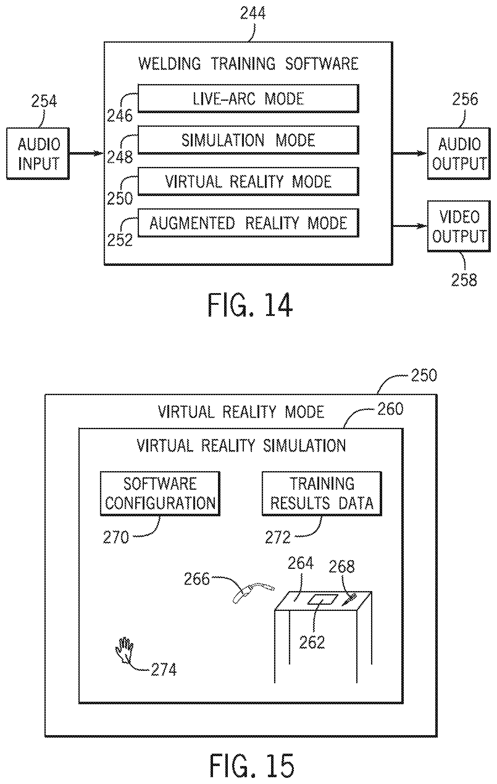
D00013

D00014
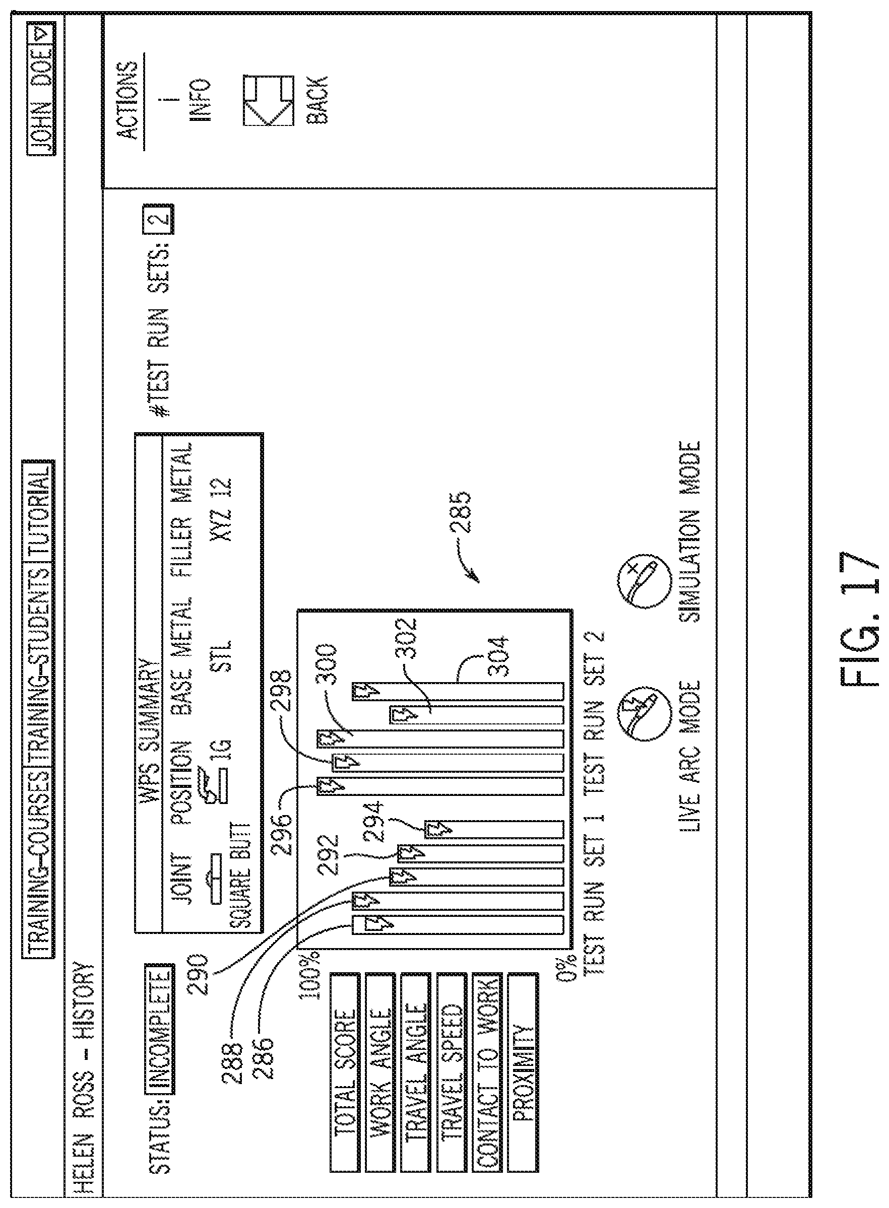
D00015

D00016
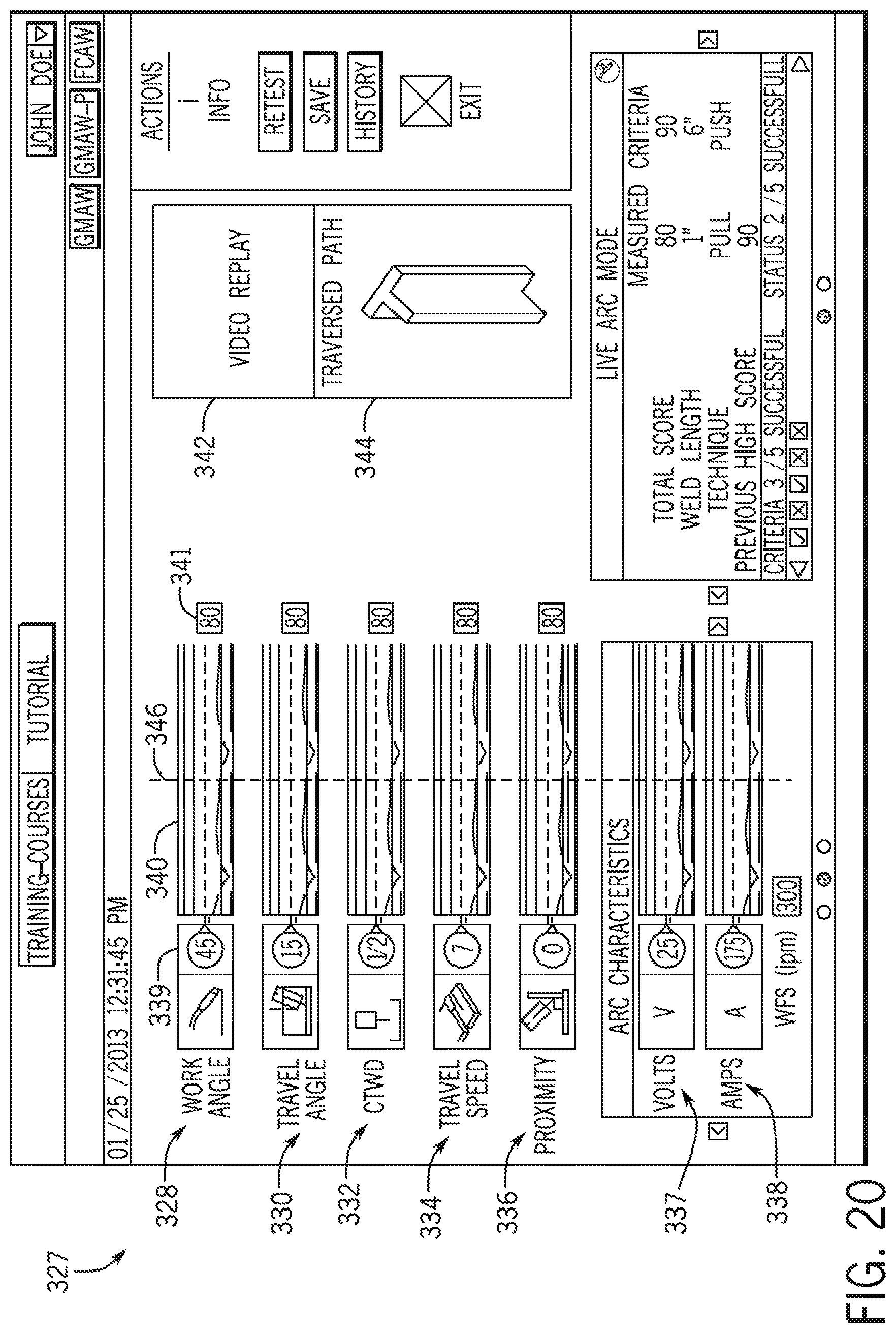
D00017

D00018
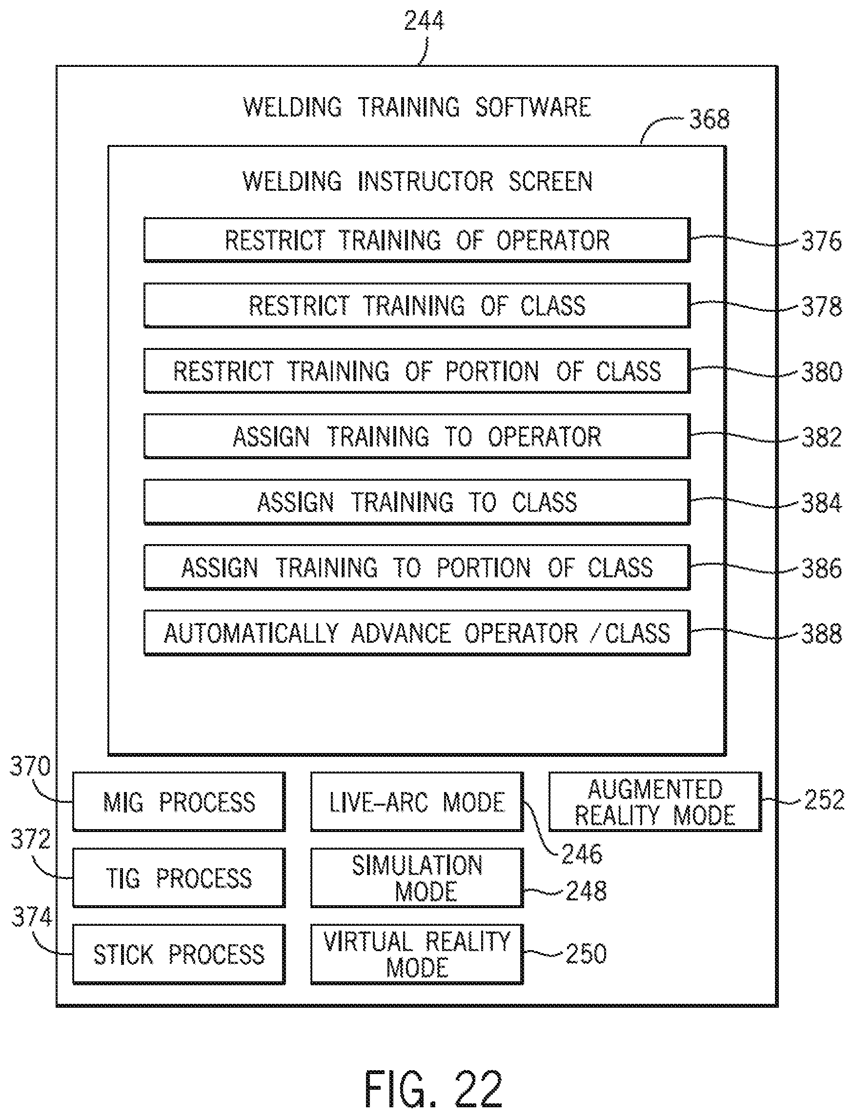
D00019
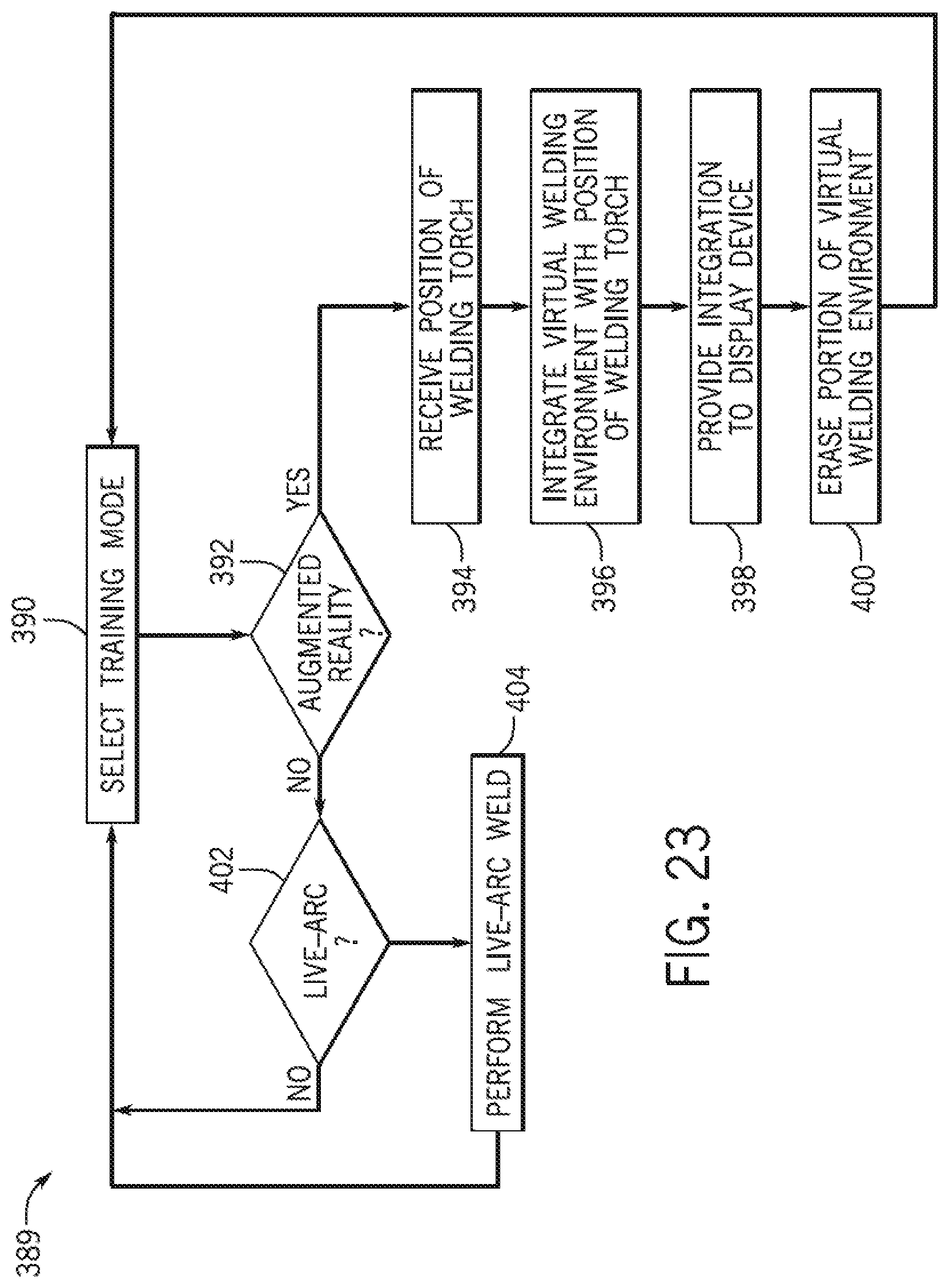
D00020
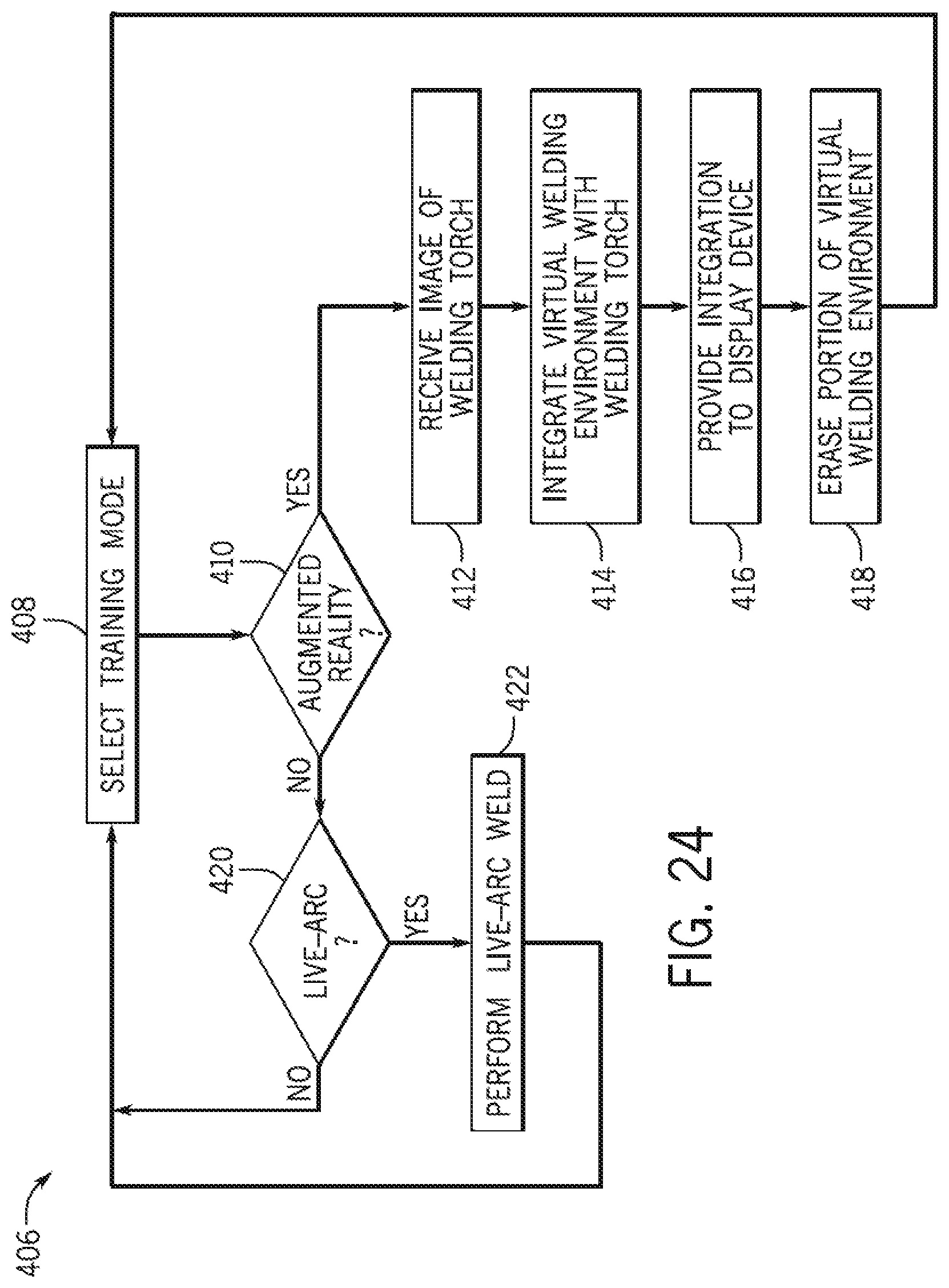
D00021
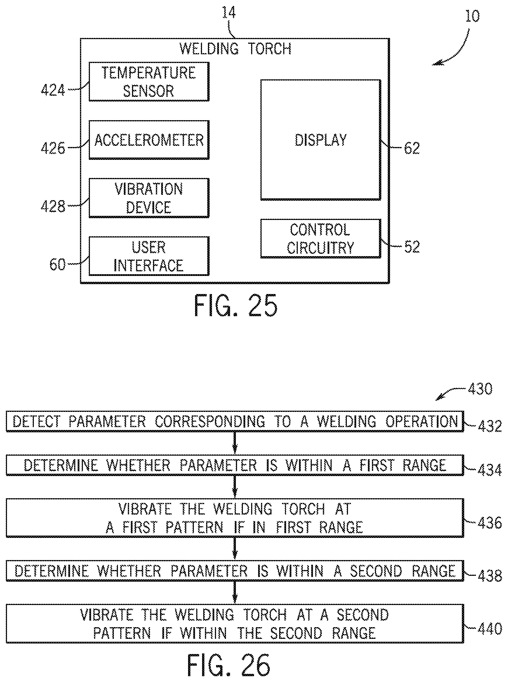
D00022
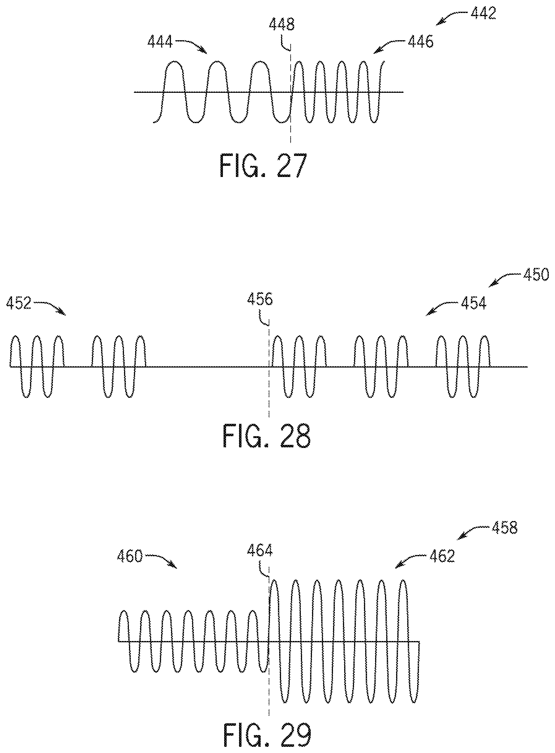
D00023
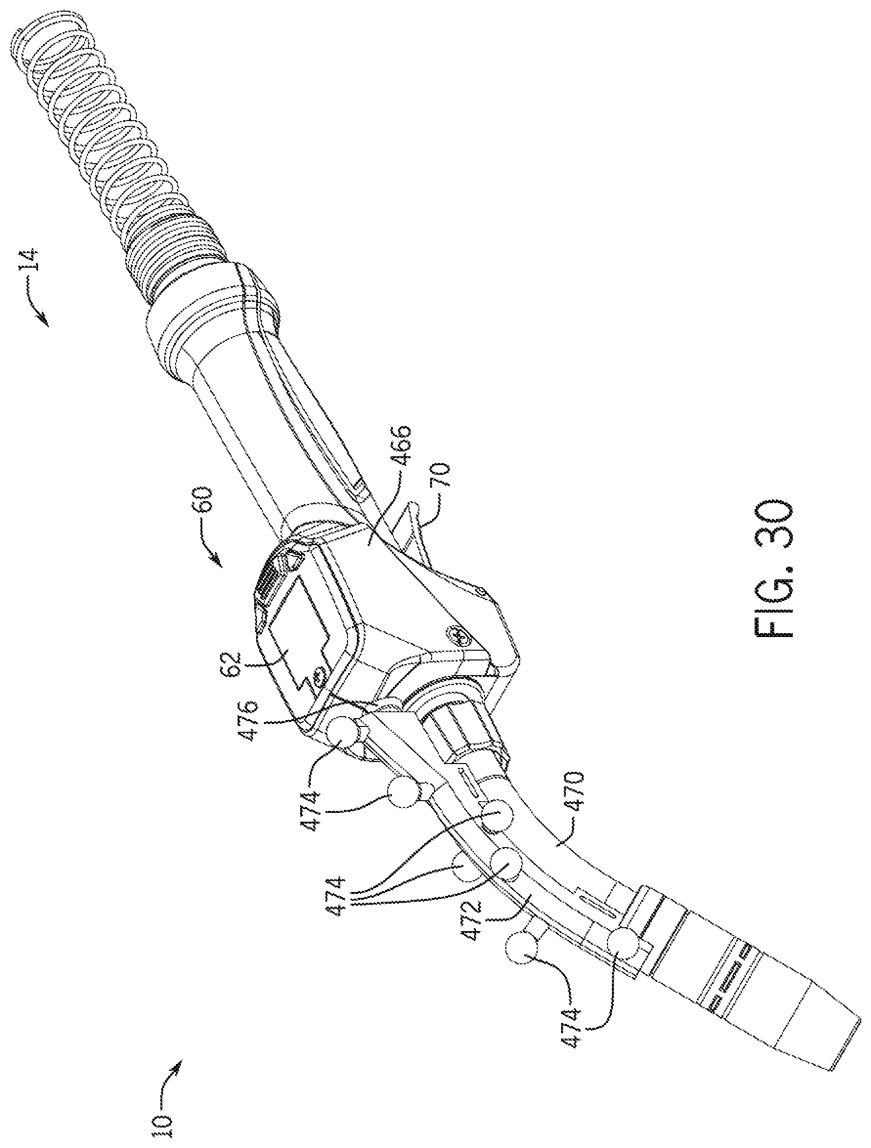
D00024

D00025
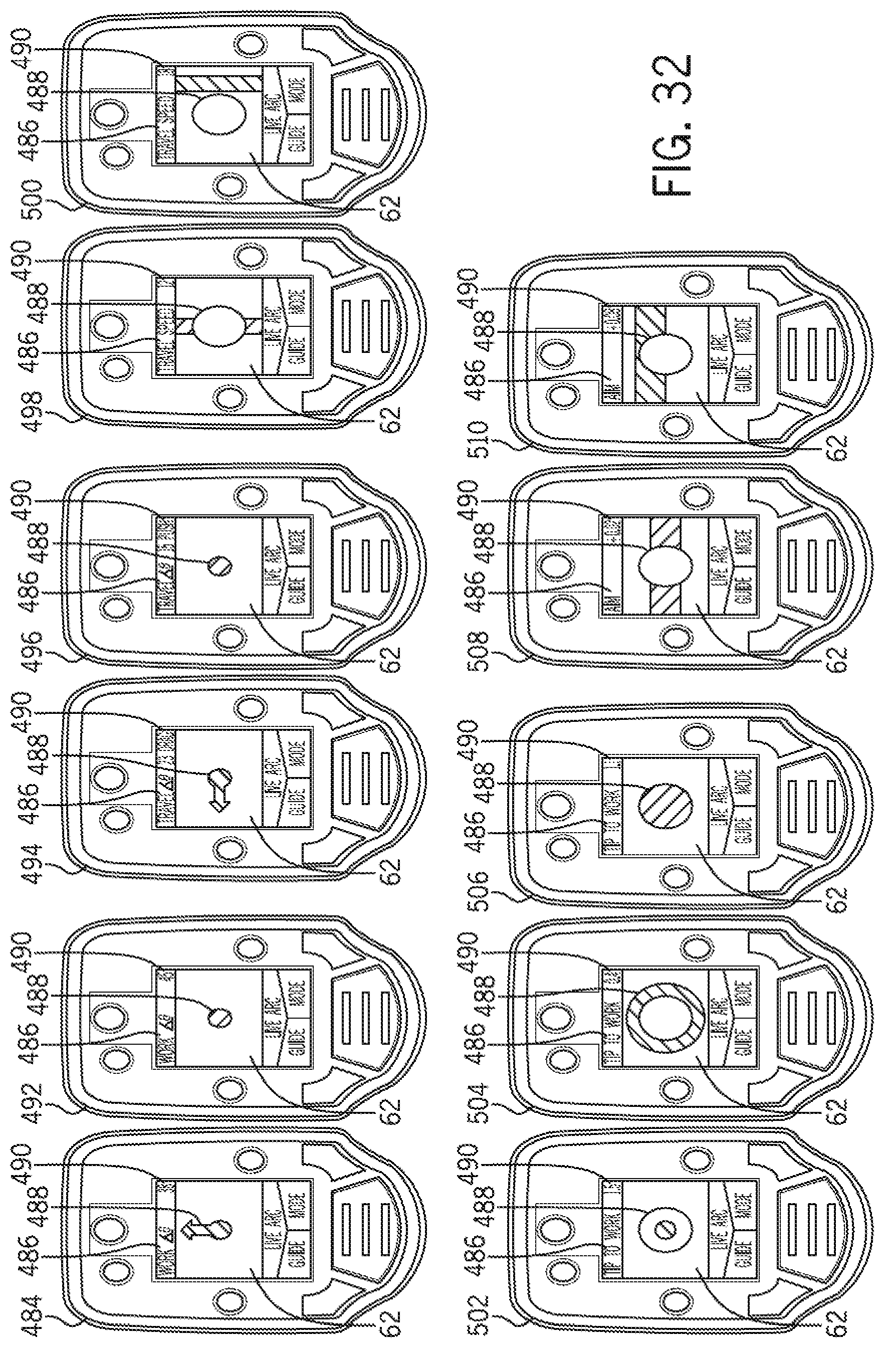
D00026
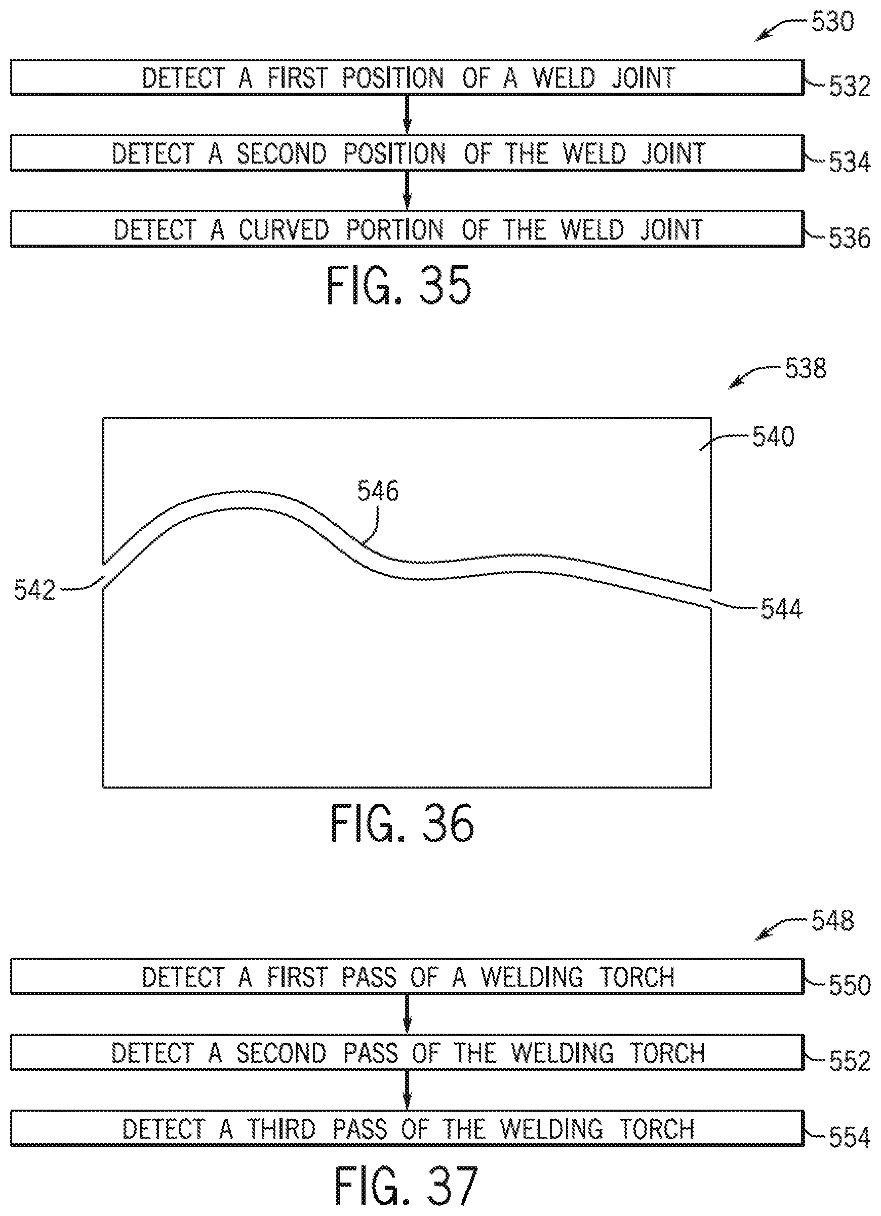
D00027
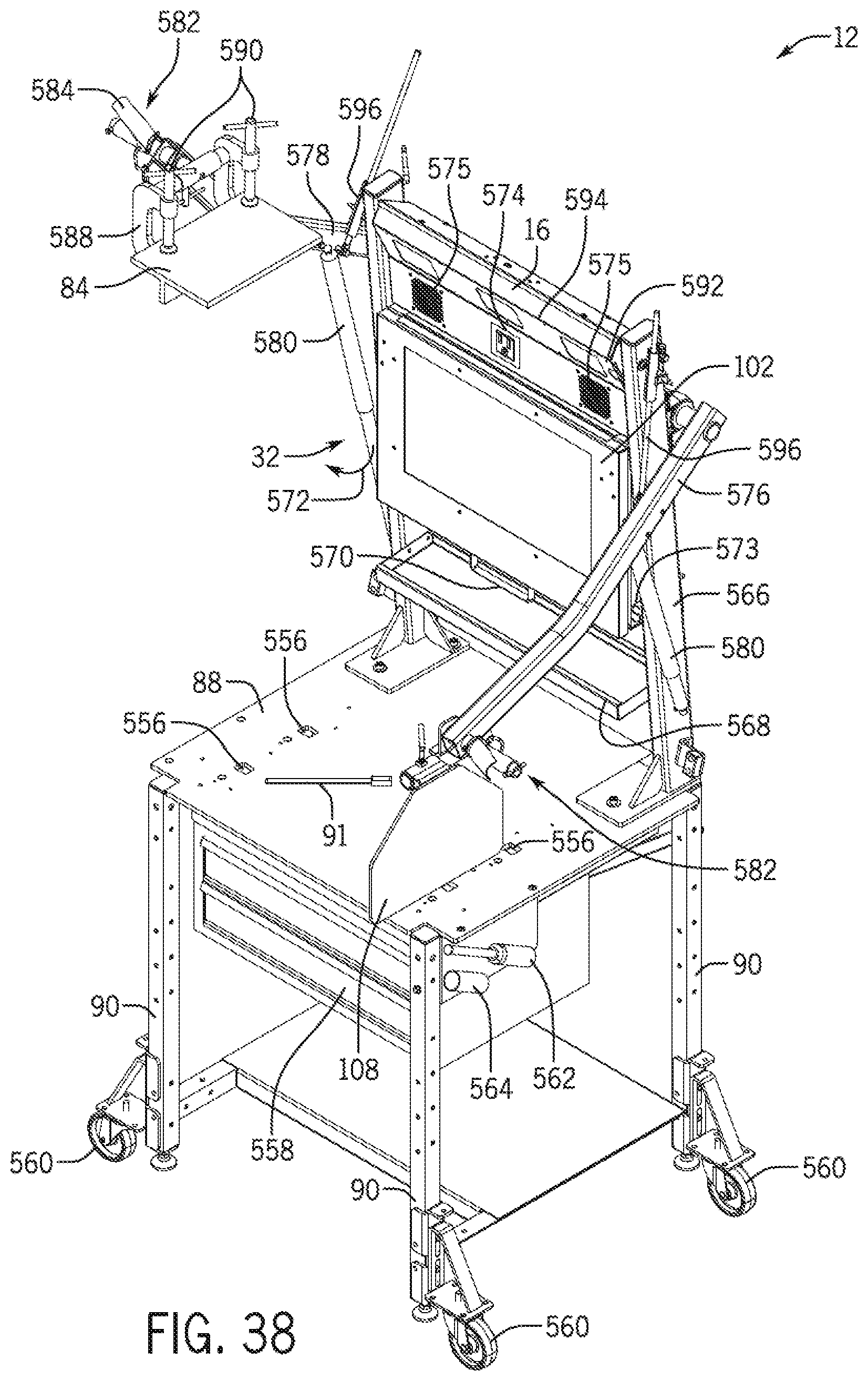
D00028

D00029
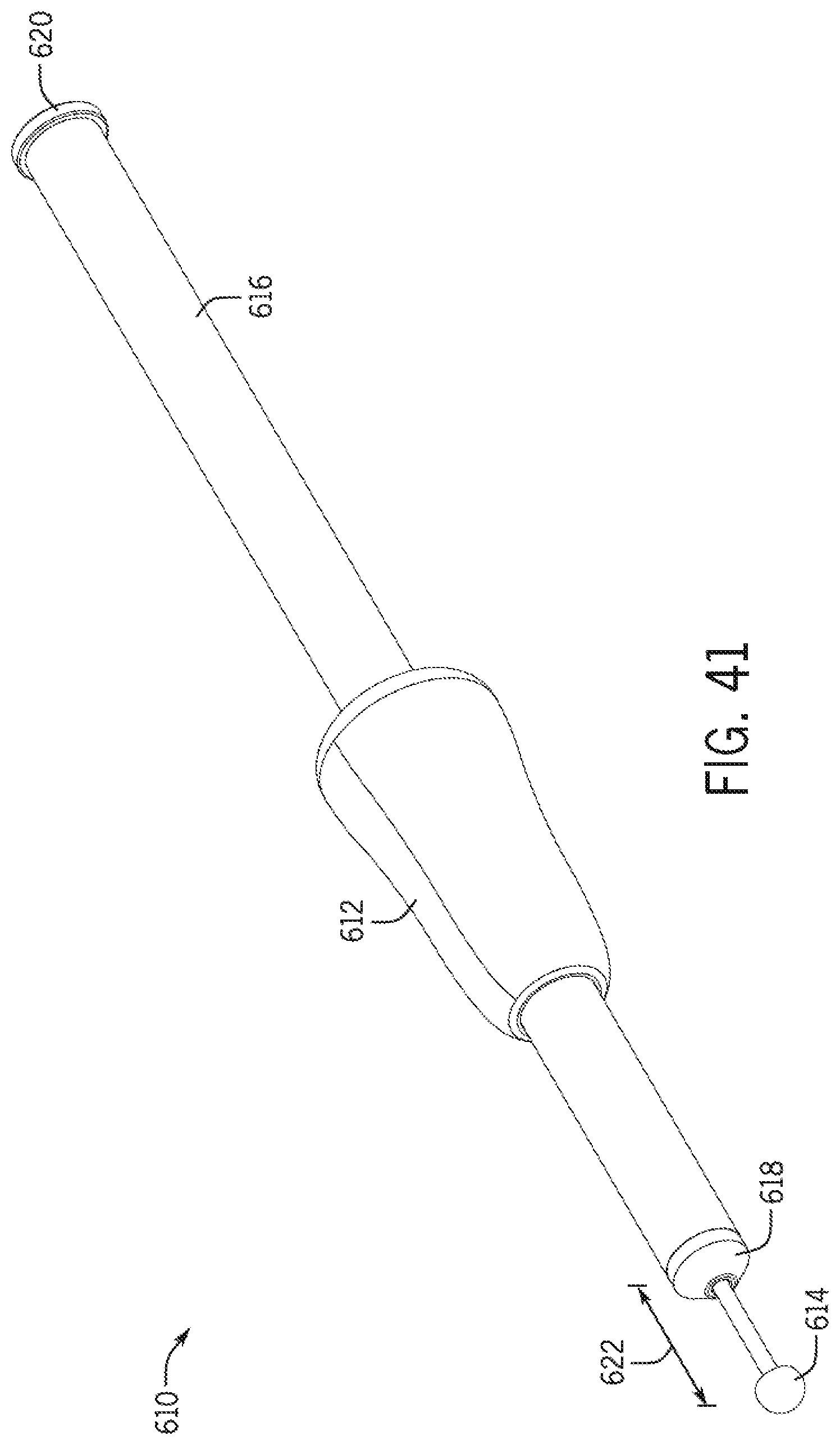
D00030
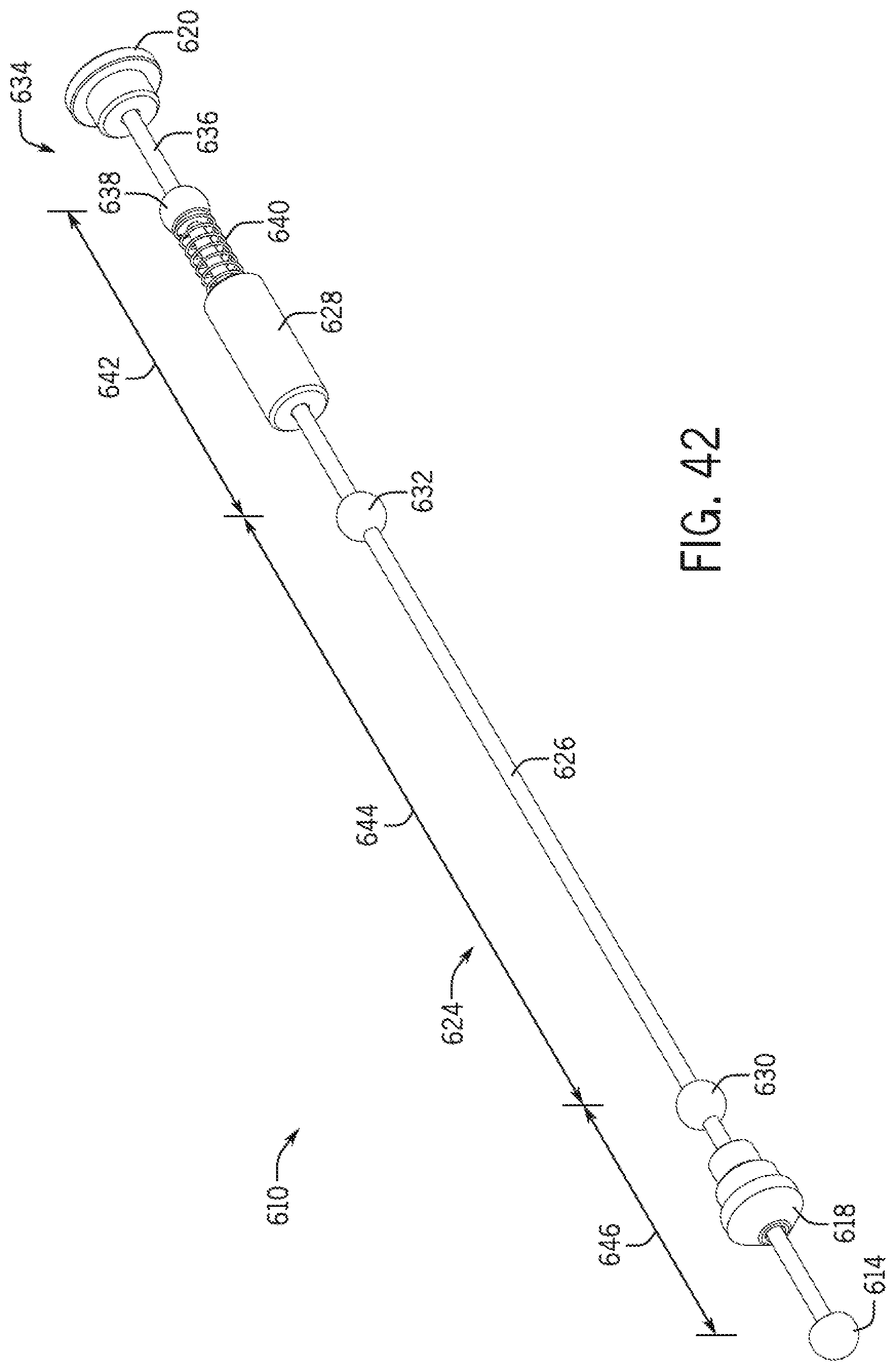
D00031
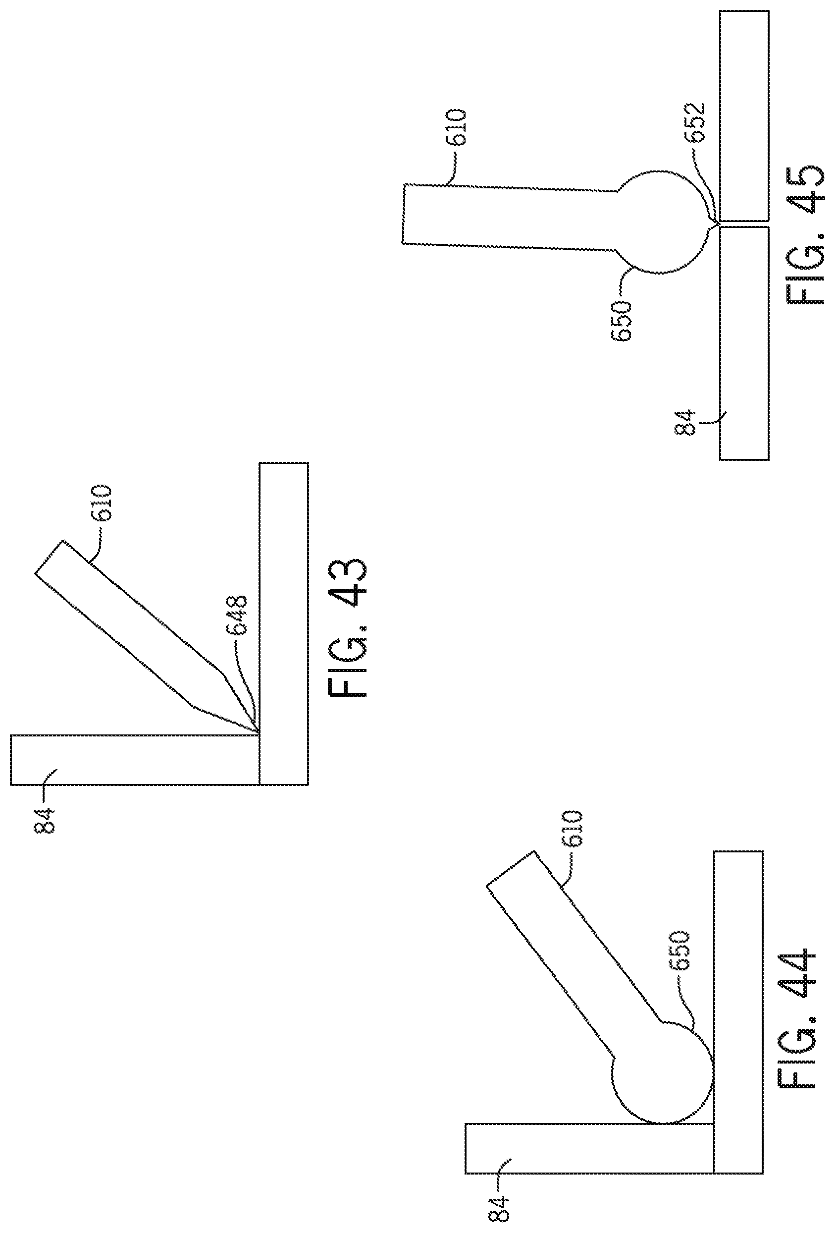
D00032
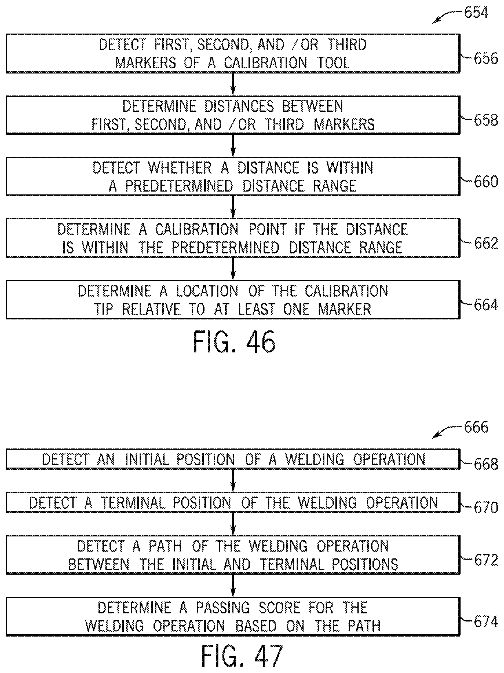
D00033
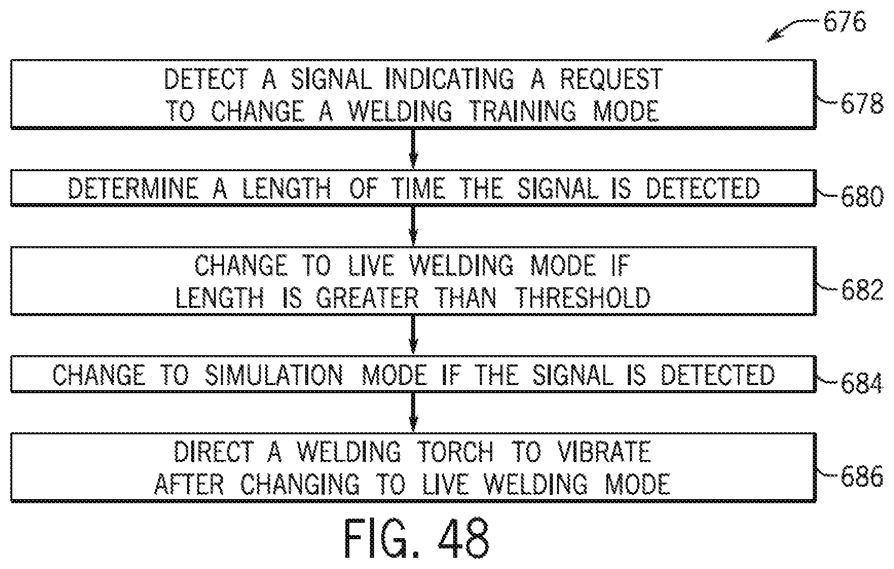
D00034

D00035

D00036

D00037
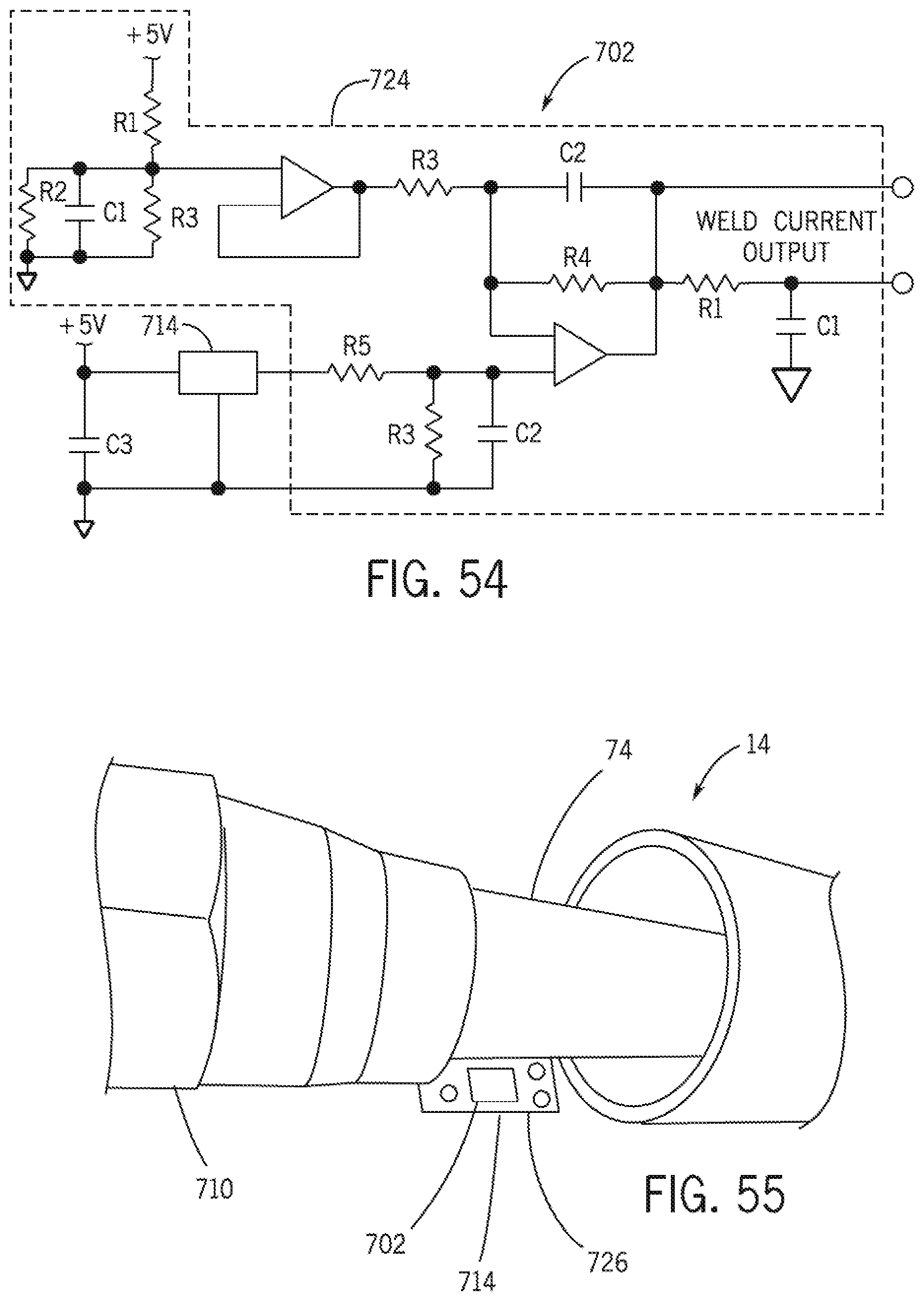
D00038

XML
uspto.report is an independent third-party trademark research tool that is not affiliated, endorsed, or sponsored by the United States Patent and Trademark Office (USPTO) or any other governmental organization. The information provided by uspto.report is based on publicly available data at the time of writing and is intended for informational purposes only.
While we strive to provide accurate and up-to-date information, we do not guarantee the accuracy, completeness, reliability, or suitability of the information displayed on this site. The use of this site is at your own risk. Any reliance you place on such information is therefore strictly at your own risk.
All official trademark data, including owner information, should be verified by visiting the official USPTO website at www.uspto.gov. This site is not intended to replace professional legal advice and should not be used as a substitute for consulting with a legal professional who is knowledgeable about trademark law.