Ultrasonically Assisted Self-Piercing Riveting
Sun; Xin ; et al.
U.S. patent application number 16/585754 was filed with the patent office on 2020-04-02 for ultrasonically assisted self-piercing riveting. The applicant listed for this patent is UT-Battelle, LLC. Invention is credited to Jian Chen, Richard W. Davies, Zhili Feng, Xiaohua Hu, Hui Huang, Xin Sun.
| Application Number | 20200101519 16/585754 |
| Document ID | / |
| Family ID | 69947078 |
| Filed Date | 2020-04-02 |


| United States Patent Application | 20200101519 |
| Kind Code | A1 |
| Sun; Xin ; et al. | April 2, 2020 |
Ultrasonically Assisted Self-Piercing Riveting
Abstract
A method for installing a self-piercing rivet by introducing acoustic (ultrasonic) vibrational energy is provided. The method includes positioning multiple workpieces between a blank holder and a die, applying ultrasonic vibrations to locally soften the workpieces and driving, using a press tool, the self-piercing rivet into the workpieces, causing the self-piercing rivet to deform in a radially outward direction, thereby joining the workpieces together without thermal processing and without permanent alterations to the microstructure of the workpiece materials.
| Inventors: | Sun; Xin; (Knoxville, TN) ; Feng; Zhili; (Knoxville, TN) ; Chen; Jian; (Knoxville, TN) ; Huang; Hui; (Knoxville, TN) ; Hu; Xiaohua; (Knoxville, TN) ; Davies; Richard W.; (Knoxville, TN) | ||||||||||
| Applicant: |
|
||||||||||
|---|---|---|---|---|---|---|---|---|---|---|---|
| Family ID: | 69947078 | ||||||||||
| Appl. No.: | 16/585754 | ||||||||||
| Filed: | September 27, 2019 |
Related U.S. Patent Documents
| Application Number | Filing Date | Patent Number | ||
|---|---|---|---|---|
| 62738514 | Sep 28, 2018 | |||
| Current U.S. Class: | 1/1 |
| Current CPC Class: | B21J 15/025 20130101; B21J 15/12 20130101 |
| International Class: | B21J 15/02 20060101 B21J015/02; B21J 15/12 20060101 B21J015/12 |
Goverment Interests
STATEMENT REGARDING FEDERALLY SPONSORED RESEARCH AND DEVELOPMENT
[0002] This invention was made with government support under Contract No. DE-AC05-00OR22725 awarded by the U.S. Department of Energy. The government has certain rights in the invention.
Claims
1. A method for installing a self-piercing rivet, the method comprising: providing a self-piercing rivet tool including a punch and a die; positioning a plurality of workpieces between the punch and the die; applying ultrasonic vibrations to the plurality of workpieces between the punch and the die to locally soften a region of the plurality of workpieces; and driving, using the punch, a self-piercing rivet into the softened region of the plurality of workpieces, and causing the self-piercing rivet to deform in a radial-outward direction to join the plurality of workpieces together substantially at ambient temperature.
2. The method of claim 1 wherein the ultrasonic vibrations are indirectly applied to the plurality of workpieces through vibration of a portion of the self-piercing rivet tool.
3. The method of claim 1 further including clamping the plurality of workpieces between a blank holder and the die.
4. The method of claim 1 further including providing an ultrasonic transducer to apply the ultrasonic vibrations to at least one of the plurality of workpieces.
5. The method of claim 1 wherein applying ultrasonic vibrations imparts vibrations in a direction perpendicular to a surface of the plurality of workpieces.
6. The method of claim 1 wherein applying ultrasonic vibrations imparts vibrations in a direction parallel to a surface of the plurality of workpieces.
7. The method of claim 1 wherein applying ultrasonic vibrations imparts rotational vibrations about an axis that is normal to a surface of the plurality of workpieces.
8. The method of claim 1 wherein applying ultrasonic vibrations is performed prior to the step of driving the self-piercing rivet.
9. The method of claim 1 wherein applying ultrasonic vibrations is performed concurrently with the step of driving the self-piercing rivet.
10. The method of claim 1 wherein applying ultrasonic vibrations is performed prior to and concurrently with the step of driving the self-piercing rivet.
11. A self-piercing rivet tool comprising: a punch and a die which are operable to drive a self-piercing rivet into a plurality of workpieces positioned between the punch and the die, the self-piercing rivet having a hollow leg extending from a head, the die having a cavity; and an ultrasonic transducer operable to locally soften a region of the plurality of workpieces positioned between the punch and the die, wherein the hollow leg of the self-piercing rivet is deformed in a radial outward direction when driven into the plurality of workpieces in an axial direction to join the plurality of workpieces together.
12. The self-piercing rivet tool of claim 11 wherein the ultrasonic transducer is coupled to the plurality of workpieces through an ultrasonic horn.
13. The self-piercing rivet tool of claim 11 wherein the ultrasonic transducer causes the plurality of workpieces to oscillate in a direction perpendicular to the axial direction.
14. The self-piercing rivet tool of claim 11 wherein the ultrasonic transducer causes the plurality of workpieces to oscillate in a direction parallel to the axial direction.
15. The self-piercing rivet tool of claim 11 wherein the ultrasonic transducer imparts rotational oscillations in the plurality of workpieces about the axial direction.
16. A method for installing a self-piercing rivet, the method comprising: providing a self-piercing rivet tool including a punch, a blank holder, and a die; clamping a plurality of workpieces between the blank holder and the die, the plurality of workpieces including an upper sheet and a lower sheet; applying ultrasonic vibrations to the plurality of workpieces in the region between the blank holder and the die to locally soften the plurality of workpieces; and driving, using the punch, a self-piercing rivet into the softened region of the plurality of workpieces in an axial direction and causing the self-piercing rivet to deform outwardly in a radial direction to join the plurality of workpieces together.
17. The method of claim 16 wherein the ultrasonic vibrations are indirectly applied to the plurality of workpieces through vibration of a portion of the self-piercing rivet tool.
18. The method of claim 16 wherein applying ultrasonic vibrations imparts vibrations in a direction perpendicular to the axial direction.
19. The method of claim 16 wherein applying ultrasonic vibrations imparts vibrations in a direction parallel to the axial direction.
20. The method of claim 16 wherein applying ultrasonic vibrations imparts rotational vibrations about the axial direction.
Description
CROSS-REFERENCE TO RELATED APPLICATIONS
[0001] This application claims the benefit of U.S. Provisional Application 62/738,514, filed Sep. 28, 2018, the disclosure of which is incorporated by reference in its entirety.
FIELD OF THE INVENTION
[0003] The present invention relates to self-piercing riveting systems to connect a plurality of workpieces with one another.
BACKGROUND OF THE INVENTION
[0004] Self-piercing riveting (SPR) is a cold joining method in which a rivet 100 is driven by a press tool 102 towards a die 104 to join a top sheet 106 to a bottom sheet 108, shown in FIG. 1. SPR achieves joining by causing the rivet 100 to flare into the bottom sheet 108 mechanically, and without thermal input or processing, which might otherwise degrade the microstructure and properties of highly engineered structural materials such as high-strength aluminum and high-strength steel. For example, SPR is widely used in the automotive industry to join lightweight dissimilar materials such as aluminum alloy structures, aluminum-steel structures, and other mixed structures that are difficult to join by resistance spot welding, which would involve melting and solidification.
[0005] However, SPR is not well suited for joining materials with low ductility (e.g., magnesium alloys and 700 series aluminum alloys) or high strength materials (e.g. high strength alloys). For example, materials having a low ductility and high strength materials can rupture due to excessive deformations in riveting. Various thermally-assisted approaches have been attempted using laser heating, induction heating, and frictional heating to increase a material's ductility while reducing flow stress. Other joining methods such as friction stir welding, friction stir spot welding, friction bit joining, and ultrasonic welding also rely on significant heating and temperature increases in the bonded region to soften the workpiece (or base material) to enable bonding.
[0006] In addition to the additional energy associated with these thermal-based processes, the elevated temperature produced in these methods can permanently alter a material's microstructure, and hence degrade the mechanical strength and associated joint properties. Accordingly, there remains a continued need for an improved system in which two materials can be SPR-joined at room temperature, including materials with low ductility and high strength, optionally without the aid of existing thermal techniques.
SUMMARY OF THE INVENTION
[0007] A method for installing a self-piercing rivet by introducing acoustic (ultrasonic) vibrational energy is provided. The method includes positioning multiple workpieces between a blank holder and a die, applying ultrasonic vibrations to locally soften the workpieces and driving, using a press tool, the self-piercing rivet into the workpieces, causing the self-piercing rivet to deform in a radially outward direction, thereby joining the workpieces together without thermal processing and without permanent alterations to the microstructure of the workpiece materials.
[0008] Embodiments of the present invention include applying ultrasonic vibrations to the press tool, the blank holder, the die, and/or the workpiece(s) directly. For example, embodiments include a transducer to impart ultrasonic vibration on a punch, the transducer converting electrical energy to ultrasonic vibration at a desired frequency. High frequency ultrasonic vibrations are imparted during the riveting process until the two workpieces are clinched, with the amplitude of vibration optionally in the range of 2-100 micrometers (.mu.m), optionally 2-40 .mu.m, and the frequency of vibration greater than 20 kHz, optionally 20 to 80 kHz, further optionally 20 to 60 kHz.
[0009] In one embodiment, continuous ultrasonic vibrations are applied to the workpiece(s) for at least the length of time that the press tool drives the rivet into the workpiece(s). In other embodiments, continuous ultrasonic vibrations are applied to the workpiece(s) prior to the self-piercing rivet being driven by the press tool, for example when the workpiece stack is clamped between the blank holder and the die, but prior to the press tool driving the rivet. In still other embodiments, continuous ultrasonic vibrations are applied to the workpiece(s) at least prior to and while the rivet is driven by the press tool. The ultrasonic vibrations can be applied in the direction that the rivet is being driven, perpendicular to the direction that the rivet is being driven, or rotatively about an axis parallel to the direction that the rivet is being driven.
[0010] The use of ultrasonic vibrational energy softens the workpieces, while at generally room temperature, thereby decreasing the plastic flow stress of the workpiece material, including materials with high strength and low ductility. The present method retains the benefits of the SPR process, including the reduction of processing loads and the improvement of a material's plastic deformation capability. Different transducers and/or coupling devices are possible to apply different modes of vibration in which the direction of the ultrasonic vibration is in principle parallel to the surface of the workpieces, perpendicular to the surface of the workpieces, or cyclic with rotation about an axis that is perpendicular to the surface of the workpieces.
[0011] These and other features of the invention will be more fully understood and appreciated by reference to the description of the embodiments and the drawings.
[0012] Before the embodiments of the invention are explained in detail, it is to be understood that the invention is not limited to the details of operation or to the details of construction and the arrangement of the components set forth in the following description or illustrated in the drawings. The invention may be implemented in various other embodiments and of being practiced or being carried out in alternative ways not expressly disclosed herein. In addition, it is to be understood that the phraseology and terminology used herein are for the purpose of description and should not be regarded as limiting. The use of "including" and "comprising" and variations thereof is meant to encompass the items listed thereafter and equivalents thereof as well as additional items and equivalents thereof. Further, enumeration may be used in the description of various embodiments. Unless otherwise expressly stated, the use of enumeration should not be construed as limiting the invention to any specific order or number of components. Nor should the use of enumeration be construed as excluding from the scope of the invention any additional steps or components that might be combined with or into the enumerated steps or components.
BRIEF DESCRIPTION OF THE DRAWINGS
[0013] FIG. 1 is a schematic representation of a prior art self-piercing rivet for joining multiple workpieces.
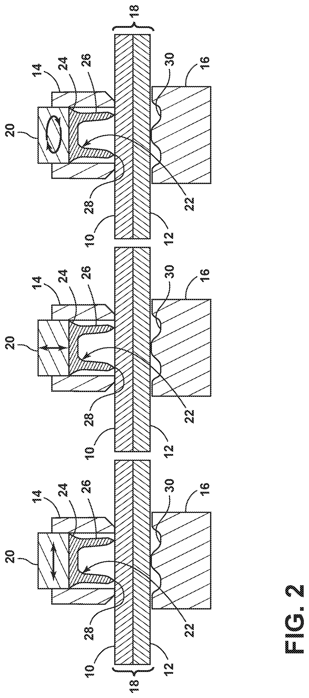
[0014] FIG. 2 is a schematic representation of ultrasonic vibrations imparted on a press tool for a self-piercing rivet.
[0015] FIGS. 3 is a schematic representation of ultrasonic vibrations imparted on a blank holder for a self-piercing rivet.
[0016] FIG. 4 is a schematic representation of ultrasonic vibrations imparted on a die for a self-piercing rivet.
[0017] FIG. 5 is a schematic representation of ultrasonic vibrations imparted on an upper workpiece for a self-piercing rivet.
[0018] FIG. 6 is a schematic representation of ultrasonic vibrations imparted on a lower workpiece for a self-piercing rivet.
[0019] FIG. 7 is a circuit diagram for a self-piercing rivet tool in accordance with an embodiment of the present invention.
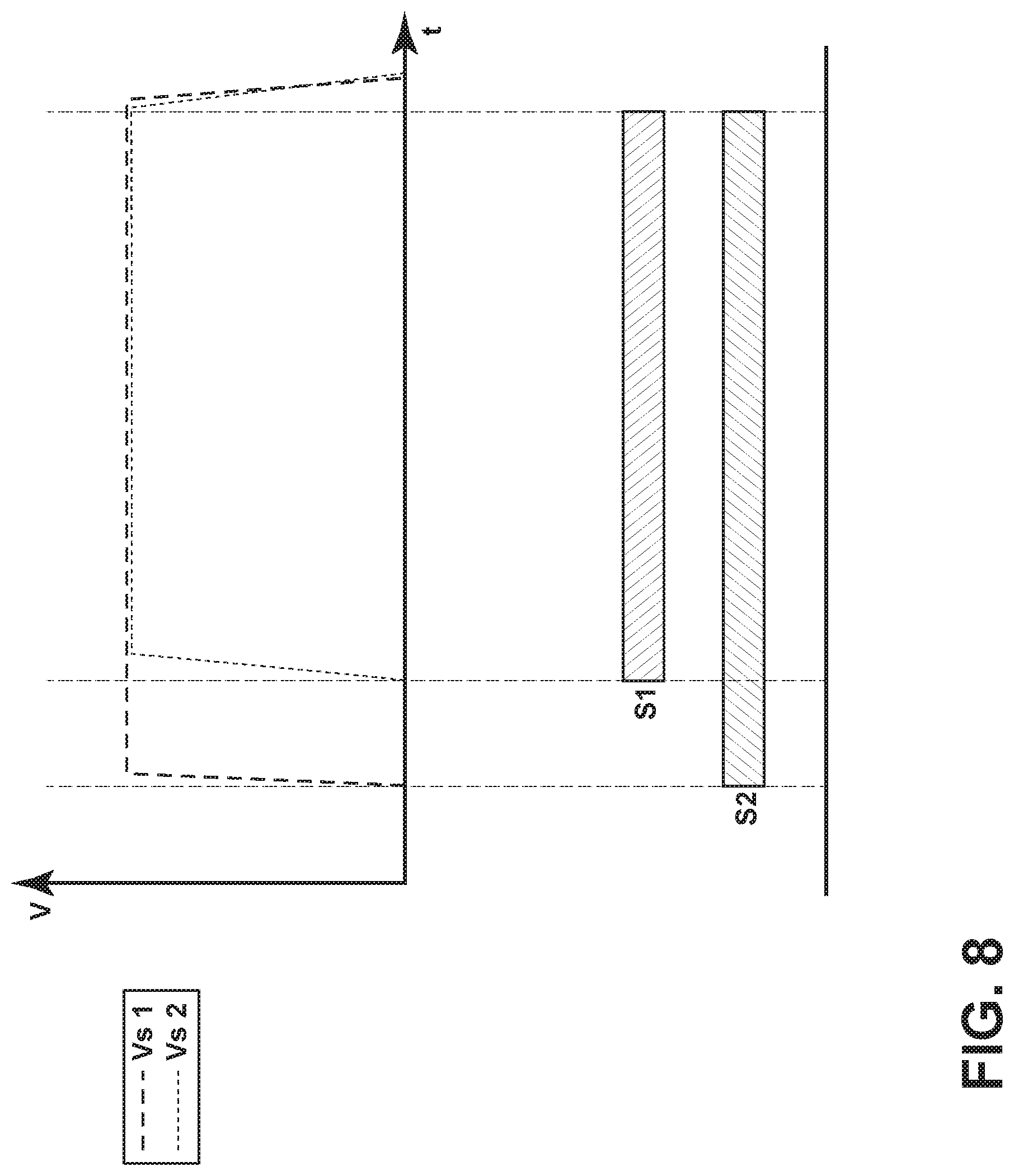
[0020] FIG. 8 is a first timing diagram for operation of an ultrasonic transducer and an electrically operated self-piercing rivet tool.
[0021] FIG. 9 is a second timing diagram for operation of an ultrasonic transducer and an electrically operated self-piercing rivet tool.
DETAILED DESCRIPTION OF THE CURRENT EMBODIMENTS
[0022] As discussed herein, the current embodiments generally relate to a method for installing a self-piercing rivet by introducing ultrasonic vibrational energy. The method generally includes positioning multiple workpieces between a blank holder and a die, applying ultrasonic vibrations to locally soften the workpieces and driving, using a press tool, the self-piercing rivet into the workpieces, causing the self-piercing rivet to deform in a radially outward direction, thereby joining the workpieces together without thermal processing and without permanent alterations to the microstructure of the workpiece materials. Each step is separately discussed below.
[0023] Referring to FIG. 2, positioning multiple workpieces between portions of a self-piercing rivet tool includes clamping an upper workpiece 10 and a lower workpiece 12 between a blank holder 14 and a die 16. The upper and lower workpieces 10, 12 form a stack 18, with the upper workpiece 10 being closest to the press tool 20 and the lower workpiece 12 being closest to the die 16. Though not shown, an optional material can be disposed between the upper workpiece 10 and the lower workpiece 12. A single self-piercing rivet 22 is secured within the blank holder 14. The self-piercing rivet 22 includes a widened head 24 and a partially hollow cylindrical stem 26 that terminates in a piercing edge 28. The length of the stem 26 is selected based on the thickness of the workpiece stack 18. When driven by the press tool 20, the partially hollow cylindrical stem 26 flares radially outwardly to join the upper workpiece 10 to the lower workpiece 12, but does not fully penetrate the workpiece stack 18. The die 16 defines an open die cavity 30 that faces the self-piercing rivet 22. The blank holder 14 and the die 16 provide a clamping force to retain the workpiece stack 18 in position.
[0024] Once positioned between portions of a self-piercing rivet tool, a transducer 40 (shown in FIG. 7) applies ultrasonic vibrations to the workpiece stack 18, directly or indirectly, to decrease the plastic flow stress of the workpiece material, including materials with high strength and low ductility. The transducer 40 can include a piezo-electric transducer operable to vibrate at ultrasonic frequencies, for example frequencies of greater than 20 kHz, further optionally between 20 kHz and 80 kHz, still further optionally between 20 kHz and 60 kHz, with the amplitude of vibration optionally in the range of 2-100 .mu.m, optionally 2-40 .mu.m. In one embodiment, the transducer 40 directs continuous ultrasonic vibrations to the workpiece stack 18 for at least the length of time that the press tool 20 drives the rivet 22 into the workpiece stack 18. In other embodiments, continuous ultrasonic vibrations are applied to the workpiece stack 18 prior to the self-piercing rivet 22 being driven by the press tool 20, for example when the workpiece stack 18 is clamped between the blank holder 14 and the die 16, but prior to the punch tool 20 driving the rivet 22. In still other embodiments, continuous ultrasonic vibrations are applied to the workpiece stack 18 at least prior to and while to the rivet 22 is driven by the press tool 20.
[0025] As shown in FIGS. 2-4, the ultrasonic vibrations can be applied in the direction that the rivet 22 is being driven, perpendicular to the direction that the rivet 22 is being driven, or rotatively about an axis parallel to the driven that the rivet 22 is being driven. FIG. 2 depicts ultrasonic vibrations as indirectly applied to the upper workpiece 10 through oscillation of the press tool 20 at ultrasonic frequencies. FIG. 3 depicts ultrasonic vibrations as indirectly applied to the upper workpiece 10 through oscillation of the blank holder 14, which avoids softening of the rivet 22. FIG. 4 depicts ultrasonic vibrations as indirectly applied to the lower workpiece 12 through oscillation of the die 16, which also avoids softening of the rivet 22. As the self-piercing rivet 22 is driven into the upper workpiece 10, the ultrasonic vibrations propagate to the upper or lower workpiece 10, 12 to locally soften these materials in the region directly between the rivet 22 and the die 16. During insertion, the cylindrical stem 26 deforms in a radially outward direction, but being inserted without full penetration of the workpiece stack 18.
[0026] As shown in FIGS. 5-6, the self-piercing rivet tool can include an ultrasonic horn 42 that is coupled to the transducer 40, transmitting ultrasonic vibrations parallel to its longitudinal axis, perpendicular to its longitudinal axis, or rotatively about its longitudinal axis. The longitudinal axis of the horn 42 can be oriented at an acute angle relative to the workpiece, for example an angle of between 30.degree. and 60.degree., further optionally about 45.degree.. The ultrasonic horn 42 includes a tapered geometry to augment the amplitude of the transducer 40. Optional geometries include a conical geometry, an exponential geometry, a stepped geometry, and combinations of the foregoing. At its tapered end, the horn 42 defines a contact surface for abutting one of the upper and lower workpieces 10, 12 of the workpiece stack 18. As shown in FIG. 5, for example, the horn 42 defines a contact surface for the upper workpiece 10 adjacent the blank holder 14. As alternatively shown in FIG. 6, for example, the horn 42 defines a contact surface for the lower workpiece 12 adjacent the die 16. The horn 42 (and transducer 40) are optionally biased toward the workpiece stack 18, such that the ultrasonic vibrations propagate from the transducer 40, through the ultrasonic horn 42 and into the workpiece stack 18 for reducing the plastic flow stress of the workpiece stack 18.
[0027] Referring now to FIG. 7, a circuit diagram for an electrically operated SPR tool in accordance with one embodiment is illustrated. The self-piercing rivet tool includes a controller 50 for controlling a supply voltage to a press tool 52 through operation of a first switch S 1. When activated, the first switch 51 closes a relay 54, which causes operation of the press tool 52 in the direction of a die. The controller 50 is also electrically coupled to a transducer 40 through a second switch S2 for imparting ultrasonic vibrations to a workpiece stack while clamped between a blank holder and a die. When activated, the second switch S2 couples the transducer 40 to a DC voltage (Vcc), which cause the transducer 40, for example a piezo-electric transducer, to vibrate at ultrasonic frequencies, for example frequencies of at least 20 kHz. In some embodiments, the second switch S2 is activated (in response to a command to initiate SPR) a predetermined period prior to activation of the first switch 51, such that the transducer 40 directs continuous ultrasonic vibrations to the workpiece stack prior to, and optionally during, activation of the first switch 51, shown in the timing diagram of FIG. 8. In other embodiments, the first switch 51 and the second switch S2 are activated simultaneously, such that the transducer 40 directs continuous ultrasonic vibrations to the workpiece stack only for the length of time that the press tool 52 drives the rivet into the workpiece stack, shown in the timing diagram of FIG. 9. In other embodiments the self-piercing rivet tool is pneumatically driven. The rivet tool may additionally be operated to remove self-piercing rivets with a die specifically for that purpose. During and/or prior to removal, the transducer can reduce the plastic flow stress of the workpiece material prior substantially as set forth above when installing a self-piercing rivet.
[0028] To reiterate, embodiments of the present invention include the application of ultrasonic energy to soften workpieces to facilitate self-pierce riveting, either by a transducer imposing ultrasonic vibration to the rivet tool (e.g., die, blank holder, punch) or directly to the workpiece(s). In some embodiments, high frequency ultrasonic vibration is introduced during the riveting process until the two workpieces are clinched. Different transducers and/or coupling devices are possible to apply different modes of vibration in which the direction of the ultrasonic vibration is in principle parallel to the surface of the workpieces, perpendicular to the surface of the workpieces, or cyclic with rotation about an axis that is perpendicular to the surface of the workpieces. The various modes of vibration can be combined for a given application to maximize the benefits of acoustic softening in self-piercing riveting operations.
[0029] The above description is that of current embodiments of the invention. Various alterations and changes can be made without departing from the spirit and broader aspects of the invention as defined in the appended claims, which are to be interpreted in accordance with the principles of patent law including the doctrine of equivalents. This disclosure is presented for illustrative purposes and should not be interpreted as an exhaustive description of all embodiments of the invention or to limit the scope of the claims to the specific elements illustrated or described in connection with these embodiments. For example, and without limitation, any individual element(s) of the described invention may be replaced by alternative elements that provide substantially similar functionality or otherwise provide adequate operation. This includes, for example, presently known alternative elements, such as those that might be currently known to one skilled in the art, and alternative elements that may be developed in the future, such as those that one skilled in the art might, upon development, recognize as an alternative. Further, the disclosed embodiments include a plurality of features that are described in concert and that might cooperatively provide a collection of benefits. The present invention is not limited to only those embodiments that include all of these features or that provide all of the stated benefits, except to the extent otherwise expressly set forth in the issued claims. Any reference to claim elements in the singular, for example, using the articles "a," "an," "the" or "said," is not to be construed as limiting the element to the singular.
* * * * *
D00000
D00001
D00002
D00003
D00004
D00005
D00006
D00007
D00008
D00009
XML
uspto.report is an independent third-party trademark research tool that is not affiliated, endorsed, or sponsored by the United States Patent and Trademark Office (USPTO) or any other governmental organization. The information provided by uspto.report is based on publicly available data at the time of writing and is intended for informational purposes only.
While we strive to provide accurate and up-to-date information, we do not guarantee the accuracy, completeness, reliability, or suitability of the information displayed on this site. The use of this site is at your own risk. Any reliance you place on such information is therefore strictly at your own risk.
All official trademark data, including owner information, should be verified by visiting the official USPTO website at www.uspto.gov. This site is not intended to replace professional legal advice and should not be used as a substitute for consulting with a legal professional who is knowledgeable about trademark law.