Toy Vehicle With Adjustable Chassis
Dunham; Steve ; et al.
U.S. patent application number 16/145549 was filed with the patent office on 2020-04-02 for toy vehicle with adjustable chassis. The applicant listed for this patent is Mattel, Inc.. Invention is credited to Steve Dunham, Timothy Rettberg, Brendon Vetuskey, Kelvin Xian.
| Application Number | 20200101394 16/145549 |
| Document ID | / |
| Family ID | 69944991 |
| Filed Date | 2020-04-02 |


| United States Patent Application | 20200101394 |
| Kind Code | A1 |
| Dunham; Steve ; et al. | April 2, 2020 |
TOY VEHICLE WITH ADJUSTABLE CHASSIS
Abstract
A toy vehicle with an adjustable chassis is disclosed. The toy vehicle comprises a chassis having a left frame rail and a right frame rail. Each of the left and right frame rails is moveable between a first position and a second position. One or more wheels are attached to each of the left and right frame rails and a vehicle body is mounted onto the chassis. Moving the left and right frame rails to their first positions results in the left and right frame rails moving toward each other and toward the vehicle body. Moving the left and right frame rails to their second positions results in the left and right frame rails moving away from each other and away from the vehicle body.
| Inventors: | Dunham; Steve; (Westchester, CA) ; Rettberg; Timothy; (Rancho Palos Verdes, CA) ; Vetuskey; Brendon; (Long Beach, CA) ; Xian; Kelvin; (Foshan, CN) | ||||||||||
| Applicant: |
|
||||||||||
|---|---|---|---|---|---|---|---|---|---|---|---|
| Family ID: | 69944991 | ||||||||||
| Appl. No.: | 16/145549 | ||||||||||
| Filed: | September 28, 2018 |
| Current U.S. Class: | 1/1 |
| Current CPC Class: | A63H 17/262 20130101 |
| International Class: | A63H 17/26 20060101 A63H017/26 |
Claims
1. A toy vehicle comprising: a chassis having a left frame rail and a right frame rail, each of the left and right frame rails being moveable between a first position and a second position; a front wheel and a rear wheel attached to each of the left and right frame rails; and a vehicle body mounted on top of the chassis; wherein moving the left and right frame rails to their first positions results in the left and right frame rails moving towards each other and upwards toward the vehicle body; and wherein moving the left and right frame rails to their second positions results in the left and right frame rails moving away from each other and downwards from the vehicle body.
2. The toy vehicle of claim 1, wherein the chassis further comprises a front portion and a rear portion, the front and rear portions each having slanted openings for guiding the left and right frame rails as the left and right frame rails move between their first positions and second positions.
3. The toy vehicle of claim 1, wherein the left and right frame rails are biased towards their first positions.
4. The toy vehicle of claim 1, further comprising one or more springs or elastic members biasing the left and right frame rails toward their first positions.
5. The toy vehicle of claim 1, further comprising an adjustment knob for controlling the movement of the left and right frame rails between their first positions and second positions.
6. The toy vehicle of claim 5, wherein turning the adjustment knob in a first direction moves the left and right frame rails to their first positions and turning the adjustment knob in a second direction moves the left and right frame rails to their second positions.
7. The toy vehicle of claim 5, further comprising a central bar positioned between the left frame rail and the right frame rail, wherein turning the adjustment knob causes the central bar to move the left and right frame rails between their first positions and second positions.
8. The toy vehicle of claim 7, wherein rotational movement of the adjustment knob is translated to linear movement of the central bar.
9. The toy vehicle of claim 1, wherein the front wheel and the rear wheel attached to each of the left and right frame rails freely rotate while the left and right frame rails are in their first positions and second positions.
10. A toy vehicle comprising: a chassis having a left frame rail and a right frame rail, the left and right frame rails being moveable between a first position and a second position; a front wheel and a rear wheel attached to each of the left and right frame rails; a vehicle body mounted onto of the chassis; and an adjustment mechanism for simultaneously moving the left and right frame rails between their first positions and second positions.
11. The toy vehicle of claim 10, wherein the chassis further comprises a front portion and a rear portion, the front and rear portions each having slanted openings for guiding the left and right frame rails as the left and right frame rails move between their first positions and second positions.
12. The toy vehicle of claim 10, wherein the left and right frame rails are biased towards their first positions.
13. The toy vehicle of claim 10, further comprising one or more springs or elastic members biasing the left and right frame rails toward their first positions.
14. The toy vehicle of claim 10, wherein the adjustment mechanism is a rotatable adjustment knob.
15. The toy vehicle of claim 14, wherein turning the adjustment knob in a first direction moves the left and right frame rails to their first positions and turning the adjustment knob in a second direction moves the left and right frame rails to their second positions.
16. The toy vehicle of claim 14, further comprising a central bar positioned between the left frame rail and the right frame rail, wherein turning the adjustment knob causes the central bar to move the left and right frame rails between their first positions and second positions.
17. The toy vehicle of claim 16, wherein rotational movement of the adjustment knob is translated to linear movement of the central bar.
18. The toy vehicle of claim 10, wherein the front wheel and the rear wheel attached to each of the left and right frame rails freely rotate while the left and right frame rails are in their first positions and second positions.
19. A toy vehicle comprising: a chassis having a front portion and a rear portion, the chassis further supporting a left frame rail and a right frame rail that are each moveable between a first position and a second position, the front and rear portions each having slanted openings for guiding the left and right frame rails as the left and right frame rails move between their first positions and second positions; a front wheel and a rear wheel attached to each of the left and right frame rails; and a vehicle body mounted onto the chassis; wherein moving the left and right frame rails to their first positions results in the left and right frame rails moving inwards toward a center of the chassis and upwards into the vehicle body; and wherein moving the left and right frame rails to their second positions results in the left and right frame rails moving away from the center of the chassis and downwards from the vehicle body.
20. The toy vehicle of claim 19 further comprising: an adjustment knob for controlling the movement of the left and right frame rails between their first positions and second positions; one or more springs or elastic members biasing the left and right frame rails toward their first positions; and a central bar positioned between the left frame rail and the right frame rail, wherein rotating the adjustment knob 90 degrees in a first direction results in the central bar moving the left and right frame rails to their second positions and turning the adjustment knob 90 degrees in a second direction opposite the first direction results in the central bar allowing the left and right frame rails to return to their first positions.
Description
FIELD OF THE INVENTION
[0001] The present invention relates generally to toy vehicles, and in particular, toy vehicles with an adjustable chassis.
BACKGROUND OF THE INVENTION
[0002] Toy cars and vehicles are popular toys for people of all ages. Generally, a typical toy vehicle comprises a vehicle body and a set of wheels attached directly to the vehicle body or to a chassis/frame forming part of the vehicle body. The positioning of the wheels in relation to the vehicle body plays an important part in the aesthetics and/or playability of the toy vehicle. Thus, to provide greater play value, it is desirable for a toy vehicle to have repositionable wheels, which allows a single vehicle to be displayed and played with in different configurations. Furthermore, it is desirable for the toy vehicle to have a built-in mechanism for easily adjusting the chassis and wheels on the toy vehicle.
SUMMARY OF THE INVENTION
[0003] A toy vehicle with an adjustable chassis is disclosed herein. According to one aspect of the present invention, the toy vehicle comprises a chassis having a left frame rail and a right frame rail. The left and right frame rails are moveable between a first position and a second position. A front wheel and a rear wheel are attached to each of the left and right frame rails and a vehicle body is mounted onto of the chassis. The toy vehicle also includes an adjustment mechanism for simultaneously moving the left and right frame rails between their first positions and second positions.
[0004] According to another aspect of the present invention, a toy vehicle is provided comprising a chassis having a left frame rail and a right frame rail. Each of the left and right frame rails is moveable between a first position and a second position. One or more wheels are attached to each of the left and right frame rails and a vehicle body is mounted on top of the chassis. In one of more embodiments, moving the left and right frame rails to their first positions results in the left and right frame rails moving towards each other and upwards toward the vehicle body. Moving the left and right frame rails to their second positions results in the left and right frame rails moving away from each other and downwards from the vehicle body. Preferably, the one or more wheels attached to each of the left and right frame rails freely rotate while the left and right frame rails are in their first positions and second positions.
[0005] The chassis of the toy vehicle further comprises a front portion and a rear portion. In one or more embodiments, the front and rear portions each have slanted openings for guiding the left and right frame rails as the left and right frame rails move between their first positions and second positions. In one instance, the left and right frame rails are biased towards their first positions. One or more springs or elastic members are used to bias the left and right frame rails toward their first positions.
[0006] In one or more embodiments, the toy vehicle has an adjustment knob for controlling the movement of the left and right frame rails between their first positions and second positions. In one instance, turning the adjustment knob in a first direction moves the left and right frame rails to their first positions and turning the adjustment knob in a second direction moves the left and right frame rails to their second positions. In some embodiments, the toy vehicle further comprises a central bar positioned between the left frame rail and right frame rail. Turning the adjustment knob causes the central bar to move the left and right frame rails between their first positions and second positions. In one instance, rotational movement of the adjustment knob is translated to linear movement of the central bar.
[0007] According to another aspect of the present invention, a toy vehicle is provided comprising a chassis having a front portion and a rear portion. The chassis supports a left frame rail and a right frame rail that are each moveable between a first position and a second position. A front wheel and a rear wheel are attached to each of the left and right frame rails and a vehicle body is mounted onto the chassis. The front and rear portions of the chassis each have slanted openings for guiding the left and right frame rails as the left and right frame rails move between their first positions and second positions. Moving the left and right frame rails to their first positions results in the left and right frame rails moving inwards toward a center of the chassis and upwards into the vehicle body. Moving the left and right frame rails to their second positions results in the left and right frame rails moving away from the center of the chassis and downwards from the vehicle body.
[0008] In one or more embodiments, the toy vehicle further comprises an adjustment knob for controlling the movement of the left and right frame rails between their first positions and second positions. One or more springs or elastic members bias the left and right frame rails toward their first positions. A central bar is also positioned between the left frame rail and right frame rail. In one instance, rotating the adjustment knob 90 degrees in a first direction results in the central bar moving the left and right frame rails to their second positions. Turning the adjustment knob 90 degrees in a second direction opposite the first direction results in the central bar allowing the left and right frame rails to return to their first positions.
[0009] Other objects, features and advantages of the present invention will become apparent to those skilled in the art from the following detailed description. It is to be understood, however, that the detailed description and specific examples, while indicating some embodiments of the invention, are given by way of illustration and not limitation. Many changes and modifications within the scope of the invention may be made without departing from the spirit thereof, and the present invention includes all such modifications.
BRIEF DESCRIPTION OF THE DRAWINGS
[0010] Referring now to the drawings in which like reference numbers represent corresponding parts throughout:
[0011] FIGS. 1A and 1B illustrate top views of a generalized representation of an adjustable chassis for a toy vehicle in a first configuration (FIG. 1A) and a second configuration (FIG. 1B), according to one embodiment of the invention;
[0012] FIGS. 2A and 2B illustrate front views of a toy vehicle in a first configuration (FIG. 2A) and a second configuration (FIG. 2B), according to another embodiment of the invention;
[0013] FIGS. 3A and 3B illustrate side views of a toy vehicle in a first configuration (FIG. 3A) and a second configuration (FIG. 3B), according to another embodiment of the invention;
[0014] FIGS. 4A and 4B illustrate bottom views of an adjustable chassis with frame rails in their first positions (FIG. 4A) and their second positions (FIG. 4B), according to the embodiment illustrated in FIGS. 3A and 3B;
[0015] FIGS. 5A and 5B illustrate top views of an adjustable chassis with a central bar in its first position (FIG. 5A) and its second position (FIG. 5B), according to the embodiment illustrated in FIGS. 3A and 3B;
[0016] FIG. 6 illustrates a bottom view of a toy vehicle, according to another embodiment of the invention;
[0017] FIG. 7 illustrates a bottom view of a toy vehicle, according to another embodiment of the invention; and
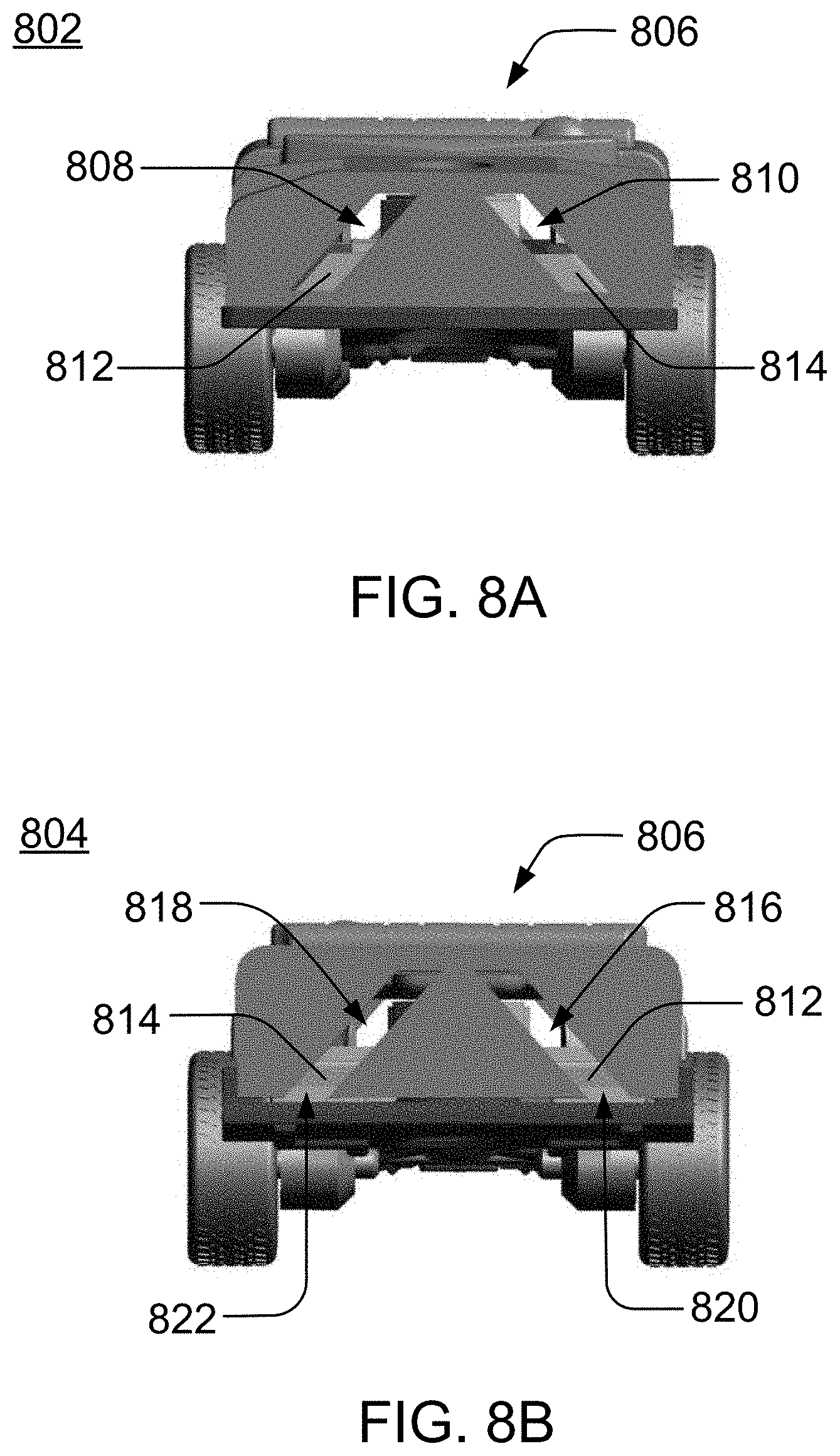
[0018] FIGS. 8A and 8B illustrate a front view (FIG. 8A) and rear view (FIG. 8B) of an adjustable chassis, according to the embodiment illustrated in FIG. 6.
DETAILED DESCRIPTION OF THE INVENTION
[0019] A toy vehicle according to the present invention includes an adjustable chassis with one or more movable frame rails. Depending on the positioning of the one or more frame rails, wheels attached to the one or more frame rails may be moved to different positions on the toy vehicle, thereby allowing the toy vehicle to be displayed and played with in different configurations.
[0020] Referring now to FIGS. 1A and 1B, a general embodiment of an adjustable vehicle frame or chassis 100 of a toy vehicle is shown. The chassis 100 is the main supporting structure of the toy vehicle to which other components, such as wheels 108 and a vehicle body (not shown), are attached. It is to be noted that though the toy vehicles are described and illustrated herein as having a separate vehicle body mounted on the chassis 100 (i.e., body-on-frame construction), the vehicle body may also be unified with the chassis 100 (i.e., unibody construction) in certain embodiments.
[0021] In a typical embodiment, chassis 100 includes a left frame rail 104 and a right frame rail 106 supported by a lower portion 102 of the chassis 100. The left and right frame rails 104, 106 can each be moved between a first position A (see FIG. 1A) and a second position B (see FIG. 1B). Moving the left and right frame rails 104, 106 in respective first directions (as indicated by the arrows in FIG. 1A) allows the left and right frame rails 104, 106 to shift to their second positions B. Conversely, moving the left and right frame rails 104, 106 in respective second directions (as indicated by the arrows in FIG. 1B) allows the left and right frame rails 104, 106 to shift back to their first positions A.
[0022] In a preferred embodiment, the left and right frame rails 104, 106 move together simultaneously when being shifted between their first and second positions. In other embodiments, the left and right frame rails 104, 106 are moved separately to their first and second positions. For example, the left frame rail 104 may be moved to its second position B while the right frame rail 106 remains in its first position A. Further, though two frame rail positions are described and illustrated herein (i.e., first position A and second position B), some embodiments of the adjustable chassis may have a different number of frame rail positions. In one instance, the left and right frame rails may each move incrementally through three or more frame rail positions. In other instances, due to a gradual/continuous transitional movement between the first and second positions, the left and right frame rails may each be positioned in the first or second position, as well as any position between the first and second positions.
[0023] Since wheels 108 are attached to the left and right frame rails 104, 106, the wheels 108 are also repositioned accordingly as the left and right frame rails 104, 106 move between their first and second positions. Thus, moving the left and right frame rails to their first or second positions transforms a toy vehicle to a respective first or second configuration with differently positioned wheels. Preferably, the wheels 108 can freely rotate in either vehicle configuration, irrespective of whether the left and right frame rails 104, 106 are in their first or second positions. This allows a user to play with the toy vehicle in multiple configurations.
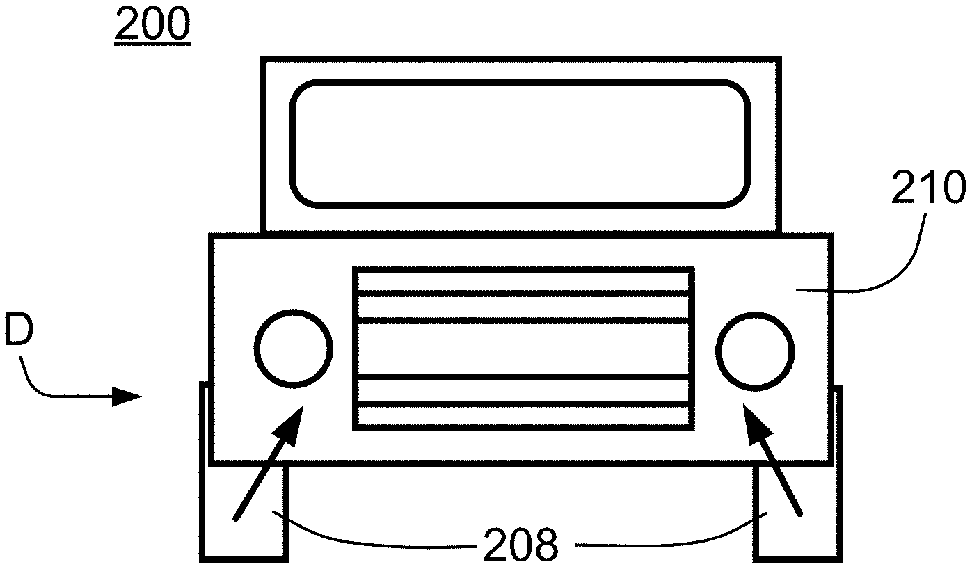
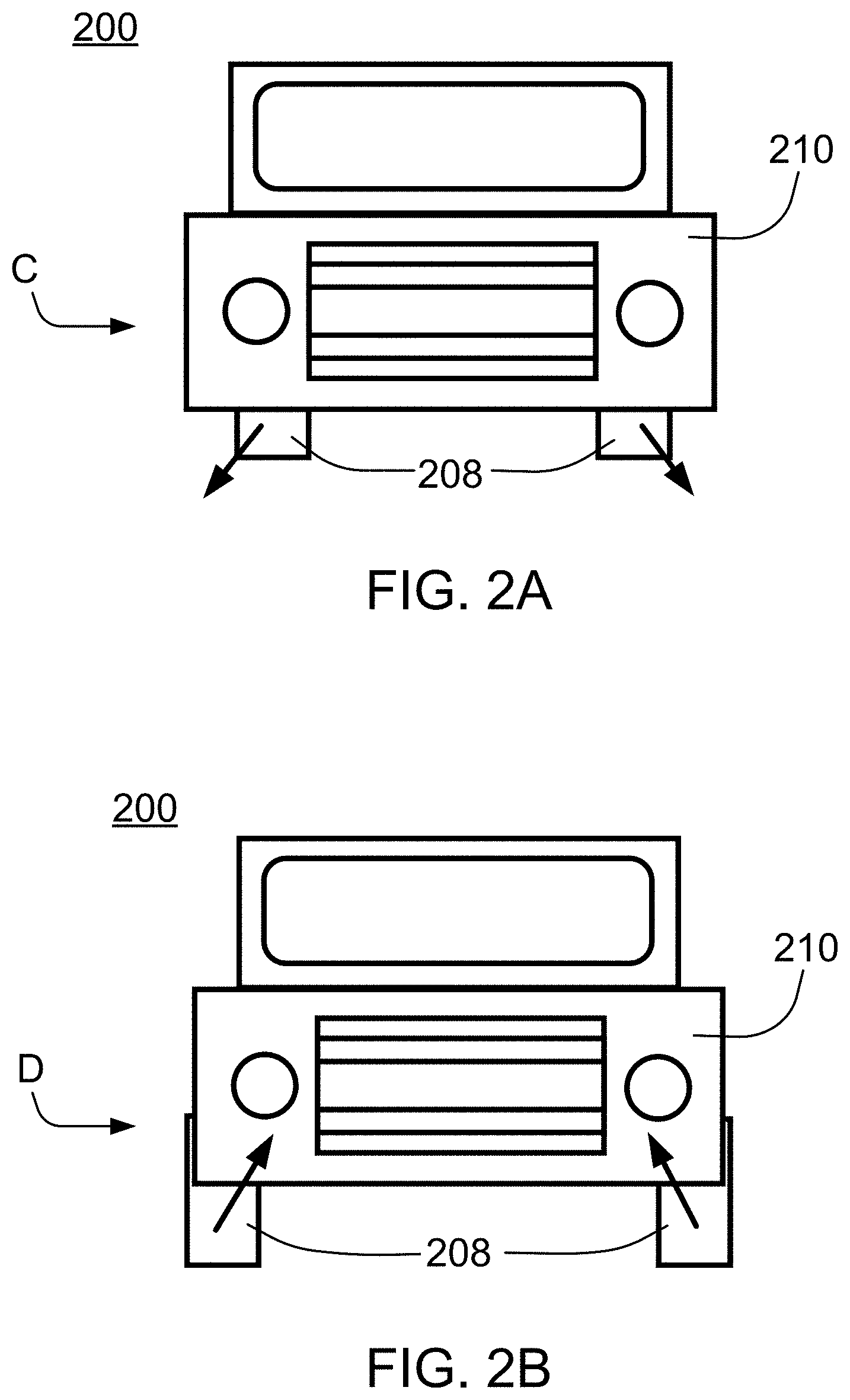
[0024] FIGS. 2A and 2B show an example of a toy vehicle 200 that has a first configuration C (see FIG. 2A) and second configuration D (see FIG. 2B). The toy vehicle 200 has a vehicle body 210 that is positioned over wheels 208 attached to an adjustable chassis (not shown). The vehicle body 210 can be of any shape or design as long as it has sufficient space inside to accommodate the chassis and/or the movement of the frame rails and wheels 208. In this illustrative embodiment, to transform the toy vehicle 200 from its first configuration C to its second configuration D, the chassis is adjusted such that it causes the wheels 208 to move at an angle both away from each other and downwards from the vehicle body 210. To transform the toy vehicle 200 from its second configuration D to its first configuration C, the chassis is adjusted such that it causes the wheels 208 to move at an angle both towards each other and upwards toward the vehicle body 210. In a preferred embodiment, the wheels 208 all move together simultaneously while the chassis is being adjusted. In other embodiments, one or more of the wheels 208 are moved separately while the chassis is being adjusted.
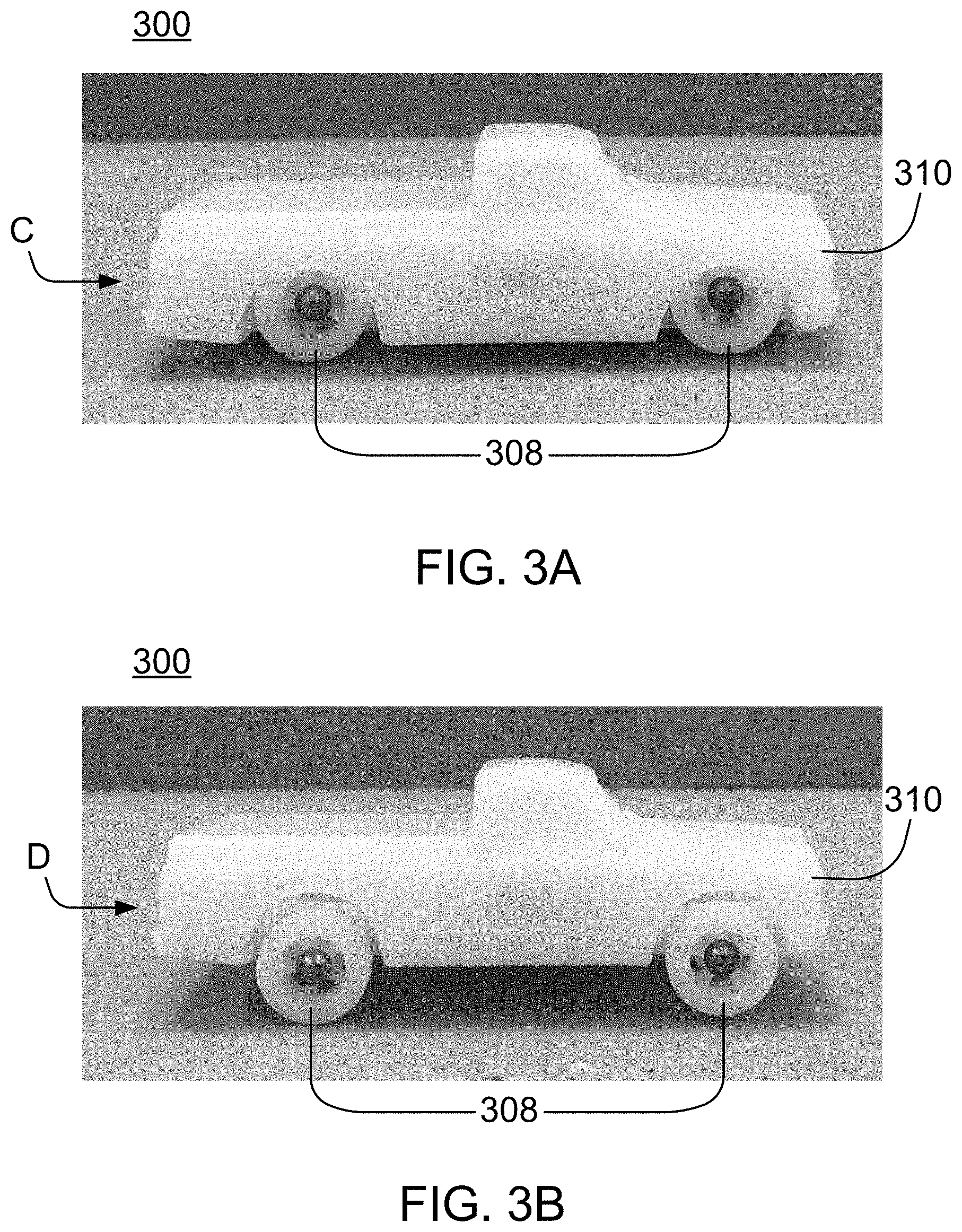
[0025] FIGS. 3A and 3B show side views of a toy vehicle 300 having a similar first configuration C (see FIG. 3A) and second configuration D (see FIG. 3B) as the toy vehicle 200 in FIGS. 2A and 2B. In its first configuration C, the positioning of the wheels 308 gives the toy vehicle 300 a lowered vehicle body 310 reminiscent of a lowrider car style when the toy vehicle 300 is placed on a support surface such as the floor, a track or a tabletop. In its second configuration D, the positioning of the wheels 308 gives the toy vehicle 300 a more "normal" car configuration where the vehicle body 310 is higher off the support surface. In addition to a difference in its appearance, changing the configuration of the toy vehicle 300 may also affect its racing characteristics. For example, the lower ride height or clearance of the toy vehicle 300 while it is in the low rider configuration C gives the toy vehicle 300 a low center of gravity. The toy vehicle 300 is thus less likely to topple or roll over when traveling at high speeds or performing sharp/abrupt turns. Transforming the toy vehicle 300 to the more "normal" configuration D gives the toy vehicle 300 a higher ground clearance that is helpful if the toy vehicle 300 is played on uneven terrain or travels through loops, ramps or obstacles.
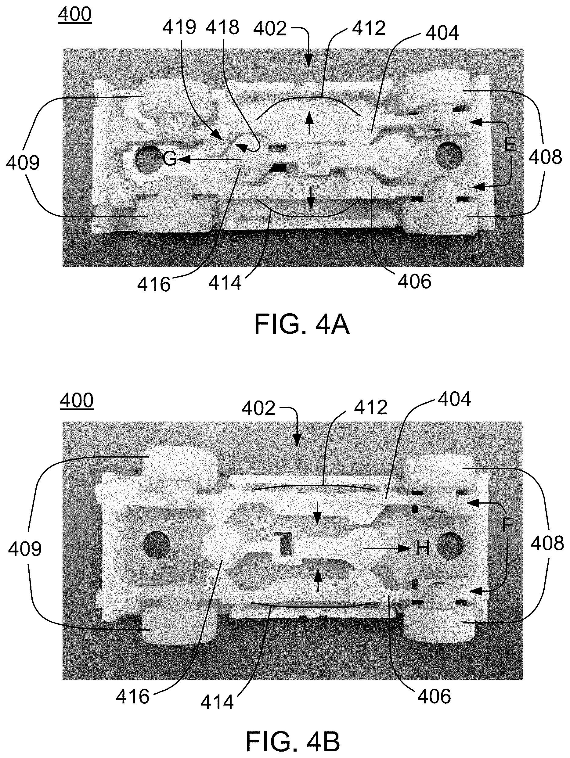
[0026] FIGS. 4A and 4B show an example of an adjustable chassis 400 viewed from the bottom of a toy vehicle similar to the toy vehicle 300 in FIGS. 3A and 3B. Specifically, FIGS. 4A and 4B show an upper portion 402 of the chassis 400. The lower portion of the chassis that supports the left frame rail 404 and a right frame rail 406 is not shown (see, e.g., FIGS. 5A and 5B for an example of the lower portion of a chassis). Front wheels 408 and rear wheels 409 are attached to the left frame rail 404 and right frame rail 406. Moving the left and right frame rails 404, 406 repositions the front and rear wheels 408, 409 accordingly.
[0027] The left and right frame rails 404, 406 can each be moved between a first or inner position E (see FIG. 4A) and a second or outer position F (see FIG. 4B). While the left and right frame rails 404, 406 are in their first positions E, shifting the left and right frame rails 404, 406 away from the center of the chassis 400 (as indicated by the arrows in FIG. 4A) and away from the vehicle body moves the left and right frame rails 404, 406 to their second positions F. Shifting the left and right frame rails 404, 406 toward the center of the chassis 402 (as indicated by the arrows in FIG. 4B) and toward the vehicle body moves the left and right frame rails 404, 406 back to their first positions E. Leaf springs 412, 414 further bias the left and right frame rails 404, 406 toward their first positions E.
[0028] The chassis 400 also includes a central bar 416 that is positioned between the left and right frame rails 404, 406. The central bar 416 has one or more angled cam surfaces 418 that contact one or more respective cam surfaces 419 on the left and right frame rails 404, 406. These cam surfaces are able to slide against each other as the central bar moves laterally back and forth. Moving the central bar backward in the direction G forces the left and right frame rails 404, 406 apart (i.e., to their second positions F). Moving the central bar forward in the direction H allows the leaf springs 412, 414 to push the left and right frame rails 404, 406 back toward the center of the chassis 402 (i.e., to their first positions E).
[0029] FIGS. 5A and 5B show an example of a lower portion 500 of a chassis. The lower portion 500 connects with the upper portion 402 of the chassis 400 (see, e.g., FIGS. 4A and 4B). The lower portion 500 of the chassis includes an adjustment knob 502 operatively connected to the central bar 416. In this illustrative embodiment, the adjustment knob 502 has a protrusion 504 that engages with an opening 506 on the central bar 416. The opening 506 is shaped such that movement of the protrusion 504 causes the central bar 416 to laterally move back and forth.
[0030] FIG. 5A shows a first position of the adjustment knob 502 and the central bar 416. As the adjustment knob 502 is turned counter-clockwise in the direction of arrow I, the central bar 416 moves back in the direction of arrow G, which results in the second position shown in FIG. 5B. In FIG. 5B, the adjustment knob 502 may then be turned clockwise in the direction of arrow J to move the central bar 416 forward in the direction of arrow H and return to the first position shown in FIG. 5A. As described earlier, moving the central bar 416 back or forth causes the left and right frame rails 404, 406 to move to their second positions B (see FIG. 4B) or return to their first positions A (see FIG. 4A), respectively. A stop is further included as part of the central bar 416, adjustment knob 502, and/or lower portion 500 of the chassis to prevent the adjustment knob 502 from being rotated more than 90 degrees in the counter-clockwise direction I or clockwise direction J.
[0031] FIG. 6 shows another example of a toy vehicle 600 including both an adjustable chassis 612 (the lower portion of the chassis 612 has been removed and is not shown) and a vehicle body 610. The toy vehicle 600 has an adjustment knob 602 with an extension 608 that a user can grasp to more easily rotate the adjustment knob 602. Turning the adjustment knob 602 clockwise in the direction of arrow J moves the central bar 616 forward in the direction of arrow H, which subsequently allows the left and right frame rails 604, 606 to move toward the center of the chassis 612 (as indicated by the arrows in FIG. 6) and toward the vehicle body 610. Though an adjustment knob 602 is described and illustrated herein, other adjustment mechanisms for moving the left and right frame rails 604, 606 may also be used. For example, the adjustment mechanism may utilize a switch, button or dial to adjust the positions of the left and right frame rails. Also, the left and right frame rails may be moved manually as described or mechanically through the use of an electric motor.
[0032] In other embodiments, the chassis does not include a central bar. FIG. 7 shows an example of a toy vehicle 700 where rotational movement of an adjustment knob 708 directly moves a left frame rail 704 and right frame rail 706. An elastic member 702, such as an elastic band, is coupled to the left frame rail 704 and right frame rail 706, thereby biasing the left and right frame rails 704, 706 to their first positions A. Each of the frame rails 704, 706 includes a pair of posts 703 as shown in FIG. 7. The elastic member 702 extends around all the posts 703, thereby pulling or biasing the frame rails 704, 706 toward each other.
[0033] The adjustment knob 708 is positioned between the left and right frame rails 704, 706 and has an extension 710 that a user can grasp to rotate the adjustment knob 708. Turning the adjustment knob 708 ninety degrees in either direction clockwise or counter-clockwise (as indicated by the arrow in FIG. 7) forces the left and right frame rails 704, 706 apart to their second positions. Continuing to turn the adjustment knob 708 ninety degrees in the same direction or in the opposite direction allows the elastic member 702 to pull the left and right frame rails 704, 7406 back toward the center of the toy vehicle (i.e., to their first positions).
[0034] FIGS. 8A and 8B show an example of a front portion 802 and rear portion 804 of an adjustable chassis 806. As shown in FIG. 8A, the front portion 802 has slanted openings 808, 810 for respectively guiding the left and right frame rails 812, 814 as they move between their first positions and second positions. Here, the left and right frame rails 812, 814 are depicted in their second positions. The slanted openings 808, 810 are angled such that the left and right frame rails 812, 814 simultaneously move both towards the center of the chassis 806 and upwards from a support surface/floor as the left and right frame rails 812, 814 move from their second positions to their first positions. Moving from their first positions to their second positions causes the left and right frame rails 812, 814 to simultaneously move both away from the center of the chassis 806 and downwards toward the support surface/floor.
[0035] As shown in FIG. 8B, the rear portion 804 also has slanted openings 816, 818 that are similarly angled, which allows the respective left and right frame rails 812, 814 to remain parallel to the supporting surface and each other as they move. The rear portion 804 further includes cutaways 820, 822 to facilitate the insertion of the left and right frame rails 812, 814 onto the chassis 806 during the manufacturing and/or assembly of the toy vehicle. In other embodiments, the chassis 806 may include openings of different shapes or angles to allow the left and right frame rails be repositioned in different positions on the toy vehicle.
[0036] Although the disclosed inventions are illustrated and described herein as embodied in one or more specific examples, it is nevertheless not intended to be limited to the details shown, since various modifications and structural changes may be made therein without departing from the scope of the inventions and within the scope and range of equivalents of the claims.
[0037] Moreover, it is to be understood that terms such as "left," "right," "top," "bottom," "front," "rear," "side," "height," "length," "width," "upper," "lower," "interior," "exterior," "inner," "outer" and the like as may be used herein, merely describe points or portions of reference and do not limit the present invention to any particular orientation or configuration. Further, the term "exemplary" may be used herein to describe an example or illustration. Any embodiment described herein as exemplary is not to be construed as a preferred or advantageous embodiment, but rather as one example or illustration of a possible embodiment of the invention.
[0038] Finally, various features from one of the embodiments may be incorporated into another of the embodiments. Accordingly, it is appropriate that the appended claims be construed broadly and in a manner consistent with the scope of the disclosure as set forth in the following claims.
* * * * *
D00000
D00001
D00002
D00003
D00004
D00005
D00006
D00007
XML
uspto.report is an independent third-party trademark research tool that is not affiliated, endorsed, or sponsored by the United States Patent and Trademark Office (USPTO) or any other governmental organization. The information provided by uspto.report is based on publicly available data at the time of writing and is intended for informational purposes only.
While we strive to provide accurate and up-to-date information, we do not guarantee the accuracy, completeness, reliability, or suitability of the information displayed on this site. The use of this site is at your own risk. Any reliance you place on such information is therefore strictly at your own risk.
All official trademark data, including owner information, should be verified by visiting the official USPTO website at www.uspto.gov. This site is not intended to replace professional legal advice and should not be used as a substitute for consulting with a legal professional who is knowledgeable about trademark law.