Small Core-diameter Graded-index Optical Fiber
XIAO; Wufeng ; et al.
U.S. patent application number 16/542506 was filed with the patent office on 2020-03-26 for small core-diameter graded-index optical fiber. The applicant listed for this patent is YANGTZE OPTICAL FIBRE AND CABLE JOINT STOCK LIMITED COMPANY. Invention is credited to Rong Huang, Haiying Wang, Runhan Wang, Tiejun Wang, Wufeng XIAO, Di Yang, Anlin Zhang.
| Application Number | 20200096697 16/542506 |
| Document ID | / |
| Family ID | 64909987 |
| Filed Date | 2020-03-26 |


| United States Patent Application | 20200096697 |
| Kind Code | A1 |
| XIAO; Wufeng ; et al. | March 26, 2020 |
SMALL CORE-DIAMETER GRADED-INDEX OPTICAL FIBER
Abstract
A small core-diameter graded-index optical fiber include a core layer and a cladding having an inner cladding layer, a depressed cladding layer, and an outer cladding layer from inside to outside thereof. The core layer has a parabolic refractive index profile with a distribution index in a range of 1.9-2.1, a radius in a range of 10-21 .mu.m, and a .DELTA.1 max in a range of 0.7-1.7% at a core layer center, and is a silica glass layer co-doped with germanium, phosphorus, and fluoride. The inner cladding layer is a pure silica layer or an F-doped silica glass layer, and has a unilateral width in a range of 0.5-5 .mu.m and a .DELTA.2 in a range of -0.4-0%. The depressed cladding layer has a unilateral width in a range of 2-10 .mu.m and a .DELTA.3 in a range from -0.8% to -0.2%. The outer cladding layer is a pure silica glass layer.
| Inventors: | XIAO; Wufeng; (Wuhan, CN) ; Wang; Runhan; (Wuhan, CN) ; Huang; Rong; (Wuhan, CN) ; Wang; Haiying; (Wuhan, CN) ; Zhang; Anlin; (Wuhan, CN) ; Yang; Di; (Wuhan, CN) ; Wang; Tiejun; (Wuhan, CN) | ||||||||||
| Applicant: |
|
||||||||||
|---|---|---|---|---|---|---|---|---|---|---|---|
| Family ID: | 64909987 | ||||||||||
| Appl. No.: | 16/542506 | ||||||||||
| Filed: | August 16, 2019 |
| Current U.S. Class: | 1/1 |
| Current CPC Class: | G02B 6/0365 20130101; G02B 6/0288 20130101; G02B 6/0281 20130101; G02B 6/03605 20130101 |
| International Class: | G02B 6/028 20060101 G02B006/028; G02B 6/036 20060101 G02B006/036 |
Foreign Application Data
| Date | Code | Application Number |
|---|---|---|
| Sep 25, 2018 | CN | 201811116300.0 |
Claims
1. A small core-diameter graded-index optical fiber, comprising: a core layer and a cladding that includes an inner cladding layer, a depressed cladding layer, and an outer cladding layer from inside to outside thereof, wherein the core layer has a parabolic refractive index profile with a distribution index .alpha. in a range from 1.9 to 2.1, a radius R1 in a range from 10 to 21 .mu.m, and a maximum relative refractive index difference .DELTA.1 max in a range from 0.7% to 1.7% at a core layer center, and is a silica glass layer co-doped with germanium Ge, phosphorus P, and fluoride F; wherein the inner cladding layer is a pure silica layer or an F-doped silica glass layer, and has a unilateral width R2-R1 in a range from 0.5 to 5 .mu.m and a relative refractive index difference .DELTA.2 in a range from -0.4% to 0%; wherein the depressed cladding layer has a unilateral width R3-R2 in a range from 2 to 10 .mu.m and a relative refractive index difference .DELTA.3 in a range from -0.8% to -0.2%; and wherein the outer cladding layer is a pure silica glass layer.
2. The small core-diameter graded-index optical fiber according to claim 1, wherein P and Ge are used as positive dopants in the core layer, and a concentration of P in the core layer changes to form, from inside to outside, a flat region in which the concentration of P remains substantially unchanged and a graded region in which the concentration of P gradually decreases, and wherein the flat region has a width T1 in a range from 1 to 19.5 .mu.m, and the graded region has a width T2=R1-T1, and T2>1.5 .mu.m.
3. The small core-diameter graded-index optical fiber according to claim 2, wherein the contribution .DELTA.P0 of P at the core layer center is in a range from 0.01% to 0.30%; the contribution of P at a boundary between the flat region and the graded region is .DELTA.P1; a contribution fluctuation .DELTA.P1 of P at a boundary between the core layer center and the flat region is .DELTA. P 10 = 2 .DELTA. P 1 - .DELTA. P 0 .DELTA. P 1 + .DELTA. P 0 , ##EQU00005## .DELTA.P10 being less than or equal to 5%; the contribution .DELTA.P2 of P at an outer edge of the core layer is in a range from 0% to 0.15%; and a contribution difference .DELTA.P21of P between the flat region and an outer edge of the graded region is .DELTA.P21=.DELTA.P2-.DELTA.P1, .DELTA.P21 being in a range from -0.3% to -0.01%.
4. The small core-diameter graded-index optical fiber according to claim 1, wherein F is used as a negative dopant in the core layer, and has a doping amount increasing from the core layer center to an edge of the core layer, a contribution .DELTA.F0 of F at the core layer center being in a range from 0.0% to -0.1%, and a contribution .DELTA.F1 of F at the edge of the core layer being in a range from -0.45% to -0.1%.
5. The small core-diameter graded-index optical fiber according to claim 1, wherein the inner cladding layer has a relative refractive index difference .DELTA.2 less than or equal to a relative refractive index difference .DELTA.1 min at the edge of the core layer, i.e., .DELTA.2.ltoreq..DELTA.1 min.
6. The small core-diameter graded-index optical fiber according to claim 1, wherein the fiber has a bandwidth of 3500 MHz-km or more than 3500 MHz-km at a wavelength of 850 nm, a bandwidth of 2000 MHz-km or more than 2000 MHz-km at a wavelength of 950 nm, and a bandwidth of 500 MHz-km or more than 500 MHz-km at a wavelength of 1300 nm.
7. The small core-diameter graded-index optical fiber according to claim 1, wherein the fiber has a bandwidth of 5000 MHz-km or more than 5000 MHz-km at a wavelength of 850 nm, a bandwidth of 3300 MHz-km or more than 3300 MHz-km at a wavelength of 950 nm, and a bandwidth of 600 MHz-km or more than 600 MHz-km at a wavelength of 1300 nm.
8. The small core-diameter graded-index optical fiber according to claim 1, wherein a fundamental mode LP01 of the fiber at 1310 nm or 1550 nm has a mode field diameter in a range from 8 to 12 .mu.m.
9. The small core-diameter graded-index optical fiber according to claim 1, wherein the fiber has a macrobending loss of less than 0.2 dB with a 7.5 mm-bending radius and two turns at a wavelength of 850 nm, and a macrobending loss of less than 0.5 dB with a 7.5 mm-bending radius and two turns at a wavelength of 1300 nm.
10. The small core-diameter graded-index optical fiber according to claim 1, wherein the core layer has a radius R1 in a range from 12 to 20 .mu.m.
Description
CROSS-REFERENCE TO RELATED APPLICATION
[0001] This application claims priority to Chinese Patent Application No. 201811116300.0, filed Sep. 25, 2018 in the State Intellectual Property Office of P.R. China, which is hereby incorporated herein in its entirety by reference.
FIELD OF THE INVENTION
[0002] The present invention relates to a small core-diameter graded-index optical fiber, and belongs to the technical field of optical communication.
BACKGROUND OF THE INVENTION
[0003] Multimode fibers and VCSEL multimode transceivers, and single-mode fibers and single-mode transceivers can all be used in a data center. Among them, single-mode transmission systems are used more frequently in emerging ultra-large data centers to meet the demand for longer transmission distances in the data centers. Benefiting from the relatively low costs and power consumption of VCSEL optical modules, multimode transmission systems still dominate the transmission within 100 m. The multimode fiber has a relatively small product of bandwidth distances due to intermodal dispersion. As the requirements for bandwidth and transmission distances in data centers are constantly increasing, multimode applications will be further limited.
[0004] As the power consumption and prices of multimode transceivers are much lower than those of single-mode transceivers, it is reasonable in the current situation to use multimode fibers and cheap VCSEL sources for local area network construction. However, if it is necessary to further upgrade the network to a 1310-nm wavelength, it will require re-laying of single-mode fibers, which is obviously not cost-effective. Alternatively, single-mode and multimode fiber hybrid cables can be laid, which increases the investment as well. Therefore, it has become an urgent need to provide the market with a satisfactory new fiber product with application and development prospects.
[0005] Existing multimode fibers cannot accommodate high-speed and long-distance transmission networks, while single-mode fibers, although capable of meeting the requirements of high-speed and long-distance transmission, demand expensive transmission and reception systems. In order to solve the above problems, it is a highly feasible method to design a fiber that can simultaneously support multimode and single-mode transmission. Such a fiber not only can meet the requirements of high-speed and long-distance transmission, but also can reduce production costs thereof and decrease network operation and upgrade costs. Therefore, it is necessary to design a fiber that supports both multimode transmission and single-mode transmission to meet the low-cost transmission requirements of communication networks.
SUMMARY OF THE INVENTION
[0006] In order to facilitate the introduction of the present invention, some terms are defined as follows.
[0007] Core rod: a preform containing the core layer and partial cladding.
[0008] Radius: the distance between the outer boundary of a layer and the center point of the core layer.
[0009] Refractive index profile: the relationship between a glass refractive index of a fiber or fiber preform (including a core rod) and a radius thereof.
[0010] Contribution of fluorine (F): a relative refractive index difference (.DELTA.F) of fluorine (F)-doped quartz glass with respect to pure quartz glass, indicating the doping amount of fluorine (F).
[0011] Contribution of germanium (Ge): a relative refractive index difference (.DELTA.Ge) of germanium (Ge)-doped quartz glass with respect to pure quartz glass, indicating the doping amount of germanium (Ge).
[0012] Contribution of phosphorus (P): a relative refractive index difference (.DELTA.P) of phosphorus (P)-doped quartz glass relative to pure quartz glass, indicating the doping amount of phosphorus (P).
[0013] The inter-mode dispersion existing in multimode fibers largely limits the transmission distance that can be supported thereby. In order to reduce the inter-mode dispersion in the fibers, the core layer refractive index profile of the multimode fiber has to be designed to assume a continuously decreasing refractive index distribution from a center to an edge, which is usually termed as an ".alpha. profile," i.e., a refractive index distribution satisfying the power exponential function as follows:
n 2 ( r ) = n 1 2 [ 1 - 2 .DELTA. 0 ( r a ) .alpha. ] r < a ##EQU00001##
wherein n.sub.1 is the refractive index at fiber center; r is the distance from the fiber center; a is a fiber core radius; .alpha. is a distribution index; and .DELTA..sub.0 is a relative refractive index difference between a fiber core center and a cladding thereof.
[0014] The relative refractive index difference is .DELTA..sub.i:
.DELTA..sub.i%=[(n.sub.i.sup.2-n.sub.0.sup.2)/2n.sub.i.sup.2].times.100%- ,
wherein n.sub.i is the refractive index at position i away from a center of the fiber core; n.sub.0 is the refractive index of a pure silica material, and is usually also the refractive index of the fiber cladding.
[0015] The technical problem to be solved by the present invention is, directed against the shortcomings of the existing technologies described above, to provide a small core-diameter graded-index optical fiber having a reasonable design in material composition and core cladding structure and capable of supporting both multimode and single-mode transmission.
[0016] A technical solution adopted by the present invention in order to solve the above-mentioned problem is as follows: a small core-diameter graded-index optical fiber, comprising: a core layer and a cladding which includes an inner cladding layer, a depressed cladding layer, and an outer cladding layer from inside to outside thereof, wherein the core layer has a parabolic refractive index profile with a distribution index .alpha. in a range from 1.9 to 2.1, a radius R1 in a range from 10 to 21 .mu.m, and a maximum relative refractive index difference .DELTA.1 max in a range from 0.7% to 1.7% at a core layer center, and is a silica glass layer co-doped with germanium (Ge), phosphorus (P), and fluoride (F); the inner cladding layer is a pure silica layer or an F-doped silica glass layer, and has a unilateral width (R2-R1) in a range from 0.5 to 5.mu.m and .DELTA.2 in a range from -0.4% to 0%; the depressed cladding layer has a unilateral width (R3-R2) in a range from 2 to 10 .mu.m and a relative refractive index difference .DELTA.3 in a range from -0.8% to -0.2%; and the outer cladding layer is a pure silica glass layer.
[0017] According to the above technical solution, P and Ge are used as positive dopants in the core layer, and a concentration of P in the core layer changes to form, from inside to outside, a flat region in which the concentration of P remains substantially unchanged and a graded region in which the concentration of P gradually decreases, and wherein the flat region has a width T1 in a range from 1 to 19.5 .mu.m, and the graded region has a width T2=R1-T1, and T2>1.5 .mu.m.
[0018] According to the above technical solution, the contribution .DELTA.P0 of P at the core layer center is in a range from 0.01% to 0.30%; the contribution of P at a boundary between the flat region and the graded region is .DELTA.P1; a contribution fluctuation of P at a boundary between the core layer center and the flat region is
.DELTA. P 10 = 2 .DELTA. P 1 - .DELTA. P 0 .DELTA. P 1 + .DELTA. P 0 , ##EQU00002##
.DELTA.P10 being less than or equal to 5%; the contribution .DELTA.P2 of P at an outer edge of the core layer is in a range from 0% to 0.15%; and a contribution difference of P between the flat region and an outer edge of the graded region is .DELTA.P21=.DELTA.P2-.DELTA.P1, .DELTA.P21 being in a range from -0.3% to -0.01%.
[0019] According to the above technical solution, F is used as a negative dopant in the core layer, and has a doping amount increasing from the core layer center to an edge of the core layer, a contribution .DELTA.F0 of F at the core layer center being in a range from 0.0% to -0.1%, and a contribution .DELTA.F1 of F at the edge of the core layer being in a range from -0.45% to -0.1%.
[0020] According to the above technical solution, the inner cladding layer has a relative refractive index difference .DELTA.2 less than or equal to a relative refractive index difference .DELTA.1 min at the edge of the core layer, i.e., .DELTA.2.ltoreq..DELTA.1 min.
[0021] According to the above technical solution, the fiber has a bandwidth of 3500 MHz-km or more than 3500 MHz-km at a wavelength of 850 nm, a bandwidth of 2000 MHz-km or more than 2000 MHz-km at a wavelength of 950 nm, and a bandwidth of 500 MHz-km or more than 500 MHz-km at a wavelength of 1300 nm.
[0022] Further, the fiber has a bandwidth of 5000 MHz-km or more than 5000 MHz-km at a wavelength of 850 nm, a bandwidth of 3300 MHz-km or more than 3300 MHz-km at a wavelength of 950 nm, and a bandwidth of 600 MHz-km or more than 600 MHz-km at a wavelength of 1300 nm.
[0023] According to the above technical solution, a fundamental mode LP.sub.01 of the fiber at 1310 nm or 1550 nm has a mode field diameter in a range from 8 to 12 .mu.m.
[0024] According to the above technical solution, the fiber has a macrobending loss of less than 0.2 dB with a 7.5 mm-bending radius and two turns at a wavelength of 850 nm, and a macrobending loss of less than 0.5 dB with a 7.5 mm-bending radius and two turns at a wavelength of 1300 nm.
[0025] According to the above technical solution, the core layer has a radius R1 in a range from 12 to 20 .mu.m.
[0026] The present invention has the following beneficial effects. (1) By optimizing a doping amount of fluorine in the core layer, the present invention realizes the optimization of the bandwidth performance in optical transmission, and reduces the bandwidth-wavelength sensitivity while improving the bandwidth performance. (2) Ge/P/F co-doping is used in the core layer of the fiber. Increase in the concentration of phosphorus and decrease in the concentration of germanium can help to improve the material dispersion characteristics of the core, reduce the chromatic dispersion, and further improve the bandwidth performance. (3) P is not easy to form an accurate refractive index profile by precise control of flowmeter, and is easy to volatilize and diffuse, so P-doping was designed to be a relatively fixed concentration and very small concentration difference at the flat region of the core layer. The graded refractive index of the core layer is precisely controlled by Ge/F. (4) The core layer is doped with P and divided into the flat region and the graded region. The concentration of P in the graded region decreases gradually. A certain width of graded region can avoid profile distortion caused by diffusion of P into the inner cladding layer. (5) The fiber of the present invention not only is compatible with existing OM3/OM4 multimode fibers, but also can support the wavelength-division multiplexing technology in a wavelength range of 850 nm to 950 nm. (6) The MFD of the fundamental mode LP.sub.01 of the present invention matches the MFD of the single-mode fiber; the fiber is compatible with the single-mode fiber, and supports 1310 nm or 1550 nm single-mode transmission. (7) The reasonable design of the depressed cladding layer parameters improves the bending insensitivity of the fiber. (8) The fiber of the present invention has excellent bending resistance, and is suitable for use in access networks and miniaturized optical devices, and can further improve the transmission capacity, thus adapting to the network demand for high-speed growth of data flow and having important significance in the application of optical communication technology. (9) The present invention is simple to manufacture and is thus suitable for large-scale production.
BRIEF DESCRIPTION OF DRAWINGS
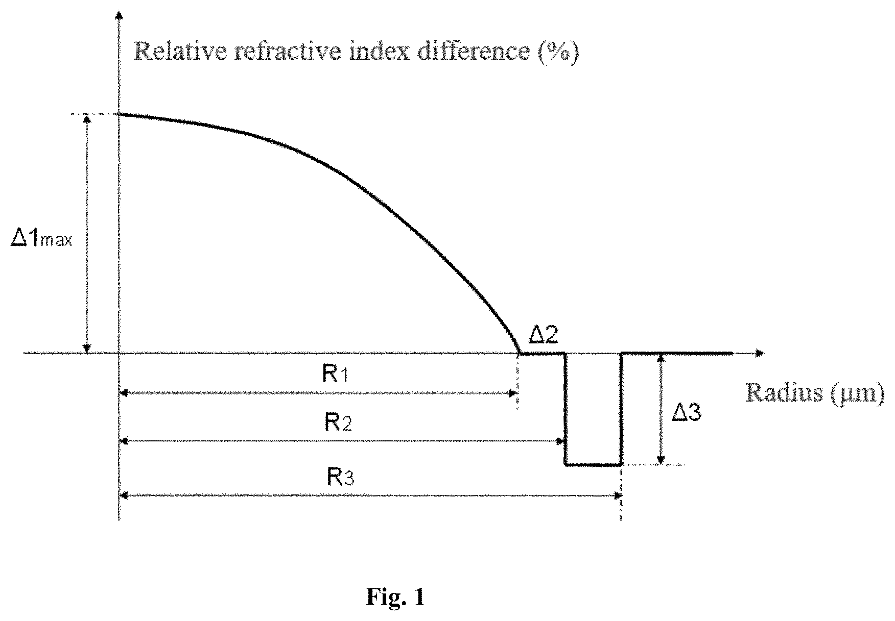
[0027] FIG. 1 schematically shows a refractive index profile of one embodiment of the present invention;
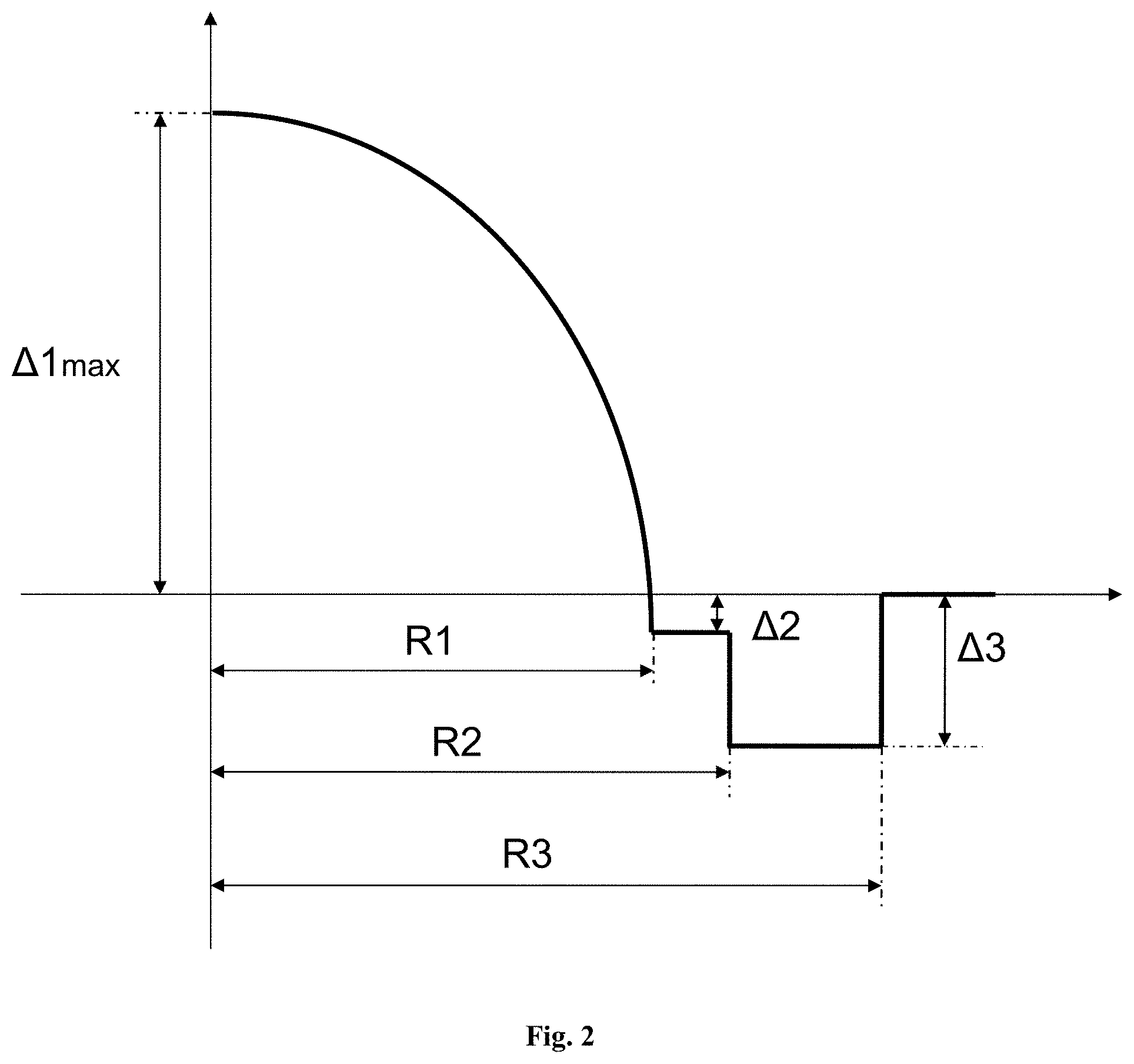
[0028] FIG. 2 schematically shows a refractive index profile of another embodiment of the present invention;
[0029] FIG. 3 schematically shows a relationship between a mode field diameter of a fundamental mode LP.sub.01 at 1310 nm and a core diameter R1 and (.DELTA.1 max-.DELTA.2) of the present invention;
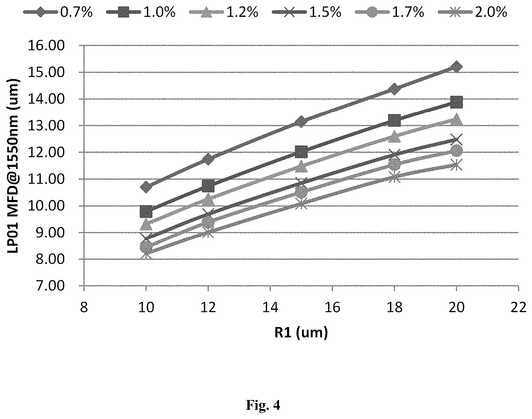
[0030] FIG. 4 schematically shows a relationship between a mode field diameter of a fundamental mode LP.sub.01 at 1550 nm and a core diameter R1 and (.DELTA.1 max-.DELTA.2) of the present invention; and
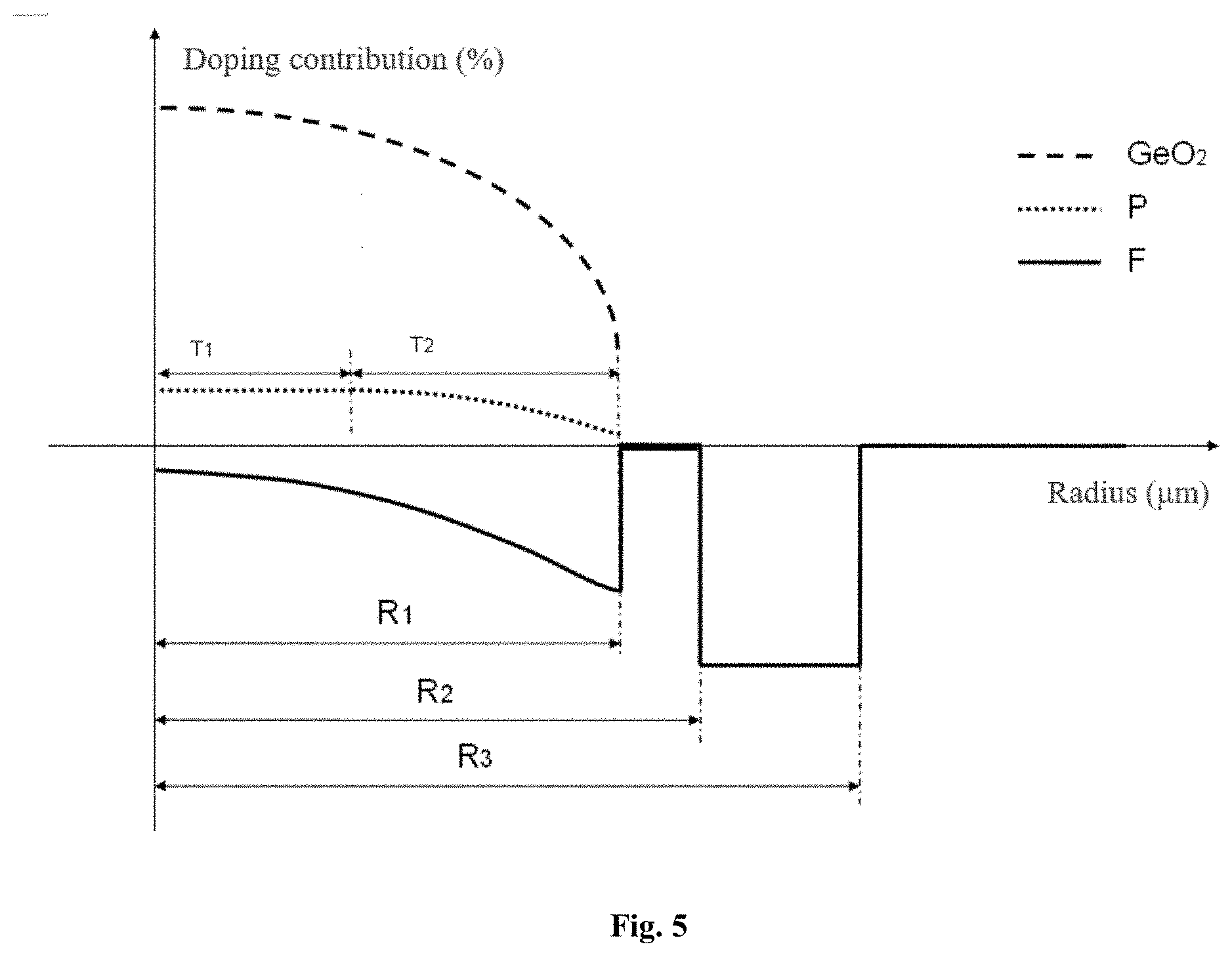
[0031] FIG. 5 schematically shows a doping amount profile of one embodiment of the present invention.
DETAILED DESCRIPTION OF THE INVENTION
[0032] Specific embodiments will be given below to further illustrate the present invention.
[0033] A fiber comprises a core layer and a cladding. The core layer has a parabolic refractive index profile with .alpha. in a range from 1.9 to 2.1, a radius R1, and a maximum relative refractive index difference .DELTA.1 max in a range from 0.7% to 1.7% at a core layer center. The contribution of P at the core layer center is .DELTA.P0; the contribution of P at a boundary between a flat region and a graded region is .DELTA.P1; the contribution fluctuation of P at a boundary of the core layer center and the flat region is
.DELTA. P 10 = 2 .DELTA. P 1 - .DELTA. P 0 .DELTA. P 1 + .DELTA. P 0 . ##EQU00003##
The flat region has a width T1, and the graded region has a width T2=R1-T1. The contribution of P at an outer edge of the core layer is .DELTA.P2, and the contribution difference of P between the flat region and an outer edge of the graded region is .DELTA.P21=.DELTA.P2-.DELTA.P1. The contribution of F at the core layer center is .DELTA.F0, and the contribution of F at an edge of the core layer is .DELTA.F1. The cladding has an inner cladding layer, a depressed cladding layer, and an outer cladding layer from inside to outside thereof. The inner cladding layer has a radius R2 and a relative refractive index difference .DELTA.2; the depressed cladding layer has radius R3 and a relative refractive index difference .DELTA.3; and the outer cladding layer is a pure silica glass layer with a radius of 62.5 .mu.m.
[0034] According to the present invention, a set of preforms are prepared, drawn, and coated with double layers. The structure and main performance parameters of the fiber are shown in Table 1.
[0035] Macrobending loss is tested as follows. The fiber under test is wound one turn to form a circle with a certain diameter (for example, 10 mm, 15 mm, 20 mm, 30 mm, etc.), and the circle is then released. A change in optical power after the winding relative to that before the winding is tested as the macrobending loss of the fiber.
[0036] The overfilled bandwidth is measured according to the FOTP-204 method, and the test adopts the overfilled condition.
TABLE-US-00001 TABLE 1 Main structure parameters and performance parameters of the fiber Examples Main parameters of the fiber 1 2 3 4 R1 (.mu.m) 15.2 14.3 18.5 12.4 .DELTA.1max (%) 1.19 1.10 1.48 0.98 Core layer .alpha. 2.070 2.052 2.028 2.042 .DELTA.F0 (%) -0.02 -0.04 -0.08 -0.04 .DELTA.F1 (%) -0.23 -0.32 -0.38 -0.25 T1 (.mu.m) 2.6 11.8 6.8 7.9 T2 (.mu.m) 12.6 2.5 11.7 4.5 .DELTA.P0 (%) 0.08 0.17 0.13 0.18 .DELTA.P10 (%) 1.7 2.8 4.3 4.4 .DELTA.P21 (%) -0.07 -0.11 -0.08 -0.15 .DELTA.P2 (%) 0.01 0.06 0.05 0.03 R2 (.mu.m) 16.2 17.4 21.1 14.1 .DELTA.2 (%) -0.05 -0.18 -0.01 -0.29 R3 (.mu.m) 22.0 22.3 28.4 17.7 .DELTA.3 (%) -0.35 -0.48 -0.56 -0.60 overfilled bandwidth at 850 nm (MHz-km) 5181 6300 3872 8394 overfilled bandwidth at 950 nm (MHz-km) 2740 3427 2303 3377 overfilled bandwidth at 1300 nm (MHz-km) 799 650 550 792 macrobending loss with a 7.5 mm-bending 0.05 0.03 0.01 0.02 radius and two turns at 850 nm (dB) macrobending loss with a 7.5 mm-bending 0.10 0.08 0.02 0.05 radius and two turns at 1300 nm (dB) LP.sub.01 MFD at 1310 nm (.mu.m) 10.6 10.3 11.0 9.4 LP.sub.01 MFD at 1550 nm (.mu.m) 11.5 11.2 11.9 10.2
[0037] The small core-diameter graded-index optical fiber has a smaller core diameter, less guided modes, and theoretically a higher bandwidth than a conventional multimode fiber. In order to satisfy the conditions of multimode transmission and reduce inter-mode dispersion in fibers, the core layer refractive index profile of the small core-diameter graded-index optical fiber adopts a design of an ".alpha. profile" similar to that of the conventional multimode fiber. In order to perform single-mode transmission, the small core-diameter graded-index optical fiber is enabled to have a mode field diameter (MFD) of a fundamental mode LP.sub.01 in a single-mode transmission window matched with the MFD of the conventional single-mode fiber by means of an appropriate refractive index profile design. When applied to integrated systems such as narrow cabinets, wiring boxes, etc., the fiber will undergo a very small bending radius. High-order modes transmitted near an edge of the fiber core easily suffer from leakage, thus causing signal loss. The small core-diameter graded-index optical fiber limits leakage of higher-order modes by adding a low refractive index region in the fiber cladding, thus minimizing signal loss.
[0038] When used for single-mode transmission, the small core-diameter graded-index optical fiber is in quasi-single-mode transmission, and its coupling with the single-mode fiber is related to the matching degree of the mode field diameters of the fundamental modes LP01 therebetween. The tolerance of the mode field diameters directly influences the splice loss of the fibers. Studies have shown that the splice loss of two single-mode fibers with mode field diameters of d.sub.1 and d.sub.2 respectively can be expressed as follows:
.alpha. s = 20 log d 1 2 + d 2 2 2 d 1 d 2 . ##EQU00004##
ideally, when d.sub.1=d.sub.2, i.e., the two fibers have the same the mode field diameter, the splice loss .alpha..sub.s=0.
[0039] The center value of the mode field diameter specified under the ITU-T G.652.D standard is in a range from 8.6 .mu.m to 9.5 .mu.m.+-.0.6 .mu.m. Therefore, for G.652 fibers with MFDs of 8.6 .mu.m and 9.5 .mu.m, respectively, at 1310 nm, if the coupling loss is to be controlled within 0.1 dB, the MFDs of fundamental modes LP01 of the small core-diameter graded-index optical fibers at 1310 nm have to be in a range from 7.4 to 10 .mu.m and in a range from 8.2 to 11 .mu.m, respectively. For single-mode fibers with MFDs of 10 .mu.m and 11 .mu.m, respectively, at 1550 nm, if the coupling loss is to be controlled within 0.1 dB, the MFDs of the fundamental modes LP01 of the small core-diameter graded-index optical fibers at 1550 nm have to be in a range from 8.6 to 11.6 .mu.m and in a range from 9.5 to 12.8 .mu.m, respectively.
[0040] In sum, the invention relates to a small core-diameter graded-index optical fiber including a core layer and a cladding which includes an inner cladding layer, a depressed cladding layer, and an outer cladding layer from inside to outside thereof. The core layer has a parabolic refractive index profile with a distribution index .alpha. in a range from 1.9 to 2.1, a radius R1 in a range from 10 to 21 .mu.m, and a maximum relative refractive index difference .DELTA.1 max in a range from 0.7% to 1.7% at a core layer center, and is a silica glass layer co-doped with germanium Ge, phosphorus P, and fluoride F. The inner cladding layer is a pure silica layer or an F-doped silica glass layer, and has a unilateral width in a range from 0.5 to 5 .mu.m and a .DELTA.2 in a range from -0.4% to 0%. The depressed cladding layer has a unilateral width in a range from 2 to 10 .mu.m and a .DELTA.3 in a range from -0.8% to -0.2%. The outer cladding layer is a pure silica glass layer. The fiber not only is compatible with existing OM3/OM4 multimode fibers, but also can support the wavelength-division multiplexing technology in a wavelength range from 850 nm to 950 nm. The fiber is also compatible with a single-mode fiber, and can support 1310 nm or 1550 nm single-mode transmission. The fiber has excellent bending resistance and is suitable for use in an access network or a miniaturized optical device.
[0041] The foregoing description of the exemplary embodiments of the invention has been presented only for the purposes of illustration and description and is not intended to be exhaustive or to limit the invention to the precise forms disclosed. Many modifications and variations are possible in light of the above teaching.
[0042] While there has been shown several and alternate embodiments of the present invention, it is to be understood that certain changes can be made as would be known to one skilled in the art without departing from the underlying scope of the invention as is discussed and set forth above and below including claims and drawings. Furthermore, the embodiments described above are only intended to illustrate the principles of the present invention and are not intended to limit the scope of the invention to the disclosed elements.
* * * * *
D00000
D00001
D00002
D00003
D00004
D00005
XML
uspto.report is an independent third-party trademark research tool that is not affiliated, endorsed, or sponsored by the United States Patent and Trademark Office (USPTO) or any other governmental organization. The information provided by uspto.report is based on publicly available data at the time of writing and is intended for informational purposes only.
While we strive to provide accurate and up-to-date information, we do not guarantee the accuracy, completeness, reliability, or suitability of the information displayed on this site. The use of this site is at your own risk. Any reliance you place on such information is therefore strictly at your own risk.
All official trademark data, including owner information, should be verified by visiting the official USPTO website at www.uspto.gov. This site is not intended to replace professional legal advice and should not be used as a substitute for consulting with a legal professional who is knowledgeable about trademark law.