Transmission And Method For Producing Such A Transmission
Papies; Jennifer
U.S. patent application number 16/576373 was filed with the patent office on 2020-03-26 for transmission and method for producing such a transmission. This patent application is currently assigned to FLENDER GMBH. The applicant listed for this patent is FLENDER GMBH. Invention is credited to Jennifer Papies.
| Application Number | 20200096088 16/576373 |
| Document ID | / |
| Family ID | 63667747 |
| Filed Date | 2020-03-26 |

| United States Patent Application | 20200096088 |
| Kind Code | A1 |
| Papies; Jennifer | March 26, 2020 |
TRANSMISSION AND METHOD FOR PRODUCING SUCH A TRANSMISSION
Abstract
A transmission includes a housing made from a metallic material and is provided with a cooling structure in the form of a cooling element made from open-cell metal foam. The cooling element can be secured on the housing, in particular on an outer surface of the housing, by a screw connection and/or adhesive bonding and/or magnetically.
| Inventors: | Papies; Jennifer; (Bochum, DE) | ||||||||||
| Applicant: |
|
||||||||||
|---|---|---|---|---|---|---|---|---|---|---|---|
| Assignee: | FLENDER GMBH Bocholt DE |
||||||||||
| Family ID: | 63667747 | ||||||||||
| Appl. No.: | 16/576373 | ||||||||||
| Filed: | September 19, 2019 |
| Current U.S. Class: | 1/1 |
| Current CPC Class: | F16H 57/0416 20130101; B32B 15/046 20130101; B32B 15/20 20130101; B32B 7/12 20130101; F16H 57/0419 20130101; B32B 2266/06 20130101; F16H 57/032 20130101 |
| International Class: | F16H 57/04 20060101 F16H057/04; B32B 15/04 20060101 B32B015/04; B32B 15/20 20060101 B32B015/20; B32B 7/12 20060101 B32B007/12; F16H 57/032 20060101 F16H057/032 |
Foreign Application Data
| Date | Code | Application Number |
|---|---|---|
| Sep 20, 2018 | EP | 18195645.9 |
Claims
1. A transmission, comprising a housing made from a metallic material and including a cooling structure, said cooling structure including a cooling element made from open-cell metal foam and secured on the housing.
2. The transmission of claim 1, wherein the cooling element is secured on an outer surface of the housing.
3. The transmission of claim 1, wherein the cooling element is made of aluminum or copper.
4. The transmission of claim 1, wherein the cooling element has a plate-shaped configuration.
5. The transmission of claim 1, further comprising an intermediate layer containing silicone and thermally conductive particles and provided between the cooling element and the housing.
6. The transmission of claim 1, wherein the cooling element is secured on the housing by a screw connection and/or adhesive bonding.
7. The transmission of claim 1, wherein the cooling element is secured on the housing by a magnet.
8. A method for producing a transmission, said method comprising securing on a housing made from a metallic material a cooling element made from open-cell metal foam to provide a cooling structure on the housing.
9. The method of claim 8, further comprising providing an intermediate layer containing silicone and thermally conductive particles between the cooling element and the housing.
10. The method of claim 8, wherein the cooling element is secured on the housing by a screw connection and/or adhesive bonding and/or magnetically.
Description
CROSS-REFERENCES TO RELATED APPLICATIONS
[0001] This application claims the priority of European Patent Application, Serial No. 18195645.9, filed Sep. 20, 2018, pursuant to 35 U.S.C. 119(a)-(d), the disclosure of which is incorporated herein by reference in its entirety as if fully set forth herein.
BACKGROUND OF THE INVENTION
[0002] The present invention relates to a transmission and to a method for producing such a transmission.
[0003] The following discussion of related art is provided to assist the reader in understanding the advantages of the invention, and is not to be construed as an admission that this related art is prior art to this invention.
[0004] A crucial factor in the transmission engineering sector involves dissipation of heat, generated in the transmission, from the transmission housing so as to ensure proper operation of the transmission for an extended period. For this purpose, the transmission can be provided with an active cooling device. As an alternative or in addition, a passive cooling system can be provided by increasing a housing surface area through the provision of cooling structures in the form of cooling fins, for example. However, housings with such cooling fins become very expensive when compared with housings without cooling fins. Moreover, the formation of cooling fins is associated with a relatively large increase in the dead weight of the housing, which is undesirable in many cases.
[0005] It would therefore be desirable and advantageous to provide an improved transmission which obviates prior art shortcomings and which can be produced in a simple and low-cost manner while still being reliable in operation and enabling flexible adjustment of the cooling capacity to suit any demand.
SUMMARY OF THE INVENTION
[0006] According to one aspect of the present invention, a transmission includes a housing made from a metallic material and including a cooling structure, the cooling structure including a cooling element made from open-cell metal foam and secured on the housing.
[0007] According to another advantageous feature of the present invention, the cooling element can be secured on an outer surface of the housing.
[0008] In the following description, the reference to "a cooling element" should not be limited to the presence of a single cooling element but is used in a generic sense and the principles described in the following description with respect to a cooling element are equally applicable to the presence of any number of such cooling elements.
[0009] A significant advantage of providing cooling elements made from open-cell metal foam over conventional cooling fins resides in a significantly larger surface area and improved cooling capacity associated therewith. Moreover, such cooling elements made from open-cell metal foam have a lower dead weight than cooling fins, so that the housing of a transmission according to the invention can be made lighter than a housing with cooling fins while still maintaining a comparable cooling capacity. Another advantage associated with the use of separate cooling elements made from open-cell metal foam is that the cooling elements can be secured later on to suit a demand at hand, for example a housing manufactured by casting. This allows simple and flexible adjustment of the cooling capacity to the demand at hand. In particular, such retrofitting of cooling elements makes it possible to achieve a wide range of cooling capacities on the basis of a standard housing, and this allows low-cost series manufacture when housings of essentially same design with different cooling capacity are required.
[0010] According to another advantageous feature of the present invention, the cooling element can be made of aluminum or copper. Using aluminum and copper has the benefits of good thermal conductivity, while at the same time being of low weight.
[0011] According to another advantageous feature of the present invention, the cooling element can have a plate-shaped configuration. This allows simple and flexible handling. For example, the shape of the underside can be matched to the shape of a region of the outer surface of the housing. Thus, the cooling element can have an underside in the form of a circular ring segment to enable its simple securement on a housing, the outer surface of which is likewise in the form of a circular ring segment, at least in one region thereof.
[0012] According to another advantageous feature of the present invention, an intermediate layer containing silicone and thermally conductive particles can be provided between the cooling element and the housing. This is advantageous especially when the surface of the housing on which the cooling element is to be arranged is uneven, as is often the case when the housing is produced by casting, for example.
[0013] According to another advantageous feature of the present invention, the cooling element can be secured on the housing by a screw connection and/or adhesive bonding. This allows very simple mounting of the cooling element on the housing. As an alternative or in addition, the cooling element can be secured on the housing by a magnet.
[0014] According to another aspect of the present invention, a method for producing a transmission includes securing on a housing made from a metallic material a cooling element made from open-cell metal foam to provide a cooling structure on the housing.
[0015] According to another advantageous feature of the present invention, an intermediate layer containing silicone and thermally conductive particles can be provided between the cooling element and the housing. As a result, irregularities in the housing surface in particular can be compensated.
[0016] According to another advantageous feature of the present invention, the cooling element can be secured on the housing by a screw connection and/or adhesive bonding and/or magnetically.
BRIEF DESCRIPTION OF THE DRAWING
[0017] Other features and advantages of the present invention will be more readily apparent upon reading the following description of currently preferred exemplified embodiments of the invention with reference to the accompanying drawing, in which:
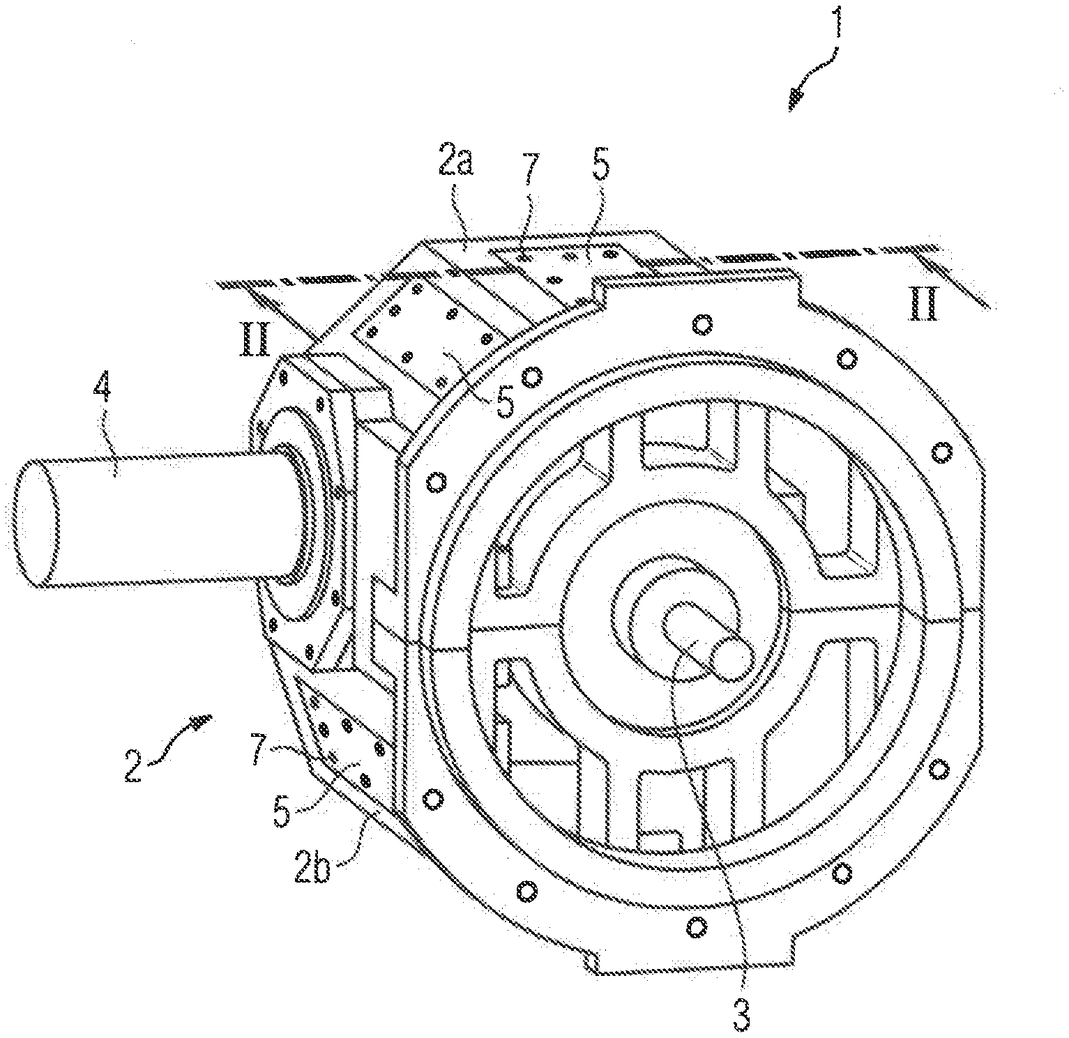
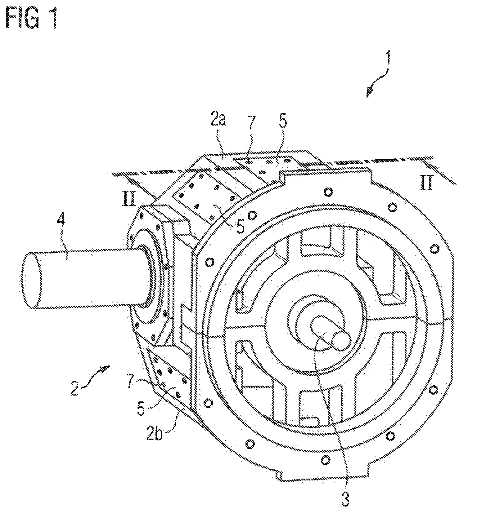
[0018] FIG. 1 is a schematic perspective view of a transmission according to present invention, depicting the presence of cooling elements arranged thereon, and
[0019] FIG. 2 is an enlarged cross section of the transmission of FIG. 1, taken along a section line II-II in FIG. 1.
DETAILED DESCRIPTION OF PREFERRED EMBODIMENTS
[0020] Throughout all the figures, same or corresponding elements may generally be indicated by same reference numerals. These depicted embodiments are to be understood as illustrative of the invention and not as limiting in any way. It should also be understood that the figures are not necessarily to scale and that the embodiments may be illustrated by graphic symbols, phantom lines, diagrammatic representations and fragmentary views. In certain instances, details which are not necessary for an understanding of the present invention or which render other details difficult to perceive may have been omitted.
[0021] Turning now to the drawing, and in particular to FIG. 1, there is shown a schematic perspective view of a transmission according to present invention, generally designated by reference numeral 1. In the non-limiting example shown here, the transmission 1 is embodied as a spur gear transmission configured as a bevel-and-spur gear train. However, it will be understood that the principles described in the following description with respect to the transmission 1 are equally applicable to any other type of transmission and the specific type of transmission is of no significance for the present invention.
[0022] The transmission 1 has a housing 2, which is divided into a housing top part 2a and a housing bottom part 2b. In the present case, the housing top part 2a and the housing bottom part 2b are of symmetrical construction and can be cast in a same die, although this is not obligatory. The transmission 1 furthermore includes an input shaft 3, via which the driving power enters the transmission 1, and an output shaft 4, which can be connected to a system (not illustrated), e.g. a conveyor belt system. Cooling structures in the form of a plurality of cooling elements 5 are arranged on the outside of the housing 2, with each cooling element 5 being made from open-cell metal foam and secured as a separate component on the housing 2. In the present case, each of the cooling elements 5 has a plate-shaped configuration and is manufactured from aluminum.
[0023] Provided between each of the cooling elements 5 and the housing 2 is an intermediate layer 6 which contains silicone and thermally conductive particles and is generally referred to as a "gap filler". By way of example, the cooling elements 5 are secured here on the housing 2 using screws 7. As an alternative or in addition, however, the cooling elements 5 can also be secured by adhesive bonding and/or using magnets. In the latter case, the cooling elements 5, of course, must be provided with corresponding magnets, which are not illustrated here.
[0024] To produce the housing illustrated hi MG. 1, the transmission 1 is assembled hi known manner in a first step. In a further step, the separate cooling elements 5 are then positioned and secured on an outer surface of the housing 2. Here, the number and position of the individual cooling elements 5 can be chosen according to a desired cooling capacity. In order to ensure good thermal coupling of the cooling elements 5 to the housing 2, despite the presence of uneven outer surface of the housing 2 produced by casting, an intermediate layer 6 which compensates irregularities in the outer surface of the housing 2 is positioned between each of the cooling elements 5 and the housing 2.
[0025] A significant advantage of a transmission 1 according to the present invention over a conventional transmission of same construction but provided with cooling fins is that the transmission 1 according to the present invention has a lower dead weight as a result of the use of cooling structures in the form of one or more cooling elements 5. Moreover, the production of the housing 2 or of the housing top and bottom parts 2a, 2b by casting is significantly cheaper due to the absence of cooling fins. Another advantage relates to the cooling capacity of the transmission 1, which cooling capacity is realized by the presence of cooling elements 5 and can be adjusted in a manner which is flexible and best suited to the demand at hand through suitable choice of shape, number and position of the cooling elements 5. Thus, it is also possible to provide transmissions of same construction with different cooling capacities using housings 2 of the same construction, so that series manufacture becomes much easier.
[0026] Although the invention has been illustrated and described more specifically in detail by means of a preferred illustrative embodiment, the invention is not restricted by the examples disclosed, and other variations can be derived by a person skilled in the art without departing in any way from the spirit and scope of the present invention. Thus, the cooling elements 5 can have a configuration that differs from a plate shape. It is also possible for the underside of the cooling elements 5 to be matched to a shape of the housing outer surface. The embodiments were chosen and described in order to explain the principles of the invention and practical application to thereby enable a person skilled in the art to best utilize the invention and various embodiments with various modifications as are suited to the particular use contemplated.
[0027] What is claimed as new and desired to be protected by Letters Patent is set forth in the appended claims and includes equivalents of the elements recited therein:
* * * * *
D00000
D00001
D00002
XML
uspto.report is an independent third-party trademark research tool that is not affiliated, endorsed, or sponsored by the United States Patent and Trademark Office (USPTO) or any other governmental organization. The information provided by uspto.report is based on publicly available data at the time of writing and is intended for informational purposes only.
While we strive to provide accurate and up-to-date information, we do not guarantee the accuracy, completeness, reliability, or suitability of the information displayed on this site. The use of this site is at your own risk. Any reliance you place on such information is therefore strictly at your own risk.
All official trademark data, including owner information, should be verified by visiting the official USPTO website at www.uspto.gov. This site is not intended to replace professional legal advice and should not be used as a substitute for consulting with a legal professional who is knowledgeable about trademark law.