Configurable Ovoid Units Including Adjustable Ovoids, Earth-boring Tools Including The Same, And Related Methods
Etebu; Ebitimitula ; et al.
U.S. patent application number 16/139618 was filed with the patent office on 2020-03-26 for configurable ovoid units including adjustable ovoids, earth-boring tools including the same, and related methods. The applicant listed for this patent is Baker Hughes, a GE company, LLC. Invention is credited to Ebitimitula Etebu, Steven W. Webb.
| Application Number | 20200095831 16/139618 |
| Document ID | / |
| Family ID | 69885352 |
| Filed Date | 2020-03-26 |


View All Diagrams
| United States Patent Application | 20200095831 |
| Kind Code | A1 |
| Etebu; Ebitimitula ; et al. | March 26, 2020 |
CONFIGURABLE OVOID UNITS INCLUDING ADJUSTABLE OVOIDS, EARTH-BORING TOOLS INCLUDING THE SAME, AND RELATED METHODS
Abstract
Configurable ovoid units, earth-boring tools including configurable ovoid units, and related methods are disclosed. An earth-boring tool may include a body including at least one blade. The earth-boring tool may further include a cutting element secured to the at least one blade and including at least one sensor configured to sense at least one condition of the cutting element. Moreover, the earth-boring tool may include at least one configurable ovoid unit disposed at least partially within the at least one blade and comprising an adjustable ovoid head. Additionally, the earth-boring tool may include a control module disposed within the earth-boring drilling tool. The control module may be configured to receive sensor data from the at least one sensor, and to convey at least one signal to the at least one ovoid unit for configuring the at least one ovoid unit in response to the sensor data.
| Inventors: | Etebu; Ebitimitula; (Spring, TX) ; Webb; Steven W.; (The Woodlands, TX) | ||||||||||
| Applicant: |
|
||||||||||
|---|---|---|---|---|---|---|---|---|---|---|---|
| Family ID: | 69885352 | ||||||||||
| Appl. No.: | 16/139618 | ||||||||||
| Filed: | September 24, 2018 |
| Current U.S. Class: | 1/1 |
| Current CPC Class: | E21B 47/017 20200501; E21B 10/43 20130101; E21B 10/633 20130101; E21B 10/20 20130101; E21B 10/627 20130101; E21B 47/07 20200501; E21B 47/12 20130101 |
| International Class: | E21B 10/633 20060101 E21B010/633; E21B 10/20 20060101 E21B010/20 |
Claims
1. An earth-boring tool, comprising: a body including at least one blade; a cutting element secured to the at least one blade and including at least one sensor configured to sense at least one condition of the cutting element; at least one configurable ovoid unit disposed at least partially within the at least one blade and comprising an adjustable ovoid head; and a control module disposed within the earth-boring tool and configured to: receive sensor data from the at least one sensor of the cutting element; and convey at least one signal to the at least one ovoid unit for configuring the at least one ovoid unit in response to the sensor data.
2. The earth-boring tool of claim 1, wherein the at least one sensor comprises at least one temperature sensor for sensing a temperature of the cutting element.
3. The earth-boring tool of claim 1, wherein the adjustable ovoid head is configured to extend from the at least one blade in a first direction, wherein the adjustable ovoid head is further configured to retract in a second, opposite direction in response to one or more conditions.
4. The earth-boring tool of claim 1, wherein the body includes at least one port for receiving at least one wire, the at least one wire coupling the control module to at least one of the cutting element and the at least one configurable ovoid unit.
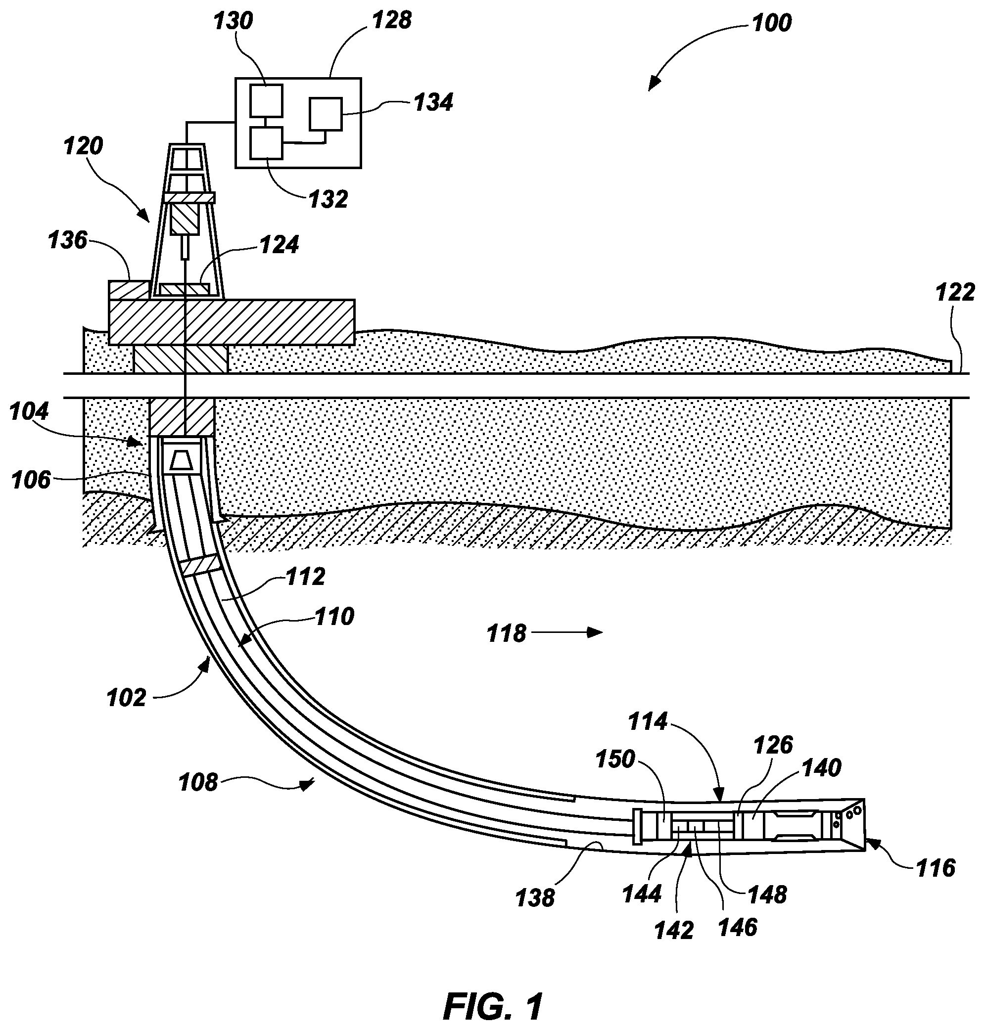
5. The earth-boring tool of claim 1, wherein the at least one configurable ovoid unit further comprises an actuator configured to generate an axial extension motion in response to the at least one signal.
6. The earth-boring tool of claim 5, wherein the at least one configurable ovoid unit further comprises a valve configured to close in response to the axial extension motion.
7. The earth-boring tool of claim 6, wherein the at least one configurable ovoid unit further comprises a restrictor configured to receive flow in response to the valve being in an open position.
8. The earth-boring tool of claim 1, wherein the at least one configurable ovoid unit comprises a replaceable, configurable ovoid unit.
9. The earth-boring tool of claim 1, wherein the body includes at least one internal chamber for receiving at least one wire, the at least one wire coupling the control module to at least one of the cutting element and the at least one configurable ovoid unit.
10. An ovoid unit, comprising: an actuator configured to receive a signal; a valve coupled to the actuator and configured to be in one of a first state and a second, different state based on the actuator; and an adjustable ovoid head coupled to the actuator and configured to be in a retractable configuration in response to the valve being in the first state and a non-retractable configuration in response to the valve being in the second, different state.
11. The ovoid unit of claim 10, wherein the adjustable ovoid head may retract in response to an external force applied thereto while in the retractable configuration.
12. The ovoid unit of claim 10, wherein the valve is configured to be in the second, different state in response to the actuator receiving the signal.
13. The ovoid unit of claim 12, wherein the second, different state is a closed state and the first state is an open state.
14. A method of operating an earth-boring tool, the method comprising: sensing at least one condition of a cutting element secured to at least one blade of an earth-boring tool; and adjusting, based on the at least one sensed condition, a configuration of at least one configurable ovoid unit at least partially disposed within the at least one blade.
15. The method of claim 14, wherein sensing the at least one condition comprises sensing a temperature of the cutting element.
16. The method of claim 15, wherein adjusting the configuration of the at least one configurable ovoid unit comprises configuring the ovoid unit to be in a non-retractable configuration in response to the temperature being greater than a temperature threshold.
17. The method of claim 14, wherein the adjusting the configuration of the at least one configurable ovoid unit comprises one of opening a valve of the at least one configurable ovoid unit and closing the valve of the at least one configurable ovoid unit.
18. The method of claim 14, further comprising comparing the at least one sensed condition to one or more threshold conditions.
19. The method of claim 18, wherein the comparing the at least one sensed condition to the one or more threshold conditions comprises comparing at least one sensed temperature to one or more temperature thresholds.
20. The method of claim 19, wherein the adjusting the configuration of the at least one configurable ovoid unit comprises: transmitting a signal to the at least one configurable ovoid unit to configure the ovoid unit in a non-retractable configuration in response to the temperature being greater than a first temperature threshold of the one or more temperature thresholds; and ceasing transmission of the signal to the at least one configurable ovoid unit to configure the ovoid unit in a retractable configuration in response to the temperature being less than a second temperature threshold of the one or more temperature thresholds.
Description
TECHNICAL FIELD
[0001] The present disclosure generally relates to configurable ovoid units, earth-boring tools, and related methods of drilling. More particularly, embodiments of the present disclosure relate to configurable ovoid units including an adjustable ovoid, to earth-boring tools including one or more configurable ovoid units, and to related methods.
BACKGROUND
[0002] The oil and gas industry expends sizable sums to design cutting tools, such as downhole drill bits including roller cone rock bits and fixed-cutter bits. Such drill bits may have relatively long service lives with relatively infrequent failure. In particular, considerable sums are expended to design and manufacture roller cone rock bits and fixed-cutter bits in a manner that minimizes the probability of catastrophic drill bit failure during drilling operations. The loss of a roller cone or a polycrystalline diamond compact from a bit during drilling operations can impede the drilling operations and, at worst, necessitate rather expensive fishing operations.
[0003] Diagnostic information related to a drill bit and certain components of the drill bit is valuable and may be linked to the durability, performance, and the potential failure of the drill bit. Characteristic information regarding the rock formation is also valuable and may be used to estimate performance and other features related to drilling operations.
SUMMARY
[0004] Various embodiments of the present disclosure include an earth-boring tool. The earth-boring tool may include a body including at least one blade. The earth-boring tool may further include a cutting element secured to the at least one blade and including at least one sensor configured to sense at least one condition of the cutting element. Moreover, the earth-boring tool may include at least one configurable ovoid unit disposed at least partially within the at least one blade. The at least one configurable ovoid unit may include an adjustable ovoid head. Additionally, the earth-boring tool may include a control module disposed within the earth-boring tool. The control module may be configured to receive sensor data from the at least one sensor of the cutting element. Further, the control module may be configured to convey at least one signal to the at least one ovoid unit for configuring the at least one ovoid unit in response to the sensor data.
[0005] Another embodiment includes an ovoid unit. The ovoid unit may include an actuator configured to receive a signal. The ovoid unit may further include a valve coupled to the actuator and configured to be in one of a first state and a second, different state based on the actuator. The ovoid unit may further include an adjustable ovoid head coupled to the actuator. The ovoid head may be configured to be in a retractable configuration in response to the valve being in the first state. Further, the ovoid head may be configured to be in a non-retractable configuration in response to the valve being in the second, different state.
[0006] Another embodiment includes a method of operating an earth-boring tool. The method may include sensing at least one condition of a cutting element secured to at least one blade of an earth-boring tool. The method may further include adjusting, based on the at least one sensed condition, a configuration of at least one configurable ovoid unit at least partially disposed within the at least one blade.
BRIEF DESCRIPTION OF THE DRAWINGS
[0007] FIG. 1 is a schematic diagram of an example wellbore system including a drill string that includes an earth-boring tool, according to one or more embodiments of the disclosure;
[0008] FIG. 2 is a perspective view of an example earth-boring tool, according to one or more embodiments of the disclosure;
[0009] FIG. 3 is a perspective view of an example cutting element, in accordance with one or more embodiments of the disclosure;
[0010] FIG. 4 is a schematic diagram of an example earth-boring tool including a configurable ovoid unit, in accordance with one or more embodiments of the disclosure;
[0011] FIG. 5 illustrates an example earth-boring tool including at least one port, according to one or more embodiments of the disclosure;
[0012] FIG. 6 is a cut away view of an example earth-boring tool including internal chambers, according to one or more embodiments of the disclosure;
[0013] FIGS. 7A-7C are cross-sectional side views of an example configurable ovoid unit, in accordance with one or more embodiments of the disclosure;
[0014] FIG. 8 is a flowchart depicting an example method of operating an earth-boring tool, according to various embodiments of the disclosure; and
[0015] FIG. 9 is a block diagram of an example control module.
DETAILED DESCRIPTION
[0016] The illustrations presented herein are not actual views of any drill bit, roller cutter, ovoid unit, ovoid, or any component thereof, but are merely idealized representations, which are employed to describe embodiments of the present disclosure.
[0017] As used herein, the terms "bit" and "earth-boring tool" each mean and include earth-boring tools for forming, enlarging, or forming and enlarging a borehole. Non-limiting examples of bits include fixed cutter (drag) bits, fixed cutter coring bits, fixed cutter eccentric bits, fixed cutter bi-center bits, fixed cutter reamers, expandable reamers with blades bearing fixed cutters, and hybrid bits including both fixed cutters and rotatable cutting structures (roller cones).
[0018] As used herein, the term "cutting structure" means and include any element that is configured for use on an earth-boring tool and for removing formation material from the formation within a wellbore during operation of the earth-boring tool. As non-limiting examples, cutting structures include rotatable cutting structures, commonly referred to in the art as "roller cones" or "rolling cones."
[0019] As used herein, the term "cutting elements" means and includes, for example, superabrasive (e.g., polycrystalline diamond compact or "PDC") cutting elements employed as fixed cutting elements, as well as tungsten carbide inserts and superabrasive inserts employed as cutting elements mounted to rotatable cutting structures, such as roller cones. Additionally, in regard to rotatable cutting structures, the term "cutting elements" includes both milled teeth and/or PDC cutting elements. Moreover, the term "cutting elements" includes tungsten carbide inserts.
[0020] As used herein, the singular forms following "a," "an," and "the" are intended to include the plural forms as well, unless the context clearly indicates otherwise.
[0021] As used herein, the term "may" with respect to a material, structure, feature, or method act indicates that such is contemplated for use in implementation of an embodiment of the disclosure, and such term is used in preference to the more restrictive term "is" so as to avoid any implication that other compatible materials, structures, features, and methods usable in combination therewith should or must be excluded.
[0022] As used herein, any relational term, such as "first," "second," "top," "bottom," etc., is used for clarity and convenience in understanding the disclosure and accompanying drawings, and does not connote or depend on any specific preference or order, except where the context clearly indicates otherwise. For example, these terms may refer to an orientation of elements of an earth-boring tool when disposed within a borehole in a conventional manner. Furthermore, these terms may refer to an orientation of elements of an earth-boring tool as illustrated in the drawings.
[0023] As used in the present disclosure, the terms "module" or "component" may refer to specific hardware implementations configured to perform the actions of the module or component and/or software objects or software routines that may be stored on and/or executed by general purpose hardware (e.g., computer-readable media, processing devices, etc.) of the computing system. In some embodiments, the different components, modules, engines, and services described in the present disclosure may be implemented as objects or processes that execute on the computing system (e.g., as separate threads). While some of the system and methods described in the present disclosure are generally described as being implemented in software (stored on and/or executed by general purpose hardware), specific hardware implementations or a combination of software and specific hardware implementations are also possible and contemplated.
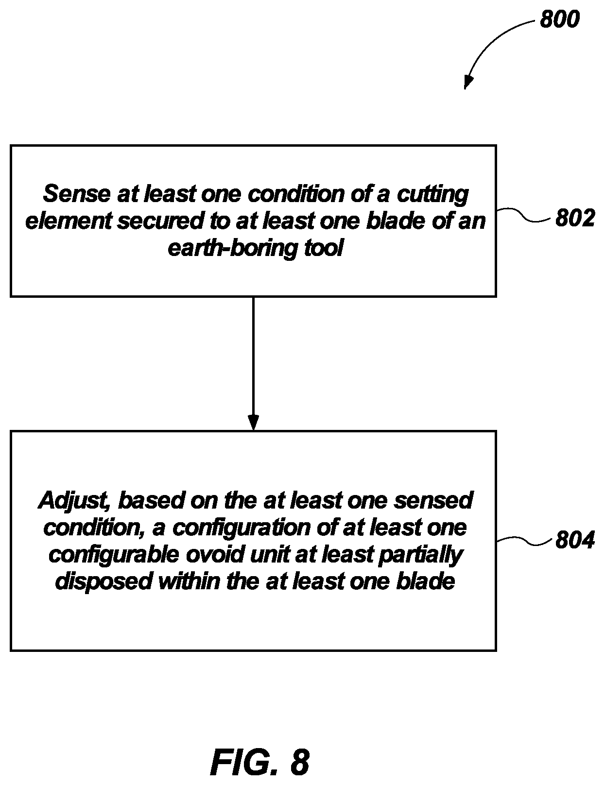
[0024] As used herein, the term "about" used in reference to a given parameter is inclusive of the stated value and has the meaning dictated by the context (e.g., it includes the degree of error associated with measurement of the given parameter, as well as variations resulting from manufacturing tolerances, etc.).
[0025] As used herein, the term "substantially" in reference to a given parameter, property, or condition means and includes to a degree that one skilled in the art would understand that the given parameter, property, or condition is met with a small degree of variance, such as within acceptable manufacturing tolerances. For example, a parameter that is substantially met may be at least about 90% met, at least about 95% met, or even at least about 99% met.
[0026] As used herein the term "aggressiveness" when used in reference to a cutting element or ovoid of a bit or the bit itself means and includes a ratio of torque on bit (TOB) to weight on bit (WOB) at a specific depth of cut (DOC) as measured in inches per bit revolution.
[0027] Various embodiments of the disclosure relate to configurable ovoid units including an adjustable ovoid. More specifically, for example, an ovoid unit may be configured such that an ovoid of the ovoid unit may locked in a default position (e.g., the ovoid is in a non-retractable configuration). Stated another way, in a non-retractable configuration, movement of the ovoid (e.g., from a default position) may be restricted and possibly prevented. Further, in another example, the ovoid unit may be configured such that the adjustable ovoid may be retractable (e.g., the ovoid is in a retractable configuration). Stated another way, in a retractable configuration, the ovoid may retract from a default position (e.g., in response to one or more conditions (e.g., an external force applied to the ovoid)). As described more fully below, in some embodiments, the default position may be an extended position. According to some embodiments, a configurable ovoid unit, which may include electro-hydro mechanical system, may be disposed within an earth-boring tool.
[0028] Further, various embodiments of the disclosure relate to earth-boring tools, which may be configured to adjust a depth of cut based on at least one condition (e.g., temperature) of a cutting element of the earth-boring tool. For example, an earth-boring tool may include one or more configurable ovoid units. The earth-boring tool may further include at least one cutting element that includes at least one sensor for sensing a condition of the cutting element. The earth-boring tool may further include a control module operatively coupled to each of the one or more configurable ovoid units and the at least one cutting element. In at least some embodiments, based on at least one sensed condition at the at least one cutting element (e.g., a temperature at the at least one cutting element), a configuration of the one or more configurable ovoid units may be adjusted. In these and other embodiments, the control module, the one or more ovoid units, and the at least one cutting element may be part of a closed loop system configured adjust a depth of cut based on at least one condition of the at least one cutting element of the earth-boring tool.
[0029] In one specific embodiment, during operation of an earth-boring tool including at a control module, a least one configurable ovoid unit, and a cutting element, a sensor of a cutting element may sense a temperature at the cutting element. Information related to the sensed temperature may be transmitted to the control module. Further, based on the sensed temperature, the control module may or may not send a signal to the configurable ovoid unit. Based on the signal, or the lack thereof, the ovoid unit may be configured in one of a number of configurations. For example, if the sensed temperature is below a first threshold temperature, the ovoid unit may be configured (e.g., via a received signal, or lack thereof) such that the ovoid may retract (e.g., away from a subterranean formation) in response to an external force applied to the ovoid (e.g., by the subterranean formation). Further, for example, if the sensed temperature is greater than a second threshold temperature, the ovoid unit may be configured (e.g., via a received signal, or lack thereof) such that the ovoid may not retract (e.g., away from the subterranean formation), even if an external force is applied to the ovoid.
[0030] FIG. 1 is a schematic diagram of an example of a drilling system 100 that may utilize the apparatuses and methods disclosed herein for drilling boreholes. FIG. 1 shows a borehole 102 that includes an upper section 104 with a casing 106 installed therein and a lower section 108 that is being drilled with a drill string 110. Drill string 110 may include a tubular member 112 that carries a drilling assembly 114 at its bottom end. Tubular member 112 may be made up by joining drill pipe sections or it may be a string of coiled tubing. A drill bit 116 may be attached to the bottom end of drilling assembly 114 for drilling borehole 102 of a selected diameter in a formation 118.
[0031] Drill string 110 may extend to a rig 120 at a surface 122. Rig 120 is shown as a land rig for ease of explanation. However, the apparatuses and methods disclosed equally apply when an offshore rig is used for drilling boreholes under water. A rotary table 124 or a top drive may be coupled to drill string 110 and may be utilized to rotate drill string 110 and to rotate drilling assembly 114, and thus drill bit 116 to drill borehole 102. A drilling motor 126 may be provided in drilling assembly 114 to rotate drill bit 116. Drilling motor 126 may be used alone to rotate drill bit 116 or to superimpose the rotation of drill bit 116 by drill string 110. Rig 120 may also include conventional equipment, such as a mechanism to add additional sections to tubular member 112 as borehole 102 is drilled. A surface control unit 128, which may be a computer-based unit, may be placed at surface 122 for receiving and processing downhole data transmitted by sensors in drill bit 116 and sensors in drilling assembly 114, and for controlling selected operations of the various devices and sensors 140 in drilling assembly 114.
[0032] In some embodiments, surface control unit 128 may include a processor 130 and a data storage device 132 (or a computer-readable medium) for storing data, algorithms, and computer programs 134. Data storage device 132 may be any suitable device, including, but not limited to, a read-only memory (ROM), a random-access memory (RAM), a flash memory, a magnetic tape, a hard disk, and an optical disk. During drilling, a drilling fluid from a source 136 thereof may be pumped under pressure through tubular member 112, which discharges at the bottom of drill bit 116 and returns to surface 122 via an annular space (also referred as the "annulus") between drill string 110 and an inside sidewall 138 of borehole 102.
[0033] Drilling assembly 114 may further include one or more downhole sensors 140 (collectively designated by numeral 140). Sensors 140 may include any number and type of sensors, including, but not limited to, sensors generally known as the measurement-while-drilling (MWD) sensors or the logging-while-drilling (LWD) sensors, and sensors that provide information relating to the behavior of drilling assembly 114, such as drill bit rotation (revolutions per minute or "RPM"), tool face, pressure, vibration, whirl, bending, and stick-slip.
[0034] Drilling assembly 114 may further include a controller unit 142 that controls the operation of one or more devices and sensors 140 in drilling assembly 114. For example, controller unit 142 may be disposed within drill bit 116 (e.g., within a shank 208 and/or crown 210 of a bit body of drill bit 116). Controller unit 142 may include, among other things, circuits to process the signals from sensor 140, a processor 144 (such as a microprocessor) to process the digitized signals, a data storage device 146 (such as a solid-state-memory), and a computer program 148. Processor 144 may process the digitized signals, and control downhole devices and sensors 140, and communicate data information with surface control unit 128 via a two-way telemetry unit 150.
[0035] FIG. 2 is a perspective view of an earth-boring tool 200 that may be used with drilling assembly 114 of FIG. 1 according to one or more embodiments of the present disclosure. Earth-boring tool 200 may include a body 202 including a neck 206, a shank 208, and a crown 210. In some embodiments, the bulk of body 202 may be constructed of steel, or of a ceramic-metal composite material including particles of hard material (e.g., tungsten carbide) cemented within a metal matrix material. Body 202 of earth-boring tool 200 may have an axial center defining a center longitudinal axis 205 that may generally coincide with a rotational axis of earth-boring tool 200. Center longitudinal axis 205 of body 202 may extend in a direction hereinafter referred to as an "axial direction."
[0036] Body 202 may be connectable to a drill string 110 (FIG. 1). For example, neck 206 of body 202 may have a tapered upper end having threads thereon for connecting earth-boring tool 200 to a box end of a drilling assembly 114 (FIG. 1). Shank 208 may include a lower straight section that is fixedly connected to crown 210 at a joint. In some embodiments, crown 210 may include a plurality of rotatable cutting structure assemblies 212 and a plurality of blades 214. For example, earth-boring tool 200 may be a fixed-blade bit. In other embodiments, the earth-boring tool 200 may include a hybrid bit (e.g., a drill bit having both roller cones and blades).
[0037] Each blade 214 of blades 214 of earth-boring tool 200 may include a number of cutting elements 230 fixed thereto. Cutting elements 230 of each blade 214 may be located in a row along a profile of blade 214 proximate a rotationally leading face 232 of blade 214. In some embodiments, the number of cutting elements 230 of the number of blades 214 may include PDC cutting elements. Moreover, the number of cutting elements 230 of the number of blades 214 may include any suitable cutting element configurations and materials for drilling and/or enlarging boreholes. For example, cutting elements as disclosed and claimed in U.S. Pat. Nos. 5,697,462; 5,706,906; 6,053,263; 6,098,730; 6,571,891; 8,087,478; 8,505,634; 8,684,112; 8,794,356 and 9,371,699, assigned to the Assignee of the present application and hereby incorporated herein in the entirety of each by this reference, may be employed as cutting elements 230.
[0038] Generally, cutting elements 230 of a fixed-cutter type drill bit have either a disk shape or a substantially cylindrical shape. Cutting elements 230 include a cutting surface 255 located on a substantially circular end surface of cutting element 230. In some embodiments, cutting surface 255 may be formed by disposing a hard, super-abrasive material, such as mutually bound particles of polycrystalline diamond formed into a "diamond table" under high temperature, high pressure (HTHP) conditions, on a supporting substrate. The diamond table may be formed onto the substrate during the HTHP process, or may be bonded to the substrate thereafter. Such cutting elements 230 are often referred to as a polycrystalline compact or a polycrystalline diamond compact (PDC) cutting element 230.
[0039] According to some embodiments, at least some of cutting elements 230 may be instrumented ("instrumented cutting elements") with one or more sensors configured to obtain real-time data related to the performance or characteristics of the cutting element and/or characteristics of the rock formation, such as resistivity measurements. More specifically, the one or more sensors may be configured to obtain data relating to at least one of a diagnostic condition of the cutting element (such as temperature, stress/strain state, magnetic field and electrical resistivity etc.), a drilling condition, a wellbore condition, a formation condition, a condition of the earth-boring drilling tool, characteristics of the subterranean formation (e.g., hardness, porosity, material composition, torque, vibration, etc.), or other measurement data. For example, the one or more sensors may include sensors such as thermocouples, thermistors, chemical sensors, acoustic transducers, gamma detectors, dielectric sensors, resistivity sensors, resistance temperature detectors (RTDs), piezoresistive sensors (e.g., doped diamond), and other similar sensors. In some embodiments, the one or more sensors may be embedded within a diamond table.
[0040] Measurements obtained by the instrumented cutting elements 230 during drilling may enable active bit control (e.g., geosteering), such as by correlating wear condition, active depth of cut control, understanding the extent of formation engagement while drilling, pad-type formation resistivity measurements, and/or identifying where in the earth-boring tool 200 instabilities may originate. At-bit measurements may be obtained from the one or more instrumented cutting elements 230, such as from a number of instrumented cutting elements 230 positioned at various locations on earth-boring tool 200.
[0041] The instrumented cutting elements may be operably coupled with a control module 235. Control module 235 may include, among other things, circuits to process the signals from one or more sensors (e.g., within cutting element 230), a processor (such as a microprocessor) to process received signals, a data storage device, and/or a computer program. Control module 235 may be communicatively couple to one or more other devices, such as control unit 128 (see FIG. 1), controller unit 142 (see FIG. 1), and/or a configurable ovoid unit, as described more fully herein. In some embodiments, control module 235 may also include a power supply (e.g., voltage source or current source) that may be used to generate signals that may, for example, energize sensors for performing measurements and/or configure an ovoid unit. Further, control module 235 may include an oscillator to generate the current flowing through the subterranean formation at a desired frequency.
[0042] For example, in response to receipt of an electrical signal from a sensor, control module 235 may store and process information and possibly adjust one or more operations of drilling system 100 (see FIG. 1) and/or earth-boring tool 200 (e.g., to optimize the drilling performance). For example, if a measured temperature of cutting element 230 exceeds a pre-set value, control module 235 may send a signal to a self-adjusting module of earth-boring tool 200 to adjust a DOC or generate a warning transmitted to the rig floor (e.g., via a telemetry system) to allow a driller to change drilling parameters (e.g., to mitigate the risk of overheating and damage to cutters). In some embodiments, control module 235 may be integrated within tool 200 itself or along another portion of the drill string. Control module 235 may also be coupled with a LWD system.
[0043] According to some embodiments, one or more instrumented cutting elements may be located near a bottom of crown 210 of bit body 202, whereas one or more non-instrumented cutting elements 230 may be located on the sides of crown 210. Of course, positioning the different types of cutting elements at different locations is also contemplated. Thus, it is contemplated that earth-boring tool 200 may include any combination of instrumented cutting elements and non-instrumented cutting elements at a variety of different locations on blades 214.
[0044] FIG. 3 is a simplified and schematically illustrated drawing of an example instrumented cutting element 330 engaging a subterranean formation 301. Cutting element 230 of FIG. 2 may include cutting element 330. For simplicity, cutting element 330 is shown separately without showing detail for the associated earth-boring drill bit. Cutting element 330 may be configured as a PDC compact 310 that includes a substrate 312 coupled with a diamond table 314 having a cutting surface 315. In some embodiments, cutting element 330 may have a generally cylindrical shape. In other embodiments, cutting element 230 may have other shapes, such as conical, brutes, ovoids, etc.
[0045] Cutting element 330 may further includes one or more sensors 316. Sensor 316 may be disposed within diamond table 314, such as by being embedded or at least partially formed within diamond table 314. As a result, sensor 316 may be located at or near cutting surface 315 of cutting element 330.
[0046] In some embodiments, sensor 316 may be formed during an HTHP sintering process used to form cutting element 330. The HTHP process may include sintering diamond powder used to form diamond table 314 of cutting element 330 at a temperature of at least 1300.degree. Celsius and a pressure of at least 5.0 GPa. In some embodiments, diamond table 314 may be formed as a standalone object (e.g., a free-standing diamond table) to facilitate the addition of sensor 316, and diamond table 314 may be attached to substrate 312.
[0047] In operation, cutting element 330 may scrape across and shear away the surface of subterranean formation 301. Cuttings 302 from subterranean formation 301 may pass across sensor 316 as indicated by arrow 303. In some embodiments, sensor 316 may be configured to generate an electrical signal indicative of at least one parameter (e.g., temperature, load, etc.) of cutting element 330. In some embodiments, sensor 316 may be configured to generate an electrical signal indicative of a parameter (e.g., resistivity) of subterranean formation 301. For example, sensor 316 may be energized, causing current to flow through subterranean formation 301 or cuttings 302 in contact with the energized sensor 316. As a result, resistivity measurements may be taken from a measured voltage and/or current detected by sensor 316, which may be aided by intimate contact of sensing element 316 with the subterranean formation 301.
[0048] It is noted that cutting element 330 and sensor 316 are provided as examples, and the disclosure is not limited to any specific cutting element and/or sensor configuration. As other example, a cutting element may include one or more sensors as disclosed in U.S. Pat. No. 9,605,487, assigned to the Assignee of the present invention and the disclosure of which is incorporated herein in its entirety by this reference.
[0049] With reference again to FIG. 2, earth-boring tool 200 may further include one or more ovoids 250 mounted at or near axial ends of blades 214. In some embodiments, one or more ovoids 250 may be mounted within blades 214 in positions rotationally trailing one or more of cutting elements 230. In some embodiments, ovoids 250 may be configured to control an aggressiveness of earth-boring tool 200. For example, ovoids 250 may control an aggressiveness of the earth-boring tool via any of the manners described in U.S. patent application Ser. No. 15/725,097 to Russell et al., filed Oct. 4, 2017, the disclosure of which is incorporated in its entirety by reference herein. Furthermore, as will be described in greater detail below in regard to FIGS. 4-7, ovoids 250 may include adjustable ovoids, which may be utilized, for example, to control the stability, vibrations, wear, and depth of cut of earth-boring tool 200. More specifically, in some embodiments, ovoids 250 may be configured to extend and retract (e.g., for desired performance and/or reduced friction of cutting elements).
[0050] According to some embodiments, one or more ovoids 250 may include and/or may be implemented with a configurable ovoid unit. FIG. 4 is a schematic diagram of an example earth-boring tool 400, according to various embodiments of the present disclosure. Earth-boring tool 400 includes an example configurable ovoid unit 402 having an adjustable ovoid 403. More specifically, for example, ovoid unit 402 may be at least partially disposed in a blade of earth-boring tool 400. As described more fully herein, ovoid unit 402 may be configured (e.g., in response to a first condition) such that ovoid 403 may retract (e.g., from a default position) in a direction indicated by arrow 407 (e.g., away from a subterranean formation) in response to an external force applied to ovoid 403 (e.g., by the subterranean formation). Upon removal of the external force, ovoid 403 may extend in a direction indicated by arrow 405 (e.g., toward a subterranean formation) (e.g., back to its default position). Further, ovoid unit 402 may be configured (e.g., in response to a second, different condition) such that ovoid 403 may not retract (e.g., from its extended position), even if an external force is applied to ovoid 403.
[0051] An ovoid unit may also be referred to as an "ovoid cartridge," and an ovoid may also be referred to as "ovoid head." According to some embodiments, ovoid unit 402 may be replaceable. More specifically, for example, ovoid unit 402 may be removed from earth-boring tool 400, repaired and/or clean, and re-inserted back into earth-boring tool 400. Alternatively, ovoid unit 402 may be removed from earth-boring tool 400 and replaced with another ovoid unit. For example, earth-boring tool 400 may include earth-boring tool 200 of FIG. 2, and adjustable ovoid 403 may include ovoid 250 shown in FIG. 2.
[0052] Earth-boring tool 400 further includes a cutting element 430 and a control module 435. For example, cutting element 430 may include cutting element 330 of FIG. 3, and control module 435 may include control module 235 of FIG. 2. According to some embodiments, cutting element 430 includes one or more sensors, including, for example, a temperature sensor. In at least some embodiments, cutting element 430 may be coupled to control module 435 via one or more wires 404, and control module 435 may be further coupled to ovoid unit 402 via one or more wires 408. Further, in some embodiments, earth-boring tool 400 may include wire coverings and/or wire protectors (e.g., tubing) 406 for protecting wires 404 and/or wires 408 (e.g., from vibration, heat, abrasion, etc.). In some embodiments, control module 435 may be configured for wireless communication with cutting element 430 and/or ovoid unit 402. In these embodiments, wires 404 and/or wires 408 may not be necessary.
[0053] FIG. 5 is another illustration of earth-boring tool 400. As illustrated in FIG. 5, earth-boring tool 400 may include one or more ports 410, which may be configured for receiving, for example, a wire (e.g., wire 404) and possibly a wire protector (e.g., wire protector 406). Further, in some embodiments, as illustrated in FIG. 6, earth-boring tool 400 may include a number of internal chambers 412, which may be configured to receive wiring coupled to one or more cutting elements and/or wiring coupled to one or more ovoid units. More specifically, each internal chamber 412 may be configured to receive wiring from one or more cutting elements 430 and/or ovoid units 402 (see FIG. 4), wherein the wiring may be further coupled to control module 435.
[0054] FIGS. 7A-7C are cross-sectional side views of an example configurable ovoid unit 702, in accordance with one or more embodiments of the disclosure. More specifically, FIG. 7A illustrates ovoid unit 702 with an extended ovoid head 703, FIG. 7B illustrates ovoid unit 702 with a retracted ovoid head 703, and FIG. 7C illustrates ovoid unit 702 in a non-retractable configuration.
[0055] For example, ovoid unit 402 of FIG. 4 may include ovoid unit 702, and ovoid head 703 may include, for example, ovoid 250 (see FIG. 2). Ovoid unit 702, which may be a hydro-mechanical device, includes a body 701, may include a tube-shaped member. In some embodiments, an end portion 709 of ovoid head 703 may be curved, such as, for example, in a dome shape.
[0056] In addition to ovoid head 703, ovoid unit 702 includes a restrictor (e.g., a flow restrictor) 704, an actuator 706, an actuator housing 707, a valve 708, and a compensator 710. Ovoid unit 702 may also include a cap 728 for maintaining a position of compensator 710. Further, ovoid unit 702 may include a chamber (e.g., high pressure chamber) 714, a chamber 722, and a chamber 746. Ovoid unit 702 also includes a check valve 748, a path (e.g., fluid path) 750, a path (e.g., fluid path) 752, and a port 762.
[0057] Ovoid unit 702 may further include one or more wires 712 configured for coupling (e.g., via an electrical port of ovoid unit 702; not shown in FIG. 7) to a control module (e.g., control module 235/435; see FIGS. 2, 4, and/or 6). Further, ovoid unit 702 may also include one or more biasing elements (e.g., one or more springs) 718, a housing 720, a housing 724 (for separating high-pressure fluids and low pressure fluids), and an actuator housing 730. Ovoid unit 702 may further include a lock 740, an attachment device 742 (e.g., a bolt, screw, or the like), and a cap 744. Lock 740, attachment device 742, and cap 744 may be part of a locking mechanism for securing one or more components of ovoid unit 702. In at least some embodiments, valve 708 may include a piezoelectric (PZT) controlled valve. Further, actuator 706, which may also be referred to herein as a "piston," may include a PZT actuator.
[0058] Restrictor 704, actuator 706, valve 708, and compensator 710 may be at least partially positioned within body 701. Further, ovoid head 703 may at least partially extend from body 701 (e.g., as shown in FIG. 7A). Further, in some configurations, ovoid head 703 may retract (e.g., in response to one or more conditions) at least partially into body 701, as shown in FIG. 7B.
[0059] In some embodiments, due to one or more biasing elements (e.g., springs) 718 of ovoid unit 702, ovoid head 703 may default to an extended position (e.g., fully extended in the direction indicated by arrow 705), as shown in FIG. 7A. Further, in general, depending on whether or not a signal is received at ovoid unit 702 (e.g., a signal from control module 435 of FIG. 4), valve 708 may be in a first (e.g., open) state or a second, different (e.g., closed) state. Further, depending on the state of valve 708, ovoid unit 702, and more specifically ovoid head 703, may be in a retractable configuration or a non-retractable configuration.
[0060] For example, in a "retractable" configuration, valve 708 may be open, fluid may enter restrictor 704, and ovoid head 703 may be configured to move in a direction indicated by arrow 707. Stated another way, in some embodiments, if valve 708 is open, ovoid unit 702 may be in a retractable configuration, and thus, ovoid head 703 may be able to retract in the direction indicated by arrow 707 (e.g., in response to an external force applied to ovoid head 703). In response to the external force being reduced, or removed, ovoid head 703 may extend (e.g., in the direction indicated by arrow 705) (e.g., back to its default position).
[0061] Further, in response to receipt of a signal (e.g., a voltage) at ovoid unit 702, actuator 706 may generate a response (e.g., an axial extension motion), valve 708 may close, and fluid may be blocked from flowing through restrictor 704. Since fluid is blocked from flowing through restrictor 704, ovoid unit 702 is in a "non-retractable" configuration, such that ovoid head 703 is prevented from moving in the direction indicated by arrow 707. Stated another way, in some embodiments, if valve 708 is closed, ovoid unit 702 may be in a non-retractable configuration, and thus, ovoid head 703 may not retract in the direction indicated by arrow 707, even if an external force is applied to ovoid head 703.
[0062] Compensator 710 may be located within body 701, and may be configured to move relative to body 701 to expand and contract a compensating volume 711 in response to extension and retraction of actuator 706 and ovoid head 703 to compensate for temporary pressure differences between one or more chambers within ovoid unit 702.
[0063] The materials of the various components of ovoid unit 702 may be selected to withstand the pressures, forces, vibrations, temperatures, and potentially corrosive materials encountered in the downhole environment. For example, appropriate materials may include metals, metal alloys (e.g., steel), ceramics, ceramic-metallic composite materials (e.g., cobalt-bound particles of tungsten carbide), and polymers (e.g., rubber).
[0064] With reference to FIGS. 3, 4, and 7A-7C, a contemplated operation of earth-boring tool 400 will now be described. For example, during operation of earth-boring tool 400, a sensor (e.g., sensor 316) within cutting element 430 may measure at least one condition associated therewith. More specifically, for example, sensor 316 may sense a temperature at and/or within cutting element 430. A signal indicative of the sensed temperature may be sent from cutting element 430 to control module 435 (e.g., via one or more wires 404). In response to receipt of the signal, control module 435 may process and compare the sensed temperature to one or more temperature thresholds. Based on the comparison, control module 435 may or may not send one or more signals (e.g., a voltage and/or a current) to ovoid unit 702 (e.g., via one or more wires 408 and/or wires 712) for configuring ovoid unit 702, and more specifically, ovoid head 703.
[0065] More specifically, for example, during operation of earth-boring tool 400, if the sensed temperature is equal to or below a second temperature threshold, a signal may not be transmitted from control module 435 to ovoid unit 702. As noted above, ovoid head 703 may default to an extended position (e.g., fully extended in the direction indicated by arrow 705), as shown in FIG. 7A. Further, in response to an external force applied to ovoid head 703, ovoid head 703 may move in the direction indicated by arrow 707 (i.e., assuming the external force overcomes the biasing force of biasing element 718). Movement of ovoid head 703 in the direction indicated by arrow 707 may cause fluid (e.g., hydraulic fluid) to flow from a chamber 746, though path 752, through port 762, and through restrictor 704 to an annulus between compensator 710 and chamber 714.
[0066] Allowing ovoid head 703 to retract (e.g., from a subterranean formation) may provide for greater contact between a cutting element (e.g., cutting element 430) and a subterranean formation, which may cause cutting element 430 to heat up. Greater contact between cutting element 430 and the subterranean formation may increase efficiency (e.g., increase rate of penetration (ROP)) of a drilling operation).
[0067] Upon the force applied to ovoid head 703 being removed, or reduced, biasing element 718 may cause ovoid head 703 to move in the direction indicated by arrow 705, and fluid may flow from an annulus between housing 720 and housing 724 through path 750, through check valve 748, and into chamber 746.
[0068] As another example, during operation of earth-boring tool 400, if the sensed temperature is equal to or above a first temperature threshold, control module 435 may convey a signal (e.g., via wires 712) to ovoid unit 702. In response to a received signal, actuator 706 may generate a response (e.g., a motion, such as an axial extension motion). More specifically, in response to the received signal, actuator 706, housing 707, and restrictor 704 may move (i.e., to the left as shown in FIG. 7C) toward valve 708, which may close valve 708. When valve 708 is closed, ovoid unit 702 is in a non-retractable configuration. As illustrated in FIG. 7C, in a non-retractable configuration, fluid may not be present between valve 708 and restrictor 704. Further, in a non-retractable configuration, a diameter of actuator 706 may be decreased (e.g., compared to a retractable configuration) (e.g., to correspond with an increase in the length of actuator 706).
[0069] In a non-retractable configuration, as shown in FIG. 7C, if an external force is applied to ovoid head 703, fluid may not flow through restrictor 704 and, thus, ovoid head 703 may not retract (e.g., in the direction indicated by arrow 707). Accordingly, in some embodiments, in response to a received signal at ovoid unit 702, ovoid head 703 may not move in the direction indicated by arrow 707, regardless of whether or not an external force is applied to ovoid head 703.
[0070] In the event a signal is received (i.e., to close valve 708) while ovoid head 703 is at least partially retracted, depending on a force applied on ovoid head 703 relative to a biasing force of biasing element 718, ovoid head 703 may or may not move back to an extended position. For example, as the biasing force overcomes the force applied to ovoid head 703, ovoid head 703 may move in the direction indicated by reference number 705.
[0071] Preventing ovoid 403 from retracting may cause cutting element 430 to separate from a subterranean formation (e.g., a subterranean formation 301). Separating cutting element 430 from the subterranean formation may allow for cutting element 430 to be exposed to fluid and/or air, which may cool cutting element 430 and possibly prevent burning and/or cracking of earth-boring tool 400.
[0072] With reference to FIGS. 7A-7C, in some embodiments, a default position of valve 708 may be open. In other embodiments, the default position of valve 708 may be closed. Moreover, a default position of ovoid head 703 may be extended or retracted (e.g., depending on a drilling application). Further, in some embodiments, the first and second temperature thresholds disclosed above may be equal to one another. In other embodiments, the first and second temperature thresholds may not be equal. More specifically, for example, the first temperature threshold may greater than the second temperature threshold.
[0073] Further, in some embodiments, a degree to which valve 708 opens or closes, and thus a degree to which ovoid head 703 is extended or retracted, may depend on the received signal. Stated another way, a rate movement of ovoid head 703 may be controlled. More specifically, for example, if the sensed temperature is at or above a first extreme temperature threshold, the signal sent from control module 435 may cause valve 708 to fully open, which may cause ovoid head 703 to fully extend. In contrast, if the sensed temperature is equal to or above a first temperature threshold but less than the first extreme temperature threshold, the signal sent from control module 435 may cause valve 708 to partially open, which may cause ovoid head 703 to partially extend. Further, for example, if the sensed temperature is at or below a second extreme temperature threshold, the signal sent from control module 435 may cause valve 708 to fully close, which may cause ovoid head 703 to fully retract. In contrast, if the sensed temperature is equal to or above a first temperature threshold but greater than the second extreme temperature threshold, the signal sent from control module 435 may cause valve 708 to partially close, which may cause ovoid head 703 to partially retract.
[0074] In any event, the present disclosure is not limited to any specific configuration or operation of an ovoid unit, and an ovoid unit and/or operation of an ovoid unit may be modified based on an application (e.g., drilling operation). Further, ovoid unit 702 is provided as an example ovoid unit, and the disclosure is not limited to ovoid unit 702. Rather, other configurable ovoid units including adjustable ovoid heads may be used to carry out various embodiments of the disclosure.
[0075] FIG. 8 is a flowchart of an example method 800 of operating an earth-boring tool. Method 800 may be arranged in accordance with at least one embodiment described in the present disclosure. Method 800 may be performed, in some embodiments, by a device or system, such as system 100 of FIG. 1, earth-boring tool 200 of FIG. 2, cutting element 330 of FIG. 3, earth-boring tool 400 of FIGS. 4-6, ovoid unit 702 of FIGS. 7A-C, one or more of the components thereof, or another system or device. In these and other embodiments, method 800 may be performed based on the execution of instructions stored on one or more non-transitory computer-readable medium. Although illustrated as discrete blocks, various blocks may be divided into additional blocks, combined into fewer blocks, or eliminated, depending on the desired implementation.
[0076] Method 800 may begin at block 802, where at least one condition of cutting element may be sensed, and method 800 may proceed to block 804. For example, a temperature of cutting element (e.g., cutting element 430 of FIG. 4), which may be secured to at least one blade of an earth-boring tool (e.g., earth-boring tool 400 of FIG. 4), may be sensed.
[0077] At block 804, a configuration of at least one configurable ovoid unit may be adjusted. For example, the configuration of the at least one configurable ovoid unit (e.g., ovoid unit 402 of FIG. 4 and/or ovoid unit 702 of FIGS. 7A-C) may be adjusted based on the at least one sensed condition. More specifically, for example, the configuration of the at least one configurable ovoid unit may be adjusted in response to a signal received at the configurable ovoid unit. As described more fully herein, the configurable ovoid unit may operate in a retractable configuration or a non-retractable configuration.
[0078] Modifications, additions, or omissions may be made to method 800 without departing from the scope of the present disclosure. For example, the operations of method 800 may be implemented in differing order. Furthermore, the outlined operations and actions are only provided as examples, and some of the operations and actions may be optional, combined into fewer operations and actions, or expanded into additional operations and actions without detracting from the essence of the disclosed embodiment. For example, information related to the sensed condition may be conveyed from a sensor of the cutting element to a control module. Further, the control module may process the received information and determine, based on the information, a desired configuration of the ovoid unit. For example, based on the sensed condition and/or the desired configuration of the ovoid unit, the control module may or may not transmit a signal (e.g., a voltage and/or a current) to the configurable ovoid unit.
[0079] Other embodiments of the disclosure may relate to forming an earth-boring tool, such as earth boring tool 400 shown in FIG. 4. In these embodiments, a configurable ovoid unit (e.g., ovoid unit 702 of FIGS. 7A-7C) may be at least partially disposed within a blade of an earth-boring tool. Further, for example, the configurable ovoid unit may be communicatively coupled to a control module (e.g., control module 235/435; see FIGS. 2, 4, and 6).
[0080] FIG. 9 is a block diagram of an example control module 900, according to various embodiments of the present disclosure. For example, control module 900 may include a processor 910, a storage device 920, a memory 930, and a communication device 940. Processor 910, storage device 920, memory 930, and/or communication device 940 may all be communicatively coupled such that each of the components may communicate with the other components. Control module 900, which may include control module 235/435 (see e.g., FIGS. 2, 4, and/or 6), may perform various operations described in the present disclosure.
[0081] In general, processor 910 may include any suitable special-purpose or general-purpose computer, computing entity, or processing device including various computer hardware or software modules and may be configured to execute instructions stored on any applicable computer-readable storage media. For example, processor 910 may include a microprocessor, a microcontroller, a digital signal processor (DSP), an application-specific integrated circuit (ASIC), a Field-Programmable Gate Array (FPGA), or any other digital or analog circuitry configured to interpret and/or to execute program instructions and/or to process data. Although illustrated as a single processor in FIG. 9, processor 910 may include any number of processors configured to perform, individually or collectively, any number of operations described in the present disclosure.
[0082] In some embodiments, processor 910 may interpret and/or execute program instructions and/or process data stored in storage device 920, memory 930, or storage device 920 and memory 930. In some embodiments, processor 910 may fetch program instructions from storage device 920 and load the program instructions in memory 930. After the program instructions are loaded into memory 930, processor 910 may execute the program instructions.
[0083] For example, in some embodiments one or more of processing operations for receiving and/or processing sensor data and/or conveying a signal (e.g., responsive to the sensor data) may be included in storage device 920 as program instructions. Processor 910 may fetch the program instructions of one or more of the processing operations and may load the program instructions of the processing operations in memory 930. After the program instructions of the processing operations are loaded into memory 930, processor 910 may execute the program instructions such that control module 900 may implement the operations associated with the processing operations as directed by the program instructions.
[0084] Storage device 920 and memory 930 may include computer-readable storage media for carrying or having computer-executable instructions or data structures stored thereon. Such computer-readable storage media may include any available media that may be accessed by a general-purpose or special-purpose computer, such as processor 910. By way of example, and not limitation, such computer-readable storage media may include tangible or non-transitory computer-readable storage media including RAM, ROM, EEPROM, CD-ROM or other optical disk storage, magnetic disk storage or other magnetic storage devices, flash memory devices (e.g., solid state memory devices), or any other storage medium which may be used to carry or store desired program code in the form of computer-executable instructions or data structures and which may be accessed by a general-purpose or special-purpose computer. Combinations of the above may also be included within the scope of computer-readable storage media. Computer-executable instructions may include, for example, instructions and data configured to cause the processor 910 to perform a certain operation or group of operations.
[0085] In some embodiments, storage device 920 and/or memory 930 may store data associated with a drilling operation, and more specifically, data associated with an earth-boring tool (e.g., tool 400), such as, for example, one or more sensors (e.g., sensor data and/or threshold data) of the earth-boring tool, and/or one or more ovoid units of the earth-boring tool.
[0086] Communication device 940 may include any device, system, component, or collection of components configured to allow or facilitate communication between control module 900 and another device (e.g., one or more sensors and/or one or more ovoid units). For example, communication device 940 may be configured for wired and/or wireless communication.
[0087] Modifications, additions, or omissions may be made to FIG. 9 without departing from the scope of the present disclosure. For example, control module 900 may include more or fewer elements than those illustrated and described in the present disclosure.
[0088] In contrast to conventional systems that may require that a time-average DOC be set (e.g., via an operator), according to various embodiments of the disclosure, a time-average DOC may be based on a sensed temperature (e.g., within one or more cutting elements). Further, various embodiments may limit burning or cracking of earth-boring tools (e.g., via limiting transient spin-up, high RPM heating, and/or impact tension (e.g., from stick/slip and/or stall/start)).
[0089] While certain illustrative embodiments have been described in connection with the figures, those of ordinary skill in the art will recognize and appreciate that embodiments encompassed by the disclosure are not limited to those embodiments explicitly shown and described herein. Rather, many additions, deletions, and modifications to the embodiments described herein may be made without departing from the scope of embodiments encompassed by the disclosure, such as those hereinafter claimed, including legal equivalents. In addition, features from one disclosed embodiment may be combined with features of another disclosed embodiment while still being encompassed within the scope of the disclosure.
* * * * *
D00000
D00001
D00002
D00003
D00004
D00005
D00006
D00007
D00008
D00009
D00010
D00011
XML
uspto.report is an independent third-party trademark research tool that is not affiliated, endorsed, or sponsored by the United States Patent and Trademark Office (USPTO) or any other governmental organization. The information provided by uspto.report is based on publicly available data at the time of writing and is intended for informational purposes only.
While we strive to provide accurate and up-to-date information, we do not guarantee the accuracy, completeness, reliability, or suitability of the information displayed on this site. The use of this site is at your own risk. Any reliance you place on such information is therefore strictly at your own risk.
All official trademark data, including owner information, should be verified by visiting the official USPTO website at www.uspto.gov. This site is not intended to replace professional legal advice and should not be used as a substitute for consulting with a legal professional who is knowledgeable about trademark law.