Abrasive Blast System
Turner; John W. ; et al.
U.S. patent application number 16/621539 was filed with the patent office on 2020-03-26 for abrasive blast system. The applicant listed for this patent is Graco Minnesota Inc.. Invention is credited to Robert J. Lind, John W. Turner.
| Application Number | 20200094377 16/621539 |
| Document ID | / |
| Family ID | 64660227 |
| Filed Date | 2020-03-26 |


| United States Patent Application | 20200094377 |
| Kind Code | A1 |
| Turner; John W. ; et al. | March 26, 2020 |
ABRASIVE BLAST SYSTEM
Abstract
A vapor abrasive blast system includes a compressor for generating compressed air, a water pump for pumping a water stream to a pressure vessel to pressurize the pressure vessel. A control valve is disposed upstream of the pressure vessel and is configured to control the flow of water from the water pump to the pressure vessel to thereby control the flow of blast slurry downstream out of the pressure vessel.
| Inventors: | Turner; John W.; (Coon Rapids, MN) ; Lind; Robert J.; (Robbinsdale, MN) | ||||||||||
| Applicant: |
|
||||||||||
|---|---|---|---|---|---|---|---|---|---|---|---|
| Family ID: | 64660227 | ||||||||||
| Appl. No.: | 16/621539 | ||||||||||
| Filed: | June 14, 2018 | ||||||||||
| PCT Filed: | June 14, 2018 | ||||||||||
| PCT NO: | PCT/US2018/037578 | ||||||||||
| 371 Date: | December 11, 2019 |
Related U.S. Patent Documents
| Application Number | Filing Date | Patent Number | ||
|---|---|---|---|---|
| 62519235 | Jun 14, 2017 | |||
| Current U.S. Class: | 1/1 |
| Current CPC Class: | B24C 7/0084 20130101; B24C 7/0038 20130101; B24C 7/0015 20130101; B24C 7/00 20130101 |
| International Class: | B24C 7/00 20060101 B24C007/00 |
Claims
1. An abrasive blast system comprising: a water pump configured to pump a flow of water from a water source to a pressure pot through a water line; an air supply line extending from an air source; a media line extending from the pressure pot to the air supply line; a blast line extending downstream from a junction of the media line and the air supply line to a nozzle; a control valve configured to shift between an open state and a closed state to control the flow of water to the pressure pot and thereby control the flow of blast slurry from the pressure pot to the media line; and a blast control switch controllable between an activated state and a deactivated state and configured to actuate the control valve between the open state and the closed state.
2. The abrasive blast system of claim 1, wherein the media line is connected to the pressure pot at a first location and the media line is connected to the junction at a second location, and wherein the second location is disposed at higher elevation than a maximum water level in the pressure pot.
3. The abrasive blast system of claim 1, wherein the control valve is disposed on a portion of the water line between the water pump and the pressure pot.
4. The abrasive blast system of claim 1, wherein the control valve is configured to control activation of the water pump to thereby control the flow of water to the pressure pot.
5. The abrasive blast system of claim 4, further comprising: a system line extending from the air supply line to the water pump, the system line configured to provide compressed air from the air supply line to the water pump to power the water pump; wherein the control valve is a valve disposed on the system line between the air supply line and the water pump, the control valve configured to control the flow of compressed air to the pump.
6. The abrasive blast system of claim 4, wherein the control valve is configured to mechanically interact with the water pump to prevent the water pump from pumping the flow of water when the control valve is in the closed state.
7. The abrasive blast system of claim 1, further comprising: a blast air controller configured to control a blast air flow through the air supply line; wherein the blast control switch is configured to actuate the blast air controller between an open controller state and a closed controller state.
8. The abrasive blast system of claim 7, further comprising: a system valve disposed on a system line branching from the air supply line; a blast control line extending from the system valve to the blast air controller; a pressurizing control line extending from the system valve to the control valve; wherein the system valve is configured to direct the system air flow to the blast control line based on the blast control switch being in the activated state and to direct the system air flow to the pressurizing control line based on the blast control switch being in the deactivated state.
9. The abrasive blast system of claim 8, further comprising: a first pneumatic control line extending from the air supply line to the blast control switch; a second pneumatic control line extending from the blast control switch to the system valve; wherein the blast control switch fluidly connects the first pneumatic control line to the second pneumatic control line when in the activated state such that compressed air from the air supply line can flow to and actuate the system valve.
10. The abrasive blast system of claim 8, wherein the blast air controller is normally-closed such that the system air flow actuates the blast air controller to the open controller state, and the control valve is normally-open such that the system air flow actuates the control valve to the closed state.
11. The abrasive blast system of claim 1, further comprising: control logic configured to implement a delay between the control valve shifting between the open state and the closed state and the blast air controller shifting between the open controller state and the closed controller state; wherein the control logic causes the blast air controller to shift to the open controller state before the control valve shifts to the open state; and wherein the control logic causes the blast air controller to shift to the closed controller state after the control valve shifts to the closed state.
12. The abrasive blast system of claim 1, wherein there is no valve disposed downstream of the pressure pot to control the flow of blast slurry through any one of the media line, the blast line, and the nozzle during blasting.
13. A method comprising: generating a compressed air flow and directing the compressed air flow to an air supply line extending to a junction with a media line, the media line extending from a pressure pot and being configured to convey a blast slurry flow to the junction from the pressure pot; pumping, with a water pump, a pressurizing water flow to the pressure pot through a water line extending between the water pump and the pressure pot; and controlling, with a blast control switch, actuation of a control valve between an open state and a closed state to thereby control the pressurizing water flow to the pressure pot and the blast slurry flow through the media line.
14. The method of claim 13, wherein: the control valve is disposed on the water line; and the control valve allows the pressurizing water flow to flow to and pressurize the pressure pot when in the open state, and the control valve prevents the pressurizing water flow from flowing to and pressurizing the pressure pot when in the closed state.
15. The method of claim 13, wherein: the control valve is disposed on a pump air supply line supplying pump air to the water pump to power the water pump; and the control valve allows the pump air to flow to and power the water pot when in the open state, and the control valve prevents the pump air from flowing to and powering the water pump when in the closed state.
16. The method of claim 13, wherein: the control valve mechanically interacts with the water pump to control pumping by the water pump; and the control valve restrains reciprocation of a pump component of the water pump when in the closed state to prevent the water pump from pumping water to the pressure pot, and allows reciprocation of the pump component when in the open state to allow the water pump to pump the water to the pressure pot.
17. The method of claim 13, further comprising: controlling, with the blast control switch, actuation of a blast air controller disposed on the air supply line between an open controller state, where the blast air controller allows the compressed air to flow to the junction through the air supply line, and a closed controller state, where the blast air controller prevents the compressed air from flowing to the junction through the air supply line; wherein the blast air controller is configured to be in the open controller state when the control valve is in the open state, and the blast air controller is configured to be in the closed controller state when the control valve is in the closed state.
18. The method of claim 17, further comprising: delaying shifting of the control valve to the open state until after the blast air controller shifts to the open controller state; and delaying shifting of the blast air controller to the closed controller state until after the control valve shifts to the closed state.
19. A control system for a vapor abrasive blast system having a pressure pot that stores a supply of blast slurry, a compressor for providing a flow of compressed air through an air supply line to a blast line, and a water pump for pumping water to the pressure pot to thereby pressurize the pressure pot and drive the blast slurry downstream out of the pressure pot through a media line to the blast line where the blast slurry can be entrained in the compressed air and carried out of a nozzle, the control system comprising: a control valve configured to shift between an open state and a closed state to control the water flow to the pressure pot from the water pump, wherein the control valve is configured to prevent the water from flowing to and pressurizing the pressure pot when in the closed state and to allow the water to flow to and pressurize the pressure pot when in the open state; a blast air controller disposed on the air supply line upstream of the blast line, the blast air controller configured to shift between an open controller state and a closed controller state to control the compressed air flow to the blast line, wherein the blast air controller is configured to prevent the compressed air from flowing to the blast line when in the closed controller state and to allow the compressed air to flow to the blast line when in the open controller state; and a blast control switch configured to control the control valve between the open state and the closed state, and further configured to control the blast air controller between the open controller state and the closed controller state; wherein the flow of blast slurry out of the pressure pot is activated and deactivated by the water flow to the pressure pot.
20. The control system of claim 19, wherein there is no valve disposed downstream of the pressure pot to control the flow of blast slurry through any one of the media line, the blast line, and the nozzle during blasting
Description
CROSS-REFERENCE TO RELATED APPLICATION
[0001] This application claims priority to U.S. Provisional Application No. 62/519,235 filed Jun. 14, 2017, and entitled "ABRASIVE BLAST SYSTEM," the disclosure of which is hereby incorporated in its entirety.
BACKGROUND
[0002] This disclosure relates generally to abrasive blast systems. More specifically, this disclosure relates to an abrasive blast system eliminating an on/off flow control valve downstream of the pressure pot.
[0003] Blasting systems in the surface preparation industry generally use dry, wet, slurry, vapor abrasive, or ultra-high pressure water blast technologies to remove dirt, paint, or rust from a substrate. Vapor blast systems use a mixture of air, water, and an abrasive media--such as garnet or walnut shells--to provide the desired surface treatment. Vapor blast systems often include a pump and a pressure pot containing an abrasive media having a density greater than water. Pumping water to the pressure pot pressurizes it and allows the abrasive media and water to mix. The pressurized media and water mixture is then plumbed into a conduit of a high flowing air stream to mix the two streams before expelling the mixture from a hose and nozzle. The flow of media and water into the compressed air stream is typically controlled by a valve located downstream of the pressure pot. The valve is in direct contact with the mixture of media and water, and is thus subject to wear. As such, the valve requires frequent maintenance and/or replacement.
SUMMARY
[0004] According to an aspect of the disclosure, an abrasive blast system includes a water pump, a pressure pot, an air supply line extending from an air source, a media line extending from the pressure pot to the air supply line, a blast line extending downstream from a junction of the media line and the air supply line to a nozzle, a control valve, and a blast control switch. The water pump is configured to pump a flow of water from a water source to the pressure pot through a water line. The control valve is configured to shift between an open state and a closed state to control the flow of water to the pressure pot to control the flow of blast slurry from the pressure pot to the media line. The blast control switch is controllable between an activated state and a deactivated state and is configured to actuate the control valve between the open state and the closed state.
[0005] According to another aspect of the disclosure, a method includes generating a compressed air flow and directing the compressed air flow to an air supply line; pumping, with a water pump, a pressurizing water flow; and controlling with a blast control switch, actuation of a control valve between an open state and a closed state to thereby control the pressurizing water flow to the pressure pot and the blast slurry flow through the media line. The air supply line extends to a junction with a media line that extends from a pressure pot. The media line is configured to convey a blast slurry flow to the junction from the pressure pot. The water pump is configured to pump the pressurizing water flow to the pressure pot through a water line extending between the water pump and the pressure pot.
[0006] According to yet another aspect of the disclosure, a control system is for a vapor abrasive blast system having a pressure pot that stores a supply of blast slurry, a compressor for providing a flow of compressed air through an air supply line to a blast line, and a water pump for pumping water to the pressure pot to thereby pressurize the pressure pot and drive the blast slurry downstream out of the pressure pot. The blast slurry is driven through a media line to the blast line where the blast slurry is entrained in the compressed air and carried out of a nozzle. The control system includes a control valve, a blast air controller, and a blast control switch. The control valve is configured to shift between an open state and a closed state to control the water flow to the pressure pot from the water pump. The control valve is configured to prevent the water from flowing to and pressurizing the pressure pot when in the closed state and to allow the water to flow to and pressurize the pressure pot when in the open state. The blast air controller is disposed on the air supply line upstream of the blast line. The blast air controller is configured to shift between an open controller state and a closed controller state to control the compressed air flow to the blast line. The blast air controller is also configured to prevent the compressed air from flowing to the blast line when in the closed controller state and to allow the compressed air to flow to the blast line when in the open controller state. The blast control switch actuates the control valve between the open state and the closed state and actuates the blast air controller between the open controller state and the closed controller state. The flow of blast slurry out of the pressure pot is activated and deactivated by the water flow to the pressure pot.
BRIEF DESCRIPTION OF THE DRAWINGS
[0007] FIG. 1 is a block diagram of a vapor blast system.
[0008] FIG. 2 is a schematic diagram of a vapor blast system with a control valve configured to control the flow of water to the pressure pot.
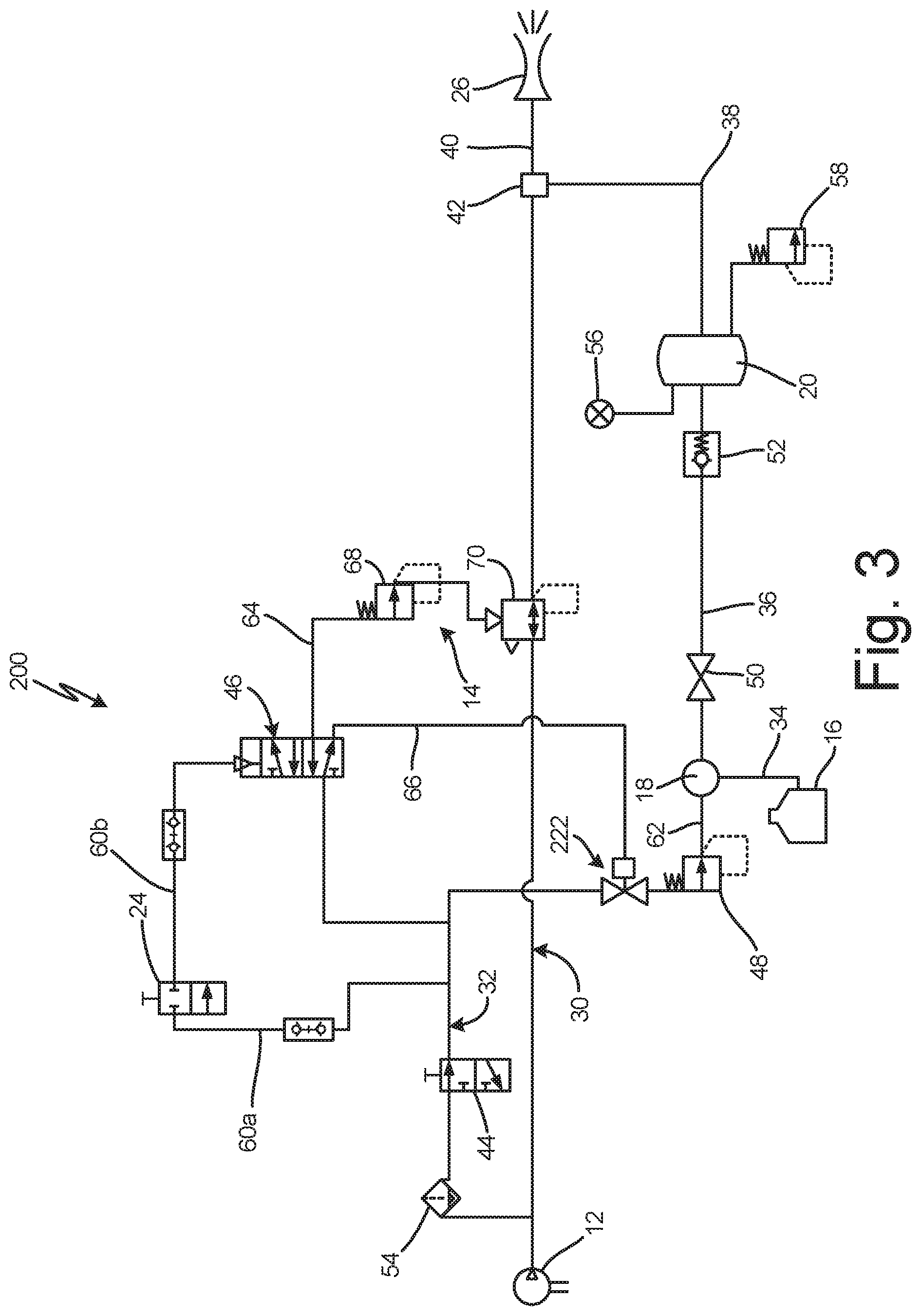
[0009] FIG. 3 is a schematic diagram of a vapor blast system with a control valve configured to control the flow of air to the water pump.
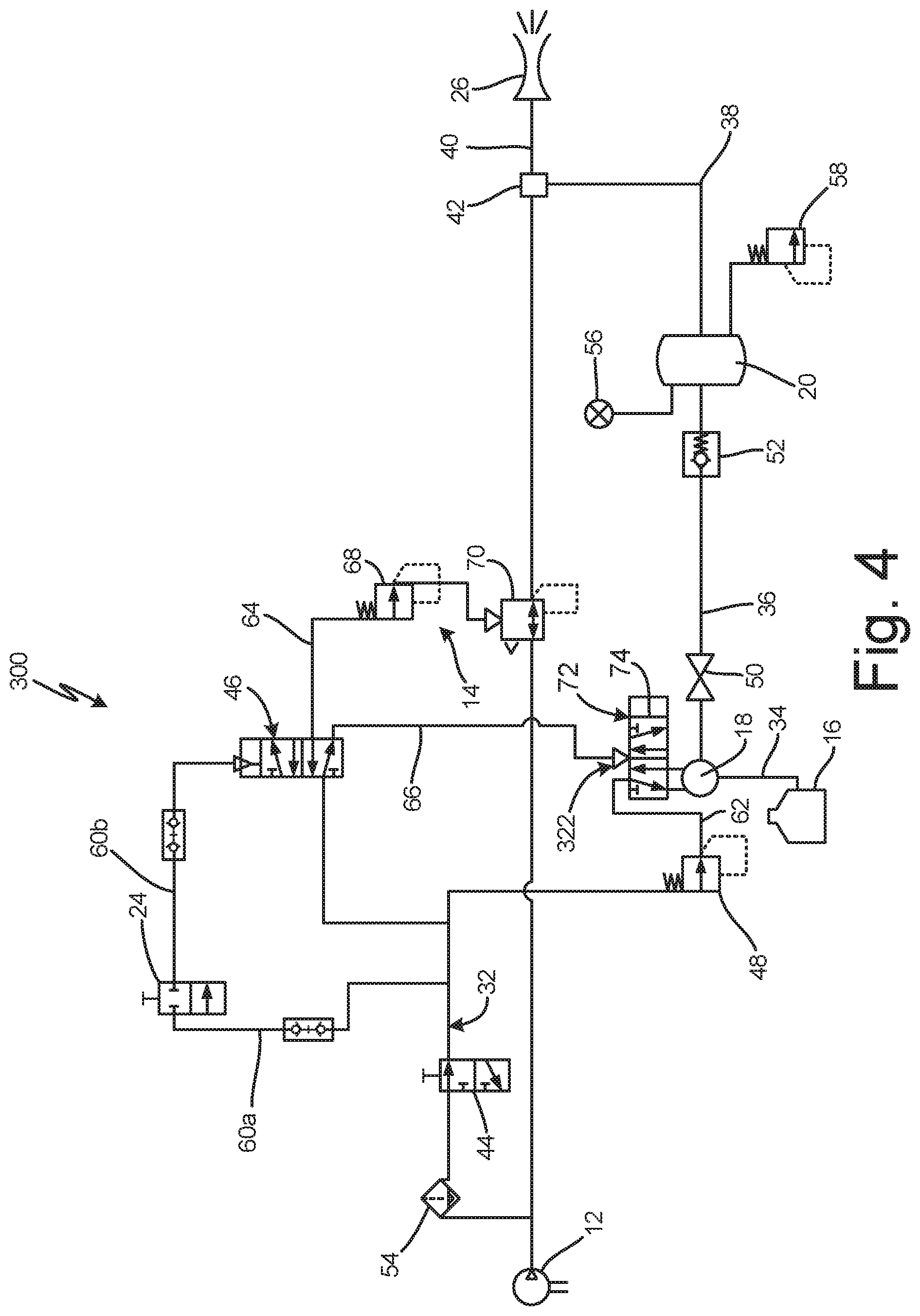
[0010] FIG. 4 is a schematic diagram of a vapor blast system with a control valve configured to control the water pump.
DETAILED DESCRIPTION
[0011] FIG. 1 is a simplified schematic diagram of vapor blast system 10, which is a system that entrains a blast slurry of water and blast media (e.g. garnet, walnut shells, or any other suitable blasting media) in a flow of compressed air to perform coating removal and surface preparation. Vapor blast system 10 includes compressor 12, blast air controller 14, water source 16, water pump 18, pressure pot 20, control valves 22a-22c, blast control switch 24, nozzle 26, control logic 28, communication lines 29, air supply line 30, system line 32, water inlet line 34, pressurization line 36, media line 38, blast line 40, and junction 42.
[0012] Compressor 12 is an air compressor that generates a flow of compressed air to entrain the blast slurry and to power various components of vapor blast system 10. Compressor 12 is configured to generate the flow of compressed air whenever vapor blast system 10 is operating. Air supply line 30 extends from compressor 12 to junction 42. Junction 42 is the location where media line 38 and air supply line 30 join to form blast line 40. Blast line 40 extends from junction 42 of air supply line 30 and media line 38 to nozzle 26. Nozzle 26 ejects a spray of entrained blast slurry for application to a surface.
[0013] System line 32 branches from air supply line 30 upstream of blast air controller 14 and extends to water pump 18. The compressed air from compressor 12 flows into air supply line 30. A blast portion of the compressed air ("blast air") flows downstream through air supply line 30 to nozzle 26, and a system portion of the compressed air ("system air") flows into system line 32. System line 32 provides the system air to water pump 18, and the system air powers water pump 18. Water pump 18 includes a shuttle valve that directs the system air to power reciprocation of the piston of water pump 18. While water pump 18 is described as a pneumatically powered pump, it is understood that water pump 18 can be of any desired configuration, such as an electric pump or a hydraulic pump.
[0014] Blast air controller 14 is disposed on air supply line 30 and is controllable between an open state, in which blast air controller 14 allows the blast portion to flow downstream to junction 42, and a closed state, in which blast air controller 14 prevents the compressed air from flowing downstream to junction 42. Blast air controller 14 is thereby configured to control blasting by controlling the flow of blast air to nozzle 26.
[0015] Water inlet line 34 extends from water source 16 to water pump 18. Pressurization line 36 extends from water pump 18 to pressure pot 20 and supplies the pumped water to pressure pot 20. Water source 16 stores a supply of water that water pump 18 pumps to pressure pot 20 through pressurization line 36. The pumped water pressurizes pressure pot 20 and generates the blast slurry.
[0016] Media line 38 extends from pressure pot 20 to junction 42. Media line 38 conveys the blast slurry from pressure pot 20 to junction 42 where the blast slurry is entrained in the blast air from air supply line 30. The entrained blast slurry is driven out of nozzle 26 by the blast air. Junction 42 is located at a higher elevation than the maximum fill level of pressure pot 20 to prevent the blast media from being gravity fed through media line 38 to blast line 40.
[0017] Control valves 22a-22c are configured to control the flow of pumped water to pressure pot 20 to thereby control the flow of blast slurry out of pressure pot 20. Control valve 22a is disposed on pressurization line 36 between water pump 18 and pressure pot 20. Control valve 22b is disposed on system line 32 upstream of water pump 18. Control valve 22c is disposed on water pump 18. Control valve 22c directly interfaces with water pump 18 and mechanically controls pumping by water pump 18.
[0018] Control valves 22a-22c are controllable between an open state, where control valves 22a-22c allow the pumped water to flow to pressure pot 20, and a closed state, where control valves 22a-22c prevent the pumped water from flowing to pressure pot 20. Control valves 22a-22c are disposed upstream of pressure pot 20 such that control valves 22a-22c do not interface directly with either the blast media or the blast slurry. While vapor blast system 10 is shown as including control valve 22a, control valve 22b, and control valve 22c, it is understood that vapor blast system 10 need include only one of control valve 22a, control valve 22b, and control valve 22c to control the flow of pumped water to pressure pot 20.
[0019] Control valves 22a-22c are of any suitable configuration for controlling the flow of pumped water to pressure pot 20. Control valve 22a is a water valve on pressurization line 36 that controls the flow of pumped water to pressure pot 20. As such, control valve 22a directly controls the flow of pressurized water to pressure pot 20. Control valve 22b is an air valve on system line 32 that controls the flow of system air to water pump 18. Control valve 22b controls the flow of water to pressure pot 20 by controlling activation of water pump 18. Control valve 22c mechanically interfaces with water pump 18 to control the flow of water to pressure pot 20. In some examples, control valve 22c is a mechanical device configured to restrict reciprocation of the shuttle of the shuttle valve that directs the system air within water pump 18 to power water pump 18. For example, control valve 22c can include a pin that control valve 22c extends and retracts to inhibit and allow reciprocation of the shuttle.
[0020] Blast control switch 24 is connected to blast air controller 14 and control valves 22a-22c. Blast control switch 24 controls blast air controller 14 and control valves 22a-22c between their respective open states and closed states. Blast control switch 24 is configured to be switched between an activated state and a deactivated state by the user to control the flow of the entrained blast slurry out of nozzle 26. Blast control switch 24 can communicate with and control blast air controller 14 and control valves 22a-22c in any suitable manner. For example, blast control switch 24 can include a trigger that the user depresses to place blast control switch 24 in the activated state and that the user releases to place blast control switch 24 in the deactivated state.
[0021] Communication lines 29 extend from blast control switch 24 and provide commands to blast air controller 14, control valves 22a-22c, and control logic 28 from blast control switch 24. Communication lines 29 can be of any suitable form for communicating commands from blast control switch 24, such as electronic or pneumatic lines.
[0022] In one example, blast control switch 24 is a pneumatic switch and blast air controller 14 and control valves 22a-22c are pneumatically actuated. In such an example, system line 32 can extend to both blast air controller 14 and control valves 22a-22c to provide compressed air to blast air controller 14 and control valves 22a-22c to actuate blast air controller 14 and control valves 22a-22c between their respective states. Blast control switch 24 directs the flow of compressed air to both blast air controller 14 and control valves 22a-22c to control the respective states of blast air controller 14 and control valves 22a-22c.
[0023] In another example, blast air controller 14 communicates electronically through either wired or wireless communication links, such as communication lines 29, with both blast air controller 14 and control valves 22a-22c. Blast air controller 14 provides an activation signal to blast air controller 14 and control valves 22a-22c to cause blast air controller 14 and control valves 22a-22c to shift to their respective open states. Blast air controller 14 provides a deactivation signal to blast air controller 14 and control valves 22a-22c to cause blast air controller 14 and control valves 22a-22c to shift to their respective closed states.
[0024] Control logic 28 is in communication, via communication lines 29, with blast control switch 24, blast air controller 14, and control valves 22a-22c. Control logic 28 is configured to implement a delay in actuation between blast air controller 14 and control valves 22a-22c. Control logic 28 can be of any suitable configuration for implementing a delay between actuation of blast air controller 14 and control valves 22a-22c. For example, control logic 28 can include any one or more of a microprocessor, a controller, a digital signal processor (DSP), an application specific integrated circuit (ASIC), a field-programmable gate array (FPGA), or other equivalent discrete or integrated logic circuitry. In some examples, control logic 28 is an air logic controller such that compressed air from compressor 12 is the control medium. In each example, control logic 28 is configured to cause blast air controller 14 to shift to the open state prior to control valves 22a-22c shifting to the open state, and to cause blast air controller 14 to shift to the closed state after control valves 22a-22c shift to the closed state. As such, control logic 28 ensures that blast air is flowing through blast line 40 whenever control valves 22a-22c are in the open state, thereby ensuring that the blast slurry flowing out of media line 38 is entrained and carried out of nozzle 26.
[0025] During operation, the user controls the flow of entrained blast slurry out of nozzle 26 via blast control switch 24. Blast air controller 14 and control valves 22 are configured to be in a similar state. As such, both blast air controller 14 and control valve are in the open state when blasting is desired, and both blast air controller 14 and control valve 22 are in the closed state when blasting is not desired.
[0026] When blasting is desired, blast control switch 24 causes both blast air controller 14 and control valves 22a-22c to shift the open state. With blast air controller 14 in the open state the blast air flows through air supply line 30 to junction 42, downstream through blast line 40 and out of nozzle 26. With control valves 22a-22c in the open state the pumped water from water pump 18 flows through pressurization line 36 and into pressure pot 20. The pumped water causes the pressure in pressure pot 20 to rise and the increased pressure drives the blast slurry out of pressure pot through media line 38. The blast slurry flows through media line 38 to junction 42 where the blast slurry is entrained in the blast air and sprayed out of nozzle 26.
[0027] Control valves 22a-22c control the flow of pumped water to pressure pot 20 in different manners. As discussed above, control valve 22a is a water valve configured to directly control the water flow through pressurization line 36. With control valve 22a in the closed state the pumped water from water pump 18 deadheads at control valve 22a. With control valve 22a in the open state, the pumped water flows downstream into pressure pot 20. Control valve 22b is an air valve configured to control the system air flow to water pump 18. With control valve 22b in the closed state the system air cannot flow to water pump 18 to power water pump 18, so water pump 18 does not generate the pressurizing water flow. With control valve 22b in the open state, the system air flows to and powers water pump 18, and water pump 18 pumps the pressurizing water to pressure pot 20. Control valve 22c is a mechanical device interacting with water pump 18 to control activation of water pump 18. With control valve 22c in the closed state, control valve 22c physically inhibits the oscillation of the shuttle of water pump 18, thereby preventing the shuttle from directing the system air that powers water pump 18 such that water pump 18 does not generate the pressuring water flow. With control valve 22c in the open state, the shuttle can oscillate and direct the system air such that water pump 18 pumps the pressurizing water flow to water pump 18.
[0028] In some examples, blast air controller 14 shifts to the open state prior to control valves 22a-22c shifting to the open state. For example, blast control switch 24 can be configured to implement of delay between sending the open command to blast air controller 14 and sending the open command to control valves 22a-22c. Control logic 28 can also implement the delay. Actuating blast air controller 14 to the open state prior to actuating control valves 22a-22c to the open state ensures that the blast air is already flowing through junction 42 and blast line 40 prior to the blast slurry first reaching junction 42. A uniform flow of entrained blast slurry is thereby generated at the beginning of the blast operation.
[0029] The user stops the flow of entrained blast slurry by placing blast control switch 24 in the deactivated state. For example, the user can release the trigger of blast control switch 24. In the deactivated state, blast control switch 24 causes both blast air controller 14 and control valves 22a-22c to shift to their respective closed states. The blast air is prevented from flowing to blast line 40 with blast air controller 14 in the closed state. The pumped water is prevented from flowing to and pressurizing pressure pot 20 with control valves 22 in the closed state. Preventing the pumped water from flowing to pressure pot 20 causes the pressure within pressure pot 20 to decrease as the blast slurry flows out of pressure pot 20 through media line 38. The pressure drops to a sufficiently low level such that the blast slurry is not driven through media line 38 to junction 42 by the pressure level in pressure pot 20. As such, shutting off the flow of pressurizing water to pressure pot 20 also shuts off the flow of blast slurry out of pressure pot 20.
[0030] Blast air controller 14 to shift to the closed state after control valves 22a-22c shift to the closed state. For example, blast control switch 24 can be configured to implement of delay between sending the close command to blast air controller 14 and sending the close command to control valves 22a-22c. Control logic 28 can also implement the delay. Shifting blast air controller 14 to the closed state after shifting control valves 22a-22c to the closed state ensures that the blast air continues to flow through junction 42 and blast line 40 as the pressure drops in pressure pot 20. The blast air carries any excess flow from pressure pot 20 out of nozzle 26, thereby preventing an undesired plug of blast slurry from forming in blast line 40 when blast control switch 24 is placed in the deactivated state.
[0031] Control valves 22a-22c deactivate the flow of blast slurry out of pressure pot 20 without directly interacting with the blast slurry or the blast media. Instead, control valves 22a-22c directly interface with the flow of pressurizing water, the flow of system air to water pump 18, or mechanically with water pump 18. Controlling the flow of blast slurry by controlling the flow of pumped water to pressure pot 20 prevents control valves 22a-22c from experiencing wear caused by directly interfacing with the blast slurry. Vapor blast system 10 does not require any valve in the direct flow of blast media, on either the media line 38 or the blast line 40. Blasting media flow is instead controlled entirely by controlling the flow of water into pressure pot 20. Eliminating valves in the flowpath of the blast media reduces maintenance requirements for vapor blast system 10, thereby reducing maintenance costs and downtime. In addition, positioning junction 42 at a higher elevation than the maximum fill level of pressure pot 20 prevents any undesired flow of blast slurry out of media line 38 to junction 42 when the blast air flow is stopped.
[0032] Control logic 28 also increases efficiency and provides increased spray quality. Control logic 28 ensures that the blast air begins flowing to blast line 40 prior to the blast slurry flowing to blast line 40, and that the blast air continues to flow to blast line 40 after the blast slurry stops flowing to blast line 40. Delaying the flow of blast slurry to blast line 40 until after blast air is flowing to blast line 40 ensures an even high-quality spray of entrained blast slurry at nozzle 26 as blasting begins. Delaying cessation of the flow of blast air to blast line 40 until after the blast slurry stops flowing to blast line 40 prevents undesired accumulation of blast media in blast line 40, which can lead to accumulation of blast slurry in blast line 40 that can obstruct the flow of material and air and can cause undesired spray qualities when blasting is reinitiated.
[0033] FIG. 2 is a schematic diagram of vapor blast system 100, which includes compressor 12, blast air controller 14, water source 16, water pump 18, pressure pot 20, blast control switch 24, nozzle 26, air supply line 30, system line 32, water inlet line 34, pressurization line 36, media line 38, blast line 40, junction 42, disconnect 44, system valve 46, pump pressure regulator 48, flow valve 50, check valve 52, air filter 54, pressure gauge 56, pressure relief 58, system control line 60a, system control line 60b, pump control line 62, blast control line 64, pressure control line 66, and control valve 122. Blast air controller 14 includes air pressure regulator 68 and blast air regulator 70.
[0034] Compressor 12 is an air compressor configured to generate a flow of compressed air and to provide the flow of compressed air to air supply line 30. The compressed air splits as it flows through air supply line 30. Water pump 18 is configured to draw water from water source 16 and pump the water downstream to pressure pot 20 to pressurize pressure pot 20. Pressure pot 20 stores a blast slurry comprised of water and abrasive blasting media. The pressure within pressure pot 20 causes the blast slurry to flow downstream from pressure pot 20 through media line 38 and to blast line 40, where the blast slurry is entrained in the blast air flowing through air supply line 30. The entrained blast slurry is conveyed downstream to nozzle 26 and is sprayed from nozzle 26 and applied to the desired blast surface.
[0035] Air supply line 30 extends from compressor 12 to blast line 40. System line 32 branches off of air supply line 30 and receives a portion of the compressed air flow from air supply line 30. A blast portion of the compressed air ("blast air") flows downstream through air supply line 30 and a system portion of the compressed air ("system air") flows through system line 32.
[0036] Blast air controller 14 controls the flow of the blast air through air supply line 30. Blast air regulator 70 is disposed on air supply line 30 and controls the flow of blast air downstream through air supply line 30. Blast air regulator 70 is positionable at any desired position between a fully open position, allowing a maximum flow of blast air through air supply line 30, and a fully closed position, preventing any air from flowing downstream through air supply line 30. Blast air regulator 70 is normally-closed and is actuated to the open state by the system air when blasting is desired. Air pressure regulator 68 controls the flow of system air to blast air regulator 70, and the pressure provided by the system air determines the degree that blast air regulator 70 opens. The user controls the blast air pressure via air pressure regulator 68. As such, air pressure regulator 68 controls the flow of system air to blast air regulator 70, and blast air regulator 70 controls the flow of blast air through air supply line 30.
[0037] Air filter 54 is disposed on system line 32 and is configured to remove contaminants from the compressed air flowing in system line 32. Disconnect 44 is disposed on system line 32. Disconnect 44 is a flow control valve that controls the flow of compressed air into system line 32, and in some examples provides an emergency stop for vapor blast system 100. With disconnect 44 in an open state, the compressed air in system line 32 can flow downstream through disconnect 44 to power and control various components of vapor blast system 100. With disconnect 44 in a closed state, the compressed air in system line 32 cannot flow downstream past disconnect 44 to power the components of vapor blast system 100 and vapor blast system 100 is thereby prevented from blasting.
[0038] System line 32 extends downstream from disconnect 44 to system valve 46 and pump pressure regulator 48. Pump control line 62 is a portion of system line 32 that extends from pump pressure regulator 48 to water pump 18. Pump pressure regulator 48 controls the flow of system air to water pump 18 to thereby control the speed of and the pressure generated by water pump 18. Water pump 18 is configured to draw water from water source 16 through water inlet line 34 and to pump the water downstream to pressurization line 36. Flow valve 50 is disposed on pressurization line 36 and is configured to regulate the flow rate of water from water pump 18 to pressure pot 20. Flow valve 50 can be of any suitable form for regulating the water flow, such as one or more needle valves. The user sets the position of internal components of flow valve 50 to set the flow rate of the pressurizing water flowing to pressure pot 20. The flow rate of the pressurizing water to pressure pot 20 is directly related to the flow rate of the blast slurry out of pressure pot 20, such that the flow rate of the blast slurry is controlled by controlling the flow through flow valve 50. Check valve 52 is disposed on pressurization line 36 between control valve 122 and pressure pot 20. Check valve 52 prevents water and media from backflowing out of pressure pot 20 to pressurization line 36.
[0039] Control valve 122 is disposed on pressurization line 36 between water pump 18 and pressure pot 20. Control valve 122 is controllable between an open state, where the pumped water can flow downstream through control valve 122 to pressure pot 20, and a closed state, where the pumped water is prevented from flowing to pressure pot 20. Control valve 122 is a normally-open valve such that control valve 122 remains in the open state unless actuated to the closed state. Control valve 122 can be any suitable valve for controlling the flow of water through pressurization line 36, such as a ball valve, a pinch valve, a disk valve, a gate valve, or any other suitable valve. Control valve 122 controls the pressurization of pressure pot 20, thereby controlling the flow of blast slurry out of pressure pot 20.
[0040] Pressure pot 20 is a pressure vessel configured to store the blast slurry. Pressure gauge 56 is configured to provide an indication of the pressure level in pressure pot 20 to the user. Pressure relief 58 is a valve that allows the user to relieve the pressure within pressure pot 20 prior to opening pressure pot 20. Media line 38 extends downstream from pressure pot 20 and merges with air supply line 30 at junction 42. Media line 38 provides the blast slurry from pressure pot 20 to junction 42, where the blast slurry is entrained in the blast air flowing through air supply line 30. Blast line 40 extends from junction 42 to nozzle 26 and conveys the entrained blast slurry to nozzle 26. Nozzle 26 is open and, in some examples, does not contain any internal mechanism for controlling the flow of entrained blast slurry out of nozzle 26.
[0041] Media line 38 is open between pressure pot 20 and blast line 40, and no valve is disposed on media line 38 to control the flow of blast slurry through media line 38. Instead, the flow of blast slurry through media line 38 is controlled by the pressure in pressure pot 20. Junction 42 of media line 38 and air supply line 30 is located at a higher elevation than the maximum fill level of pressure pot 20 to prevent the blast slurry from being gravity fed from pressure pot 20 to blast line 40 when blasting is not desired. In addition, media line 38 is preferably rigid, which further prevents accumulation of the blast slurry in media line 38 when vapor blast system 100 is deactivated.
[0042] System control line 60a branches off of system line 32 and extends to blast control switch 24. System control line 60b extends from blast control switch 24 to system valve 46. A control portion of the compressed air from compressor 12 flows into system control line 60a. Blast control switch 24 is controllable between an activated state, where the control air can flow from system control line 60a to system control line 60b through blast control switch 24, and a deactivated state, where system control line 60a is disconnected from system control line 60b to prevent the control air from flowing from system control line 60a to system control line 60b. In some examples, blast control switch 24 is integrated with or closely located to nozzle 26 such that the same user can actuate blast control switch 24 and aim nozzle 26. For example, blast control switch 24 can be actuated between the activated state and the deactivated state by the user depressing a trigger of blast control switch 24.
[0043] While blast control switch 24 is described as a pneumatic controller, it is understood that blast control switch 24 can be of any desired form for controlling the state of system valve 46. For example, blast control switch 24 can communicate electronically, though either a wired or wireless connection, with system valve 46 to control the state of system valve 46. In some examples, blast control switch 24 can directly communicate with blast air controller 14 and control valve 122 to control the respective states of blast air controller 14 and control valve 122. For example, each of blast air controller 14 and control valve 122 can be electrically actuated by a solenoid valve, and blast air controller 14 can provide electrical signals to the respective solenoid valves to actuate blast air controller 14 and control valve 122 between the open and closed states.
[0044] Blast control line 64 and pressure control line 66 extend downstream from system valve 46. Blast control line 64 extends to air pressure regulator 68 and from air pressure regulator 68 to blast air regulator 70. Pressure control line 66 extends to control valve 122. System valve 46 directs the flow of system air to either blast control line 64 or pressure control line 66 depending on the state of system valve 46. System valve 46 directs the system air to blast control line 64 and away from pressure control line 66 when system valve 46 is in a system-on state. Directing the system air to blast control line 64 causes blast air regulator 70 to shift to the open state and causes control valve 122 to return to the open state, as control valve 122 is normally-open. System valve 46 directs the system air to pressure control line 66 and away from blast control line 64 when system valve 46 is in a system-off state. Directing the system air to pressure control line 66 causes control valve 122 to shift to the closed state and blast air regulator 70 to return to the closed state, as blast air regulator 70 is normally-closed.
[0045] During operation, compressor 12 is activated and generates and provides a compressed air flow to air supply line 30. The user places vapor blast system 100 in operation by shifting disconnect 44 to the open state such that the system portion can flow downstream from disconnect 44 through system line 32. The blast air portion flows downstream through air supply line 30 towards blast line 40. The system air flows through system line 32 to system valve 46 and water pump 18. The control air flows to blast control switch 24 through system control line 60a. Blast control switch 24 is normally-closed such that blast control switch 24 prevents the control air from flowing to system valve 46 through system control line 60b.
[0046] The system air flowing to pump control line 62 initially flows through pump pressure regulator 48, which can be set at any desired position by the user to control the water pressure generated by water pump 18. The system air flows to and powers water pump 18. Water pump 18 draws water from water source 16 through water inlet line 34 and pumps the water downstream through pressurization line 36. The water flows through flow valve 50, which limits the flow rate of the water to thereby limiting the flow rate of the blast slurry leaving pressure pot 20, and to pressure pot 20 through pressurization line 36. Control valve 122 is disposed on pressurization line 36 and controls the flow of water to pressure pot 20. With control valve 122 in the closed state, the water deadheads at control valve 122 and does not flow to pressure pot 20.
[0047] System valve 46 is in the system-off state until blast control switch 24 is actuated to an activated state, where system control line 60a is connected to system control line 60b. In the system-off state system valve 46 directs the system air to pressure control line 66. The system air flows through pressure control line 66 to control valve 122 and causes control valve to shift to and remain in the closed state. In the closed state control valve 122 prevents the water pumped into pressurization line 36 from flowing to pressure pot 20. As such, pressure pot 20 is not pressurized by the water and the blast slurry does not flow out of pressure pot 20 to media line 38. In the system-off state system valve 46 prevents the system air from flowing to blast control line 64. Blast air regulator 70 thus remains in the normally-closed state and prevents the blast air from flowing downstream through air supply line 30. As such, with blast control switch 24 in the deactivated state, both blast air regulator 70 and control valve 122 are in their respective closed states.
[0048] To initiate blasting, the user actuates blast control switch 24 to an activated state where system control line 60a is fluidly connected to system control line 60b such that the control air flows to system control line 60b. System control line 60b provides the control air to system valve 46, where the control air causes system valve 46 to shift to the system-on state. In the system-on state system valve 46 directs the system air to blast control line 64 and prevents the system air from flowing to pressure control line 66. The system air flows through blast control line 64 to blast air regulator 70, where the system air causes blast air regulator 70 to shift to the open state. With blast air regulator 70 in the open state the blast air flows downstream through air supply line 30 past blast air regulator 70 and to blast line 40. Without the system air to maintain control valve 122 in the closed state, control valve 122 returns to the normally-open state. As such, both blast air regulator 70 and control valve 122 are open with blast control switch 24 in the activated state.
[0049] With control valve 122 in the open state the pumped water from water pump 18 flows through pressurization line 36 to pressure pot 20. The pumped water pressurizes pressure pot 20, and the increased pressure within pressure pot 20 drives the blast slurry out of pressure pot 20 and downstream through media line 38 to junction 42. The blast slurry is entrained in the blast portion of air at junction 42, and the entrained blast slurry is driven downstream through blast line 40 and out of nozzle 26.
[0050] To stop blasting the user returns blast control switch 24 to the deactivated state, such as by releasing the trigger of blast control switch 24. In the deactivated state blast control switch 24 prevents the control air from flowing to system control line 60b from system control line 60a. System valve 46 returns to the system-off state. In the system-off state system valve 46 prevents the system air from flowing to blast air regulator 70 through blast control line 64, such that blast air regulator 70 returns to the normally-closed position, and directs the system air to control valve 122 through pressure control line 66, such that control valve 122 shifts to the closed state. Control valve 122 prevents the water from flowing to and pressurizing pressure pot 20 when in the closed state. Without a flow of pressurizing water the pressure in pressure pot 20 drops. The decreased pressure at an insufficient level to drive the blast slurry downstream through media line 38. Blasting is thus ceased by ceasing the flow of water to pressure pot 20.
[0051] Vapor blast system 100 includes logic, such as control logic 28 (FIG. 1), to prevent undesired accumulation of blast media in blast line 40. When system valve 46 shifts to the system-on position, the logic ensures that blast air regulator 70 shifts to the open position prior to control valve 122 shifting to the open position. As such, the blast air flows to and through blast line 40 prior to the blast slurry beginning to flow to blast line 40. Flowing the blast air through blast line 40 prior to introducing the blast slurry prevents undesired buildup of blast slurry in blast line 40 and ensures a smooth, high-quality flow of the entrained blast slurry out of nozzle 26. When system valve 46 shifts to the system-off state, the logic ensures that control valve 122 shifts to the closed state prior to blast air regulator 70 shifting to the closed state. Shifting control valve 122 to the closed state prior to shifting blast air regulator 70 to the closed state ensures that the blast air continues to flow to blast line 40 as pressure pot 20 depressurizes, thereby preventing undesired accumulation of blast slurry in blast line 40.
[0052] Vapor blast system 100 provides significant advantages. Control valve 122 is disposed upstream of pressure pot 20 and controls the flow of pressurizing water to pressure pot 20. Controlling the flow of pressurizing water to pressure pot 20 controls pressurization of pressure pot 20 and thus controls the flow of blast slurry out of pressure pot 20. There are no valves disposed downstream of pressure pot 20. Blasting is instead controlled directly by controlling the pressurization of pressure pot 20. Eliminating valves downstream of pressure pot 20 in the flowpath of the blast media reduces maintenance requirements for vapor blast system 100, thereby reducing maintenance costs and downtime. In addition, positioning junction 42 at a higher elevation than the maximum fill level of pressure pot 20 prevents undesired flow of blast slurry out of media line 38. The control logic ensures that the blast air begins flowing through blast line 40 prior to the blast slurry flowing to blast line 40 and that the blast air continues to flow through blast line 40 as pressure pot 20 depressurizes, which eliminates clogging and undesired accumulation of blast slurry in blast line 40.
[0053] FIG. 3 is a schematic diagram of vapor blast system 200. Vapor blast system 200 includes compressor 12, blast air controller 14, water source 16, water pump 18, pressure pot 20, blast control switch 24, nozzle 26, air supply line 30, system line 32, water inlet line 34, pressurization line 36, media line 38, blast line 40, junction 42, disconnect 44, system valve 46, pump pressure regulator 48, flow valve 50, check valve 52, air filter 54, pressure gauge 56, pressure relief 58, system control line 60a, system control line 60b, pump control line 62, blast control line 64, pressure control line 66, and control valve 222. Blast air controller 14 includes air pressure regulator 68 and blast air regulator 70.
[0054] Vapor blast system 200 is substantially similar to vapor blast system 10 shown in FIG. 1 and vapor blast system 100 shown in FIG. 2, except control valve 222 is located on system line 32 upstream of water pump 18, similar to control valve 22b (FIG. 1). While control valve 222 is shown as disposed upstream of pump pressure regulator 48, it is understood that control valve 222 can disposed at any desired location for controlling the system air flow to water pump 18, such as on pump control line 62 between pump pressure regulator 48 and water pump 18.
[0055] Pressure control line 66 extends from system valve 46 to control valve 222. Control valve 222 controls the flow of system air to water pump 18. Control valve 222 is a normally-open valve that shifts to the closed state when system valve 46 is in the system-off state. Control valve 222 returns to the open state when system valve 46 is in the system-on state such that system valve 46 directs the system air to blast control line 64.
[0056] Control valve 222 is controlled between the open state and the closed state to control pressurization of pressure pot 20. Actuating control valve 222 to the closed state stops the flow of system air to water pump 18, thereby deactivating water pump 18. Deactivating water pump 18 prevents water pump 18 from pumping water to pressure pot 20 through pressurization line 36, thereby allowing the pressure in pressure pot 20 to drop. The decreased pressure in pressure pot 20 is sufficiently low such that the pressure does not drive the blast slurry downstream to blast line 40 through media line 38. Pressure pot 20 remains at the decreased pressure and the blast slurry remains in pressure pot 20 until control valve 222 shifts to the open state.
[0057] System valve 46 causes control valve 222 to shift to the open state when system valve 46 is in the system-on state. In the open state, control valve 222 allows the system air to flow to and power water pump 18. Water pump 18 draws water from water source 16 and pumps the water to pressure pot 20 through pressurization line 36. The pumped water increases the pressure in pressure pot 20, and the increased pressure drives the blast slurry downstream out of pressure pot 20 through media line 38 to junction 42, where the blast slurry is entrained in the blast air and driven downstream though blast line 40 and out of nozzle 26.
[0058] Vapor blast system 200 includes logic, such as control logic 28 (FIG. 1), to prevent accumulation of the blast slurry in blast line 40. When system valve 46 shifts to the system-on state, the logic ensures that blast air regulator 70 shifts to the open state prior to control valve 222 shifting to the open state. When system valve 46 shifts to the system-off state, the logic ensures that control valve 222 shifts to the closed state prior to blast air regulator 70 shifting to the closed state.
[0059] Vapor blast system 200 and control valve 222 provide significant advantages. Control valve 222 controls the flow of system air to water pump 18 to control the flow of blast slurry out of pressure pot 20. Control valve 222 deactivates water pump 18 by shutting off the flow of system air to water pump 18. Control valve 222 interfaces with only the system air and is not subject to the wear generated by interacting with the blast media in the blast slurry, thereby reducing maintenance and replacement costs and simplifying vapor blast system 200.
[0060] FIG. 4 is a schematic diagram of vapor blast system 300. Vapor blast system 210 includes compressor 12, blast air controller 14, water source 16, water pump 18, pressure pot 20, blast control switch 24, nozzle 26, air supply line 30, system line 32, water inlet line 34, pressurization line 36, media line 38, blast line 40, junction 42, disconnect 44, system valve 46, pump pressure regulator 48, flow valve 50, check valve 52, air filter 54, pressure gauge 56, pressure relief 58, system control line 60a, system control line 60b, pump control line 62, blast control line 64, pressure control line 66, and control valve 322. Blast air controller 14 includes air pressure regulator 68 and blast air regulator 70. Water pump 18 includes shuttle valve 72, and shuttle valve 72 includes shuttle member 74.
[0061] Vapor blast system 300 is substantially similar to vapor blast system 10 shown in FIG. 1, vapor blast system 100 shown in FIG. 2, and vapor blast system 200 shown in FIG. 3, except control valve 322 of vapor blast system 300 mechanically interacts with water pump 18 to control the flow of pressurizing water to pressure pot 20, similar to control valve 22c (FIG. 1).
[0062] Pressure control line 66 extends from system valve 46 to control valve 322. Water pump 18 includes shuttle valve 72 that includes a reciprocating shuttle member that directs the system air received from pump control line 62 to power water pump 18. Control valve 322 inhibits reciprocation of the shuttle member 74 of shuttle valve 72 when in the closed state to prevent water pump 18 from pumping water to pressure pot 20. For example, control valve 322 can be configured to extend a pin into shuttle valve 72 to mechanically inhibit reciprocation of shuttle member 74. With control valve 322 in the open position, shuttle member 74 is free to reciprocate and direct the flow of system air to power water pump 18.
[0063] Control valve 322 is normally-open and shifts to the closed state when system valve 46 is in the system-off state and is directing the system air through pressure control line 66. Control valve 322 returns to the open state when system valve 46 is in the system-on state and is directing the system air to blast control line 64.
[0064] Control valve 322 is controlled between the open state and the closed state to control pressurization of pressure pot 20. Actuating control valve 322 to the closed state deactivates water pump 18. Deactivating water pump 18 prevents water pump 18 from pumping water to pressure pot 20 through pressurization line 36, thereby allowing the pressure in pressure pot 20 to drop. The decreased pressure in pressure pot 20 is sufficiently low such that the pressure does not drive the blast slurry downstream to blast line 40 through media line 38. Pressure pot 20 remains at the decreased pressure and the blast slurry remains in pressure pot 20 until control valve 322 shifts to the open state and water pump 18 pumps water to pressure pot 20.
[0065] Control valve 322 shifts to the open state when system valve 46 is in the system-on state and is directing the system air to blast control line 64. In the open state, control valve 322 allows shuttle member 74 to reciprocate to direct the system air within water pump 18 to power water pump 18. Water pump 18 draws water from water source 16 and pumps the water to pressure pot 20 through pressurization line 36. The pumped water increases the pressure in pressure pot 20, and the increased pressure drives the blast slurry out of pressure pot 20 to media line 38, and downstream through media line 38 to blast line 40.
[0066] Vapor blast system 300 includes logic, such as control logic 28 (FIG. 1), to prevent undesired accumulation of the blast slurry in blast line 40. When system valve 46 shifts to the system-on state, the logic ensures that blast air regulator 70 shifts to the open state prior to control valve 322 shifting to the open state. When system valve 46 shifts to the system-off state, the logic ensures that control valve 322 shifts to the closed state prior to blast air regulator 70 shifting to the closed state.
[0067] Vapor blast system 300 and control valve 322 provide significant advantages.
[0068] Control valve 322 controls the flow of system air to water pump 18 to control the flow of blast slurry out of pressure pot 20. Control valve 322 deactivates water pump 18 by mechanically deactivating water pump 18. Control valve 322 interfaces with only the mechanical components of water pump 18 and is therefore not subject to the wear generated by interacting with the blast media in the blast slurry. Preventing wear to control valve reduces maintenance and replacement costs and simplifies vapor blast system 300.
[0069] Although the present invention has been described with reference to preferred embodiments, workers skilled in the art will recognize that changes may be made in form and detail without departing from the spirit and scope of the invention.
* * * * *
D00000
D00001
D00002
D00003
D00004
XML
uspto.report is an independent third-party trademark research tool that is not affiliated, endorsed, or sponsored by the United States Patent and Trademark Office (USPTO) or any other governmental organization. The information provided by uspto.report is based on publicly available data at the time of writing and is intended for informational purposes only.
While we strive to provide accurate and up-to-date information, we do not guarantee the accuracy, completeness, reliability, or suitability of the information displayed on this site. The use of this site is at your own risk. Any reliance you place on such information is therefore strictly at your own risk.
All official trademark data, including owner information, should be verified by visiting the official USPTO website at www.uspto.gov. This site is not intended to replace professional legal advice and should not be used as a substitute for consulting with a legal professional who is knowledgeable about trademark law.