Additive Manufactured Conglomerated Powder Removal From Internal Passages
Oswald; Caitlin ; et al.
U.S. patent application number 16/695877 was filed with the patent office on 2020-03-26 for additive manufactured conglomerated powder removal from internal passages. This patent application is currently assigned to United Technologies Corporation. The applicant listed for this patent is United Technologies Corporation. Invention is credited to Krzysztof Barnat, Jesse R. Boyer, Caitlin Oswald, Monica C. Smith, Wendell V. Twelves, JR..
| Application Number | 20200094326 16/695877 |
| Document ID | / |
| Family ID | 58192049 |
| Filed Date | 2020-03-26 |


| United States Patent Application | 20200094326 |
| Kind Code | A1 |
| Oswald; Caitlin ; et al. | March 26, 2020 |
ADDITIVE MANUFACTURED CONGLOMERATED POWDER REMOVAL FROM INTERNAL PASSAGES
Abstract
A component includes an additively manufactured component with an internal passage; and an additively manufactured elongated member within the internal passage. A method of additively manufacturing a component including additively manufacturing a component with an internal passage; and additively manufacturing an elongated member within the internal passage concurrent with additively manufacturing the component.
| Inventors: | Oswald; Caitlin; (Ellington, CT) ; Boyer; Jesse R.; (Middletown, CT) ; Twelves, JR.; Wendell V.; (Glastonbury, CT) ; Smith; Monica C.; (West Hartford, CT) ; Barnat; Krzysztof; (Berlin, CT) | ||||||||||
| Applicant: |
|
||||||||||
|---|---|---|---|---|---|---|---|---|---|---|---|
| Assignee: | United Technologies
Corporation Farmington CT |
||||||||||
| Family ID: | 58192049 | ||||||||||
| Appl. No.: | 16/695877 | ||||||||||
| Filed: | November 26, 2019 |
Related U.S. Patent Documents
| Application Number | Filing Date | Patent Number | ||
|---|---|---|---|---|
| 15011959 | Feb 1, 2016 | |||
| 16695877 | ||||
| Current U.S. Class: | 1/1 |
| Current CPC Class: | B08B 9/00 20130101; B22F 2999/00 20130101; B22F 5/106 20130101; B22F 2998/10 20130101; B23K 26/70 20151001; Y02P 10/295 20151101; B22F 5/009 20130101; B33Y 40/00 20141201; B22F 3/1055 20130101; B22F 3/24 20130101; B33Y 10/00 20141201; B22F 2003/247 20130101; B28B 1/001 20130101; B23K 15/0086 20130101; Y02P 10/25 20151101; B23K 26/342 20151001; B33Y 80/00 20141201; B08B 2209/005 20130101; B23K 2101/10 20180801; B22F 2003/1059 20130101; F16L 9/02 20130101; B33Y 70/00 20141201; B22F 2998/10 20130101; B22F 3/1055 20130101; B22F 3/24 20130101; B22F 2999/00 20130101; B22F 3/24 20130101; B22F 2202/01 20130101; B22F 2998/10 20130101; B22F 3/1055 20130101; B22F 2003/247 20130101; B22F 2999/00 20130101; B22F 2003/247 20130101; B22F 2003/1059 20130101; B22F 2202/01 20130101 |
| International Class: | B22F 3/24 20060101 B22F003/24; B22F 5/00 20060101 B22F005/00; B08B 9/00 20060101 B08B009/00; F16L 9/02 20060101 F16L009/02; B28B 1/00 20060101 B28B001/00; B23K 15/00 20060101 B23K015/00; B22F 5/10 20060101 B22F005/10; B22F 3/105 20060101 B22F003/105; B23K 26/70 20060101 B23K026/70; B23K 26/342 20060101 B23K026/342; B33Y 80/00 20060101 B33Y080/00; B33Y 70/00 20060101 B33Y070/00; B33Y 40/00 20060101 B33Y040/00; B33Y 10/00 20060101 B33Y010/00 |
Claims
1-17. (canceled)
18. A component, comprising: an additively manufactured component with a non-line of sight internal passage; and a multiple of agitators additively manufactured within the non-line of sight internal passage.
19. The component as recited in claim 18, wherein the additively manufactured component includes a first flange, a second flange, and a conduit with the internal passage therebetween.
20. The component as recited in claim 19, wherein the conduit includes multiple bends.
21. The component as recited in claim 18, wherein each of the multiple of agitators are spherical.
22. A method of additively manufacturing a component, comprising: vibrating a component at a particular known natural frequency of a multiple of agitators within a non-line of sight internal passage of an additively manufactured component to clean the internal passage of conglomerated powder with the multiple of agitators subsequent to completion of the additively manufacturing of the additively manufactured component.
23. The method as recited in claim 22, further comprising mechanically working the conglomerated powder out of the internal passage with the multiple of agitators.
24. The method as recited in claim 22, further comprising breaking up the conglomerated powder out of the internal passage with the multiple of agitators.
25. The method as recited in claim 22, further comprising fixing the component then vibrating the component to a natural frequency which will excite the agitators such that the agitators vibrate with a force that will break conglomerated powder bonds surrounding each of the multiple of agitators.
26. A method of additively manufacturing a component, comprising: additively manufacturing a component with a non-line of sight internal passage; additively manufacturing a multiple of agitators within the internal passage concurrent with additively manufacturing the component; and fixing the component then vibrating the component to a natural frequency which will excite the agitators such that the agitators begin to vibrate with a force that will break the semi-sintered conglomerated powder bonds surrounding each of the multiple of agitators.
27. The component as recited in claim 26, wherein each of the multiple of agitators clean the internal passage of conglomerated powder subsequent to completion of the additively manufacturing of the additively manufactured component.
Description
CROSS-REFERENCE TO RELATED APPLICATIONS
[0001] This application is a continuation of U.S. patent application Ser. No. 15/011,959 filed Feb. 1, 2016.
BACKGROUND
[0002] The present disclosure relates to additive manufacturing and, more particularly, to removing conglomerated powder from within an internal passage.
[0003] Precision engineered parts such as gas turbine components may be manufactured by an additive manufacturing operation such that features associated with conventional manufacturing processes, e.g., machining, forging, welding, casting, etc. can be eliminated to facilitate savings in cost, material, and time. Additive manufacturing often results in conglomerated powder building-up around, and within, the completed component as an artifact of the process. When additive manufacturing a component that has internal passages, this conglomerated powder often becomes entrapped in the internal passages and is difficult to remove.
[0004] There are currently few methods that directly and rapidly remove the conglomerated powder. One standard practice may include repeated use of an accelerated media blast, combined with mechanically scraping. Another standard practice includes, mega sonic or ultrasonic vibratory methods to liberate the powder particles. Oftentimes, such practices are still inefficient at removal of removing conglomerated powder from within the internal passages.
SUMMARY
[0005] A component according to one disclosed non-limiting embodiment of the present disclosure includes an additively manufactured component with a non-line of sight internal passage; and a multiple of agitators additively manufactured within the non-line of sight internal passage.
[0006] A further aspect of the present disclosure includes that the additively manufactured component include a first flange, a second flange, and a conduit with the internal passage therebetween.
[0007] A further aspect of the present disclosure includes that the conduit includes multiple bends.
[0008] A further aspect of the present disclosure includes that each of the multiple of agitators are spherical.
[0009] A method of additively manufacturing a component according to one disclosed non-limiting embodiment of the present disclosure includes vibrating a component at a particular known natural frequency of a multiple of agitators within a non-line of sight internal passage of an additively manufactured component to clean the internal passage of conglomerated powder with the multiple of agitators subsequent to completion of the additively manufacturing of the additively manufactured component.
[0010] A further aspect of the present disclosure includes mechanically working the conglomerated powder out of the internal passage with the multiple of agitators.
[0011] A further aspect of the present disclosure includes breaking up the conglomerated powder out of the internal passage with the multiple of agitators.
[0012] A further aspect of the present disclosure includes fixing the component then vibrating the component to a natural frequency which will excite the agitators such that the agitators vibrate with a force that will breaking conglomerated powder bonds surrounding each of the multiple of agitators.
[0013] A method of additively manufacturing a component according to one disclosed non-limiting embodiment of the present disclosure includes additively manufacturing a component with a non-line of sight internal passage; and additively manufacturing a multiple of agitators within the internal passage concurrent with additively manufacturing the component; fixing the component then vibrating the component to a natural frequency which will excite the agitators such that the agitators begin to vibrate with a force that will break the semi-sintered conglomerated powder bonds surrounding each of the multiple of agitators.
[0014] A further aspect of the present disclosure includes that each of the multiple of agitators to clean the internal passage of conglomerated powder subsequent to completion of the additively manufacturing of the additively manufactured component.
[0015] The foregoing features and elements may be combined in various combinations without exclusivity, unless expressly indicated otherwise. These features and elements as well as the operation thereof will become more apparent in light of the following description and the accompanying drawings. It should be understood, however, the following description and drawings are intended to be exemplary in nature and non-limiting.
BRIEF DESCRIPTION OF THE DRAWINGS
[0016] Various features will become apparent to those skilled in the art from the following detailed description of the disclosed non-limiting embodiment. The components in the drawings are not necessarily to scale. Moreover, in the drawings, like reference numerals designate corresponding parts throughout the several views. The drawings that accompany the detailed description can be briefly described as follows:
[0017] FIG. 1 is a perspective view of a representative additively manufactured component.
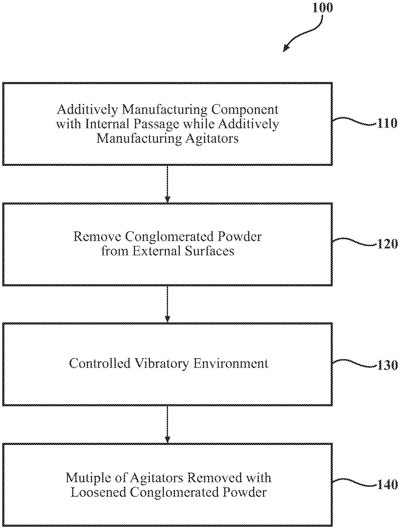
[0018] FIG. 2 is a method of additively manufacturing a component according to one disclosed non-limiting embodiment.
[0019] FIG. 3 is a perspective view of the additively manufactured component of FIG. 1 with a multiple of agitators for removing conglomerated powder from within an internal passage.
[0020] FIG. 4 is a perspective view of the additively manufactured component of FIG. 1 with a multiple of solid agitators.
[0021] FIG. 5 is a perspective view of the additively manufactured component of FIG. 1 with a multiple of open agitators.
[0022] FIG. 6 is a perspective view of the additively manufactured component with the conglomerated powder.
[0023] FIG. 7 is a perspective view of the multiple of agitators within the semi-sintered powder.
[0024] FIG. 8 is a perspective view of the multiple of agitators that have loosened the semi-sintered powder.
DETAILED DESCRIPTION
[0025] FIG. 1 schematically illustrates a component 20 that includes an internal passage 22. In this example, the component 20 may be a conduit such as that of a manifold, duct, flow passage, or other such component. The component 20 may include a first flange 24, a second flange 26, and a conduit 28 with the internal passage 22 therebetween. The internal passage 22 may be complex and be of a non-line of sight geometry that includes multiple bends. It should be appreciated that various additional or alternative segments and/or fittings may also be provided. It should be further appreciated that although a conduit type example is illustrated herein, other aerospace components, aircraft structures, as well as a wide variety of applications outside the aerospace industry, which include one or more internal passages, will benefit herefrom.
[0026] The component 20 may be readily manufactured with an additive manufacturing process that includes but are not limited to, Stereolithography (SLA), Direct Selective Laser Sintering (DSLS), Electron Beam Sintering (EBS), Electron Beam Melting (EBM), Laser Engineered Net Shaping (LENS), Laser Net Shape Manufacturing (LNSM), Direct Metal Deposition (DMD), Laser Powder Bed Fusion (LPBF) and others. Although particular additive manufacturing processes are disclosed, those skilled in the art of manufacturing will recognize that any other suitable rapid manufacturing methods using layer-by-layer construction or additive fabrication can alternatively be used.
[0027] The additive manufacturing process sequentially builds-up layers of atomized alloy and/or ceramic powder material that include but are not limited to, 625 Alloy, 718 Alloy, 230 Alloy, stainless steel, tool steel, cobalt chrome, titanium, Ti--6Al--4V, nickel, aluminum alloys and others in atomized powder material form. Alloys such as 625, 718 and 230 may have specific benefit for parts that operate in high temperature environments, such as, for example, environments typically encountered by aerospace and gas turbine engine components.
[0028] The additive manufacturing process fabricates or "grows" of components using three-dimensional information, for example a three-dimensional computer model. The three-dimensional information is converted into a plurality of slices, each slice defining a cross section of the component for a predetermined height of the slice. The additive manufactured component 20 is then "grown" slice-by-slice, or layer-by-layer, until finished. Each layer has an example size between about 0.0005-0.001 inches (0.0127-0.0254 mm). The additive manufacturing process facilitates manufacture of the relatively complex internal passage geometry to minimize assembly details, gun-drilling, and multi-component construction.
[0029] With reference to FIG. 2, one disclosed non-limiting embodiment of a method 100 to additively manufacture the component 20 initially includes additively manufacturing the component 20 with a multiple of agitators 40 within the internal passage 22 (step 110; FIG. 3). That is, the multiple of agitators 40 are additively manufactured simultaneously with the component 20. The multiple of agitators 40 form no part of the component 20 but are additively manufactured simultaneously with the component 20.
[0030] In one embodiment, the internal passage 22 may define an aspect ratio with a diameter to length of less that 1:4. In one non-limiting dimension embodiment, the elongated member 40 diameter 40D dimension is between about 0.08 and 0.12 inches (.about.2-3 mm) in diameter and the internal diameter 22D dimension of the internal passage 22 is between about 0.5 and 1.0 inches (.about.13-25 mm) in diameter. Each of the multiple of agitators 40 may be of various sizes and shapes such as spherical, etc. The multiple of agitators 40 may also be either solid 40A (FIG. 4) or may be of an open 40B configuration (FIG. 5).
[0031] Next, conglomerated powder 50 is removed from the external surfaces of the completed additively manufactured component 20 (step 120; FIG. 6). Removal is conventional and may include the use of accelerated media blast, mechanically scraping, vibratory or other methods. The completed component 20 thereby retains the multiple of agitators 40 within the internal passage 22 once the conglomerated powder 50 is removed from the external surfaces.
[0032] Next, the completed component 20 with powder filled cavities is input into a controlled vibratory environment (step 130). By fixing the completed component 20, and vibrating the completed component 20 to a natural frequency which will excite the agitators 40 (FIG. 7), the agitators 40 will begin to vibrate at large amplitudes and with a force that will break the semi-sintered conglomerated powder 50 bonds surrounding the agitators 40 (FIG. 8). When the conglomerated powder 50 begins to loosen surrounding the agitators 40, the flowability of the conglomerated powder 50 within the internal passage 22 will increase, and will begin to drain, or flow from the internal passage 22.
[0033] The multiple of agitators 40 operate to clean the internal passage 22 of the conglomerated powder 50. Next, the multiple of agitators 40 are readily removed with the loosened conglomerated powder 50 from the internal passage 22 (step 140; FIG. 1).
[0034] Utilization of the multiple of agitators 40 readily facilitates direct and rapid removal of the conglomerated powder from within internal passages.
[0035] The use of the terms "a," "an," "the," and similar references in the context of description (especially in the context of the following claims) are to be construed to cover both the singular and the plural, unless otherwise indicated herein or specifically contradicted by context. The modifier "about" used in connection with a quantity is inclusive of the stated value and has the meaning dictated by the context (e.g., it includes the degree of error associated with measurement of the particular quantity). All ranges disclosed herein are inclusive of the endpoints, and the endpoints are independently combinable with each other. It should be appreciated that relative positional terms such as "forward," "aft," "upper," "lower," "above," "below," and the like are with reference to normal operational attitude and should not be considered otherwise limiting.
[0036] Although the different non-limiting embodiments have specific illustrated components, the embodiments of this invention are not limited to those particular combinations. It is possible to use some of the components or features from any of the non-limiting embodiments in combination with features or components from any of the other non-limiting embodiments.
[0037] It should be appreciated that like reference numerals identify corresponding or similar elements throughout the several drawings. It should also be appreciated that although a particular component arrangement is disclosed in the illustrated embodiment, other arrangements will benefit herefrom.
[0038] Although particular step sequences are shown, described, and claimed, it should be understood that steps may be performed in any order, separated or combined unless otherwise indicated and will still benefit from the present disclosure.
[0039] The foregoing description is exemplary rather than defined by the limitations within. Various non-limiting embodiments are disclosed herein, however, one of ordinary skill in the art would recognize that various modifications and variations in light of the above teachings will fall within the scope of the appended claims. It is therefore to be understood that within the scope of the appended claims, the disclosure may be practiced other than as specifically described. For that reason the appended claims should be studied to determine true scope and content.
* * * * *
D00000
D00001
D00002
D00003
D00004
D00005
XML
uspto.report is an independent third-party trademark research tool that is not affiliated, endorsed, or sponsored by the United States Patent and Trademark Office (USPTO) or any other governmental organization. The information provided by uspto.report is based on publicly available data at the time of writing and is intended for informational purposes only.
While we strive to provide accurate and up-to-date information, we do not guarantee the accuracy, completeness, reliability, or suitability of the information displayed on this site. The use of this site is at your own risk. Any reliance you place on such information is therefore strictly at your own risk.
All official trademark data, including owner information, should be verified by visiting the official USPTO website at www.uspto.gov. This site is not intended to replace professional legal advice and should not be used as a substitute for consulting with a legal professional who is knowledgeable about trademark law.