Metal Plate And Method Of Producing Tubular Body
Yahagi; Takashi ; et al.
U.S. patent application number 16/697764 was filed with the patent office on 2020-03-26 for metal plate and method of producing tubular body. The applicant listed for this patent is CANON KABUSHIKI KAISHA. Invention is credited to Yoshiharu Irei, Takahiro Kobayashi, Makoto Nishino, Shoji Sasaki, Takashi Yahagi.
| Application Number | 20200094302 16/697764 |
| Document ID | / |
| Family ID | 64456302 |
| Filed Date | 2020-03-26 |


View All Diagrams
| United States Patent Application | 20200094302 |
| Kind Code | A1 |
| Yahagi; Takashi ; et al. | March 26, 2020 |
METAL PLATE AND METHOD OF PRODUCING TUBULAR BODY
Abstract
A metal plate includes: a recessed portion provided at one end surface by cutting out the metal plate in a planar direction of the metal plate, the recessed portion having an engaging portion inside the recessed portion; and a protruding portion provided at a position on another end surface, the position corresponding to that of the recessed portion, the protruding portion protruding in the planar direction, the protruding portion being engaged with the engaging portion by applying a bending process such that the engaging portion is hooked by the protruding portion, wherein a length from a proximal end portion to a distal end portion of the protruding portion before the bending process is applied is equal to or less than a depth of the recessed portion at a position of the recessed portion, the position facing an end surface of the proximal end portion of the protruding portion.
| Inventors: | Yahagi; Takashi; (Moriya-shi, JP) ; Kobayashi; Takahiro; (Nagareyama-shi, JP) ; Irei; Yoshiharu; (Fujisawa-shi, JP) ; Sasaki; Shoji; (Yokohama-shi, JP) ; Nishino; Makoto; (Yokohama-shi, JP) | ||||||||||
| Applicant: |
|
||||||||||
|---|---|---|---|---|---|---|---|---|---|---|---|
| Family ID: | 64456302 | ||||||||||
| Appl. No.: | 16/697764 | ||||||||||
| Filed: | November 27, 2019 |
Related U.S. Patent Documents
| Application Number | Filing Date | Patent Number | ||
|---|---|---|---|---|
| PCT/JP2018/020794 | May 30, 2018 | |||
| 16697764 | ||||
| Current U.S. Class: | 1/1 |
| Current CPC Class: | B21D 5/01 20130101; B21D 39/037 20130101; B21C 37/108 20130101; B21C 37/065 20130101; B21D 5/015 20130101; B21D 37/08 20130101; B21C 37/06 20130101; B21D 39/03 20130101; B21D 37/12 20130101; B21C 37/104 20130101 |
| International Class: | B21C 37/06 20060101 B21C037/06; B21D 5/01 20060101 B21D005/01; B21D 37/08 20060101 B21D037/08; B21D 39/03 20060101 B21D039/03 |
Foreign Application Data
| Date | Code | Application Number |
|---|---|---|
| May 31, 2017 | JP | 2017-108065 |
Claims
1. A metal plate for forming a tubular body by facing one end surface of the metal plate to another end surface of the metal plate, comprising: a recessed portion provided at the one end surface by cutting out the metal plate in a planar direction of the metal plate, the recessed portion having an engaging portion inside the recessed portion; and a protruding portion provided at a position on the another end surface, the position corresponding to that of the recessed portion, the protruding portion protruding in the planar direction, the protruding portion being engaged with the engaging portion by applying a bending process such that the engaging portion is hooked by the protruding portion, wherein a length from a proximal end portion to a distal end portion of the protruding portion before the bending process is applied is equal to or less than a depth of the recessed portion at a position of the recessed portion, the position facing an end surface of the proximal end portion of the protruding portion.
2. The metal plate according to claim 1, wherein the metal plate comprises: a plurality of recessed portions each of which is provided at the one end surface by cutting out the metal plate in the planar direction of the metal plate, each of the plurality of recessed portions having an engaging portion inside the plurality of recessed portion; and a plurality of protruding portions each of which is provided at a position on the another end surface, the position corresponding to that of the recessed portion or one of the plurality of recessed portions, each of the plurality of protruding portions protruding in the planar direction, each of the plurality of protruding portions being bent and engaged with the engaging portion such that the engaging portion is hooked by the protruding portion, and wherein a length from a proximal end surface to a distal end surfaced of each of the plurality of protruding portions before the bending process is applied is equal to or less than a depth of the recessed portion or one of the plurality of recessed portions at a position of the recessed portion or the one of the plurality of recessed portions, the position facing an end surface of the proximal end portion of the each of the plurality of protruding portions.
3. The metal plate according to claim 1, wherein the metal plate comprises a plurality of protruding portions each of which is provided at a position on the another end surface, the position corresponding to that of the recessed portion, each of the plurality of protruding portions protruding in the planar direction, wherein a plurality of engaging portions are provided in the recessed portion, and wherein the plurality of protruding portions are respectively engaged with the plurality of engaging portions.
4. The metal plate according to claim 1, further comprising: a restricting portion configured to restrict shifting of a relative position between the one end surface and the another end surface in a longitudinal direction of the tubular body on at least either one of the one end surface or the another end surface.
5. The metal plate according to claim 4, wherein the restricting portion provided on the another end surface separately from the protruding portion or the plurality of protruding portions, the restricting portions being a protrusion engaged with the recessed portion.
6. The metal plate according to claim 1, wherein a width of the proximal end portion of the protruding portion is 0.5 to 1.5 times a thickness of the metal plate.
7. The metal plate according to claim 1, wherein the one end surface and the another surface are parallel to each other.
8. A tubular body formed by the metal plate according to claim 1, wherein the one end surface faces to the another end surface, the metal plate is processed such that the protruding portion is accommodated in the recessed portion, the protruding portion is engaged with the engaging portion by applying the bending process to the protruding portion accommodated in the recessed portion by entering of a pressing member between the protruding portion and the recessed portion along a direction crossing the planar direction.
9. A method of manufacturing a tubular body formed from a metal plate, the tubular body having a recessed portion provided at one end surface of the metal plate by cutting out the metal plate in a planar direction of the metal plate; and a protruding portion provided at a position on another end surface of the metal plate, the position corresponding to that of the recessed portion, the protruding portion protruding in the planar direction, wherein a length from a proximal end portion to a distal end portion of the protruding portion is equal to or less than a depth of the recessed portion located at the position corresponding to that of the protruding portion, wherein the method comprising: a first step of bending the metal plate to face the one end surface to the another end surface and entering the protruding portion into the recessed portion, and a second step of entering from above a pressing member into the recessed portion, the pressing member being configured to press the protruding portion such that the protruding portion is pressed and bent by a taper portion of the pressing member, the taper portion being inclined with respect to an entering direction of the pressing member and that an engaging portion provided in the recessed portion is hooked by the protruding portion.
10. The method of manufacturing a tubular body according to claim 9, wherein the tubular body has a pair of protruding portions each of which is provided at the position on the another end portion, the position corresponding to that of the recessed portion, each of the pair of protruding portions protruding in the planar direction, wherein a pair of engaging portions are provided in the recessed portion, wherein the first step has a step of entering the pair of protruding portions into the recessed portion, and wherein the second step has a step of entering the pressing member into between the pair of protruding portions such that the pair of protruding portions are pressed and bent by the taper portion, and that the pair of engaging portions are respectively hooked by the pair of protruding portions.
11. The method of manufacturing a tubular body according to claim 9, wherein the tubular body has an abutting portion configured to abut against the taper portion of the pressing portion along with the protruding portion when the pressing portion enters the recessed portion.
12. The method of manufacturing a tubular body according to claim 11, wherein the tubular body has a hole provided in the vicinity of the abutting portion, the hole being configured to contract by pressure when the tapered portion of the pressing member abuts against the abutting portion.
13. The method of manufacturing a tubular body according to claim 9, wherein 10.degree..ltoreq..theta..ltoreq.30.degree. is satisfied where .theta. represents a taper angle of the taper portion of the pressing member.
Description
CROSS-REFERENCE TO RELATED APPLICATIONS
[0001] This application is a Continuation of International Patent Application No. PCT/JP2018/020794, filed May 30, 2018, which claims the benefit of Japanese Patent Application No. 2017-108065, filed May 31, 2017, both of which are hereby incorporated by reference herein in their entirety.
BACKGROUND OF THE INVENTION
Field of the Invention
[0002] The present invention relates to a metal plate and a method of manufacturing a tubular body.
Background Art
[0003] Conventionally, a technique for manufacturing a tubular body by performing various processes on a metal plate has been proposed.
[0004] For example, Patent Document 1 discloses that a rectangular tubular body is formed by bending a metal plate. Patent Document 2 discloses that a tubular body is formed by fitting a metal plate with a squared-U shape in a cross-section and a flat metal plate to each other and by fastening these plates. This fastening is performed by caulking the fitting portion by applying to the metal plate a force along the plane of the metal plate.
[0005] However, in the configuration disclosed in Patent Document 1, the joint of the metal plate may open due to the spring back.
[0006] Further, it is necessary to process two metal plates in the configuration disclosed in Patent Document 2. Thus, there is a concern that workability deteriorates as the number of processing steps increases. In addition, when the two metal plates are combined, the protruded portion and the recessed portion interfere with each other in the fitting portion, so that the portion is likely to buckle when both are combined or when pressure is applied and caulked. Thus, there is a concern that the precision of the fitting and the adhesiveness of the metal plates at the joint may deteriorate.
[0007] Therefore, the present invention has been made in view of such a situation, and the object of the present invention is to provide a tubular body formed by combining one end of a single metal plate with another end of the single metal plate, wherein both ends can stably adhere to each other.
CITATION LIST
Patent Literature
[0008] Patent Literature 1: Japanese Patent Application Laid-Open Publication No. S53-65257
[0009] Patent Literature 2: Japanese Patent Application Laid-Open Publication No. 2002-178029
SUMMARY OF THE INVENTION
[0010] A representative configuration for achieving the above object is a metal plate for forming a tubular body by facing one end surface of the metal plate to another end surface of the metal plate, comprising:
[0011] a recessed portion provided at the one end surface by cutting out the metal plate in a planar direction of the metal plate, the recessed portion having an engaging portion inside the recessed portion; and
[0012] a protruding portion provided at a position on the another end surface, the position corresponding to that of the recessed portion, the protruding portion protruding in the planar direction, the protruding portion being engaged with the engaging portion by applying a bending process such that the engaging portion is hooked by the protruding portion,
[0013] wherein a length from a proximal end portion to a distal end portion of the protruding portion before the bending process is applied is equal to or less than a depth of the recessed portion at a position of the recessed portion, the position facing an end surface of the proximal end portion of the protruding portion.
[0014] Further features of the present invention will become apparent from the following description of exemplary embodiments with reference to the attached drawings.
BRIEF DESCRIPTION OF THE DRAWINGS
[0015] FIG. 1 is a perspective view of a tubular body.
[0016] FIG. 2 is a developed perspective view of the tubular body.
[0017] FIGS. 3A and 3B are partial enlarged views of a protruding portion and a recessed portion.
[0018] FIGS. 4A to 4D are schematic diagrams for explaining a bending process in manufacturing the tubular body.
[0019] FIG. 5 is a perspective view showing a state where the caulking punch enters the recessed portion.
[0020] FIG. 6 is a partially enlarged view of a protruding portion and a recessed portion.
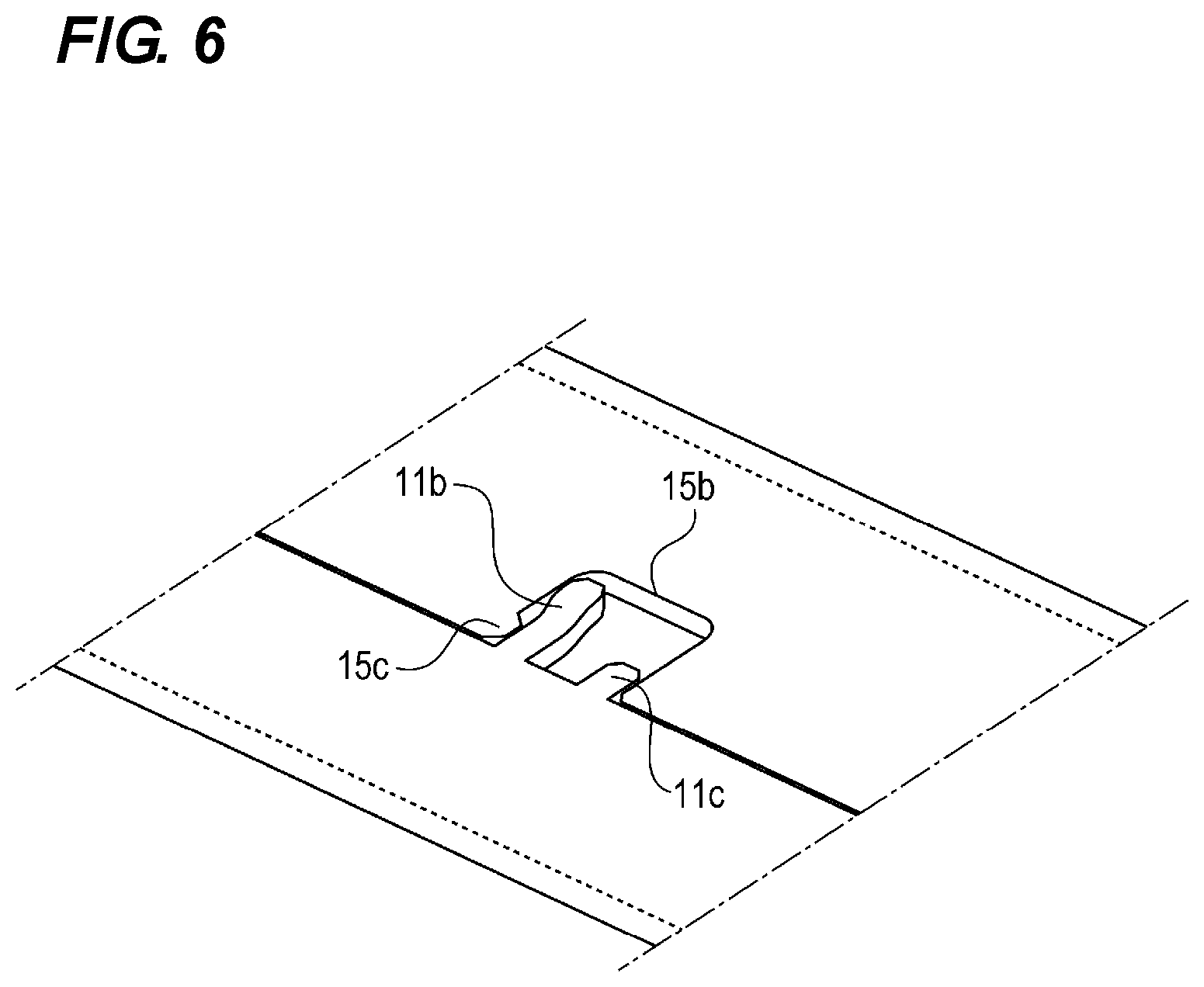
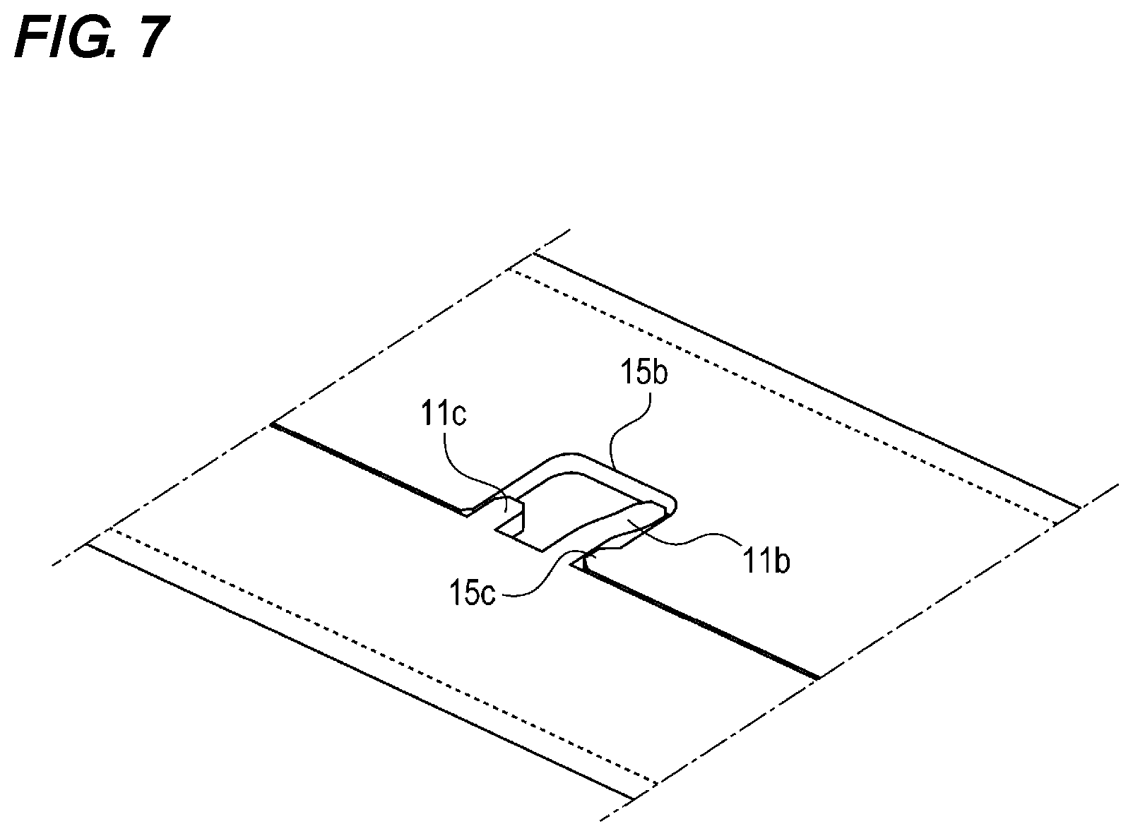
[0021] FIG. 7 is a partially enlarged view of the protruding portion and the recessed portion.
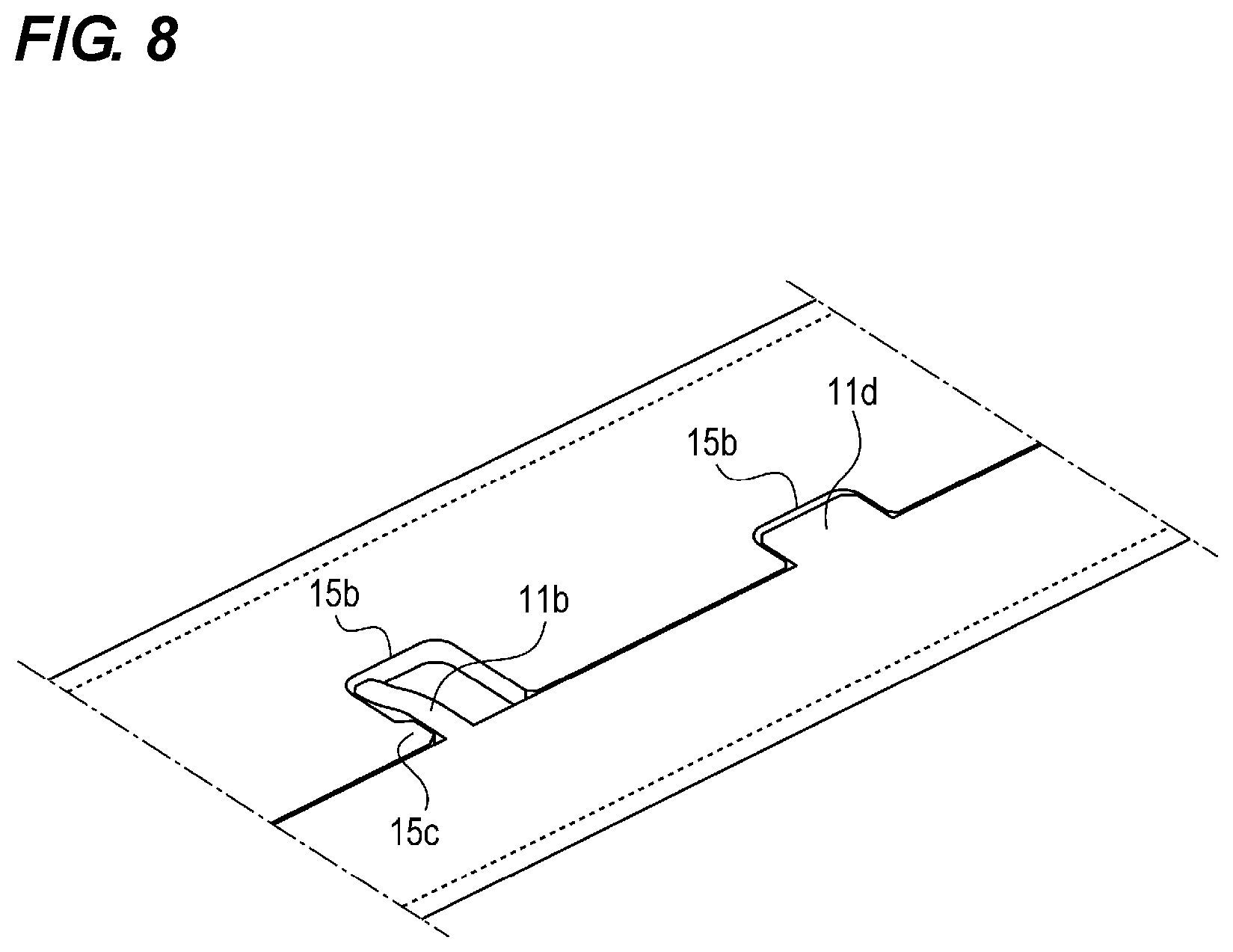
[0022] FIG. 8 is a partially enlarged view of a movement restricting protrusion and a movement restricting recessed portion.
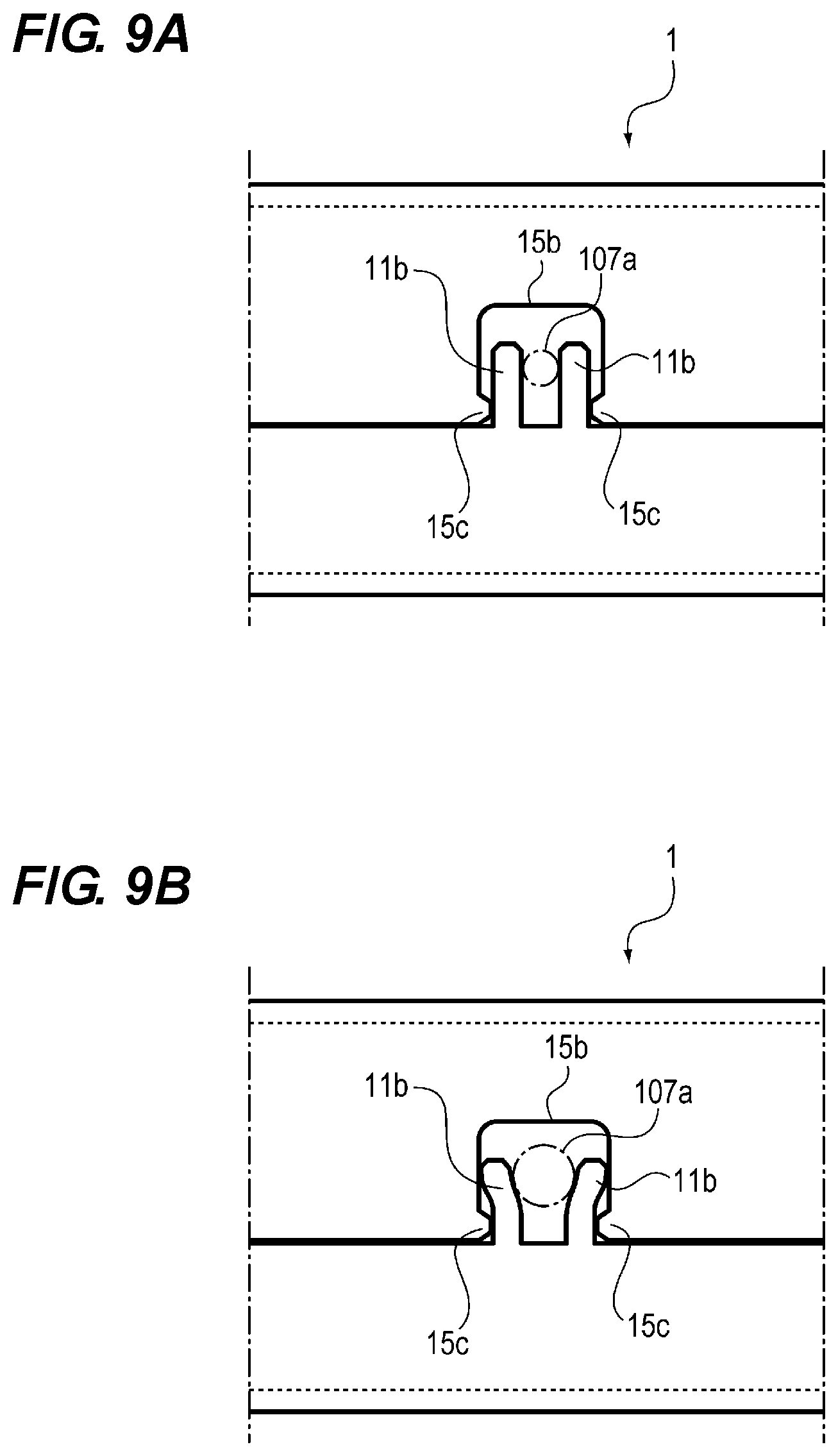
[0023] FIGS. 9A and 9B are partially enlarged views of the protruding portion and the recessed portion.
[0024] FIG. 10 is a partially enlarged view of the protruding portion and the recessed portion.
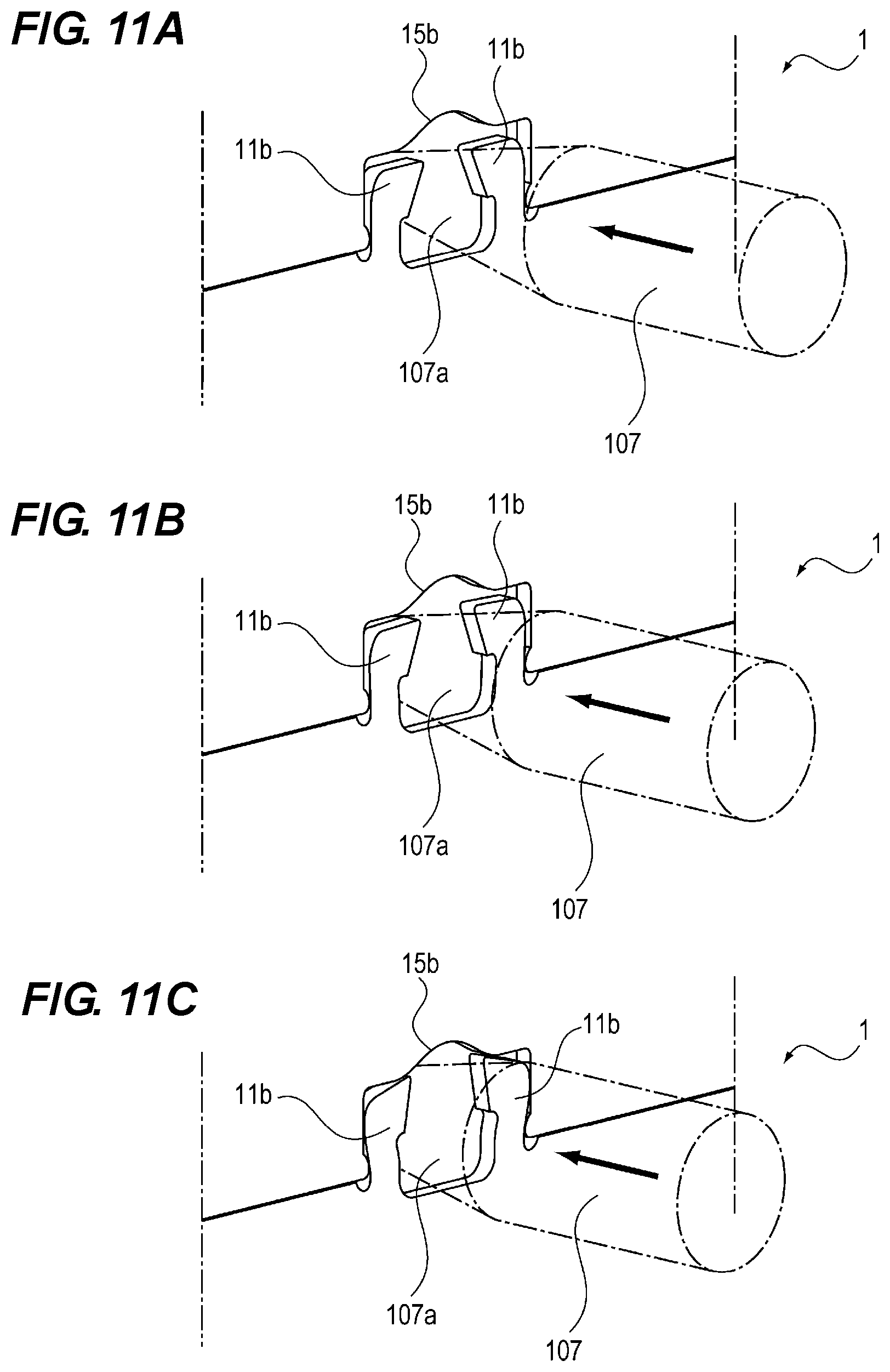
[0025] FIGS. 11A to 11C are schematic perspective views for explaining a bending process for bending the protruding portion.
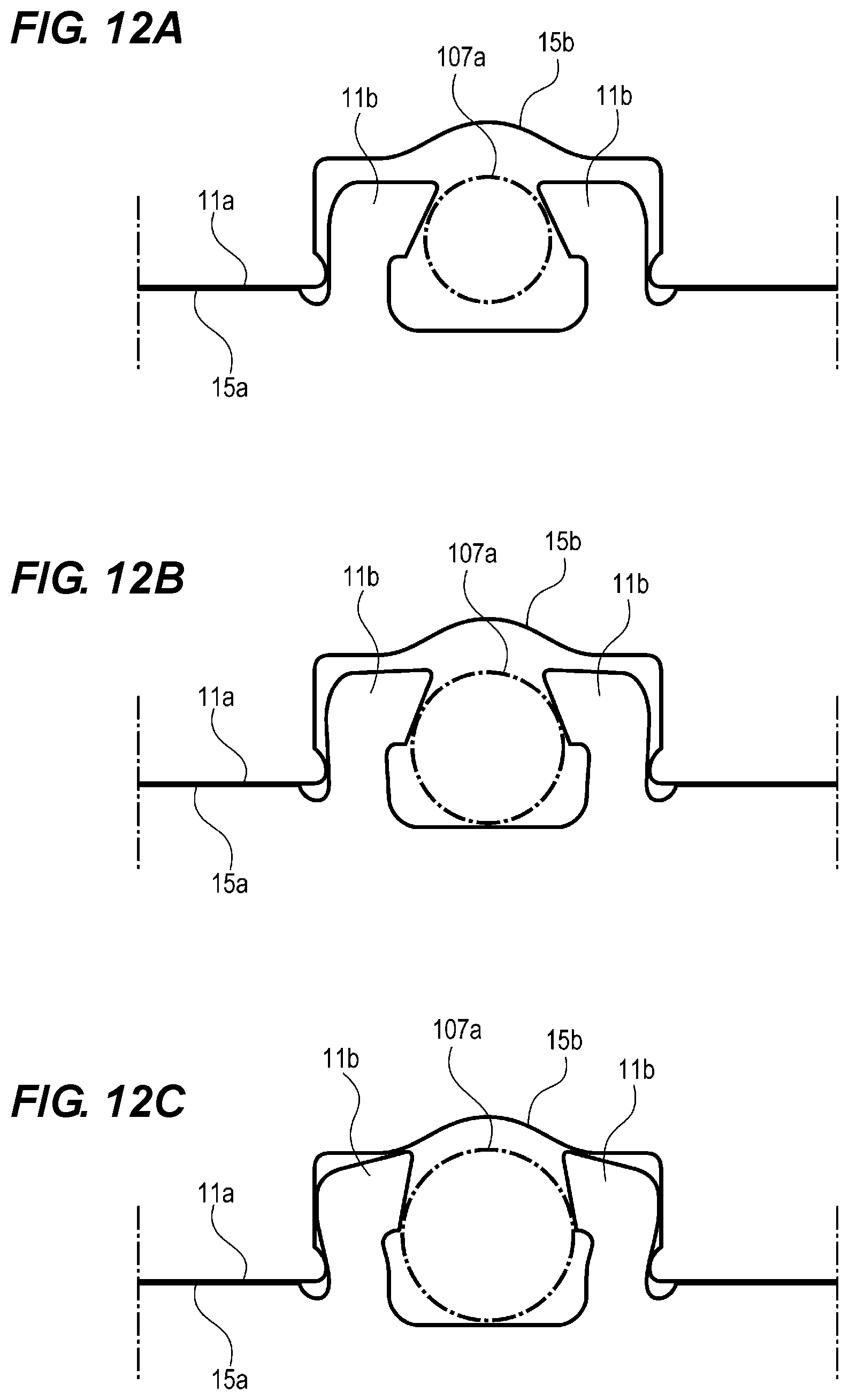
[0026] FIGS. 12A to 12C are schematic plan views for explaining the bending process for bending the protruding portion.
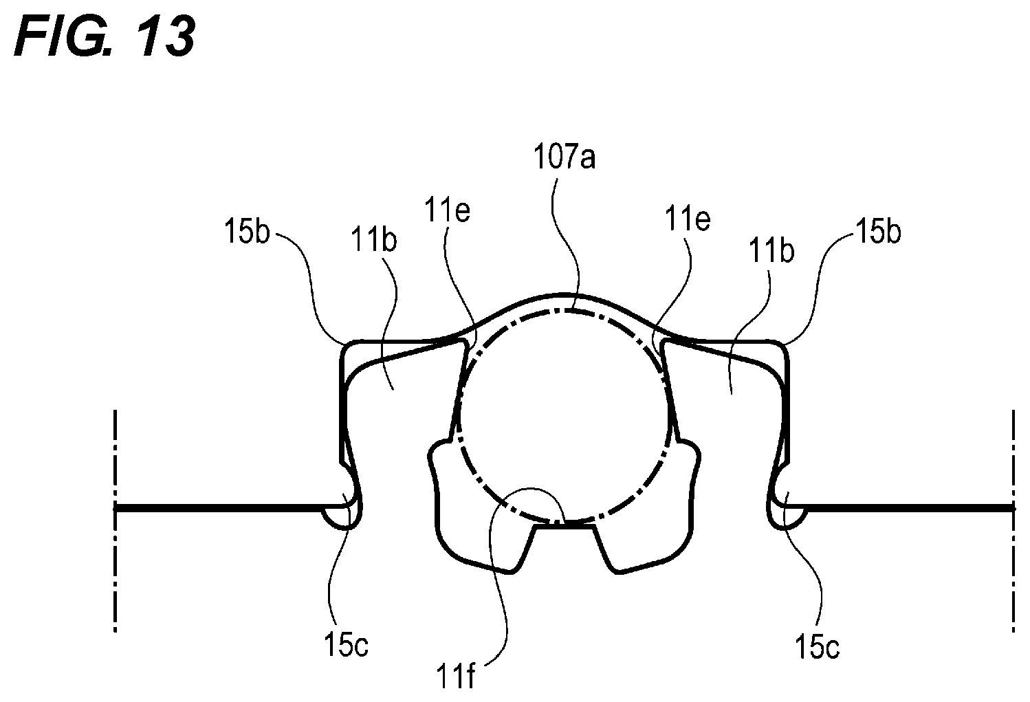
[0027] FIG. 13 is a partially enlarged view of the protruding portion and the recessed portion.
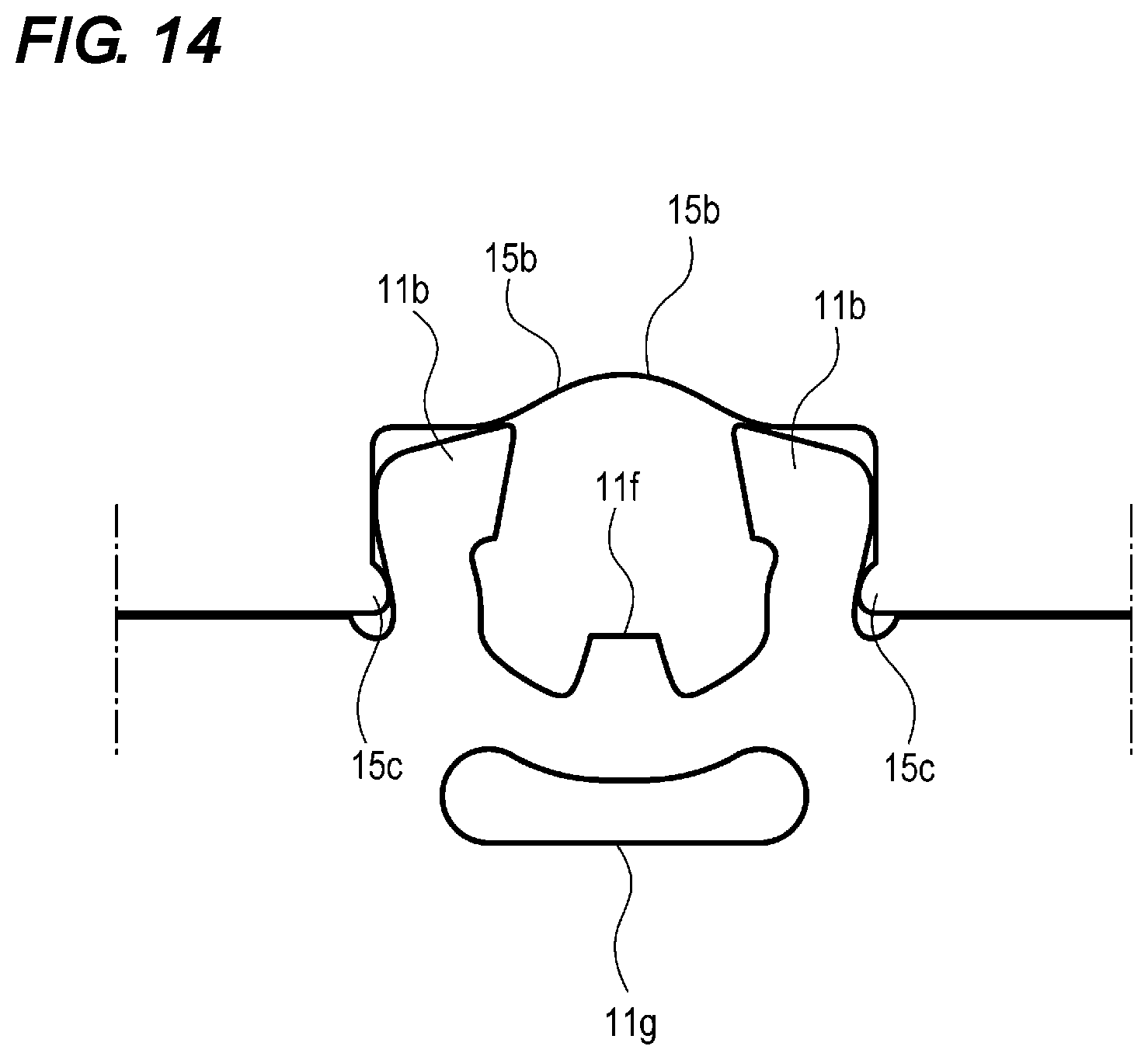
[0028] FIG. 14 is a partially enlarged view of the protruding portion and the recessed portion.
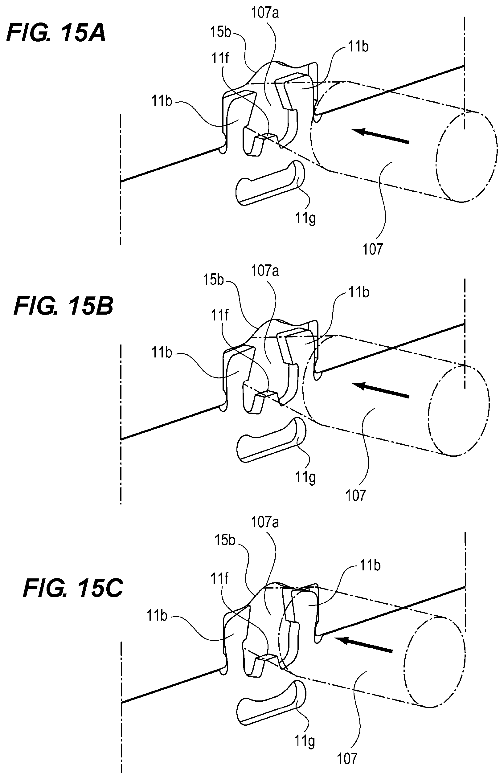
[0029] FIGS. 15A, to 15C are schematic perspective views for explaining a bending process for bending the protruding portion.
[0030] FIGS. 16A to 16C are schematic plan views for explaining the bending process for bending the protruding portion.
[0031] FIGS. 17A and 17B are perspective views showing a tubular body having another cross-sectional shape.
DESCRIPTION OF THE EMBODIMENTS
First Embodiment
[0032] Hereinafter, the configuration of a metal plate according to the first embodiment of the present invention will be described with reference to the drawings. Note that the dimensions, materials, shapes, relative arrangements, and the like of the described components are not intended to limit the scope of the present invention only to those unless otherwise specified.
[0033] FIG. 1 is a perspective view of the tubular body 1, and FIG. 2 is a developed perspective view of the tubular body 1. As shown in FIGS. 1 and 2, the tubular body 1 has a prism shape and is formed by bending the sheet metal 1a by 90 degrees along four parallel lines L1 to L4, respectively, and by joining the end portion 11a (one end portion) with the end portion 15a (the other end portion). The end portion 11a forms one side of the metal plate 1a and is substantially parallel to the lines L1 to L4. The end portion 15a forms another side of the sheet metal 1a and is substantially parallel to the lines L1 to L4. The end portion 11a and the end portion 15a of the metal plate 1a before the bending process are the sides placed in opposite directions with respect to the lines L1 to L4. Here, in this embodiment, the metal plate 1a is an electro-galvanized steel plate formed by the punching process from a metal plate having a thickness of 1 mm as a raw material. Moreover, the outer dimension of the tubular body 1 is 18 mm.times.25 mm, and the full length is 500 mm. The material of the metal plate 1a is not limited to this, and may be a stainless or aluminum material. Moreover, although the thickness of the sheet metal 1a is exemplified as 1 mm, the thickness of the metal plate 1a is desirably 0.4 mm or more and 2 mm or less.
[0034] Next, the joint between the end portion 11a (end surface) and the end portion 15a (end surface) of the metal plate 1a of the tubular body 1 will be described. As shown in FIG. 2, each of the end portion 11a and the end portion 15a forms a side of the metal plate 1a. The X-axis direction in FIG. 2 is defined as a first direction in which the first side formed by the end portion 11a of the metal plate la and the second side formed by the end portion 15a extend. The first side and the second side are parallel to each other. Further, the Y-axis direction perpendicular to the X-axis direction is defined as a second direction in which the third side and the fourth side of the metal plate 1a extend. The third side and the fourth side are respectively perpendicular to the first side and the second side. A direction along the planar defined by the X-axis direction and the Y-axis direction is a planar direction of the metal plate 1a before pressing. Furthermore, the Z-axis direction is defined as a third direction that is the thickness direction of the metal plate 1a. The Z-axis direction is a direction perpendicular to the X-axis and the Y-axis. At the end 15a of the metal plate 1a, the recess 15b is formed by cutting out the metal plate 1a in the planar direction. Further, at a position corresponding to the recessed portion 15b at the end portion 11a of the metal plate 1a, a protruding portion 11b is formed which protrudes in the planar direction of the metal plate 1a. The dashed-dotted line shown in FIG. 2 is a bending line along which the metal plate 1a is bent in the press work mentioned later. The protruding portion 11b is disposed within the range of the width in the X-axis direction of the recessed portion 15b. Therefore, as described later, when the metal plate la is bent along the dashed-dotted line, the protruding portion 11b fits into the recessed portion 15b formed by an end surface (surface along the thickness direction of the metal plate 1a). The length (the length in the Y-axis direction) from the proximal end portion to the distal end portion of the protruding portion 11b is equal to or less than the depth in the Y-axis direction of the recessed portion 15b at a position corresponding to the protruding portion 11b. In this embodiment, since the rectangular metal plate 1a is used, the third side and the fourth side are parallel to the first side and the second side. However, it is not necessary for the third side and the fourth side to be parallel to the first side and the second side. Further, it is not necessary for the third side to be parallel to the fourth side. Furthermore, the end portion of the metal plate 1a connecting the first side and the second side may be formed by a plurality of sides instead of the third side and the fourth side.
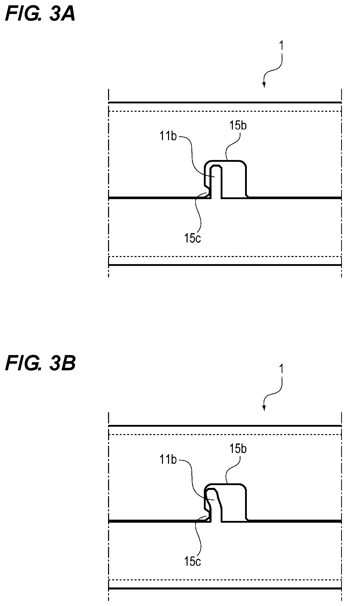
[0035] FIGS. 3A and 3B are partially enlarged views of the protruding portion 11b and the recessed portion 15b. FIG. 3A shows a state where the protruding portion 11b is not yet deformed (before processing). FIG. 3B shows a state where the protruding portion 11b has already been deformed (after processing). As shown in FIGS. 3A and 3B, the protruding portion 15c is provided at the recessed portion 15b. As shown in FIG. 3A, the protruding portion 15c is provided in the recessed portion 15b such that the protruding portion 15c is so positioned that the protruding portion 15c is located closer to the proximal end portion of the protruding portion 11b than the distal end portion of the protruding portion 11b when the end portion 11a and the end portion 15a are joined. The protruding portion 15c is provided in the recessed portion 15b such that the protruding portion 15c protrudes toward the protruding portion 11b when the end portion 11a and the end portion 15a are joined. That is, the protruding portion 15c is a portion protruding in the longitudinal direction of the tubular body 1. In joining the end portion 11a and the end portion 15a of the metal plate 1a, the protruding portion 11b is bent in the left direction in FIGS. 3A and 3B after being fitted in the recessed portion 15b. As a result, the protruding portion 11b is plastically deformed and hooks the protruding portion 15c so that the protruding portion 11b engages with the protruding portion 15c (engaging portion) at a position where the side surface of the protruding portion 11b is opposed to the protruding portion 15c which is formed to protrude in the longitudinal direction of the tubular body 1.
[0036] As described above, by engaging the protruding portion 11b with the protruding portion 15c such that the protruding portion 15c is hooked by the protruding portion 11b at the joint of the end portions 11a and 15a of the metal plate 1a, the adhesion between the end portions 11a and 15a is maintained, resisting the force in a direction in which the end portions 11a and 15a separate from each other, namely, the force for opening the metal plate 1a due to the spring back.
[0037] Moreover, when the length from the proximal end portion to the distal end portion of the protruding portion 11b is set to be less than the depth of the recessed portion 15b located at a position corresponding to the protruding portion 11b, the protruding portion 11b s prevented from buckling when the side portion 11a and the side portion 15a are joined. In addition, the depth here is defined as the distance between the end portion 15a and the surface of the recessed portion 15b opposed to the distal end portion of the protruding portion 11b. Therefore, the accuracy of the engagement of the protruding portion 11b with the protruding portion 15c is maintained.
[0038] Therefore, with the configuration described above, the end portion 11a and the end portion 15a stably adhere to each other at the joint between the end portion 11a and the end portion 15a in the tubular body 1 formed from the single sheet of the metal plate 1a.
[0039] Next, a method of manufacturing the tubular body 1 will be described.
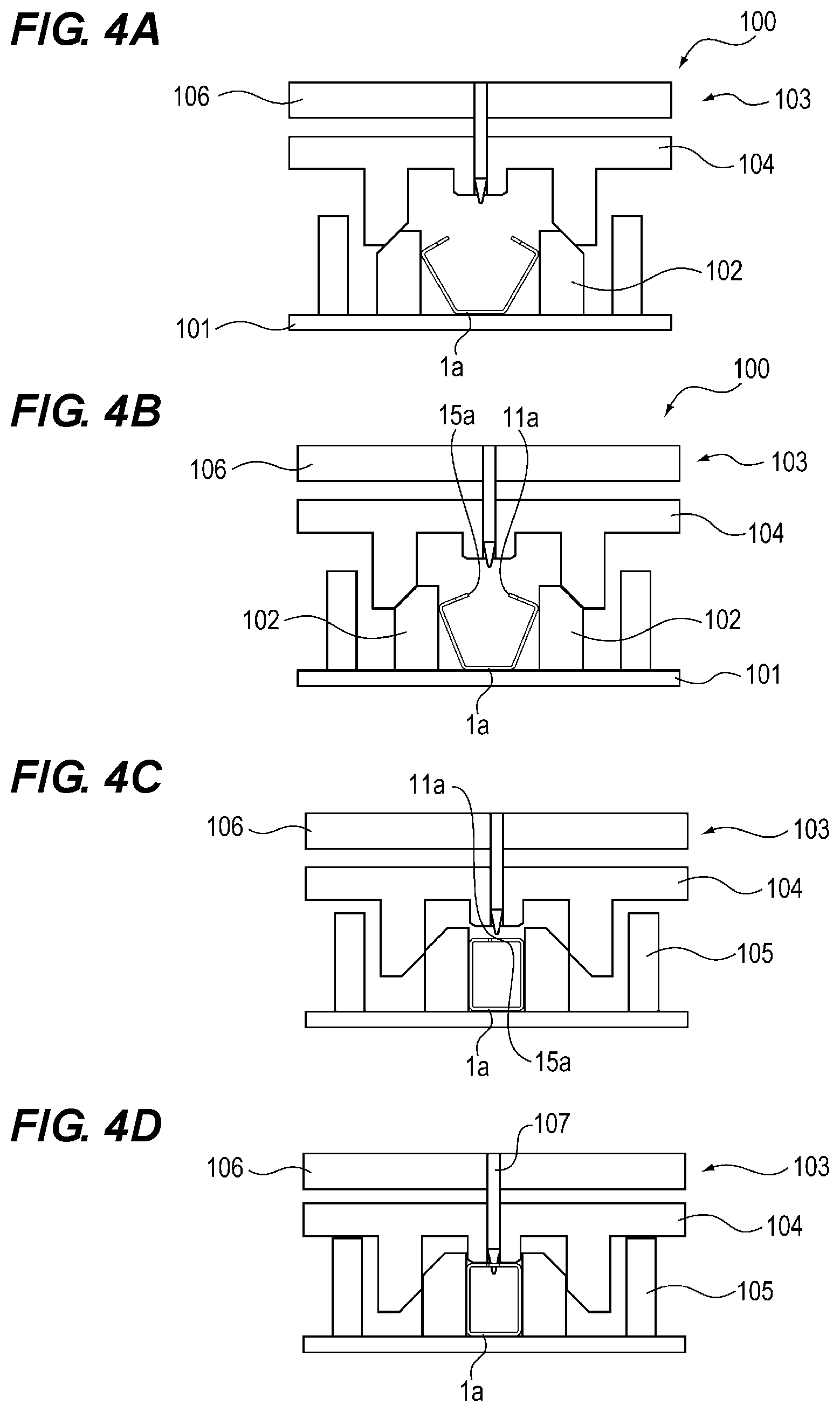
[0040] FIGS. 4A, 4B, 4C and 4D are schematic diagrams for explaining a bending process when the tubular body 1 is manufactured. When manufacturing the tubular body 1, as shown in FIG. 4A, the metal plate la is firstly bent along the lines L 1 to L 4 (see FIGS. 2A and 2B) by the press machine 100, and then the metal plate 1a is set so as to be nipped between the slide blocks 102 on the base plate 101 of the press machine 100.
[0041] Next, as shown in FIG. 4B, by lowering the upper die 103, the slide blocks 102 approach each other on the base plate 101, and accordingly the end portions 11a and 15a of the metal plate 1a approach each other. Thereafter, when the upper die 103 is further lowered, as shown in FIG. 4C, the end portion 11a and the end portion 15a of the metal plate 1a are joined.
[0042] Next, as shown in FIG. 4D, when the upper die 103 is further lowered, the slide plate 104 abuts against the stopper block 105 and the lowering of the slide plate 104 is restricted. When the upper die 103 is lowered in this state, only the punch plate 106 with the caulking punch 107 (pressing member) descends, and the caulking punch 107 enters the recessed portion 15b of the metal plate 1a. The caulking punch 107 includes the tapered portion 107a at the distal end portion. The tapered portion 107a is inclined with a taper angle of 20.degree. to the entering direction.
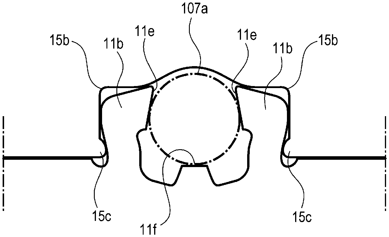
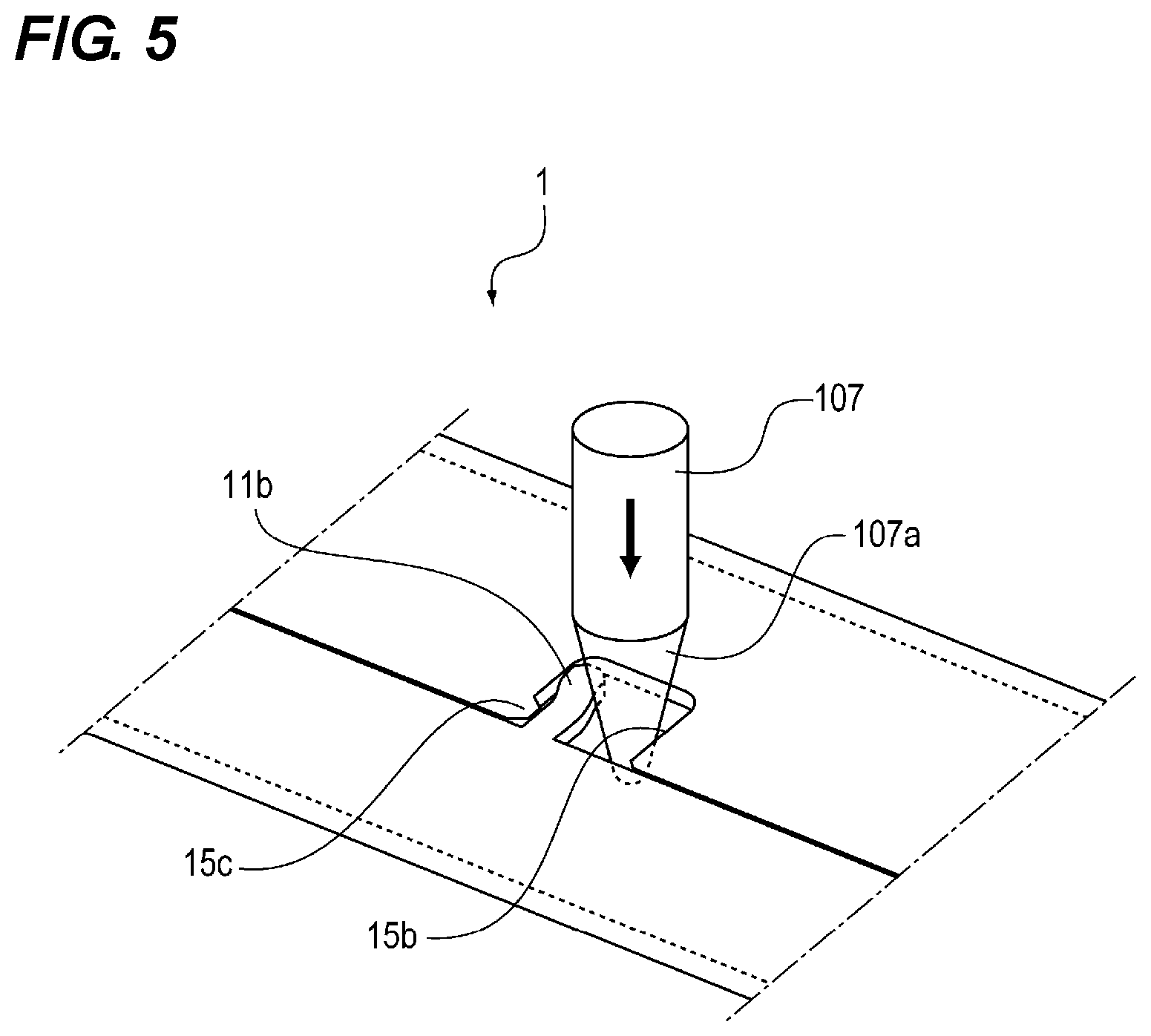
[0043] FIG. 5 is a perspective view showing a state where the caulking punch 107 enters the recessed portion 15b. As shown in FIG. 5, in the state where the protruding portion 11b is placed in the recessed portion 15b of the metal plate 1a, the caulking punch 107 enters the space surrounded by the recessed portion 15b, the protruding portion 11b and the end portion 15a which are located at an opposite side of the protruding portion 15c with respect to the protruding portion 11b. Accordingly, the protruding portion 11b is pressed and bent in the longitudinal direction of the tubular body 1 by the taper portion 107a of the caulking punch 107. As a result, the protruding portion 11b is caulked such that the protruding portion 11b is engaged with the protruding portion 15c so that the protruding portion 15c is hooked by the protruding portion 11b, thereby forming the tubular body 1 with the end portion 11a and the end portion 15a being joined with high adhesion.
[0044] In the present embodiment, the configuration has been described in which four recessed portions 15b and four protruding portions 11b are provided in the longitudinal direction of the tubular body 1. However, the present invention is not limited to this configuration, and the number of the recessed portions 15b and the protruding portions 11b can be appropriately changed.
[0045] Moreover, in the present embodiment, the configuration has been described in which the bending directions of the four protruding portions 11b are the same. However, the present invention is not limited to this configuration, and a configuration in which the bending direction of the protruding portions 11b and the arrangement of the protruding portion 15c are reversed in the longitudinal direction of the tubular body 1 or a configuration in which both configurations are mixed may be employed.
Second Embodiment
[0046] Next, the configurations of the second embodiment of the tubular body according to the present invention will be described with reference to the drawings. The portions whose descriptions are duplicate with those of the first embodiment are omitted by attaching the same reference numerals as those of the first embodiment.
[0047] FIG. 6 is a partially enlarged view of the protruding portion 11b and the recessed portion 15b of the tubular body 1 according to the present embodiment. As shown in FIG. 6, the end portion 11a of the metal plate 1a is provided with a movement restricting protrusion 11c (restricting portion) which engages with the recessed portion 15b of the end portion 15a on the opposite side of the protruding portion 11b in the longitudinal direction of the tubular body 1. The movement restricting protrusion 11c engages with the recessed portion 15b without being bent, unlike the protruding portion 11b.
[0048] By providing the movement restricting projection 11c that engages with the protruding portion 15b separately from the convex portion 11b, it is possible to suppress a relative movement of the end portion 11a and the end portion 15a in the longitudinal direction of the tubular body 1 when the protruding portion 11b is bent. Accordingly, the engagement between the protruding portion 11b and the protruding portion 15c can be further stabilized, thereby securing the adhesion of the end portion 11a and the end portion 15a at the joint between them.
[0049] The positional relationship between the movement restricting protrusion 11c and the protruding portion 11b is not limited to the configuration of the above configuration of the present embodiment. That is, as shown in FIG. 7, for example, the positional relationship between the protruding portion 11b and the movement restricting protrusion 11c may be reversed in the longitudinal direction of the tubular body 1. Moreover, the configuration with both different positional relationships can be adopted. As a result, the movement restricting protrusions 11c include those of which the directions of restricting the movements are opposite to each other. Therefore, it is possible to suppress more effectively the shifting of the relative positions of the end 11a and the end 15a in the longitudinal direction of the tubular body 1.
[0050] Further, the arrangement of the movement restricting protrusions 11c is not limited to the above configurations of the present embodiment. That is, as shown in FIG. 8, for example, the end portion 15a may be provided with the movement restricting recessed portion 15d that engages with the movement restricting protrusion 11c separately from the recessed portion 15b which the protruding portion 11b enters. In this configuration, the same effect may be obtained. Alternatively, the movement restricting protrusion 11c may be provided at the end portion 15a, and the movement restricting recessed portion 15d may be provided at the end portion 11a.
Third Embodiment
[0051] Next, the configurations of the third embodiment of the tubular body according to the present invention will be described with reference to the drawings. The portions whose descriptions are duplicate with those of the first and second embodiments are omitted by attaching the same reference numerals as those of these embodiments.
[0052] FIGS. 9A and 9B are partially enlarged views of the protruding portion 11b and the recessed portion 15b of the tubular body 1 according to the present embodiment. FIG. 9A shows a state where the protruding portion 11b is not yet deformed, and FIG. 9B shows a state where the protruding portion 11b has been deformed.
[0053] As shown in FIG. 9, in the present embodiment, a pair (a plurality) of protruding portions 11b formed in the end portion 11a enter the single recessed portion 15b formed at the end portion 15a of the metal plate 1a. Then, with the pair of protruding portions 11b being in the recessed portion 15b, the caulking punch 107 enters from above the space between the pair of protruding portions 11b positioned in the recessed portion 15b. Accordingly, the pair of protruding portions 11b are respectively bent by the tapered portion 107a of the caulking punch 107. The pair of protruding portions 11b are engaged with the pair of protrusion portions 15c (a plurality of engaging portion) such that the pair of protruding portions 11b are hooked on the pair of protrusion portions 15c formed to protrude in the longitudinal direction of the tubular body 1 at the portions opposed to the side surfaces of the protruding portions 11b positioned in the recessed portion 15b. The bending directions of the pair of protruding portions 11b are opposite to each other in the longitudinal direction of the tubular body 1.
[0054] As described above, the pair of protruding portions 11b are respectively engaged with the pair of protruding portions 15c in the recessed portion 15b so that the end portions of the metal plate 1b can stably adhere to each other at the joint between them.
Fourth Embodiment
[0055] Next, the configurations of the fourth embodiment of the tubular body according to the present invention will be described with reference to the drawings. The portions whose descriptions are duplicate with those of the first, second and third embodiments are omitted by attaching the same reference numerals as those of these embodiments.
[0056] FIG. 10 is a partially enlarged view of the protruding portion 11b and the recessed portion 15b of the tubular body 1 according to the present embodiment. As shown in FIG. 10, in this embodiment, the width of the protruding portion 11b formed on the end portion 11a of the metal plate 1a increases from the proximal end portion to the distal end portion. Further, the edge portions 11e of the pair of protruding portions 11b against which the taper portion 107a of the caulking punch 107 abuts at the time of bending are inclined an angle a with respect to the line Y connecting the centers of the distances between both protruding portions 11b such that the gap between both edge portions becomes narrower from the proximal end to the distal end.
[0057] FIGS. 11A, 11B and 11C are schematic perspective views which illustrate the step of bending the protruding portion 11b in the bending process by the above-described caulking punch 107. FIGS. 12A, 12B and 12C are schematic plan views respectively corresponding to FIGS. 11A, 11B and 11C. Here, in FIGS. 11A to 11C and 12A to 12C, the manner in which the caulking punch 107 descends is shown in the order of FIGS. 11A to 11C and FIGS. 12A to 12C. A dashed-dot line shown in FIGS. 12 A to 12C indicates a cross-section of the caulking punch 107 on the plane of the metal plate.
[0058] As shown in FIGS. 11A to 11C and 12A to 12C, when the protruding portion 11b is bent and caulked, the caulking punch 107 gradually enters the recessed portion 15b from above, and the taper portion 107a of the caulking punch 107 presses the edge portion 11e of the protruding portion 11b to bend the protruding portion 11b. As a result, the protruding portion 11b engages the protruding portion 15c such that the protruding portion 11b is hooked on the protruding portion 15c that protrudes in the longitudinal direction of the tubular body 1 the portion opposed to the side surface of the protruding portion 11b positioned in the recessed portion 15b.
[0059] As described above, the edge portions 11e are inclined at an angle a with respect to the line Y (see FIG. 10). For this reason, in the process of bending the protruding portion 11b by the caulking punch 107, a force may be generated in a direction from the end portion 11a toward the end portion 15a, thereby improving adhesion between the end portion 11a and the end portion 15a.
[0060] In addition, it is preferable that the width X (see FIGS. 11A, 11B and 11C) of the proximal end part of the protruding portion 11b is 0.5 to 1.5 times the thickness of the metal plate 1a. When the width X is less than 0.5 times the thickness, the caulking strength is weak and the joint between the end portion 11a and the end portion 15a is easily opened against the force of the spring-back of the bending process. When the width X is larger than 1.5 times, there is a possibility that the protruding portion 11b is bent toward the inside of the tubular body 1 when the protruding portion 11b is pressed by the caulking punch 107 in the bending process described so that the caulking strength becomes weak.
[0061] In the present embodiment, an electro-galvanized steel plate having a thickness of 1 mm is used as the metal plate 1a, and the metal plate 1a is processed such that the width X is 1.3 mm. As a result, a sufficient caulking strength was obtained although the distal end of the protruding portion 11b is bent toward the inside of the tubular body 1 about 0.2 mm in the bending process by the above-described caulking punch 107. In addition, when the distal end of the protruding portion 11b enters the inside of the tubular body 1 in this way, the protruding portion does not outwardly protrude from the outer surface of the tubular body 1. Thus, when the tubular bodies 1 are combined with each other or the tubular body 1 is combined with other members, the tubular body 1 does not interfere with other tubular bodies 1 or other members.
First Modification Example
[0062] Next, as a first modification example of the present embodiment, the configuration will be described in which the abutting portion 11f is provided at the end portion 11a of the metal plate 1a.
[0063] FIG. 13 is a partially enlarged view of the protruding portion 11b and the recessed portion 15b according to the first modification example. As shown in FIG. 13, in the first modification example, the abutting portion 11f is provided which abuts against the taper portion 107a of the caulking punch 107 together with the pair of protruding portions 11b when the caulking punch 107 enters the recessed portion 15b in the bending process by the caulking punch 107.
[0064] Thus, when the protruding portion 11b is bent by the caulking punch 107, the caulking punch 107 can be supported at three points, and a load can be stably applied to the protruding portion 11b. Therefore, the accuracy of the engagement of the protruding portion 11b with the protruding portion 15c is improved.
Second Modification Example
[0065] Next, as a second modification example of the present embodiment, the configuration will be described in which the hole 11g is provided in the vicinity of the abutting portion 11f.
[0066] FIG. 14 is a partially enlarged view of the protruding portion 11b and the recessed portion 15b according to the second modification example. As shown in FIG. 14, in the second modification example, the hole 11g is provided in the vicinity of the abutting portion 11f in addition to the configuration of the first modification example. Next, the bending process of the protruding portion 11b in this configuration will be described.
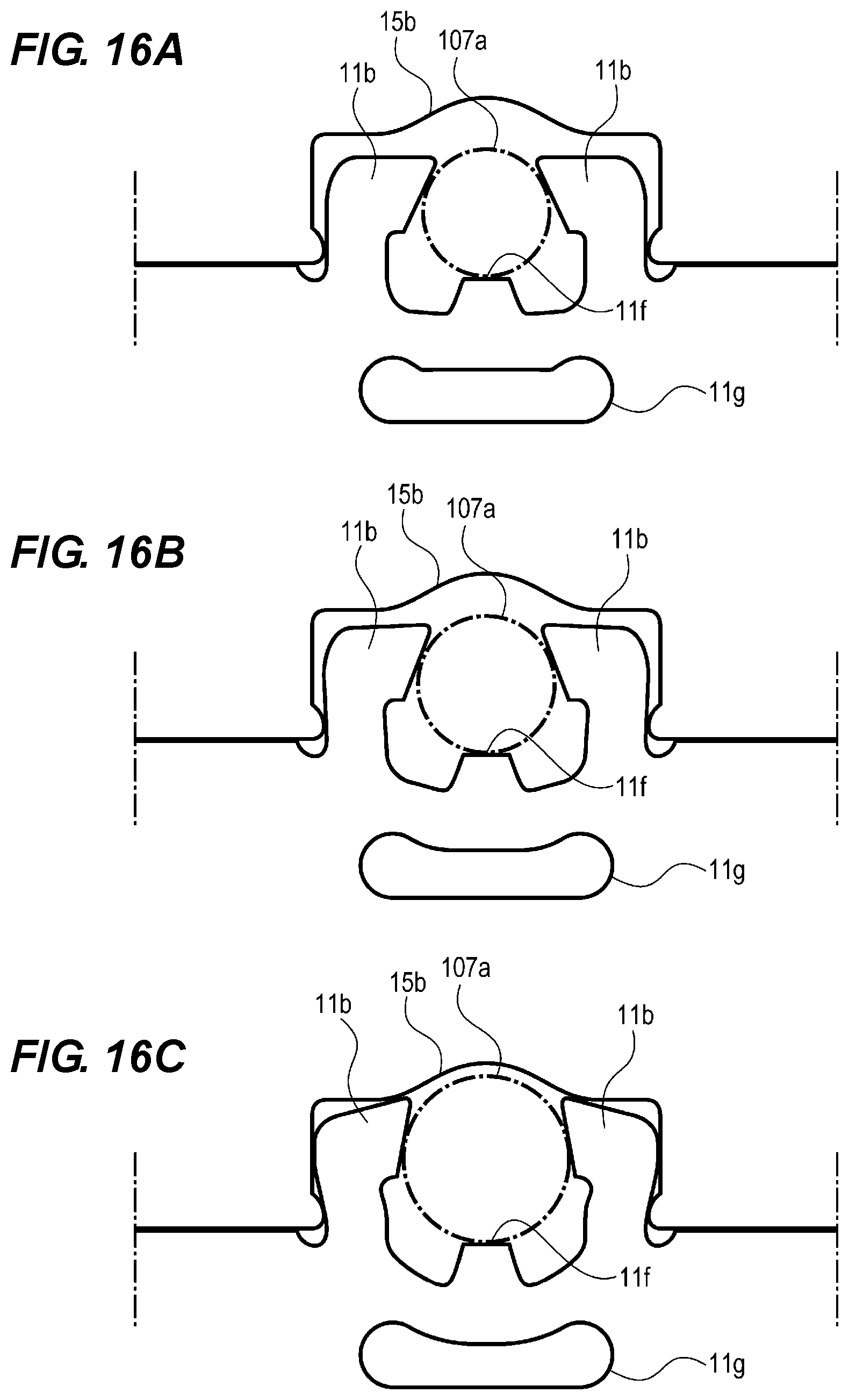
[0067] FIGS. 15A, 15B and 15C are schematic perspective views which illustrate the step of bending the protruding portion 11b in the bending process by the above described caulking punch 107. FIGS. 16A, 16B and 16C are schematic plan views respectively corresponding to FIGS. 15A, 15B and 15C. Here, in FIGS. 15A to 15C and 16A to 16C, the manner in which the caulking punch 107 descends is shown in the order of FIGS. 15A to 15C and FIGS. 16A to 16C. A dashed-dot line shown in FIGS. 16 A to 16C indicates a cross-section of the caulking punch 107 on the plane of the metal plate.
[0068] As shown in FIGS. 15A to 15C and 16A to 16C, when the protruding portion 11b is bent, the caulking punch 107 gradually enters the recessed portion 15b from above, and the taper portion 107a of the caulking punch 107 presses the protruding portion 11b to bend the protruding portion 11b. As a result, the protruding portion 11b engages the protruding portion 15c such that the protruding portion 11b is hooked on the protruding portion 15c.
[0069] When the protruding portion 11 b is bent by the caulking punch 107, the hole 11g contracts due to the pressure from the caulking punch 107 received by the abutting portion 11f that abuts against the caulking punch 107 together with the protruding portion 11b. As a result, the abutting portion 11f moves in a direction in which the abutting portion 11f retracts from the caulking punch 107. Thus, with the configuration in which the abutting portion 11f moves along with the protruding portion 11b, the movement of the axial position of the caulking punch 107 is suppressed when the protruding portion 11b is bent by the caulking punch 107. Therefore, the shape of the configuration of the tubular body 1 and the operation of producing it are stabilized, thereby improving takt time.
[0070] In the first to fourth embodiments, the taper angle of the caulking punch 107 is set to 20.degree., namely, an inclined angle of 10.degree.. However, the present invention is not limited to this, and other taper angles may be used. However, it is preferable to satisfy 10.degree..ltoreq..theta..ltoreq.30.degree. where .theta. represents the taper angle.
[0071] The reason why this range is selected is as follows. When the taper angle is less than 10.degree., there is a possibility that the lifting and lowering stroke of the caulking punch 107 becomes large and that when the caulking punch 107 is lifted, the tubular body 1 may be lifted with the caulking punch 107. Further, when the taper angle is greater than 30.degree., the protruding portion 11b may easily be bent toward the inside of the tubular body 1.
[0072] In the first to fourth embodiments, the method of processing the metal plate 1a using the conical caulking punch 107 is exemplified. However, the present invention is not limited to this, and may have another configuration as long as the configuration has a tapered portion. For example, the caulking punch 107 having a quadrangular pyramid shape may be used.
[0073] In the first to fourth embodiments, the present invention has been described by exemplifying a tubular body with a quadrangular prism shape. However, the present invention is not limited to this, can be applied to tubular bodies regardless of the cross-sectional shape of the tubular body 1, such as the tubular body with a triangular prism shape shown in FIG. 17A and the tubular body with a cylindrical shape in FIG. 17B.
[0074] Further, the tubular body 1 according to the present invention can be used for various applications including a frame of an image forming apparatus such as a multi-functional machine or a printer.
[0075] The present invention is not limited to the above embodiments, and various modifications and variations can be made without departing from the spirit and scope of the present invention. Therefore, the following claims are attached so as to make public the scope of the present invention.
[0076] According to the present invention, in a tubular body formed by combining one end of a single metal plate with another end of the single metal plate, both ends can stably adhere to each other.
[0077] While the present invention has been described with reference to exemplary embodiments, it is to be understood that the invention is not limited to the disclosed exemplary embodiments. The scope of the following claims is to be accorded the broadest interpretation so as to encompass all modifications, equivalent structures and functions.
INDUSTRIAL APPLICABILITY
[0078] The present invention relates to a metal plate and a method for manufacturing a tubular body, and has industrial applicability.
* * * * *
D00000
D00001
D00002
D00003
D00004
D00005
D00006
D00007
D00008
D00009
D00010
D00011
D00012
D00013
D00014
D00015
D00016
D00017

XML
uspto.report is an independent third-party trademark research tool that is not affiliated, endorsed, or sponsored by the United States Patent and Trademark Office (USPTO) or any other governmental organization. The information provided by uspto.report is based on publicly available data at the time of writing and is intended for informational purposes only.
While we strive to provide accurate and up-to-date information, we do not guarantee the accuracy, completeness, reliability, or suitability of the information displayed on this site. The use of this site is at your own risk. Any reliance you place on such information is therefore strictly at your own risk.
All official trademark data, including owner information, should be verified by visiting the official USPTO website at www.uspto.gov. This site is not intended to replace professional legal advice and should not be used as a substitute for consulting with a legal professional who is knowledgeable about trademark law.