Falling Object Catching Toy
NOBATA; Fujio
U.S. patent application number 16/566172 was filed with the patent office on 2020-03-26 for falling object catching toy. The applicant listed for this patent is SEGA TOYS CO., LTD.. Invention is credited to Fujio NOBATA.
| Application Number | 20200094130 16/566172 |
| Document ID | / |
| Family ID | 69883040 |
| Filed Date | 2020-03-26 |


| United States Patent Application | 20200094130 |
| Kind Code | A1 |
| NOBATA; Fujio | March 26, 2020 |
FALLING OBJECT CATCHING TOY
Abstract
A falling object catching toy according to the present invention includes a case body, a pair of holding members that are pivotally supported by the case body and are formed in a manner capable of holding a falling object by being biased in an opening direction, a rotation knob that is rotatably provided for the case body, having a protruding part positioned within the case body, and a piece body having a regulating part that is movably provided while being biased to one side within the case body to regulate the bias of the holding members in the opening direction by engagement with the holding members, and a releasing protrusion that abuts on the protruding part to cause movement against biasing force to release the regulation of the holding members by the regulating part.
| Inventors: | NOBATA; Fujio; (Tokyo, JP) | ||||||||||
| Applicant: |
|
||||||||||
|---|---|---|---|---|---|---|---|---|---|---|---|
| Family ID: | 69883040 | ||||||||||
| Appl. No.: | 16/566172 | ||||||||||
| Filed: | September 10, 2019 |
| Current U.S. Class: | 1/1 |
| Current CPC Class: | A63B 71/06 20130101; A63F 9/30 20130101; A63F 9/0096 20130101; A63B 2225/093 20130101; A63B 2071/0675 20130101; A63F 2250/1042 20130101; A63B 2071/0694 20130101; A63B 69/0053 20130101; A63F 7/02 20130101; A61B 5/162 20130101 |
| International Class: | A63F 9/00 20060101 A63F009/00; A63F 9/30 20060101 A63F009/30 |
Foreign Application Data
| Date | Code | Application Number |
|---|---|---|
| Sep 25, 2018 | JP | 2018-178939 |
Claims
1. A falling object catching toy, comprising: a case body; a pair of holding members that are pivotally supported by the case body and are formed in a manner capable of holding a falling object with tip parts by being biased in an opening direction; a rotation knob that is rotatably provided for the case body, having a protruding part positioned within the case body; and a piece body comprising a regulating part that is movably provided while being biased to one side within the case body to regulate the bias of the holding members in the opening direction by engagement with the holding members, and a releasing protrusion that abuts on the protruding part to cause movement against biasing force to release the regulation of the holding members by the regulating part.
2. The falling object catching toy according to claim 1, wherein the case body is provided with a spiral-spring driving part, and the rotation knob is connected to a driving shaft of the spiral-spring driving part.
3. The falling object catching toy according to claim 2, wherein the case body is provided with a spiral-spring driving operation part for operating wind-up and release of a spiral spring of the spiral-spring driving part.
4. The falling object catching toy according to claim 1, wherein the holding members are formed in a V-shape, and a bent part of one of the holding members is formed in a rotatable manner so as to bias the side of the tip part of the holding members in a closing direction.
5. A falling object catching toy, comprising: a pair of holding members that are formed in a manner capable of holding a falling object; a holding-maintenance release structure for maintaining a holding state of the falling object with the holding members; and a rotation knob that is connected to a driving shaft of a spiral-spring driving part and abuts on the holding-maintenance release structure to release the holding-maintenance release structure, thereby releasing the holding state of the falling object with the holding members.
Description
CROSS-REFERENCE TO RELATED APPLICATION
[0001] This patent application is based upon and claims the benefit of priority under 35 USC 119 of Japanese Patent Application No. 2018-178939 filed on Sep. 25, 2018, the entire disclosure of which, including the description, claims, drawings, and abstract, is incorporated herein by reference in its entirety.
BACKGROUND OF THE INVENTION
Field of the Invention
[0002] The present invention relates to a falling object catching toy that can be used to play a game in which players compete whether or not they can catch a falling object.
Description of the Related Art
[0003] Conventionally, there has been a game in which a game participant opens his/her forefinger and middle finger with the back of his/her hand facing up around the center of or below a paper note held by another person so as to compete whether or not the game participant can hold the paper note that another person dropped with the forefinger and the middle finger. Since there is a reaction time between seeing the paper note and the brain instructing the finger to operate, the shorter the distance between the paper note and the fingers are, the more difficult the game becomes.
[0004] There has been disclosed a reflex measuring device to which this phenomenon is applied for checking the reflex of a human. The reflex measuring device disclosed in Japanese Laid-open Patent Publication No. 2006-6647 is taller than a height of a person, and it has a raised panel that is in front of user and side panels that extend from both sides of the raised panel. A plurality of batons is arranged in the upper part of the raised panel. Respective bottom plates of respective bottomed holders for receiving respective batons is connected with respective strings to respective weights provided for the side panels, and is closed by the self-weight of each weight. Upon measurement of reflex, a player stands in front of the raised panel, and an assistant lifts one selected weight. Then, one of the batons drops, and the timing and the position upon which the player catches the baton are measured.
[0005] The reflex measuring device disclosed in Japanese Laid-open Patent Publication No. 2006-6647 cannot be casually used as a game, and since the device is large in size, it is not easy to casually play with it.
SUMMARY OF THE INVENTION
[0006] The present invention provides a falling object catching toy that can be used to casually play a game of catching a falling object.
[0007] A falling object catching toy according to the present invention is characterized in that it includes a case body, a pair of holding members that are pivotally supported by the case body and are formed in a manner capable of holding a falling object with tip parts by being biased in an opening direction or closing direction, a rotation knob that is rotatably provided for the case body, having a protruding part positioned within the case body, and a piece body having a regulating part that is movably provided while being biased to one side within the case body to regulate the bias of the holding members in the opening direction or closing direction by engagement with the holding members, and a releasing protrusion that abuts on the protruding part to cause movement against biasing force to release the regulation of the holding members by the regulating part.
[0008] Further, the falling object catching toy according to the present invention is characterized in that it includes a pair of holding members that are formed in a manner capable of holding a falling object, a holding-maintenance release structure for maintaining a holding state of the falling object with the holding members, and a rotation knob that is connected to a driving shaft of a spiral-spring driving part and abuts on the holding-maintenance release structure to release the holding-maintenance release structure, thereby releasing the holding state of the falling object with the holding members.
[0009] According to the present invention, a falling object catching toy that can be used to casually play a game of catching a falling object can be provided.
BRIEF DESCRIPTION OF THE SEVERAL VIEWS OF THE DRAWINGS
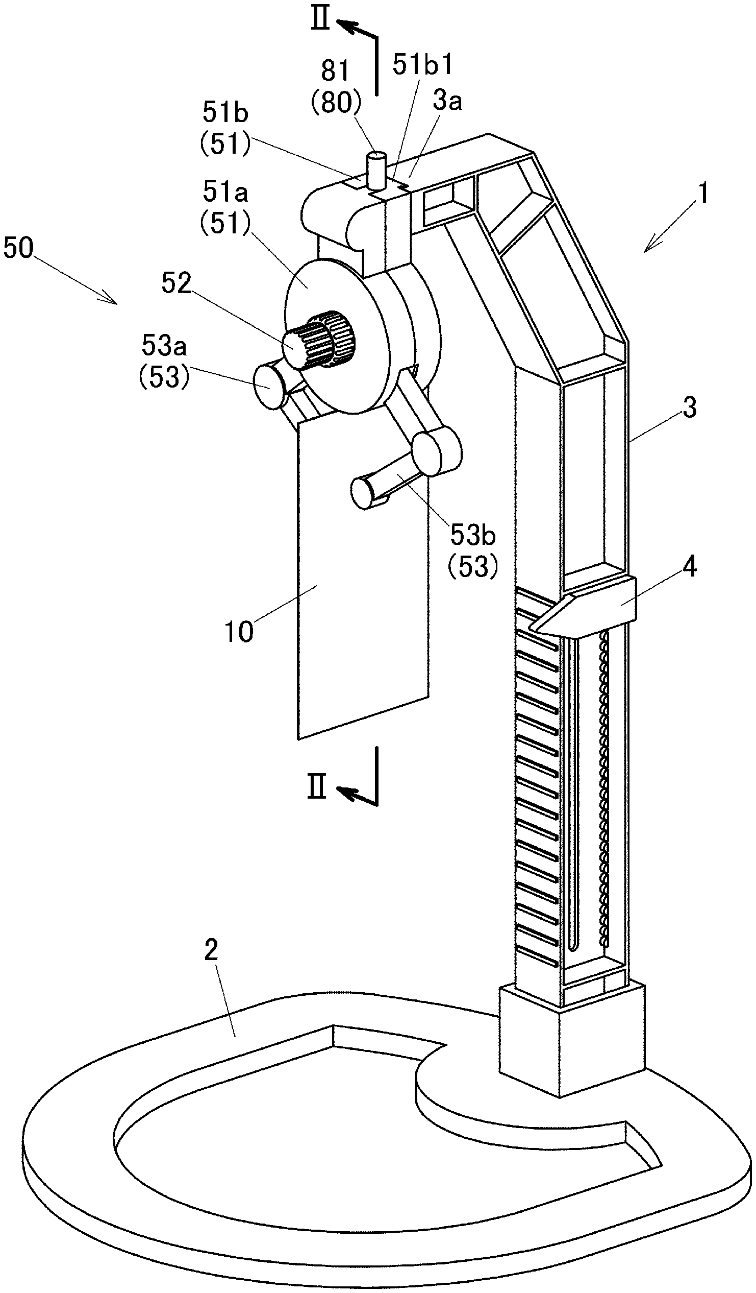
[0010] FIG. 1 is a perspective view of a falling object catching toy according to an embodiment of the present invention.
[0011] FIG. 2 is a cross-sectional view of FIG. 1, taken at line II-II, of a holding device of the falling object catching toy according to the embodiment of the present invention.
[0012] FIG. 3A is an enlarged front view around the holding device of the falling object catching toy according to the embodiment of the present invention with the front case omitted, showing a holding state of holding members.
[0013] FIG. 3B is an enlarged front view around the holding device of the falling object catching toy according to the embodiment of the present invention with the front case is omitted, showing a state where the holding state is released.
[0014] FIG. 4 is a perspective view of a rotation knob of the falling object catching toy according to the embodiment of the present invention.
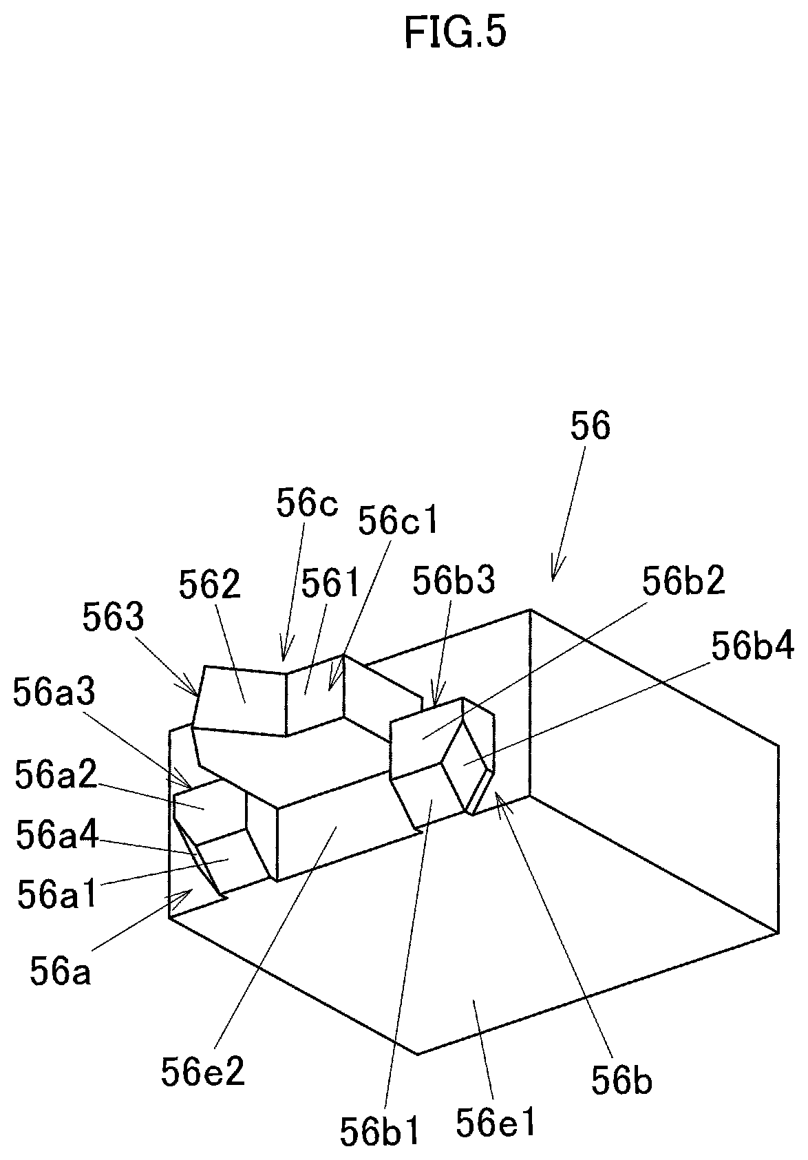
[0015] FIG. 5 is a perspective view of a piece body according to the embodiment of the present invention.
DETAILED DESCRIPTION OF THE PREFERRED EMBODIMENT
[0016] An embodiment of the present invention will now be described with reference to the drawings. In the following descriptions, with regard to a falling object catching toy 1, the side on which a holding device 50 is provided is the front face side or front side, and the opposite side thereof is the rear face side or rear side. A left-to-right direction when viewing the falling object catching toy 1 from its front face side will be described as the left-to-right direction.
[0017] When playing with the falling object catching toy 1, firstly, the holding device holds a paper note or the like (falling object 10). Then, below the holding device 50, a user positions his/her fingers with the back of his/her hand facing up such that the falling object 10 falls between the forefinger and the middle finger. Upon pressing an operation button 81 of a spiral-spring driving operation part 80 of the holding device 50, whose spiral spring has been wound in advance by rotating a rotation knob 52, the spiral spring operates to release the falling object 10 at a predetermined timing, and the falling object 10 falls down. The user moves his/her fingers so as to sandwich and catch the falling object 10 with the forefinger and the middle finger. In this manner, a game in which players compete whether or not they can catch the falling object 10 falling down can be played.
[0018] The falling object catching toy 1 includes a flat ring-shaped base 2 and a supporting column 3 that erects upwardly from the top surface of the rear part of the base 2. The substantially rod-like supporting column 3 is curved at the upper part so as to bend down forward, and its edge extends a little so as to form a holding device support part 3a. The holding device support part 3a formed in a recessed groove shape is engaged with a sliding-engaging part 51b1 formed in the upper part of the back surface of a rear case 51b of the holding device 50, and thus, the holding device 50 is detachably supported by the supporting column 3 (holding device support part 3a).
[0019] A height indicating part 4 that indicates the height position of the fingers catching the falling object 10 falling down is formed in a part that extends straightly from the base 2 of the supporting column 3. The height indicating part 4 is formed in a flat plate form having an arrow shape, and is provided in a manner that is movable along the straight part of the supporting column 3. Further, its position can be maintained at a desired height.
[0020] The holding device 50 includes a case body 51 in which a spiral-spring driving part 55 and a holding-maintenance release structure 60 (see FIG. 2) described later are mounted inside. The case body 51 is formed in a divided manner with a front case 51a on the front side and the rear case 51b on the rear side. With regard to the case body 51, the upper part engaging with the supporting column 3 is formed in a substantially rectangular solid shape that is a substantially straight shape, and the lower side is formed to have a circular outer shape. The upper part of the front face side of the case body 51 having a substantially straight shape (i.e., the upper part of the front case 51a) projects in a semi-cylindrical shape. With regards to the holding device 50, the rotation knob 52 projects substantially from the center of the lower circular part of the case body 51. A pair of holding members 53 are formed so as to project downwardly from side surfaces in the lower part of the lower circular part of the case body 51. The holding members 53 include a left holding member 53a and a right holding member 53b such that they are able to hold the falling object 10.
[0021] As shown in FIG. 3A, the holding members 53 are formed in a substantially V-shape, and are rotatably and pivotally supported within the case body 51. A tip side member 53a2 and a rear-end side member 53a3 that sandwich a bent part 53a1 of the left holding member 53a, which is one of the holding members 53, are pivotally coupled with the bent part 53a1. The rotation of the tip side member 53a2 is regulated by the width of a notch on the side surface of the bent part 53a1 that is formed in a cylindrical shape. With regard to the bent part 53a1, a biasing member 53a4 that is a torsion coil spring is provided inside. With this biasing member 53a4, the tip side member 53a2 is biased to a closing direction (the direction approaching the other holding member 53b). The bent part 53b1 of the right holding member 53b, which is the other part of the holding members 53, is a bent part that does not rotate.
[0022] The left holding member 53a and the right holding member 53b are pivotally supported with shafts 51c1, 51c2 that are formed in the case body 51, respectively. An opening direction of the left holding member 53a and the right holding member 53b is regulated by abutment on an opening end 51d in the lower part of the case body 51. The left holding member 53a and the right holding member 53b are each formed to have, on their rear ends, engaging plate parts 53a5, 53b5 that extend in a plate shape. As shown in FIG. 3A, the engaging plate parts 53a5, 53b5 extend such that they become horizontal in the left-to-right direction in the closing state (holding state) of the holding members 53. Further, biasing members 54a, 54b that are torsion coil springs are provided around the shafts 51c1, 51c2. One of the arms of the biasing members 54a, 54b, which are torsion coil springs, abuts on the case body 51, and the other arm abuts on the holding members 53a, 53b. Due to these biasing members 54a, 54b, the holding members 53 are biased to the opening direction. In this manner, the holding members 53 are formed such that they are capable of holding the falling object 10 with their tip parts.
[0023] As shown in FIG. 2, the rotation knob 52 is rotatably provided in substantially the center of the circular lower part of the case body 51. The rotation knob 52 is formed in a substantially cylindrical shape, and its front side is formed to have a small diameter, while its rear side is formed to have a large diameter. A protruding part 52a that extends in a radially outward direction is formed on the outer circumference of the large diameter side of the rotation knob 52 (also see FIG. 4). The protruding part 52a is formed in a triangular prism shape with its apex part faced to the back side, and is positioned within the case body 51.
[0024] In the rear case 51b, the spiral-spring driving part 55 is provided so as to oppose the rotation knob 52. With respect to the spiral-spring driving part 55, a driving shaft 55a projects from the case of the spiral-spring driving part 55 within which a spiral spring, gear, or the like is provided. The rotation knob 52 is connected and fixed to the driving shaft 55a of the spiral-spring driving part 55. Accordingly, the spiral spring can be wound by rotating the rotation knob 52 to the right when viewed from the front face side, and once the spiral-spring driving part 55 is activated, the rotation knob 52 rotates to the left.
[0025] A piece body 56 shown in FIG. 2 and FIG. 5 is provided below the spiral-spring driving part 55. The piece body 56 is formed in a substantially bottomed square tube shape with its bottom part facing the front face side, and is biased to the front with a biasing member 56d that is a coil spring. Bias of the piece body 56 to the front side is regulated by abutting a front surface 56e2 of the piece body 56 shown in FIG. 5 on a rib 51a1 that is provided inside the front case 51a shown in FIG. 2.
[0026] As shown in FIG. 5, the front face side of the piece body 56 is provided with a left regulating part 56a and a right regulating part 56b that project in substantially symmetrical shapes in the right and left, respectively. Inclined surfaces 56a1, 56b1, which are under surfaces of the regulating parts 56a, 56b, are surfaces that incline continuously and upwardly from an under surface 56e1 of the piece body 56. End surfaces 56a2, 56b2 of the regulating parts 56a, 56b are flat surfaces that are in parallel with a front surface 56e2 of the piece body 56. Top surfaces 56a3, 56b3 of the regulating parts 56a, 56b are flat surfaces that are in parallel with the under surface 56e1. Outer surfaces that are adjacent to the inclined surfaces 56a1, 56b1 are inclined surfaces 56a4, 56b4 that incline toward the end surfaces 56a2, 56b2.
[0027] A releasing protrusion 56c is formed between the regulating parts 56a, 56b. The front surface of the releasing protrusion 56c is a cam surface 56c1. The cam surface 56c1 is formed with a flat surface 561 that is in parallel with the front surface 56e2, a right inclined surface 562 that ascends from the flat surface 561, and a left inclined surface 563 that descends from the right inclined surface 562, in order from the right.
[0028] As shown in FIG. 2 and FIG. 3A, the spiral-spring driving operation part 80 is formed above the spiral-spring driving part 55. With an operation of the spiral-spring driving operation part 80, the spiral-spring driving part 55 is set to a state capable of winding up, or the wound-up spiral spring is released and the driving shaft 55a is rotated. The spiral-spring driving operation part 80 is formed in a cylindrical shape that is vertically long, and is provided with the operation button 81 having an upper end that projects from the upper part of the rear case 51b. For the side surface of the operation button 81, two positions, namely an upper position and a lower position can be set by engagement with an engaging protrusion member 82 that is provided inside the upper part of the case body 51.
[0029] A spiral-spring actuating member 84 of the spiral-spring driving operation part 80 is connected to the upper part of the spiral-spring driving part 55. The spiral-spring actuating member 84 is formed in a substantially cylindrical shape that is vertically long. Once the spiral-spring actuating member 84 is pressed into the spiral-spring driving part 55, the spiral spring is set to a state where it can be wound up with the driving shaft 55a of the spiral-spring driving part 55, and once the spiral-spring actuating member 84 is lifted upward, the wound-up spiral spring is released.
[0030] A link member 83 is provided between the lower part of the operation button 81 and the upper part of the spiral-spring actuating member 84. The center of the link member 83 is pivotally supported and is also swingably supported. Long holes are formed at both ends of the link member 83. A shaft is formed in each of the lower part of the operation button 81 and the upper part of the spiral-spring actuating member 84, respectively, for coupling with each of the long holes at both ends of the link member 83. In this manner, when the operation button 81 of the spiral-spring driving operation part 80 is pressed to be set to the lower position, the spiral-spring actuating member 84 rises via the link member 83, and the spiral spring of the spiral-spring driving part 55 is released, thereby rotating the driving shaft 55a to the left. When the operation button 81 is lifted to set the operation button 81 to the upper position, the spiral-spring actuating member 84 descends via the link member 83. Thus, since the spiral spring of the spiral-spring driving part 55 is prevented from returning, the spiral spring of the spiral-spring driving part 55 can be wound up by rotating the driving shaft 55a to the right.
[0031] As shown in FIG. 3A, when the holding members 53 are closed, the top surfaces 56a3, 56b3 of the regulating parts 56a, 56b of the piece body 56 abut on the lower edge surfaces of the engaging plate parts 53a5, 53b5. By their abutment, the bias of the holding members 53 in the opening direction is regulated. When the protruding part 52a of the rotation knob 52 abuts on the releasing protrusion 56c and the piece body 56 temporarily moves to the back against the biasing force, as shown in FIG. 3B, abutment of the top surfaces 56a3, 56b3 of the regulating parts 56a, 56b of the piece body 56 on the lower edge surfaces of the engaging plate parts 53a5, 53b5 is released, thereby releasing the regulation of bias of the holding members 53 in the opening direction to release the holding state. At this point, the engaging plate parts 53a5, 53b5 of the holding members 53 that are biased in the opening direction abut on the end surfaces 56a2, 56b2 of the regulating parts 56a, 56b of the piece body 56 that is biased forward.
[0032] Here, when the holding members 53 are in the holding state, by rotating the tip side member 53a2 of the left holding member 53a against the biasing force by the biasing member 53a4 in the bent part 53a1, the tip parts of the holding members 53 slightly open, and the falling object 10 can be inserted and sandwiched between the tip parts of the holding members 53. The biasing member 53a4 also functions as a cushion (play adjustment) in a state in which the tip parts of the holding members 53 abut on each other.
[0033] The holding-maintenance release structure 60, which is capable of maintaining the holding state of the falling object 10 with the holding members 53 or releasing such holding state, includes the protruding part 52a of the rotation knob 52, the piece body 56 having the regulating parts 56a, 56b, the releasing protrusion 56c, and the biasing member 56d, the engaging plate parts 53a5, 53b5 of the holding members 53, and the biasing members 54a, 54b of the holding members 53. As shown in FIG. 2, with regard to the fore-and-aft position of the holding-maintenance release structure 60, the protruding part 52a and the releasing protrusion 56c are in interfering positions while the regulating parts 56a, 56b and the engaging plate parts 53b5, 53b5 of the holding members 53a, 53b are positioned further backward than the protruding part 52a. Accordingly, the protruding part 52a does not interfere with the regulating parts 56a, 56b nor the engaging plate parts 53a5, 53b5.
[0034] The playing procedures and the operations of each part will now be described. Firstly, the operation button 81 is pulled upward to rotate the rotation knob 52 to the right. Then, the spiral spring of the spiral-spring driving part 55 is wound up. Once the rotation knob 52 is rotated to the right, the protruding part 52a also rotates to the right.
[0035] The protruding part 52a of the rotation knob 52 passes the front of the piece body 56 from right to left while rotating. At this point, the protruding part 52a relatively moves along the right inclined surface 562 of the releasing protrusion 56c of the piece body 56, while moving the piece body 56 backward against biasing force of the biasing member 56d. At this point, the holding state of the holding members 53 is released. Accordingly, after completing winding up of the spiral spring, the falling object 10 is held with the holding members 53.
[0036] Alternatively, the cam surface 56c1 can be set such that the front/rear distance of the surface where the top surfaces 56a3, 56b3 of the regulating parts 56a, 56b abut on the engaging plate parts 53a5, 53b5 becomes smaller than the front/rear moving distance of the piece body 56 in accordance with the relative movement of the protruding part 52a along the right inclined surface 562. In this case, since the holding state of the holding members 53 will not be released even if the spiral spring is wound up by rotating the rotation knob 52 to the right, the spiral spring can be wound up while the falling object 10 is held with the holding members 53 (the playing procedures can be set as desired).
[0037] Once the spiral spring is wound up using the rotation knob 52 to hold the falling object 10 with the holding members 53, the operation button 81 is pressed down. Then, the driving shaft 55a of the spiral-spring driving part 55 rotates to the left, and the rotation knob 52 and the protruding part 52a rotate to the left. As the protruding part 52a comes rotating to the front of the piece body 56, the protruding part 52a moves from the left to the right of FIG. 5. That is, the cam surface 56c1 is set such that the front/rear distance of the surface where the top surfaces 56a3, 56b3 of the regulating parts 56a, 56b abut on the engaging plate parts 53a5, 53b5 becomes longer than the front/rear moving distance of the piece body 56 in accordance with the relative movement of the protruding part 52a along the left inclined surface 563. Accordingly, once the rotation knob 52 rotates by driving force of the spiral-spring driving part 55 and the protruding part 52a abuts on the releasing protrusion 56c, the holding state of the holding members 53 is released. Then, the falling object 10 falls down, and the user catches this.
[0038] When a rotation is made until the engaging plate parts 53a5, 53b5 abut on the opening end 51d of the case body 51, the upper edges of the engaging plate parts 53a5, 53b5 are positioned on the inclined surfaces 56a1, 56b1 or the inclined surfaces 56a4, 56b4 of the regulating parts 56a, 56b. In this case, by manually rotating the holding members 53 in the closing direction, the engaging plate parts 53a5, 53b5 move along the inclined surfaces 56a1, 56b1 or the inclined surfaces 56a4, 56b4, thereby achieving the holding state.
[0039] The abutment of the protruding part 52a of the rotation knob 52 provided inside the case body 51 on the releasing protrusion 56c (left inclined surface 563) of the piece body 56 is invisible from the user. Accordingly, the user is unable to recognize the timing at which the holding members 53 release the falling object 10. In this manner, a game in which users compete whether or not they can catch the falling object 10 can be played.
[0040] Further, since the difficulty level is elevated as the height of the height indicating part 4 becomes higher (that is, closer to the holding members 53), games having elevated difficulty levels can also be enjoyed.
[0041] Although the embodiment of the present invention has been described above, the present invention is not limited to the present embodiment, and various modifications can be made. For example, the holding device 50 can be detached from the supporting column 3, followed by attachment to a hair band or the like, and the game can be played by causing a falling object to drop right in front of oneself. Moreover, the rotation knob 52 can be formed such that a large-diameter part including the protruding part 52a and a small-diameter part are separate bodies. In this case, the rotation position of the protruding part 52a can be set to be random by adding appropriate changes such as using a ratchet structure for the connection of the large-diameter part and the small-diameter part.
* * * * *
D00000
D00001
D00002
D00003
D00004
D00005
XML
uspto.report is an independent third-party trademark research tool that is not affiliated, endorsed, or sponsored by the United States Patent and Trademark Office (USPTO) or any other governmental organization. The information provided by uspto.report is based on publicly available data at the time of writing and is intended for informational purposes only.
While we strive to provide accurate and up-to-date information, we do not guarantee the accuracy, completeness, reliability, or suitability of the information displayed on this site. The use of this site is at your own risk. Any reliance you place on such information is therefore strictly at your own risk.
All official trademark data, including owner information, should be verified by visiting the official USPTO website at www.uspto.gov. This site is not intended to replace professional legal advice and should not be used as a substitute for consulting with a legal professional who is knowledgeable about trademark law.